

CNE Series
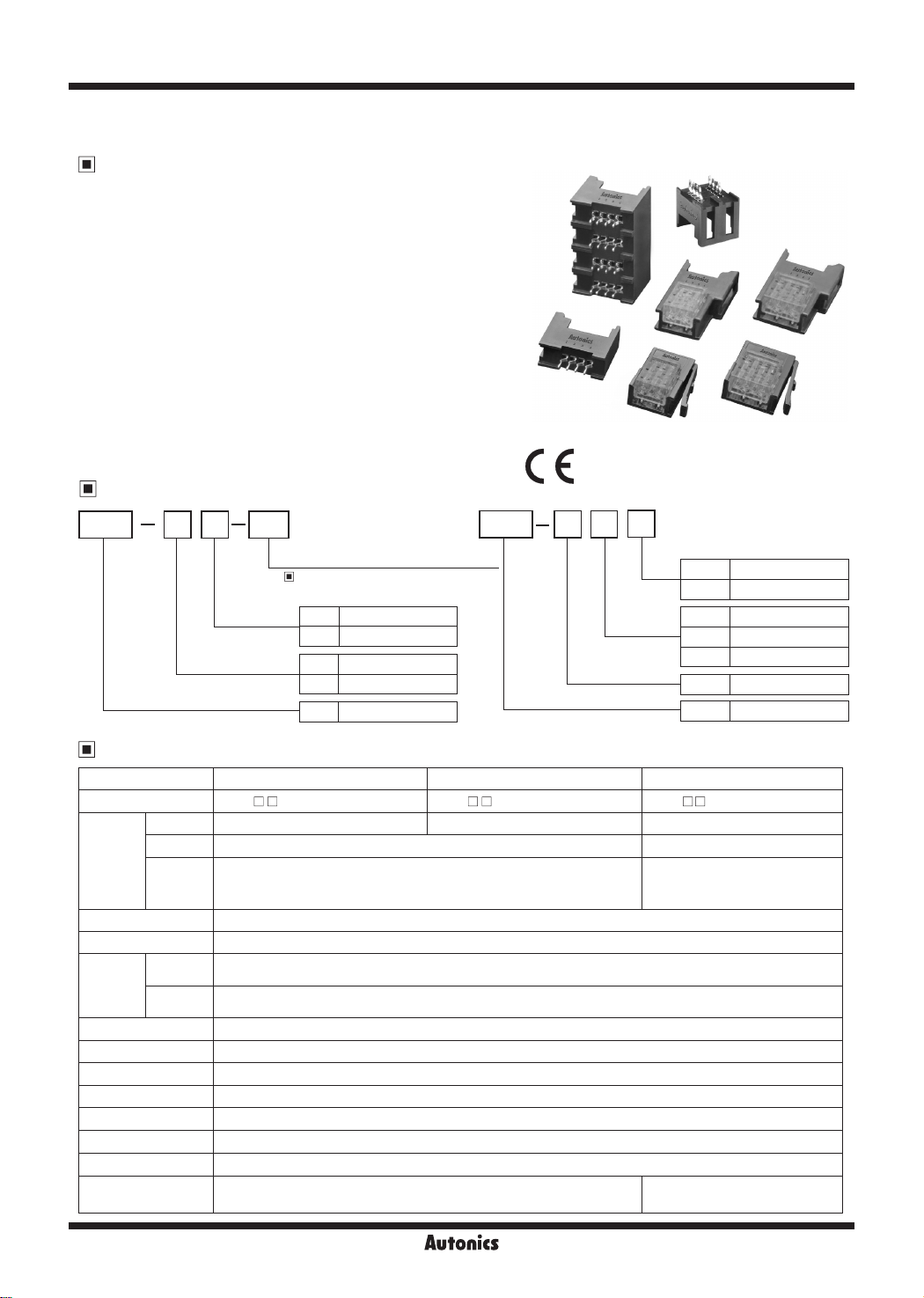
Sensor Connector
Features
Wire mount plug/socket
■
● Compact and highly reliable of pressure welding connector
● Enables to connect wires as wire mount plug/socket
● Different 9 colors of cover by wire diameter
● Visible wiring status with translucent cover
Board mount socket
■
● Enables to insert 4, 2, or 1 wire mount plugs
● Contact placed in mold against electric shock and short-circuit
● Mountable on board closely
Commons
■
● Significantly reduces connection time and effort
● Wide products range for various wires
● Compact and high density installation with 2mm of contact pitch
● Max. 3A of current capacity by a pin
Ordering Information
CNE
Item
Specications
Type Wire mount plug Wire mount socket Board mount socket
Model CNE-P
Application
Rated voltage Max. 250VACᜠ/DC
Rated current Max. 3 0A
Environment
Terminal retention Min. 1.4kgf
Pressure strength
Extraction Min. 0.49N (50gf)/pin
Insertion Max. 1 96N (200gf)/pin
Dielectric strength 1,000VAC for 1min (between terminals)
Insulated resistance Over 1,000MΩ (between terminals)
Contact resistance Max. 0 05Ω (short-current: 1mA, max. open voltage: 20mV)
Material
G-2
PB03
Connector type
Connector Board mount socket/Wire mount socket Wire mount plug Wire mount plug
Cable AWG30-20 (Ø0.6mm to Ø2.0mm)
PCB
Ambient
temp.
Ambient
humi.
WT
-~
Cover color (wire specications)
'-----;;~;---------
※
Cover color and wire specications’
‘
(Refer to page G-3)
Pins
-
-20 to 85℃ (applying 1A), -20 to 75℃ (applying 2A), -20 to 60℃ (applying 3A)
40 to 80%RH
AWG30: Min. 0.5kgf ● AWG24: Min. 0.8kgf ● AWG20: Min. 1.0kgf
●
Body: PC/ABS (UL94V-0), Terminal: C5210 (gold 0.2μm),
Case: PC (UL94-V0)
03 3-pin
04 4-pin
P Wire mount plug
S Wire mount socket
CNE Sensor connector
- CNE-S - CNE-B
□□
ᜡ
Auton1cs
CNE
Connector type
Item
□□
.
03
2
Pins
1
Lines
03 3-pin
04 4-pin
No-mark
2 2-line
4 4-line
B Board mount socket
CNE Sensor connector
□□
-
Fender plated-through hole,
Hole dia.: 1.0mm,
PCB thickness: 1.0 to 2.2mm
Body: PC/ABS (UL94-V0),
Terminal: C5210 (gold 0.2μm)
I
1-line
Cover Color and Wire Specications
Cover color 3-pin 4-pin
Transparent (WT) CNE-
Yellow-Green (YG) CNE-
Violet (VT) CNE-
Red (RE) CNE-
Yellow (YW) CNE-
Orange (OG) CNE-
Green (GN) CNE-
Blue (BL) CNE-
Gray (GY) CNE-
※
P (wire mount plug), S (wire mount socket)
:
□
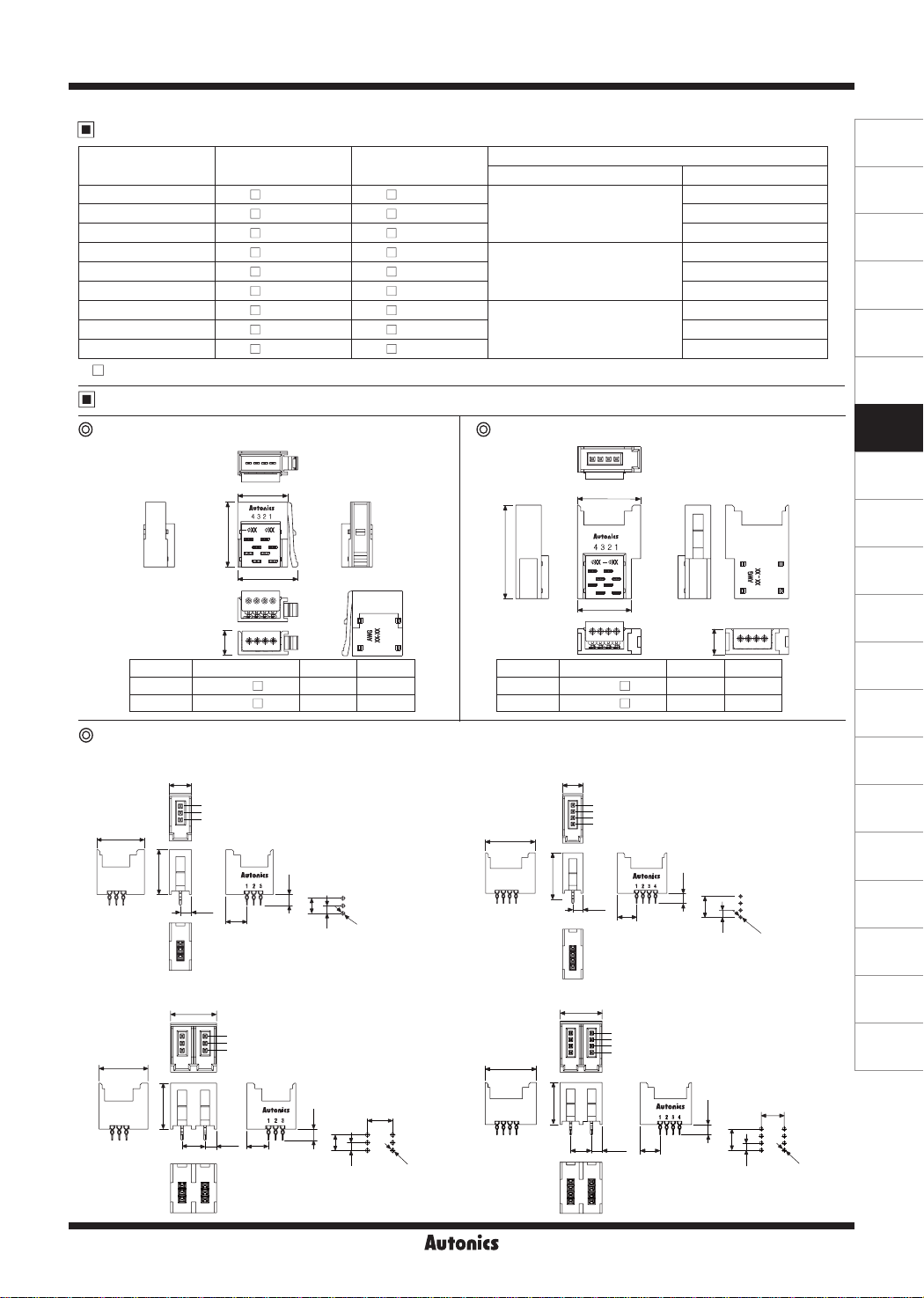
Dimensions
03-WT CNE- 04-WT
□ □
03-YG CNE- 04-YG Ø0.8 to 1 0
□ □
03-VT CNE- 04-VT Ø1.0 to 1 2
□ □
03-RE CNE- 04-RE
□ □
03-YW CNE- 04-YW Ø1.0 to 1 2
□ □
03-OG CNE- 04-OG Ø1.2 to 1.6
□ □
03-GN CNE- 04-GN
□ □
03-BL CNE- 04-BL Ø1.2 to 1.6
□ □
03-GY CNE- 04-GY Ø1.6 to 2 0
□ □
Wire mount plug
(unit: mm)
A
16
B
Sensor Connector
Applied wire specications
Nominal cross section area (mm²)
0.05 to 0.08
(AWG30 to 28)
0.13 to 0.21
(AWG26 to 24)
0.32 to 0.5
(AWG22 to 20)
Wire mount socket
A
23.5
Cover diameter (mm)
Ø0.6 to 0 8
Ø0.8 to 1 0
Ø1.0 to 1 2
(unit: mm)
(A)
Photoelectric
Sensors
(B)
Fiber
Optic
Sensors
(C)
Door/Area
Sensors
(D)
Proximity
Sensors
(E)
Pressure
Sensors
(F)
Rotary
Encoders
(G)
Connectors/
Connector Cables/
Sensor Distribution
Boxes/ Sockets
(H)
Temperature
Controllers
(I)
SSRs / Power
Controllers
(J)
Counters
After
crimping
5.9
Pins Model A B
3 CNE-P034 CNE-P04-
Board mount socket
● CNE-B03 (1-line×3-pin)
6.5
3
2
13.8
● CNE-B203 (2-line×3-pin)
13.8
1
13
3.2
6
13
3
2
1
13
3.2
6.5
6
10.5 14.5
12.5 16.5
3.2
4
2
PCB hole
pattern
3.2
4
Ø1
6.5
2
PCB hole
pattern
B
~
crimping
6.5
UBt~
After
Pins Model A B
3 CNE-S034 CNE-S04-
I I
13 8 11.5
15 8 13.5
~
I I
(unit: mm)
● CNE-B04 (1-line×4-pin)
6 5
4
3
2
15 8
1
13
3.2
6
3.2
6
2
PCB hole
pattern
Ø1
● CNE-B204 (2-line×4-pin)
13
4
3
2
6.5
3.2
1
6
6.5
2
PCB hole
pattern
Ø1
3.2
6
15.8
13
Ø1
(K)
Timers
(L)
Panel
Meters
(M)
Tacho /
Speed / Pulse
Meters
(N)
Display
Units
(O)
Sensor
Controllers
(P)
Switching
Mode Power
Supplies
(Q)
Stepper Motors
& Drivers
& Controllers
(R)
Graphic/
Logic
Panels
(S)
Field
Network
Devices
(T)
Software
Autonics
G-3

CNE Series
Dimensions
Board mount socket
● CNE-B403 (4-line×3-pin) ● CNE-B404 (4-line×4-pin)
26
3
2
3.2
1
19.5
6.5
3.2
6
4
2
PCB hole
pattern
Ø1
15.8
13.8
13
6.5
Wiring Sensor Connector
1) Select connector
Check the wire specifications (conductor section, cover diameter).
●
Select the proper color of sensor connector (model) by referring to the below table.
●
Cover color Wire mount plug Wire mount socket
Transparent (WT) CNE-P
Yellow-Green (YG) CNE-P
Violet (VT) CNE-P
Red (RE) CNE-P
Yellow (YW) CNE-P
Orange (OG) CNE-P
Green (GN) CNE-P
Blue (BL) CNE-P
Gray (GY) CNE-P
※
: Number of pins (03: 3-pin, 04: 4-pin)
□
※
The proper sensor connector may be different by conductor of wire.
※
Cover diameter of applied wire at connector (at translucent part)
-WT CNE-S -WT
□ □
-YG CNE-S -YG Ø0.8 to 1.0
□ □
-VT CNE-S -VT Ø1.0 to 1.2
□ □
-RE CNE-S -RE
□ □
-YW CNE-S -YW Ø1.0 to 1.2
□ □
-OG CNE-S -OG Ø1.2 to 1.6
□ □
-GN CNE-S -GN
□ □
-BL CNE-S -BL Ø1.2 to 1.6
□ □
-GY CNE-S -GY Ø1.6 to 2.0
□ □
and AWG number of body backside are marked.
Applied wire specications
Nominal cross section area (mm²) Cover diameter (mm)
0.05 to 0.08
(AWG30 to 28)
0.13 to 0.21
(AWG26 to 24)
0.32 to 0.5
(AWG22 to 20)
26
4
3
2
1
13
6.5
3.2
6
Ø0.6 to 0.8
Ø0.8 to 1.0
Ø1.0 to 1.2
(unit: mm)
19.5
6.5
3.2
6
2
PCB hole
pattern
Ø1
2) Insert the wires
Check the pin numbers and insert the wires into the
●
according holes.
Check that the wires are fully inserted to the end of the
●
cover.
3) Crimping
Insert the cover into the body with a jig (press fitting tool,
●
etc).
Apply pressure with the jig from the side, as shown in
※
the figure below
G-4
4) Check the cover
Check to make sure that the cover is level with the body
●
and that there is no space between the cover and the
body.
Not enough cover insertion. Not enough cover insertion.
Autonics
Wrong (1) Wrong (2)
※
Press the part of arrows again.
 Loading...