

Autonics CN-6000 Series Catalog Page
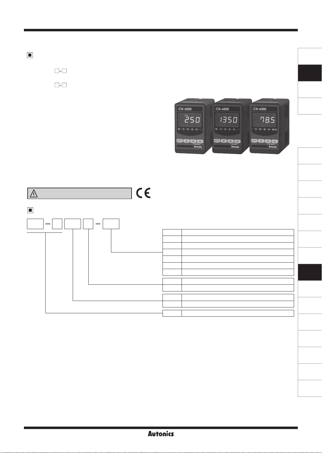
Isolated Converter
Features
● Multi-input
- CN-610 : Thermocouple 12 types, RTD 5 types,
- CN-640 : 0 to 50.00kHz
● Improves visibility with negative LCD
: 12-segment, 3 colors (selectable red, green, yellow)
● Displays input type and unit on display part
● Various outputs
: 4, 2, 1 alarm output, 0-20mA transmission output
(adjustable insulation, output range),
0-10VDC voltage output
(adjustable insulation, output range)
● Various functions
: High/Low peak monitoring, sensor disconnection
alarm output (burn-out), input correction, user input
range, display scale, transmission output scale,
analog output range setting
● Built-in power supply for sensor (24VDC)
Ordering Information
□-□
□-□
analog (mV, V, mA) 6 types
□-□
Please read “Safety Considerations”
in the instruction manual before using.
6CN 10 0 C1
Power supply
Input
Item
Output
CN-6000 Series
,·:::..c-.~--,-·~-
..
-.
CN-6000
250
.
cma&l!,P
Auto11ic.s
C1 Transmission output (0-20mA): 1
C2 Transmission output (0-20mA): 2
V1 Transmission output (0-10VDC): 1
V2 Transmission output (0-10VDC): 2
R1 Alarm output: 1
R2 Alarm output: 2
R4 Alarm output: 4
0 100-240VAC 50/60Hz
1 24VDC
10 Universal input
40 Pulse input (※option)
CN-6 Isolated Converter
CN-6000 CN-6000
1350
.
cma&l!,P
Autonics
'l
B.S
.
"
"
••&l!,P
Autonics
,.
SENSORS
CONTROLLERS
MOTION DEVICES
SOFTWARE
'
(J)
Temperature
Controllers
(K)
SSRs
(L)
Power
Controllers
(M)
Counters
(N)
Timers
(O)
Digital
Panel Meters
(P)
Indicators
(Q)
Converters
(R)
Digital
Display Units
(S)
Sensor
Controllers
(T)
Switching
Mode Power
Supplies
Autonics
Q-3
(U)
Recorders
(V)
HMIs
(W)
Panel PC
(X)
Field Network
Devices
CN-6000 Series
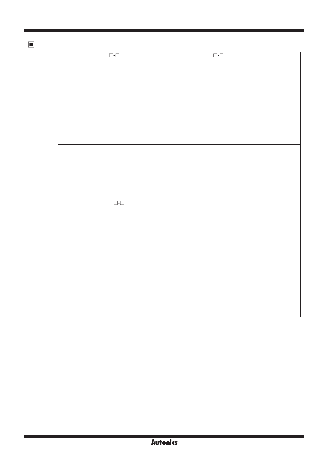
Specifications
~
Model CN-610
AC voltage 100-240VACᜠ 50/60Hz
Power supply
Allowable voltage range 90 to 110% of rated voltage
Power
consumption
Display method
Character size Display part: 6.4×11.0mm (12-segment), input type/unit display part: 1.4×2.75mm (unit)
Input type
Output
Display accuracy
Setting method Set by front keys
Sampling cycle
Display cycle
Dielectric voltage 2000VAC 50/60Hz for 1 min (between input terminal and power terminal)
Vibration 0.75mm amplitude at frequency of 5 to 55Hz (for 1 min) in each X, Y, Z direction for 2 hours
Insulation resistance Over 100MΩ (at 500VDC megger)
Noise immunity ±2kV the square wave noise (pulse width 1㎲) by noise simulator
Memory retention Approx. 10 years (non-volatile semiconductor memory type)
Environment
Approval
Weight
※
1: The weight includes packaging. The weight in parenthesis is for unit only.
※
Environment resistance is rated at no freezing or condensation.
l
DC voltage 24VDCᜡ
J
AC voltage Max. 8VA
l
DC voltage Max. 3W
J
RTD JPt100Ω, DPt100Ω, DPt50Ω, Cu50Ω, Cu100Ω
Thermocouple K, J, E, T, R, B, S, N, C, L, U, PLII
Analog
Pulse input
Transmission
output
Alarm output
Ambient
temperature
Ambient
humidity
※
1
□-□
12-segment (selectable red, green, yellow) graphic bar and input type/unit display part (red) with
LCD method
• Voltage: -50.0-50.0mV, -199.9-200.0mV,
-1.000-1.000V, -1.00-10.00V
• Current: 0.00-20.00mA, 4.00-20.00mA
-
0-20mA (adjustable output range), load resistance max. 600Ω (accuracy: ±0.3 F.S.,
resolutions: 8000)
0-10VDCᜡ (adjustable output range), load resistance min. 10kΩ (accuracy: ±0.3 F.S.,
resolutions: 8000)
1-point: relay contact capacity 250VAC 5A 1a
2-point: relay contact capacity 250VAC 3A 1c
4-point: relay contact capacity 250VAC 5A 1a
±0.2%F.S. ±1-digit (25±5℃), ±0.3%F.S. ±1-digit (-10 to 20℃, 30 to 50℃)
※
CN-610
Analog input: 100ms, temperature sensor input:
250ms
-
-10 to 50℃, storage: -20 to 60℃
35 to 85%RH, storage: 35 to 85%RH
ᜢ
Approx. 301g (approx. 160g) Approx. 340g (approx. 200g)
: for TC, the input below -100℃ is ±0.4%F.S. ±1-digit (TC-T, TC-U is min. ±2.0℃)
□-□
CN-640
J
□-□
-
-
-
0 to 50.00kHz (input impedance: 10kΩ)
-
Same with pulse input cycle
When pulse input cycle is over 10 sec, it is
updated by every 10 sec
-
j
J
Q-4
Isolated Converter
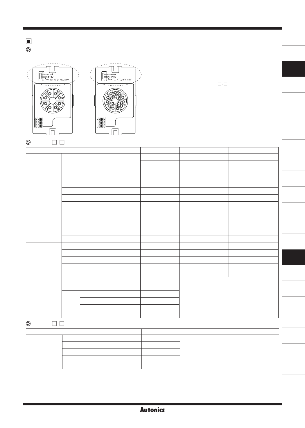
Input Type and Range
Input type selection switch
●
8-pin
CN-610 - (universal input)
□□
Input type Parameter Input range (℃) Input range (℉)
K(CA)
J(IC)
E(CR)
T(CC)
B(PR)
Thermocouple
R(PR)
S(PR)
N(NN)
C(W5)
L(IC)
U(CC)
Platinel II
Cu50Ω
Cu100Ω
RTD
JPt100Ω
DPt50Ω
DPt100Ω
Current
Analog
Voltage
CN-640 - (pulse input)
□□
Input type Measuring cycle Parameter Range
0 to 9.999Hz Max. 10 sec
0 to 99.99Hz Max. 10 sec
Pulse
0 to 999.9Hz Max. 10 sec
0 to 9.999kHz Max. 1 sec
0 to 50.00kHz Max. 0.1 sec
※
Pulse input: Non-contact 0 to 50kHz, Contact 0 to 45Hz (displays 0 for below 0.1Hz)
※
Input Low Level: 0-1VDC / Input High Level: 5-24VDC
※
Duty Ra io: 30 to 70%
※
The principle of displaying frequency is converting the time dierence between input pulses to the frequency. 1 sec is required to measure
1Hz, and 10 sec is required to measure 0.1Hz. Therefore, it is normal that the lower pulse, he slower response speed. In case of 0Hz, if
there are no pulses for over 2 sec, it is programmed to display 0Hz to prevent slow response speed.
●
11-pin
0.00 - 20.00mA
4.00 - 20.00mA
-50.0 - 50.0mV
-199.9 - 200.0mV
-1.000 - 1.000V
-1.00 - 10.00V
● mA: Select it for 0(4)-20mA input
● 10V: Select it for -1V-10V input
● TC, RTD, mV, ±1V: Select it for TC, RTD or ±1mV, V input
※
The pulse input model (CN- 640
type selection switch.
This product is multi-input. Select the desired input type by the
●
input type selection switch and select the input type at [
The selection of the input type selection switch and that of [
●
) does not have this input
□-□
IN P
should be same to display correct value.
Factory default is 4-20mA.
TcK1
TcK2
TC-J
TC-E
TC-T
TC- B
TC-R
TC-S
TC-N
TC-C
TC-L
TC-U
TC-P
Cu50
Cu10
JPt1
DPt5
DPt1
-200 to 1350 -328 to 2462
-199.9 to 999.9 -328 to 1832
-199.9 to 800.0 -328 to 1472
-199.9 to 800.0 -328 to 1472
-199.9 to 400.0 -199.9 to 752.0
400 to 1800 752 to 3272
0 to 1750 32 to 3182
0 to 1750 32 to 3182
-200 to 1300 -328 to 2372
0 to 2300 32 to 4172
-199.9 to 900.0 -328 to 1652
-199.9 to 400.0 -199.9 to 752.0
0 to 1390 32 to 2534
-199.9 to 200.0 -199.9 to 392.0
-199.9 to 200.0 -199.9 to 392.0
-199.9 to 600.0 -328 to 1112
-199.9 to 600.0 -328 to 1112
-199.9 to 850.0 -328 to 1530
aMA1
aMA2
aMV1
aMV2
-1999 to 9999
(display range depends
on the decimal point position)
A-V1
A-V2
10H
100H
1KH
10KH
-1999 to 9999
(display range is variable
according to decimal point position.)
50KH
]
IN P
SENSORS
CONTROLLERS
MOTION DEVICES
SOFTWARE
]
(J)
Temperature
Controllers
(K)
SSRs
(L)
Power
Controllers
(M)
Counters
(N)
Timers
(O)
Digital
Panel Meters
(P)
Indicators
(Q)
Converters
(R)
Digital
Display Units
(S)
Sensor
Controllers
(T)
Switching
Mode Power
Supplies
(U)
Recorders
(V)
HMIs
(W)
Panel PC
(X)
Field Network
Devices
Autonics
Q-5
CN-6000 Series
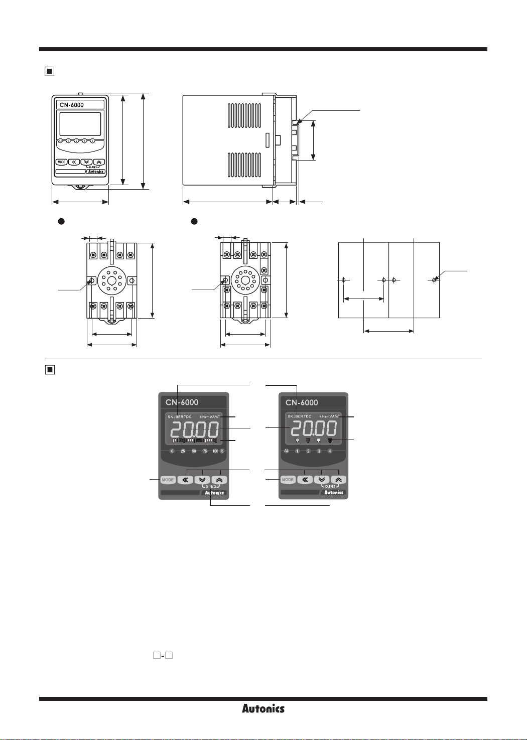
Dimensions
'l
I CN-6000
A
I
80
85
Q
@@
~,~
I h lvta.l 1
50
~
8-pin socket 11-pin socket
• •
2-Ø4.5
8
Ir
•Ir
~
76
I~
2-Ø4.5
(unit: mm)
35mm DIN Rail
~
j
35.2
____J
~~~~~~~~~~
J
~
~~~~~~~~~~
80
8
20 3.3
- .
.
~
76
2-Ø4.5
40
40
50
40
50
Min. 51
Unit Description
⑧
②
①
③
⑥
⑤ ⑤
⑦
[ Transmission output model ] [ Alarm output model ]
Display part (selectable red, green, yellow)
①
●
Run mode: Displays current measured value.
●
Set mode: Displays parameters.
Unit display part (red)
②
Output scale bar: For transmission output mode, displays output as % by scale bars.
③
Alarm output indicator: Turns ON when the alarm output is on.
④
⑤
⑥
⑦
⑧
key: Used to enter parameter set mode, move to parameters, save SV and return to RUN mode.
(
1, 4, 3
D.IN3: Press the 4 and 3 keys for 3 sec at the same time, it operates the set function (alarm clear, display hold,
Input type (only for CN-
key: Used to change parameter SV.
zero-point adjustment) at [
610
DI-K
): Turns ON the selected temperature sensor type at [
□-□
( In case of thermocouple type, L, N, U, P types are not displayed.
In case of RTD type, RTD is displayed.)
].
②
④
IN-P
] parameter.
Q-6
Autonics
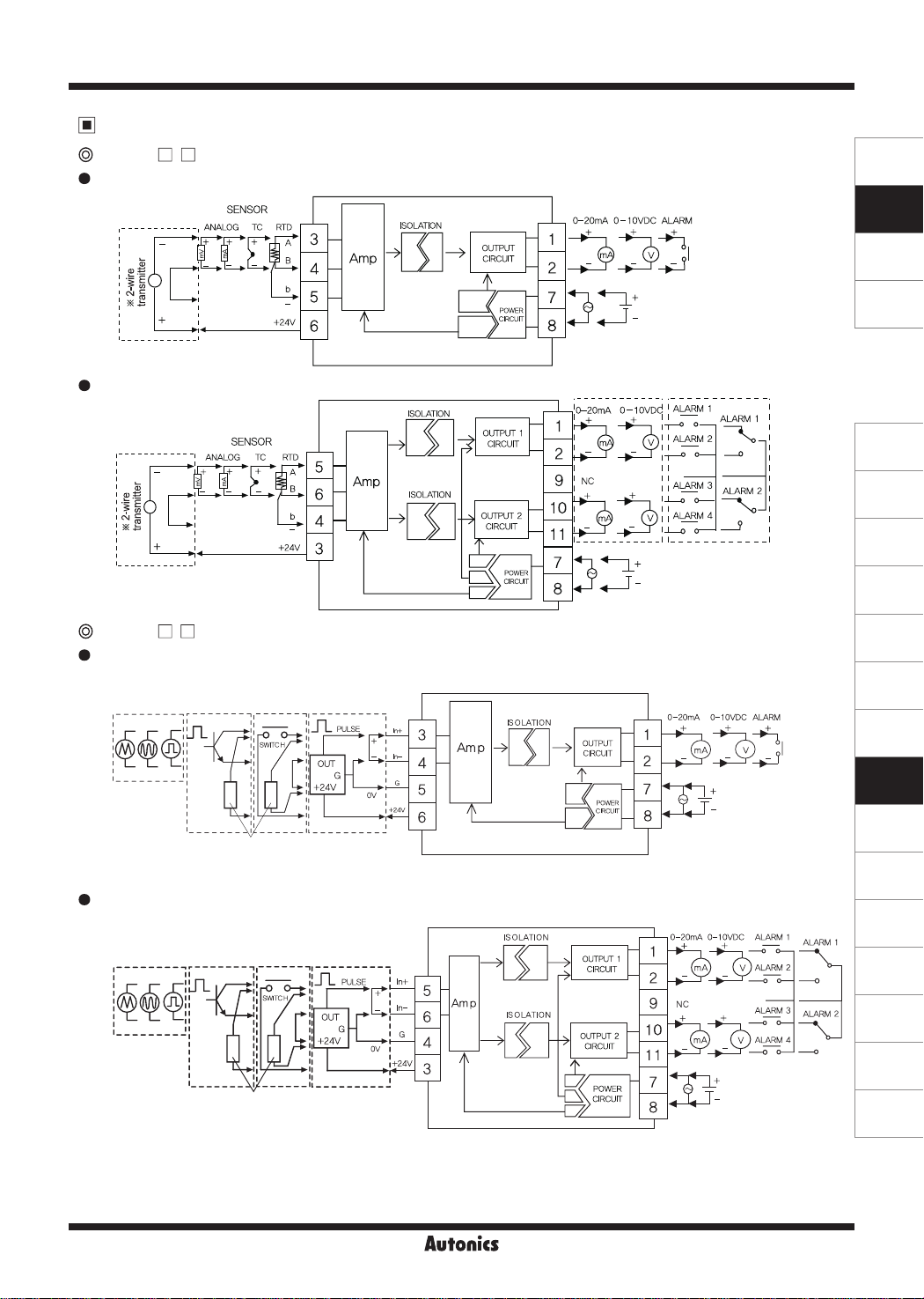
Connections
00
@
CN-610 -
8-pin
•
□□
Isolated Converter
SENSORS
CONTROLLERS
MOTION DEVICES
※
When using 2-wire transmitter,
short between no. 4 and 5 terminals.
11-pin
•
※
When using 2-wire transmitter,
short between no. 6 and 4 terminals.
@
CN-640 -
8-pin
•
11-pin
•
□□
Pulse input
1-
- - - - - - -
NPN open
---,r ---
collector
input
!~~~::
I
I
________
Pulse input
,--------~~-------,------,,----------
!~~~!:
I
I
I
'---------1
II
1:
I
※
Connect external resistance 10kΩ (over 1/2W) to
no. 3 and 6 terminals for NPN open collector input, or
no. 3 and 5 terminals for for contact input.
NPN open
collector
input
II
II
II
I
I
I
I
I
※
'----
Connect external resistance 10kΩ (over 1/2W) to
no. 5 and 3 terminals for NPN open collector input, or
no. 5 and 4 terminals for contact input.
- -
--
71-
,,_
Contact
input
- ----
Contact
input
-
71-
,,
1,
Voltage input
- - - - - - - -
Voltage
Voltage input
Voltage
+
-
_________ J
ISOLATION
➔
[3}]
1
0-20mA
I+
I -
____________
1
SOURCE
100-240VAC 50/60Hz,
24VDC
0-1
0VDC I ALARM 1
3+
:-:-,,-----;;
II
II
,-,-----<>
11 I
11 I
11
+
:~
11
3
l.l......<)-
11
SOURCE
100-240VAC 50/60Hz,
24VDC
ALARM
1 I
ALARM 2
~
-
0
ALARM 3 1
~
ALARM 4
__J
____________
SOURCE
100-240VAC 50/60Hz,
24VDC
SOURCE
100-240VAC 50/60Hz,
24VDC
SOFTWARE
I
:
I
:
1
I
1
(J)
Temperature
Controllers
(K)
SSRs
(L)
Power
Controllers
(M)
Counters
(N)
Timers
(O)
Digital
Panel Meters
(P)
Indicators
(Q)
Converters
(R)
Digital
Display Units
(S)
Sensor
Controllers
(T)
Switching
Mode Power
Supplies
(U)
Recorders
(V)
HMIs
(W)
Panel PC
(X)
Field Network
Devices
Autonics
Q-7
CN-6000 Series
Functions
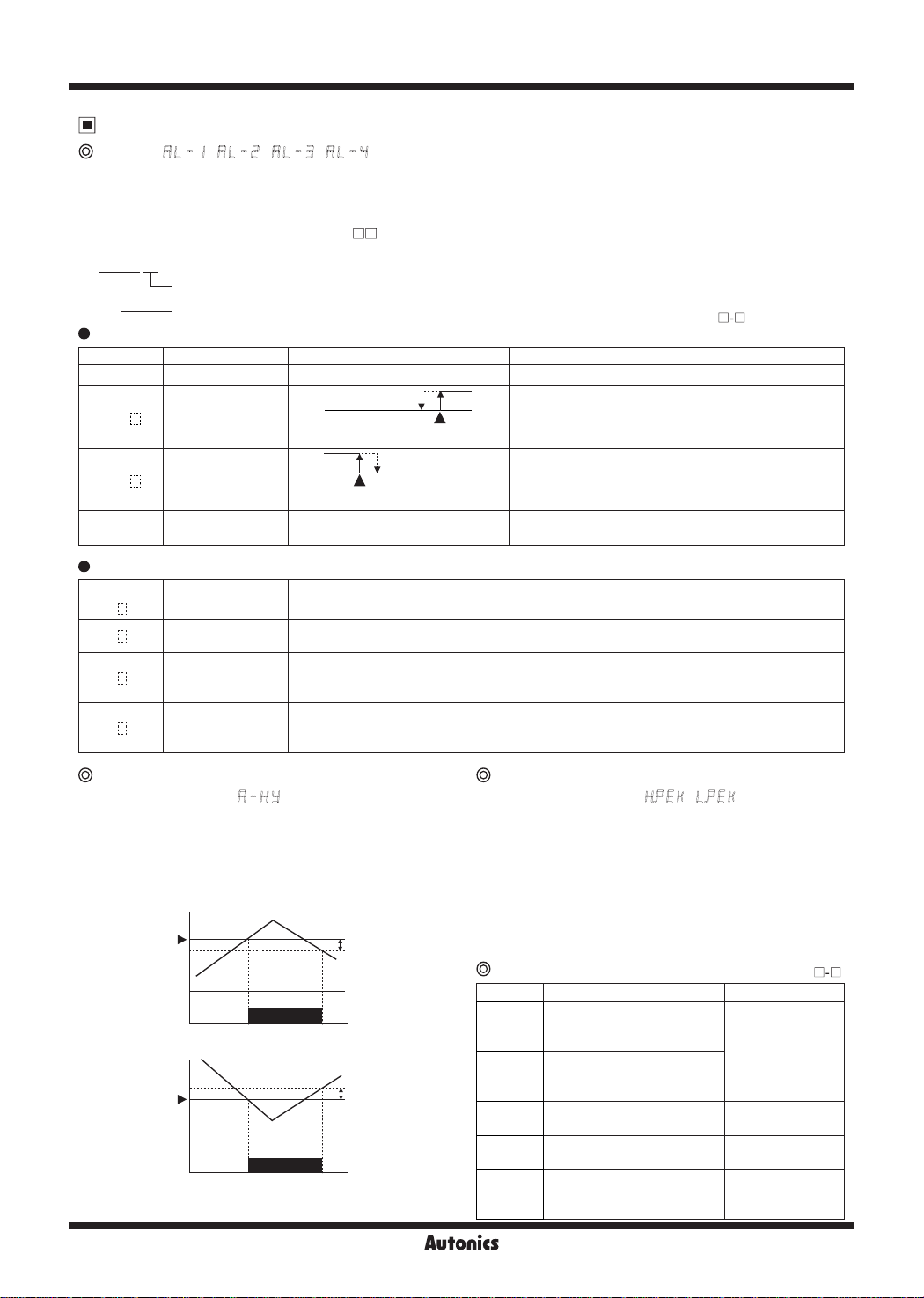
Alarm [ , , , ]
This product has 1, 2 or 4 alarms to operate individually when the value is too high or low.
Alarm function is set by the combination of alarm operation and alarm option.
To clear alarm, use digital input function (setting as
※
For the model without alarm output (CN-6
AlRE
-C1/C2/V1/V2), these parameters are not displayed.
□□
AT!A
Alarm op ion
Alarm operation
Alarm operation
•
Mode Name Alarm operation Description
AT)_
AT!
AT@
SBa_
Alarm option
•
Mode Name Descriptions
AT .A
AT .B
AT .C
AT .D
- -
High limit alarm
※
1
Low limit alarm
Sensor break alarm
Standard alarm If it is an alarm condition, alarm output is ON. Unless an alarm condition, alarm output is OFF.
Alarm latch
Standby sequence
Alarm latch and
standby sequence
-
If it is an alarm condition, alarm output is ON. Before clearing the alarm, an ON condition is
latched. (Holding the alarm output)
First alarm condition is ignored. From the second alarm condition, standard alarm operates.
When power is ON and it is an alarm condition, it is ignored. From the second alarm condition,
standard alarm operates.
If it is an alarm condition, it operates both alarm latch and standby sequence.
When power is ON and it is an alarm condition, it is ignored. From the second alarm condition,
alarm latch operates.
OFF
High limit alarm
value: 800
ON
PV
℃
H
Low limit alarm
value: 200
H
OFF
DI-K
for
ON
PV
℃
) or turn the power OFF and ON.
※
※
No alarm operation
PV ≥ alarm temperature, alarm is ON
PV ≤ alarm temperature, alarm is ON
It will be ON when it detects sensor disconnection.
Sensor break alarm does not have alarm option.
1: Only for CN-610
H: alarm output hysteresis
.
□-□
@ @
Alarm output hysteresis
[Program mode: ]
Set the interval of ON/OFF alarm output.
The set hysteresis is applied to AL1 to AL4 and it is as below.
E.g.) A HY 4
high limit alarm value: 800℃
low limit alarm value: 200℃
Q-8
High limit
alarm value
800℃
Low limit
alarm value
200℃
800℃
ON
200℃
ON
796℃
OFF
204℃
OFF
A-HY
A-HY
: 4
: 4
High/Low peak monitoring
[Monitoring mode: , ]
This function is to save high/low peak to check the invisible
abnormal condition of system at [
monitoring mode.
When the high/low peak is out of the temperature range,
it displays
HHHH
or
LLLL
.
To initialize high/low peak, press the 4, 3 keys at the
same time for 3 sec at [
hPEK
] or [
In this case, peak value is the present input value.
@
Error
Display Descriptions Troubleshooting
Flashes when measured
LLLL
HHHH
BURN
ERR2
sensor input is lower than the
temperature range.
Flashes when measured
sensor input is higher than
the temperature range
※
1
Flashes when the sensor is
break or not connected.
Flashes when there is error to
ERR
SV.
Flashes when [
※
1
and input type selection
switch setting are not same.
IN P
] or [
hPEK
lPEK
※
1: Only for CN-610
] setting
] in
lPEK
] .
□-□
When input is
moved within the
temperature range,
it is cleared.
Check temperature
sensor connection.
Check set conditions
and re-set it.
Check input type.
.
 Loading...