

Global LCD Panel Exchange Center
www.panelook.com
Product Specification
( V ) Preliminary Specification
( ) Final Specification
Module 19.0” WXGA Color TFT-LCD
AU OPTRONICS CORPORATION
M190PP01 V0
Model Name M190PP01 V0
Customer Date
Approved by
Prepared by Date
Flossie Chuang
Approved by
Sep. 1, 2008
Note: This Specification is subject to
change without notice.
document version 0.2 1/27
One step solution for LCD / PDP / OLED panel application: Datasheet, inventory and accessory!
Sean Chen
Desktop Display Business Group /
AU Optronics corporation
Sep. 1, 2008
www.panelook.com

Global LCD Panel Exchange Center
www.panelook.com
Product Specification
AU OPTRONICS CORPORATION
M190PP01 V0
Contents
1.0 Handling Precautions ................................................................................................................4
2.0 General Description ...................................................................................................................5
2.1 Display Characteristics..............................................................................................................5
2.2 Optical Characteristics ..............................................................................................................6
3.0 Functional Block Diagram...................................................................................................... 10
4.0 Absolute Maximum Ratings ................................................................................................... 11
4.1 TFT LCD Module .....................................................................................................................11
4.2 Backlight Unit...........................................................................................................................11
4.3 Absolute Ratings of Environment............................................................................................11
5.0 Electrical Characteristics ....................................................................................................... 12
5.1 TFT LCD Module .................................................................................................................... 12
5.1.1 Power Specification............................................................................................................. 12
5.1.2 Signal Electrical Characteristics.......................................................................................... 12
5.2 Backlight Unit ........................................................................................................................ 13
6.0 Signal Characteristic............................................................................................................... 14
6.1 Pixel Format Image ................................................................................................................ 14
6.2 Signal Description................................................................................................................... 15
6.3 Timing Characteristics ............................................................................................................ 17
6.3.1 Safe mode: 640×480@60Hz; .......................................................................................... 17
6.3.2 Native mode: .................................................................................................................... 18
(1) 1440×900@60Hz – Reduce Blanking................................................................................. 18
(2) 800×600@60Hz................................................................................................................... 19
6.4 EEPROM Memory Placement – 4K ....................................................................................... 20
6.5 Power ON/OFF Sequence ..................................................................................................... 21
7.0 Mode States ............................................................................................................................. 22
7.1 Kick-Off Condition................................................................................................................... 22
7.2 BIST Mode .............................................................................................................................. 22
7.3 Low Power Mode.................................................................................................................... 23
7.4 Error Mode (Failure Detection Mode) .................................................................................... 23
8.0 Connector & Pin Assignment ................................................................................................ 24
8.1 TFT LCD Module .................................................................................................................... 24
8.1.1 Pin Assignment ................................................................................................................ 24
8.2 Backlight Unit.......................................................................................................................... 25
8.2.1 Signal for Lamp connector............................................................................................... 25
9.0 Reliability Test ...........................................................................................................
10.0 Shipping Label ....................................................................................................................... 27
11.0 Mechanical Characteristics .................................................................................................28
document version 0.2 2/27
One step solution for LCD / PDP / OLED panel application: Datasheet, inventory and accessory!
.............. 26
www.panelook.com
Global LCD Panel Exchange Center
www.panelook.com
Product Specification
AU OPTRONICS CORPORATION
M190PP01 V0
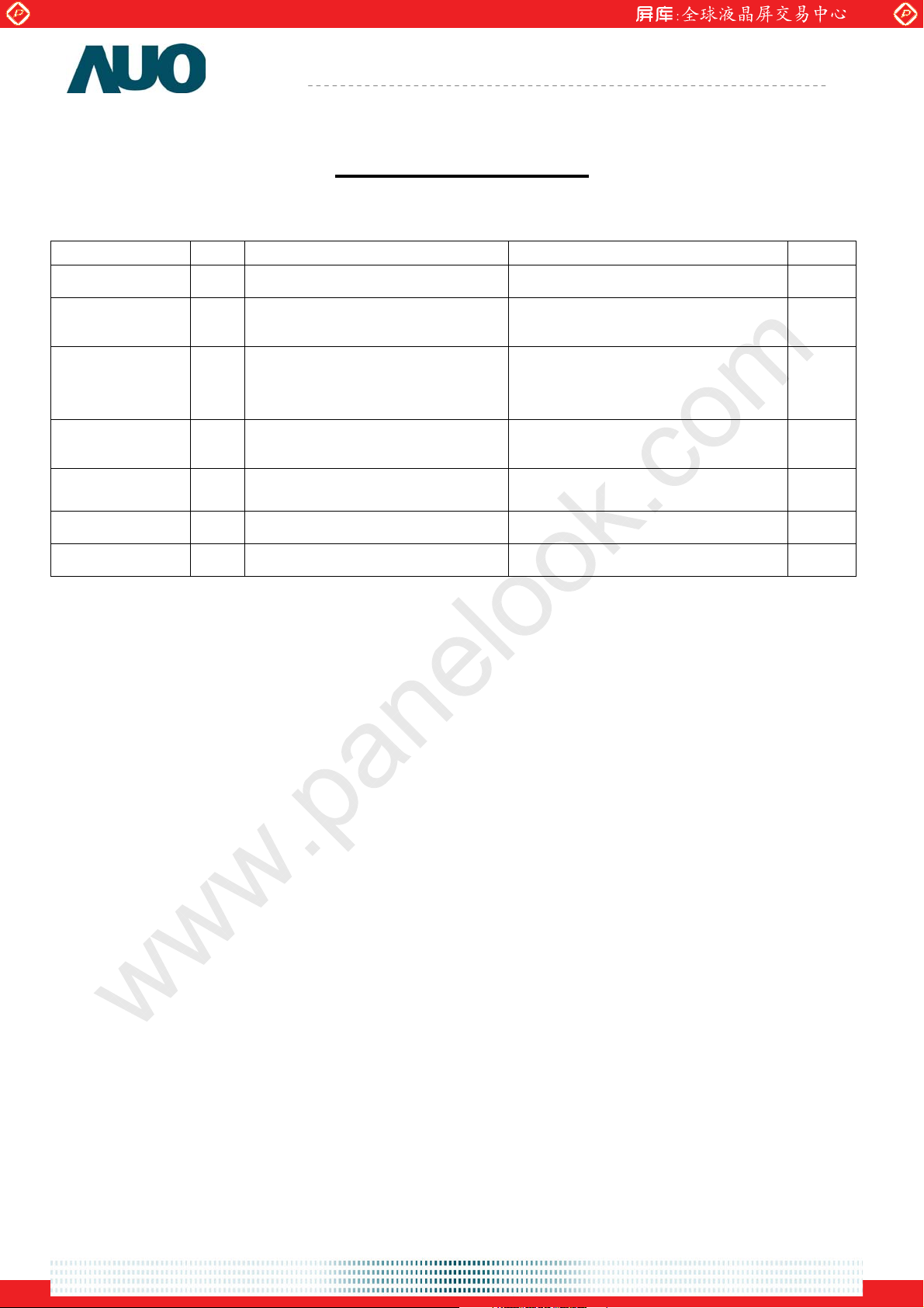
Record of Revision
Version and Date Page Old description New Description Remark
0.1 2008/02/13 All First Edition for Customer -
0.2 2008/09/01 12 5.1.1 Power Specification
IDD: 0.9A(typ); PDD: 4.5W(typ)
13 5.2 Backlight Unit
FCFL: 50 [KHz]
VCFL: 771 [Volt]rms
21 6.5 Power On/Off Sequence Re-define the signal definitions and
20 6.4 EEPROM Memory Placement –
16K
5.1.1 Power Specification
IDD: 1.0A(typ); PDD: 5.0W(typ)
5.2 Backlight Unit
FCFL: 55 [KHz]
VCFL: 718 [Volt]rms
1. Change from 16K to 4K
2. Update the memory placement
values
Modify
Modify
Modify
Modify
document version 0.2 3/27
One step solution for LCD / PDP / OLED panel application: Datasheet, inventory and accessory!
www.panelook.com

Global LCD Panel Exchange Center
www.panelook.com
Product Specification
AU OPTRONICS CORPORATION
M190PP01 V0
1.0 Handling Precautions
1) Since front polarizer is easily damaged, pay attention not to scratch it.
2) Be sure to turn off power supply when inserting or disconnecting from input connector.
3) Wipe off water drop immediately. Long contact with water may cause discoloration or
spots.
4) When the panel surface is soiled, wipe it with absorbent cotton or other soft cloth.
5) Since the panel is made of glass, it may break or crack if dropped or bumped on hard
surface.
6) Since CMOS LSI is used in this module, take care of static electricity and insure human
earth when handling.
7) Do not open or modify the Module Assembly.
8) Do not press the reflector sheet at the back of the module to any directions.
9) In case if a Module has to be put back into the packing container slot after once it was
taken out from the container, do not press the center of the CCFL reflector edge.
Instead, press at the far ends of the CCFL Reflector edge softly. Otherwise the TFT
Module may be damaged.
10) At the insertion or removal of the Signal Interface Connector, be sure not to rotate nor
tilt the Interface Connector of the TFT Module.
11) After installation of the TFT Module into an enclosure, do not twist nor bend the TFT
Module even momentary. At designing the enclosure, it should be taken into
consideration that no bending/twisting forces are applied to the TFT Module from
outside. Otherwise the TFT Module may be damaged.
12) Cold cathode fluorescent lamp in LCD contains a small amount of mercury. Please follow
local ordinances or regulations for disposal.
13) Small amount of materials having no flammability grade is used in the LCD module. The LCD
module should be supplied by power complied with requirements of Limited Power Source
(IEC60950 or UL1950), or be applied exemption.
14) The LCD module is designed so that the CCFL in it is supplied by Limited Current Circuit
(IEC60950 or UL1950). Do not connect the CCFL in Hazardous Voltage Circuit.
document version 0.2 4/27
One step solution for LCD / PDP / OLED panel application: Datasheet, inventory and accessory!
www.panelook.com
Global LCD Panel Exchange Center
www.panelook.com
Product Specification
AU OPTRONICS CORPORATION
M190PP01 V0
2.0 General Description
This specification applies to the 19 inch-wide Color a-Si TFT-LCD Module M190PP01 V0.
The display supports the WXGA (1440(H) x 900(V)) screen format and 16.7M colors (RGB
6-bits + Hi-FRC data).
All input signals are 1 Lane Displayport interface compatible.
This module doesn’t contain an inverter board for backlight.
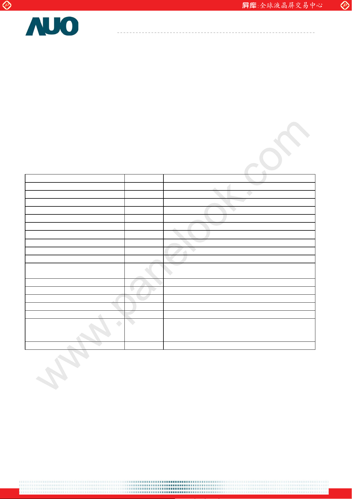
2.1 Display Characteristics
The following items are characteristics summary on the table under 25 к condition:
ITEMS Unit SPECIFICATIONS
Screen Diagonal [mm] 482.6 (19.0”Wide)
Active Area [mm] 408.24 (H) x 255.15(V)
Pixels H x V 1440(x3) x 900
Pixel Pitch [mm] 0.2835(per one triad) x 0.2835
Pixel Arrangement R.G.B. Vertical Stripe
Display Mode TN Mode, Normally White
White Luminance ( Center ) [cd/m2]
300 cd/m
Contrast Ratio 1000 (Typ.)
Optical Response Time [msec] 5ms (Typ., on/off)
Nominal Input Voltage VDD [Volt] +5.0 V
Power Consumption
[Watt] 24 W (Typ.)
(VDD line + CCFL line)
Weight [Grams] 2120 (Typ.)
Physical Size [mm] 428.0(W) x 278.0(H) x 18.5(D) (Typ)
Electrical Interface 1 Lane Displayport (HDCP v1.3 ; EDID1.4)
Support Color 16.7M colors (RGB 6-bit + Hi_FRC )
Surface Treatment Anti-Glare, 3H
Temperature Range
Operating
Storage (Shipping)
o
C]
[
o
C]
[
0 to +50
-20 to +60
RoHS Compliance RoHS Compliance
2 @ 6.5mA
(Typ)
document version 0.2 5/27
One step solution for LCD / PDP / OLED panel application: Datasheet, inventory and accessory!
www.panelook.com
Global LCD Panel Exchange Center
www.panelook.com
Product Specification
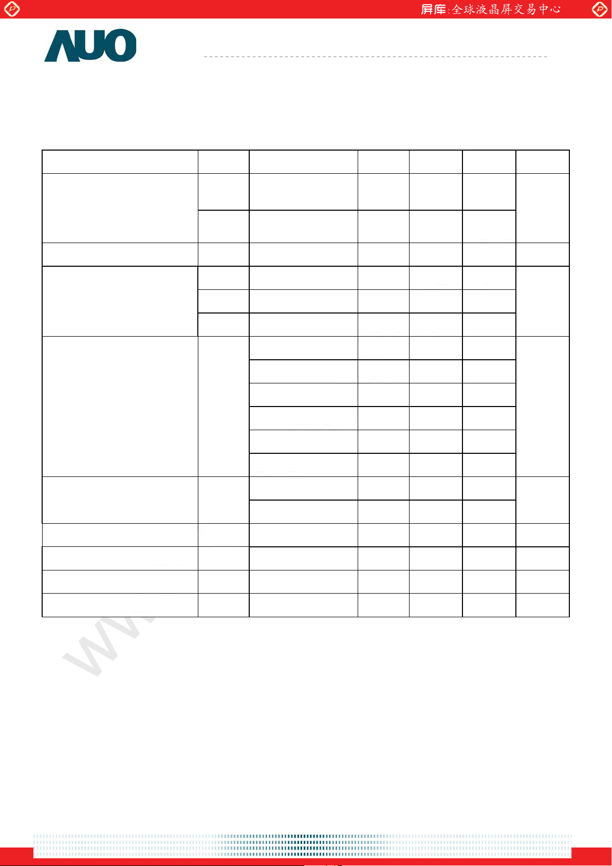
2.2 Optical Characteristics
The optical characteristics are measured under stable conditions at 25к.
Viewing Angle
Contrast ratio Normal Direction 600 1000 -
Response Time
AU OPTRONICS CORPORATION
Item Unit Conditions Min. Typ. Max. Note
[degree]
[degree]
[degree]
[degree]
Horizontal (Right)
CR = 10 (Left)
Vertical (Up)
CR = 10 (Down)
150 170
140 160
[msec] Raising Time - 3.4 7.4
[msec] Falling Time - 1.6 2.6
[msec] Raising + Falling - 5 10
M190PP01 V0
-
1,3
-
-
1
1,2
Color / Chromaticity
Coordinates (CIE)
Color Coordinates (CIE)
Red x
Red y
Green x
Green y
Blue x
Blue y
White x
0.620 0.650 0.680
0.310 0.340 0.370
0.260 0.290 0.320
0.580 0.610 0.640
0.120 0.150 0.180
0.040 0.070 0.100
0.283 0.313 0.343
White
White y
0.299 0.329 0.359
Central Luminance (IL=6mA) [cd/m2] 240 300 - 1
Luminance Uniformity
Crosstalk (At 60Hz)
Flicker
[%] 75 80 - 1,4
[%] 1.5 1,5
dB -20 1,6
1
1
document version 0.2 6/27
One step solution for LCD / PDP / OLED panel application: Datasheet, inventory and accessory!
www.panelook.com
Global LCD Panel Exchange Center
www.panelook.com
Product Specification
AU OPTRONICS CORPORATION
M190PP01 V0
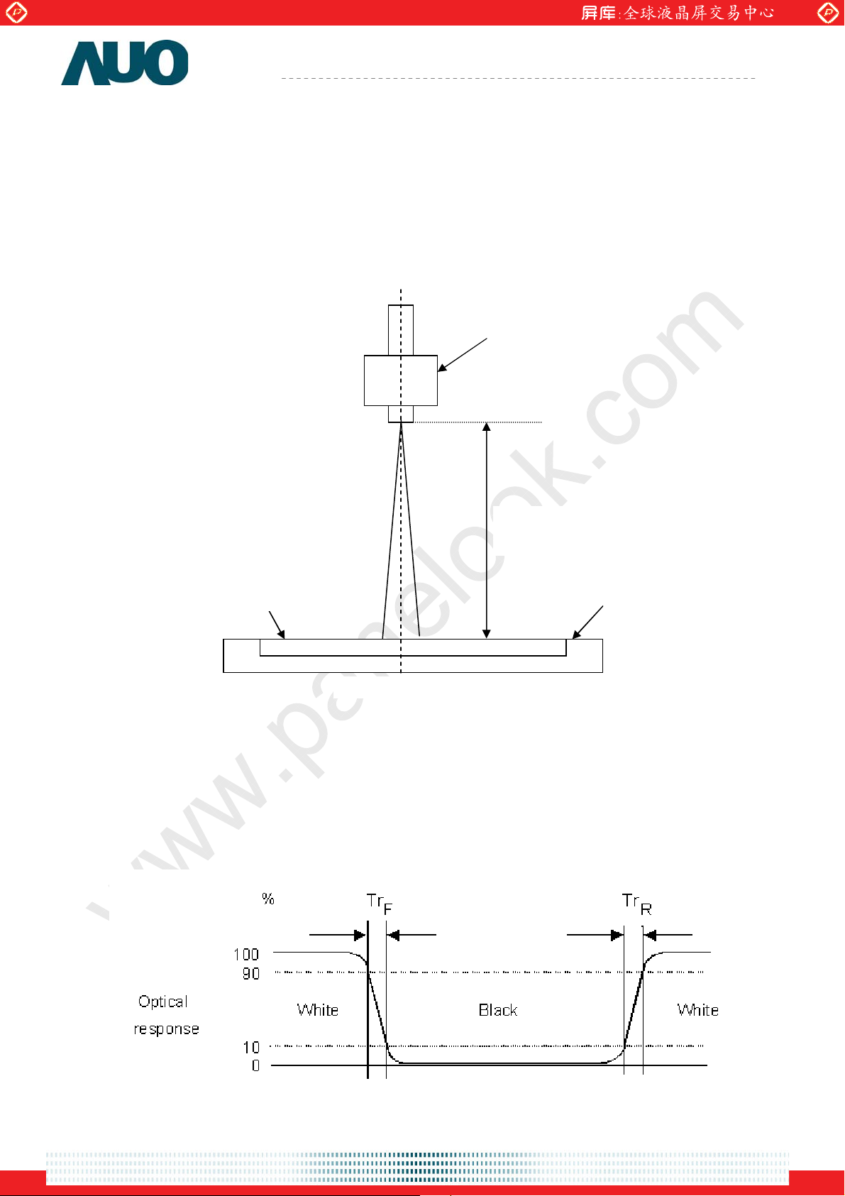
Note 1: Measurement method
The LCD module should be stabilized at given temperature for 30 minutes to avoid abrupt
temperature change during measuring. In order to stabilize the luminance, the measurement
should be executed after lighting Backlight for 30 minutes in a stable, windless and dark room. ʳ
Photo detector
Measurement
Note 2: Definition of Response time measured by Westar TRD-100A
The output signals of photodetector are measured when the input signals are changed from
“Black” to “White” (rising time), and from “White” to “Black ”(falling time), respectively. The
response time is interval between the 10% and 90% of amplitudes.
LCD Panel
Center of the screen
Distance
TFT-LCD Module
document version 0.2 7/27
One step solution for LCD / PDP / OLED panel application: Datasheet, inventory and accessory!
www.panelook.com
Global LCD Panel Exchange Center
www.panelook.com
Product Specification
M190PP01 V0
AU OPTRONICS CORPORATION
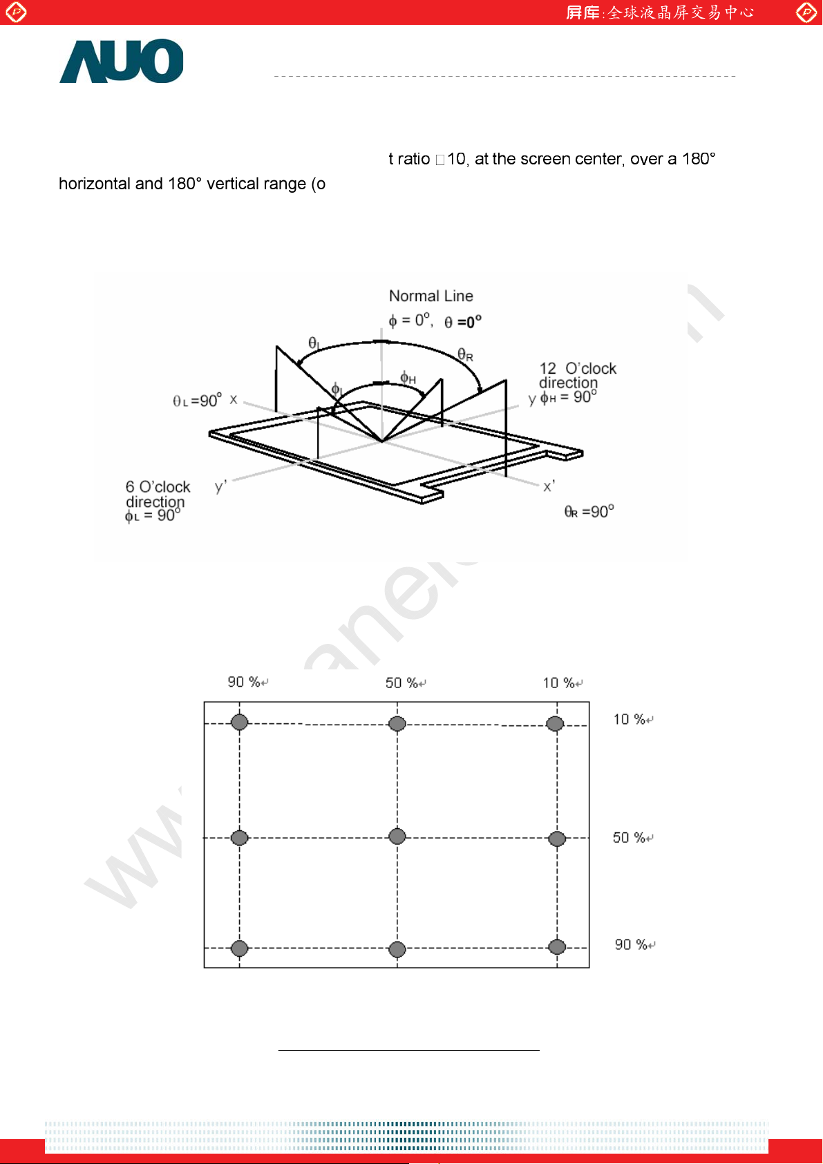
Note 3: Definition of viewing angle: measured by TOPCON SR-3
Viewing angle is the measurement of contras
horizontal and 180° vertical range (off-normal viewing angles). The 180° viewing angle range is
broken down as follows; 90° (θ) horizontal left and right and 90° (Φ) vertical, high (up) and low
(down). The measurement direction is typically perpendicular to the display surface with the
screen rotated about its center to develop the desired measurement viewing angle.
Note 4: Luminance uniformity of these 9 points is defined as below measured by TOPCON
SR-3
9)-(1 points 9in LuminanceMinimum
Uniformity =
9)-(1 Points 9in LuminanceMaximum
One step solution for LCD / PDP / OLED panel application: Datasheet, inventory and accessory!
document version 0.2 8/27
www.panelook.com

Global LCD Panel Exchange Center
www.panelook.com
Product Specification
Note 5: Crosstalk is defined as below : measured by TOPCON SR-3
CT = | YB – YA | / YA Ø 100 (%)
Where
YA = Luminance of measured location without gray level 0 pattern (cd/m2)
YB = Luminance of measured location with gray level 0 pattern (cd/m2)
AU OPTRONICS CORPORATION
M190PP01 V0
Note 6: Test Paterm: Subchecker Pattern measured by TOPCON SR-3
R G B R G B
Gray Level = L127
R G B R G B
R G B R G B
Gray Level = L0
Method: Record dBV & DC value with (WESTAR)TRD-100
Amplitude
DC
AC
Time
Hz) 30Level(at AC
log20(dB)Flicker =
Level DC
document version 0.2 9/27
One step solution for LCD / PDP / OLED panel application: Datasheet, inventory and accessory!
www.panelook.com

Global LCD Panel Exchange Center
www.panelook.com
Product Specification
AU OPTRONICS CORPORATION
M190PP01 V0
3.0 Functional Block Diagram
The following diagram shows the functional block of the 19.0 inch-wide Color TFT-LCD
Module:
DC/DC
Converter
Power
Signal
Gamma
Correction
1Lane DP
Input
Connector
Receiver
Process
DP
Image
Over
Driver
GNSS gm58026
I/F PCB Interface:
JAE FI-XB30SSL-HF15 or compatible
Timing
Controller
Y-Driver IC
DC POWER
-
TFT-LCD 1440(*3)*900 pixels
(8 bits display)
4 CCFL
Inverte
Mating Type:
FI-X30HL-T (Locked Type)
FI-X30S-H (Unlocked Type)
document version 0.2 10/27
One step solution for LCD / PDP / OLED panel application: Datasheet, inventory and accessory!
www.panelook.com

Global LCD Panel Exchange Center
www.panelook.com
Product Specification
4.0 Absolute Maximum Ratings
Absolute maximum ratings of the module is as following:
4.1 TFT LCD Module
Item Symbol Min Max Unit
Logic/LCD Drive Voltage
4.2 Backlight Unit
Item Symbol Min Max Unit Conditions
CCFL Current ICFL 2.0 8.0 [mA] rms Note 1,2
4.3 Absolute Ratings of Environment
AU OPTRONICS CORPORATION
Conditions
VDD -0.3 5.5 [Volt] Note 1,2
M190PP01 V0
Item Symbol Min. Max. Unit Conditions
Operating Temperature TOP 0 +50 [oC]
Operation Humidity HOP 5 90 [%RH]
Storage Temperature TST -20 +60 [oC]
Storage Humidity HST
5 90
[%RH]
Note 1: With in Ta (25к )
Note 2: Permanent damage to the device may occur if exceed maximum values
Note 3: For quality perfermance, please refer to AUO IIS(Incoming Inspection Standard).
Note 3
Operating Range Storage Range
document version 0.2 11/27
One step solution for LCD / PDP / OLED panel application: Datasheet, inventory and accessory!
www.panelook.com

Global LCD Panel Exchange Center
www.panelook.com
Product Specification
5.0 Electrical Characteristics
5.1 TFT LCD Module
5.1.1 Power Specification
Input power specifications are as follows;
Symbol Parameter Min Typ Max Units
VDD
IDD VDD current - 1.0 1.4 [A]
PDD VDD Power - 5.0 7.7 [Watt]
VDDrp
AU OPTRONICS CORPORATION
Logic/LCD Drive
Voltage
Allowable logic/LCD
Drive Ripple Voltage
Condition
4.5 5.0 5.5 [Volt] f10%
at 60Hz
- - 200
[mV]
p-p
M190PP01 V0
VDD=5V , All Black Pattern,
VDD=5V , All Black Pattern,
at 60Hz
VDD=5.0, All pattern at 60Hz
5.1.2 Signal Electrical Characteristics
Input signals shall be one lane Displayport operated at 2.7Gbps to support 1440
per color.
It is recommended to refer the specifications of VESA Displayport1.1 in details.
900 @ 8 bits
document version 0.2 12/27
One step solution for LCD / PDP / OLED panel application: Datasheet, inventory and accessory!
www.panelook.com

Global LCD Panel Exchange Center
www.panelook.com
Product Specification
M190PP01 V0
AU OPTRONICS CORPORATION
5.2 Backlight Unit
Parameter guideline for CCFL Inverter is under stable conditions at 25
Parameter Min. Typ. Max. Unit Condition
CCFL Operation Current(ICFL) 3.0 6.5 8.0 [mA] rms
CCFL Frequency(FCFL) 40 55 80 [KHz]
#$%
!
CCFL Ignition Voltage(ViCFL,
CCFL Ignition Voltage(ViCFL, Ta= 25
CCFL Operation Voltage (VCFL) -
"
1700 - - [Volt] rms
%
$
1250 - - [Volt] rms
718
(@ 6.5mA)
848
[Volt] rms
CCFL Power Consumption(PCFL) - 20.04 22.04 [Watt]
Note 2
Note 3,4
Note 5
Note 6
Note 6
CCFL Life Time(LTCFL) 40,000 50,000 - [Hour]
Note 7
Note 1: Typ. are AUO recommended design points.
*1 All of characteristics listed are measured under the condition using the AUO test inverter.
*2 In case of using an inverter other than listed, it is recommended to check the inverter carefully.
Sometimes, interfering noise stripes appear on the screen, and substandard luminance or
flicker at low power may happen.
*3 In designing an inverter, it is suggested to check safety circuit very carefully. Impedance of
CCFL, for instance, becomes more than 1 [M ohm] when CCFL is damaged.
*4 Generally, CCFL has some amount of delay time after applying kick-off voltage. It is
recommended to keep on applying kick-off voltage for 1 [Sec] until discharge.
*5 Reducing CCFL current increases CCFL discharge voltage and generally increases CCFL
discharge frequency. So all the parameters of an inverter should be carefully designed so as
not to produce too much leakage current from high-voltage output of the inverter.
Note 2: It should be employed the inverter which has “Duty Dimming”, if IRCFL is less than 3mA.
Note 3: CCFL discharge frequency should be carefully determined to avoid interference between inverter
and TFT LCD.
Note 4: The frequency range will not affect to lamp life and reliability characteristics.
Note 5: CCFL inverter should be able to give out a power that has a generating capacity of over 1,700
voltage. Lamp units need 1,700 voltage minimum for ignition.
Note 6: The variance of CCFL power consumption is ±10%. Calculator value for reference (ISCFL ×
VCFL × 4 = PCFL)
Note 7: Definition of life: brightness becomes 50%. The typical life time of CCFL is under the condition at
6.5 mA lamp current.
document version 0.2 13/27
One step solution for LCD / PDP / OLED panel application: Datasheet, inventory and accessory!
www.panelook.com

Global LCD Panel Exchange Center
www.panelook.com
Product Specification
AU OPTRONICS CORPORATION
M190PP01 V0
6.0 Signal Characteristic
6.1 Pixel Format Image
Following figure shows the relationship of the input signals and LCD pixel format.
document version 0.2 14/27
One step solution for LCD / PDP / OLED panel application: Datasheet, inventory and accessory!
www.panelook.com

Global LCD Panel Exchange Center
V
V
V
y
p
A
A
www.panelook.com
Product Specification
AU OPTRONICS CORPORATION
M190PP01 V0
6.2 Signal Description
The following table shows the pin assignment for this module.
PIN # NAME In/Out Min. Typ. Max. Unit DESCRIPTION
1
2
3
4 N/C
5 N/C
6 GND GND Power Ground
7 GND GND Power Ground
8 GND GND Power Ground
9 LPM Out Low Power Mode
LCD In 4.5 5 5.5 [Volt] LCD Power
LCD In 4.5 5 5.5 [Volt] LCD Power
LCD In 4.5 5 5.5 [Volt] LCD Power
10 BKL On/Off Out Inverter On/Off: 3.3V On; 0V Off
11 Invt Dim Out PWM for Inverter
12 Keypad In LBADC Button detect
13 3.3V ref Out Keypad Ref Voltage
14 3.3V GND GND 3.3V Ke
15 LED 1 Out LED 1(Green) Control
16 LED 2 Out LED 2(Orange) Control
17 H GND In High Speed GND, DP Interface
18 Lane 1 N In DP Main Link CH-N
19 Lane 1 P In DP Main Link CH-P
20 H GND In DP Ground
21 Lane 0 N In DP Main Link CH-N
22 Lane 0 P In DP Main Link CH-P
23 H GND In High Speed GND, DP Interface
24
25
26 H GND In High Speed GND, DP Interface
27 HPD Out Hot Plug Detect
UX CH P In/Out DP AUX CH-P
UX CH N In/Out DP AUX CH-N
a ref GND
28 N/C
29 N/C
30 HVS In High Voltage Stress Control
One step solution for LCD / PDP / OLED panel application: Datasheet, inventory and accessory!
document version 0.2 15/27
www.panelook.com

Global LCD Panel Exchange Center
V
www.panelook.com
Note1: Start from left side
Product Specification
AU OPTRONICS CORPORATION
Connector
M190PP01 V0
HVS
1
LCD
document version 0.2 16/27
One step solution for LCD / PDP / OLED panel application: Datasheet, inventory and accessory!
www.panelook.com

Global LCD Panel Exchange Center
www.panelook.com
Product Specification
AU OPTRONICS CORPORATION
M190PP01 V0
6.3 Timing Characteristics
This module only support two modes – Safe mode and Native mode.
6.3.1 Safe mode: 640×480@60Hz;
GPU always detects the panel native resolution through the AUX CH as stored in the EDID and
scales the desktop output to fit into the LCD native video format. However, some data formats
may not be supported because the driver is damaged or not loaded. The LCD needs to display
the safe mode display either from the top left corner of the screen, centered on the active center
of LCD screen or Scaled to fill screen.
At this time it is envisioned most controllers will scale the image to full or near full screen.
document version 0.2 17/27
One step solution for LCD / PDP / OLED panel application: Datasheet, inventory and accessory!
www.panelook.com

Global LCD Panel Exchange Center
www.panelook.com
Product Specification
6.3.2 Native mode:
(1) 1440×900@60Hz – Reduce Blanking
Format: 1440 x 900 @ 60 Hz - Reduced Blanking
VESA CVT Name: 1.30MA-R
HOR PIXELS 1,440
VER PIXE LS 900
HOR FREQUENCY 55.469
ACTUAL VER FREQUENCY 59.901
PIXEL CLOCK 88.750
CHARACTER WIDTH 90.141
SCAN TYPE NON-INT
ASPECT RATIO 16:10
HSYNC POLARITY POSITIVE
VSYNC POL ARITY NEGATIVE
HOR TOTAL 18.028
HOR ADDR 16.225
AU OPTRONICS CORPORATION
PIXELS
LINES
kHz
Hz
MHz
ns
us
us
200
180
CHARS
CHARS
1,600
1,440
1
PIXELS
8
PIXELS
PIXELS
PIXELS
M190PP01 V0
HOR BLANK 1.803
HOR BLANK+MARGIN 1.803
PREDICTED H BLANK DUTY CYCLE 24.598
(from GTF blanki ng formula)
ACTUAL HOR BLANK DUTY CYCLE 10.000
ACT. HOR BLNK+MARGIN DUTY CYCLE 10.000
H LEFT MARGIN 0.000
H FRONT PORCH 0.541
HOR SYNC 0.361
H BACK PORCH 0.901
H RIGHT MARGIN 0.000
VER TOTAL 16.694
VER ADDR 16.225
VER BLANK 0.469
V TOP MARGIN 0.000
V FRONT PORCH 54.085
VER SYNC 108.169
V BACK PORCH 306.479
V BOTTOM MARGIN 0.000
us
us
%
%
%
us
us
us
us
us
ms
ms
ms
us
us
us
us
us
20
20
0
6
4
10
0
CHARS
CHARS
CHARS
CHARS
CHARS
CHARS
CHARS
160
160
926.0
900.0
26.0
0.0
3.0
6.0
17.0
0.0
0
48
32
80
0
PIXELS
PIXELS
PIXELS
PIXELS
PIXELS
PIXELS
PIXELS
LINES
LINES
LINES
LINES
LINES
LINES
LINES
LINES
document version 0.2 18/27
One step solution for LCD / PDP / OLED panel application: Datasheet, inventory and accessory!
www.panelook.com

Global LCD Panel Exchange Center
www.panelook.com
(2) 800×600@60Hz
Product Specification
AU OPTRONICS CORPORATION
M190PP01 V0
document version 0.2 19/27
One step solution for LCD / PDP / OLED panel application: Datasheet, inventory and accessory!
www.panelook.com

Global LCD Panel Exchange Center
www.panelook.com
Product Specification
AU OPTRONICS CORPORATION
M190PP01 V0
6.4 EEPROM Memory Placement – 4K
Address Name 7 6 5 4 3 2 1 0
0
Customer Used Customer Definition
255
256
T-CON Used T-CON Definition
383
384 Mode Enable 2
385 Coef_11 value [7:0]
386
387
388 Offset 1 value [7:0]
389 Offset 1 value [9:8]
390
: ʳ
509 Checksum[7:0]
510 Checksum[15:8]
511
Color Matrix
Reserved
CM
enable
ʳ ʳ ʳ ʳ ʳ ʳ ʳ
ʳ ʳ ʳ ʳ ʳ ʳ ʳ
Coef_11 value [10:8]
Color Matrix setting Coef_21~33 [8][11]
Color Matrix setting [2][10]
CHECKSUM_O
K
document version 0.2 20/27
One step solution for LCD / PDP / OLED panel application: Datasheet, inventory and accessory!
www.panelook.com

Global LCD Panel Exchange Center
www.panelook.com
Product Specification
AU OPTRONICS CORPORATION
M190PP01 V0
6.5 Power ON/OFF Sequence
Vin power and lamp on/off sequence is as follows. Interface signals are also shown in the
chart. Signals from any system shall be Hi-Z state or low level when Vin is off.
Symbol
Min Max
T0 0.5 25 [ms]
T1 - 25 [ms]
T2 - 50 [ms]
T3 500 - [ms]
T4 200 - [ms]
T5 - 50 [ms]
T6 - 1000 [ms]
T7 1000 - [ms]
Values
Unit
document version 0.2 21/27
One step solution for LCD / PDP / OLED panel application: Datasheet, inventory and accessory!
www.panelook.com

Global LCD Panel Exchange Center
www.panelook.com
Product Specification
AU OPTRONICS CORPORATION
M190PP01 V0
7.0 Mode States
7.1 Kick-Off Condition
While operating the LCD module, it will start from checking the AC power status. Then, it will
receive MCCS command SET_POWER “Sink Control register of DPCD (Displayport
Configuration Data)”
Base on the following diagram to do the mode states switch.
7.2 BIST Mode
BIST mode will activate when video cable is disconnected from PC and power up button
activated. The interval time between each pattern is 2 sec.
document version 0.2 22/27
One step solution for LCD / PDP / OLED panel application: Datasheet, inventory and accessory!
www.panelook.com

Global LCD Panel Exchange Center
www.panelook.com
Product Specification
AU OPTRONICS CORPORATION
M190PP01 V0
7.3 Low Power Mode
Low power mode (LowPwr) will be kicked off follow the following conditions:
1. Check AC power status
2. Receive MCCS command SET_POWER
3. Main link power down, wait 15sec and enter to the LowPwr (low power-down state)
4. Turn-on the LED2 ON
5. Turn off LCD Backlight
7.4 Error Mode (Failure Detection Mode)
When LCD inputs detect abnormal (non-VESA standard timing), LCD screen should display
black.
document version 0.2 23/27
One step solution for LCD / PDP / OLED panel application: Datasheet, inventory and accessory!
www.panelook.com

Global LCD Panel Exchange Center
www.panelook.com
Product Specification
AU OPTRONICS CORPORATION
M190PP01 V0
8.0 Connector & Pin Assignment
Physical interface is described as for the connector on module.
These connectors are capable of accommodating the following signals and will be following
components.
8.1 TFT LCD Module
Connector Name / Designation Interface Connector / Interface card
Manufacturer JAE or compatible
Type Part Number FI-XB30SSL-HF15
Mating Housing Part Number
FI-X30HL-T (Locked Type)
FI-X30S-H (Unlocked Type)
8.1.1 Pin Assignment
Pin# Signal Name Pin# Signal Name
1 VLCD 2 VLCD
3 VLCD 4 N/C
5 N/C 6 GND
7 GND 8 GND
9 LPM 10 BKL On/Off
11 Invt Dim 12 Keypad
13 3.3v ref 14 3.3v GND
15 LED 1 16 LED 2
17 H_GND 18 Lane 1_N
19 Lane 1_P 20 H_GND
21 Lane 0_N 22 Lane 0_P
23 H_GND 24 AUX_CH_P
25 AUX_CH_N 26 H_GND
27 HPD 28 N/C
29 N/C 30 HVS
document version 0.2 24/27
One step solution for LCD / PDP / OLED panel application: Datasheet, inventory and accessory!
www.panelook.com

Global LCD Panel Exchange Center
www.panelook.com
Product Specification
AU OPTRONICS CORPORATION
M190PP01 V0
8.2 Backlight Unit
Physical interface is described as for the connector on module. These connectors are capable of
accommodating the following signals and will be following components.
Connector Name / Designation Lamp Connector / Backlight lamp
Manufacturer
Type Part Number
Mating Type Part Number
YEON HO
35001HS-02L
35001WR-02LP or equivalent
8.2.1 Signal for Lamp connector
Connector No. Pin No. Input Color Function
1 Hot1 Blue High Voltage (Lamp 1)
2 Cold1
1 Hot2 Pink High Voltage (Lamp 2)
2 Cold2
1 Hot1 Blue High Voltage (Lamp 3)
2 Cold1 Black Low Voltage (Lamp 3)
1 Hot2 Pink High Voltage (Lamp 4)
2 Cold2 White Low Voltage (Lamp 4)
Upper
Lower
CN1
CN2
Connector No. Pin No. Input Color Function
CN3
CN4
Black Low Voltage (Lamp 1)
White Low Voltage (Lamp 2)
document version 0.2 25/27
One step solution for LCD / PDP / OLED panel application: Datasheet, inventory and accessory!
www.panelook.com

Global LCD Panel Exchange Center
www.panelook.com
Product Specification
9.0 Reliability Test
Environment test conditions are listed as following table.
Temperature Humidity Bias (THB) Ta= 5
High Temperature Operation
(HTO)
Low Temperature Operation (LTO) Ta=
High Temperature Storage (HTS) Ta=
Low Temperature Storage (LTS) Ta= -
Vibration Test
(Non-operation)
AU OPTRONICS CORPORATION
Items Required Condition
'
(
80%RH, 300hours
&
'
(
&
Ta= 5
Acceleration: 1.5 G
Wave: Half-sine
Frequency: 10 - 200 - 10 Hz
Sweep: 30 Minutes each Axis (X, Y, Z)
50%RH, 300hours
)
'
&
/ &
0 &
*
+,- .
(
& &
)
'
*
+,- .
(
& &
)
'
*
+,- .
(
& &
M190PP01 V0
Note
Acceleration: 50 G
Shock Test
(Non-operation)
Wave: Half-sine
Active Time: 20 ms
Direction: X,ʳY,ʳZ (one time for each Axis)
Drop Test Height: 60 cm, package test
Thermal Shock Test (TST) -20'/30min, 60'/30min, 100 cycles
On/Off Test On/10sec, Off/10sec, 30,000 cycles
Note:1
Contact Discharge: ± 8KV, 150pF(330Ω ) 1sec,
8 points, 25 times/ point.
ESD (ElectroStatic Discharge)
Note: 2
Air Discharge: ± 15KV, 150pF(330Ω ) 1sec
8 points, 25 times/ point.
Altitude Test
Operation:10,000 ft
Non-Operation:30,000 ft
Note 1: The TFT-LCD module will not sustain damage after being subjected to 100 cycles of
rapid temperature change. A cycle of rapid temperature change consists of varying the
temperature from -2˃к to 6˃к, and back again. Power is not applied during the test.
After temperature cycling, the unit is placed in normal room ambient for at least 4 hours
before power on.
Note 2: According to EN61000-4-2 , ESD class B: Some performance degradation allowed. No
data lost. Self-recoverable. No hardware failures.
document version 0.2 26/27
One step solution for LCD / PDP / OLED panel application: Datasheet, inventory and accessory!
www.panelook.com

Global LCD Panel Exchange Center
www.panelook.com
Product Specification
10.0 Shipping Label
The label is on the panel as shown below:
AU OPTRONICS CORPORATION
M190PP01 V0
document version 0.2 27/27
One step solution for LCD / PDP / OLED panel application: Datasheet, inventory and accessory!
www.panelook.com

Global LCD Panel Exchange Center
www.panelook.com
11.0 Mechanical Characteristics
Ver 0.1
28/27
One step solution for LCD / PDP / OLED panel application: Datasheet, inventory and accessory!
www.panelook.com
 Loading...