

AUO M190EP01 V0 Specification

Global LCD Panel Exchange Center
www.panelook.com
Product Specification
AU OPTRONICS CORPORATION
) Preliminary Specification
(
(V) Final Specification
Module
Model Name
19.0” SXGA
M190EP01 V0
Color TFT-LCD
M190EP01 V0
Customer D
Approved by
Note:
This Specification is subject to change without
notice.
ate
Checked &
Approved
CC Chiu
ared by
Prep
Bo-An Chen
Desktop Display Business Group /
by
Aug. 22, 2006
Aug. 22, 2006
AU Optronics corporation
Date
d
ocument version 1.0 1/3
One step solution for LCD / PDP / OLED panel application: Datasheet, inventory and accessory!
www.panelook.com

Global LCD Panel Exchange Center
www.panelook.com
Product Specification
AU OPTRONICS CORPORATION
Content
1. Handling Precautions
2. General Description
2.1 Display Characteristics
2.2 Optical Characteristics....................................................................................................... 3
.........................................................................................3
............................................................................................3
...................................................................................................... 3
s
M190EP01 V0
3. Functional Block Diagram..................................................................................3
4. Absolute Maximum Ratings
4.1 Absolute
4.2 Absolute Ratings of Backlight Unit..................................................................................... 3
4.3 Absolute Ratings of Environment....................................................................................... 3
Ratings of TFT LCD Module................................................................................ 3
5. Electrical characteristics
5.1 TFT
LCD Module ............................................................................................................... 3
...............................................................................3
...................................................................................3
5.2 Backlight Unit..................................................................................................................... 3
6. Signal Characteristic
6.1 Pix
6.2 Signal Description.............................................................................................................. 3
6.3 The input data format......................................................................................................... 3
6.4 Signal Electrical Characteristics......................................................................................... 3
6.5 Interface Timings ............................................................................................................... 3
6.6 Power ON/OFF Sequence................................................................................................. 3
el Format Image............................................................................................................ 3
7. Connector & Pin Assignment
7.1 TFT
7.2 Backlight Unit..................................................................................................................... 3
LCD Module ............................................................................................................... 3
..........................................................................................3
............................................................................3
8. Reliability Test ....................................................................................................3
9. Shipping Label
10. Mechanical Characteristics
....................................................................................................3
.............................................................................3
d
ocument version 1.0 2/3
One step solution for LCD / PDP / OLED panel application: Datasheet, inventory and accessory!
www.panelook.com
Global LCD Panel Exchange Center
www.panelook.com
Product Specification
AU OPTRONICS CORPORATION
Record of Revision
ersion & Date
V
2005/11/28 All First Edition for Customer
0.1
1.0 2006/08/22 All Fianl Edition for Customer
Page Old Description New
M190EP01 V0
Description
Remark
d
ocument version 1.0 3/3
One step solution for LCD / PDP / OLED panel application: Datasheet, inventory and accessory!
www.panelook.com

Global LCD Panel Exchange Center
www.panelook.com
Product Specification
AU OPTRONICS CORPORATION
M190EP01 V0
1. Handling Precautions
1) Since front polarizer is easily damaged, pay attention not to scratch it.
2) Be sure to turn off power supply when inserting or disconnecting from input connector.
3) Wipe off water drop immediately. Long contact with water may cause discoloration or spots.
4) When the panel surface is soiled, wipe it with absorbent cotton or other soft cloth.
5) Since the panel is made of glass, it may break or crack if dropped or bumped on hard surface.
6) Since CMOS LSI is used in this module, take care of static electricity and insure human earth
when handling.
7) Do not open or modify the Module Assembly.
8) Do not press the reflector sheet at the back of the module to any directions.
9) In case if a Module has to be put back into the packing container slot after once it was taken out
from the container, do not press the center of the CCFL reflector edge. Instead, press at the far
ends of the CCFL Reflector edge softly. Otherwise the TFT Module may be damaged.
10) At the insertion or removal of the Signal Interface Connector, be sure not to rotate nor tilt the
Interface Connector of the TFT Module.
11) After installation of the TFT Module into an enclosure, do not twist nor bend the TFT Module even
momentary. At designing the enclosure, it should be taken into consideration that no
bending/twisting forces are applied to the TFT Module from outside. Otherwise the TFT Module
may be damaged.
12) Cold cathode fluorescent lamp in LCD contains a small amount of mercury. Please follow local
ordinances or regulations for disposal.
13) Small amount of materials having no flammability grade is used in the LCD module. The LCD module
should be supplied by power complied with requirements of Limited Power Source (IEC60950 or
UL1950), or be applied exemption.
14) The LCD module is designed so that the CCFL in it is supplied by Limited Current Circuit (IEC60950 or
UL1950). Do not connect the CCFL in Hazardous Voltage Circuit.
d
ocument version 1.0 4/3
One step solution for LCD / PDP / OLED panel application: Datasheet, inventory and accessory!
www.panelook.com
Global LCD Panel Exchange Center
www.panelook.com
Product Specification
AU OPTRONICS CORPORATION
M190EP01 V0
2. General Description
M190EP01 is a Color Active Matrix Liquid Crystal Display composed of a TFT-LCD panel, a driver circuit,
and backlight system. The screen format is intended to support the SX
16.2M colors (RGB 6-bits + FRC data). All input signals are D-sub & DVI interface compatible. Inverter
card of backlight is not included. M190EP01 is designed for a display unit of personal computer.
GA (1280(H) x 1024(V)) screen and
d
ocument version 1.0 5/3
One step solution for LCD / PDP / OLED panel application: Datasheet, inventory and accessory!
www.panelook.com

Global LCD Panel Exchange Center
www.panelook.com
Product Specification
AU OPTRONICS CORPORATION
2.1 Display
The following items are characteristics summary on the table under 25 к condition:
Screen Diagonal [mm]
Active Area [mm]
Pixels H x V 1280 × 3(RGB) × 1024
Pixel Pitch [mm]
Pixel Arrangement R.G.B. Vertical Stripe
Display Mode Normally Black
White Luminance [cd/m2] 200
Contrast Ratio 1000 : 1 (Typ)
Optical ResponseTime [msec]
Nominal Input Voltage VDD [Volt] +5.0 (Typ)
Characteristics
Items Unit Specifications
480 (19.0”)
376.320(H) × 301.056(V)
0.294(per one triad) × 0.294
1
(Typ)
14 (Typ)
M190EP01 V0
Power Consumption [Watt] 28.6 W (Typ) ; 0.4 W (Stand by)
Weight [Grams] 2500 (Typ)
Physical Size (H x V x D) [mm]
396.0(H) x 324.0(V) x 21.7(D) (Typ)
Electrical Interface VESA standard Analog RGB and DVI 1.0
Surface Treatment Anti-glare type, Harness 3H
Support Color 16.2M colors (RGB 6-bits + FRC data)
Plug & Play VESA DDC1/2B/2Bi/2B+/CI
2
Compability PC/MAC
Max. Firmware Code Size [bit]
64K
Max. Pixel Clock [MHz] 135.09 MHz
6500K White Point (CIE x,y) (0.313,0.329) +/-0.03
Auto Adjustment Auto Color, Size & Phase
Temperature Range
Operating
Storage (Non-Operating)
R
oHS Compliance RoHS Compliance
o
[
C]
o
[
C]
0 to +50
-20 to +60
TCO ‘03 Compliance TCO ‘03 Compliance
1
At CCFL= 7.5 mA
2
With AUO standard firmware
3
With AUO standard power module & firmware
2
2
3
d
ocument version 1.0 6/3
One step solution for LCD / PDP / OLED panel application: Datasheet, inventory and accessory!
www.panelook.com
Global LCD Panel Exchange Center
www.panelook.com
Product Specification
AU OPTRONICS CORPORATION
M190EP01 V0
2.2 Optical Characteristics
The optical characteristics are measured under stable conditions at 25к (Room Temperature):
Item Unit Conditions Min. Ty
Horizontal (R+L)
CR = 10
Viewing Angle [degree]
Vertical (U+D)
R = 10
C
Luminance Uniformity [%] 9 Points 75 80 - 2, 3
Rising - 9 15
Optical Response Time
[msec]
Falling - 5 15
160 178 -
160 178 -
p.
Max. Note
1
4, 6
Rising + Falling - 14 40
Red x 0.611
Red y 0.323
Green x 0.259
Color / Chromaticity
Coordinates
(CIE 1931)
White Luminance
(At CCFL= 7.5mA)
Contrast Ratio 750 1000 - 4
Cross Talk (At 75Hz) [%] - - 1.5 5
Flicker [dB] - - -20
[cd/m2]
Green y 0.596
Blue x 0.112
Blue y 0.048
White x 0.283
White y 0.299 0.329 0.359
150 200 - 4
0.641 0.671
0.353 0.383
0.289 0.319
0.626 0.656
4
0.142 0.172
0.078 0.108
0.313 0.343
7
Optical Equipment: BM-5A, BM-7, PR880, or equivalent
d
ocument version 1.0 7/3
One step solution for LCD / PDP / OLED panel application: Datasheet, inventory and accessory!
www.panelook.com
Global LCD Panel Exchange Center
www.panelook.com
Product Specification
AU OPTRONICS CORPORATION
M190EP01 V0
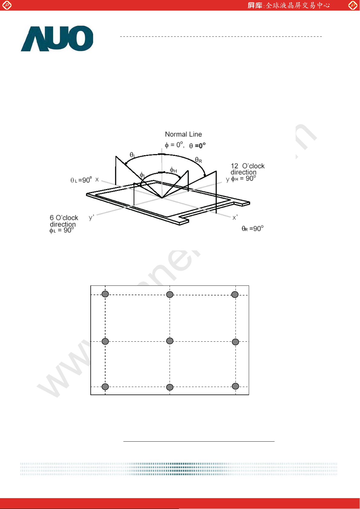
Note 1: Definition of viewing angle
Viewing angle is the measurement of contrast ratio Њ10, at the screen center, over a 180° horizontal and
180° vertical range (off-normal viewing angles). The 180° viewing angle range is broken down as follows;
90° (Ӱ) horizontal left and right and 90° (ӥ) vertical, high (up) and low (down). The measurement
direction is typically perpendicular to the display surface with the screen rotated about its center to
develop the desired
measurement viewing angle.
Note 2: 9 points position
90 %
50 %
10 %
10 %
50 %
90 %
Note 3: The luminance uniformity of 9 points is defined by dividing the maximum luminance values by the
minimum test point luminance
Ӭ
W9
Minimum
=
Maximum
Luminance of 9 points
Luminance of 9 points
d
ocument version 1.0 8/3
One step solution for LCD / PDP / OLED panel application: Datasheet, inventory and accessory!
www.panelook.com
Global LCD Panel Exchange Center
www.panelook.com
Product Specification
AU OPTRONICS CORPORATION
M190EP01 V0
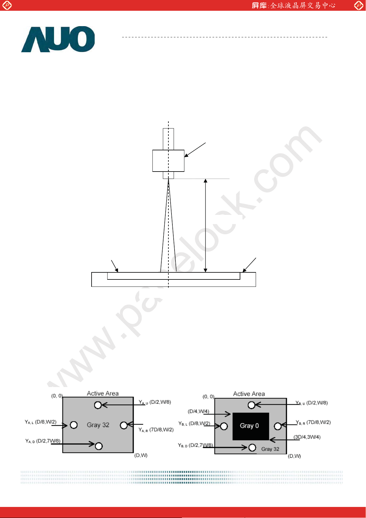
Note 4: Measurement method
The LCD module should be stabilized at given temperature for 30 minutes to avoid abrupt temperature
change during measuring. In order to stabilize the luminance, the measurement should be executed after
lighting Backlight for 30 minutes in a stable, windless and dark room. ʳ
Photo detector
Field=2
50 cm
LCD Panel
Center of the screen
Note 5: Definition of Cross Talk (CT)
CT = | YB – YA | / YA 100 (%)
Where
YA = Luminance of measured location without gray level 0 pattern (cd/m2)
YB = Luminance of measured location with gray level 0 pattern (cd/m2)
TFT-LCD Module
d
ocument version 1.0 9/3
One step solution for LCD / PDP / OLED panel application: Datasheet, inventory and accessory!
www.panelook.com
Global LCD Panel Exchange Center
www.panelook.com
Product Specification
AU OPTRONICS CORPORATION
M190EP01 V0
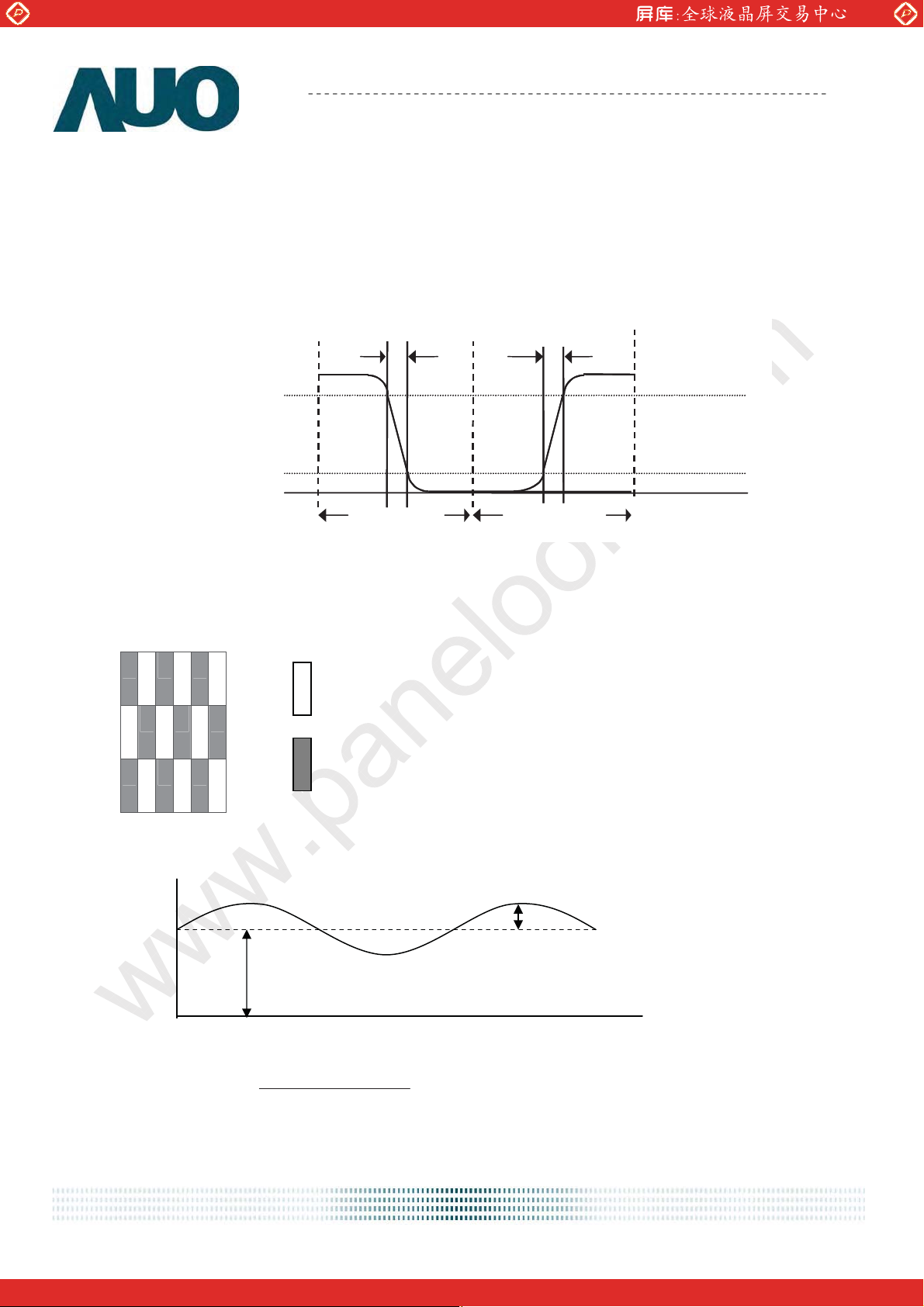
Note 6: Definition of response time
The output signals of photo detector are measured when the input signals are changed from “Full Black” to
“Full White” (rising time), and from “Full White” to “Full Black ”(falling time), respectively. The response time
is interval between the 10% and 90% (1 frame at 60 Hz) of amplitudes. Please refer to the figure as below.
%
ical
ical
Opt
Opt
response
response
100
100
90
10
10
%
Wh
0
0
Tr
Tr
F
F
ite Black
1 Frame 1 Frame
Black
Tr
Tr
R
R
Wh
ite
Note 7: Subchecker Pattern
R G B R G B
Gray Level = L127
R G B R G B
Gray Level = L0
R G B R G B
Method: Record dBV & DC value with (WESTAR)TRD-100
Amplitude
DC
AC
Time
log20(dB)Flicker
Hz) 30Level(at AC
Level DC
d
ocument version 1.0 10/3
One step solution for LCD / PDP / OLED panel application: Datasheet, inventory and accessory!
www.panelook.com
Global LCD Panel Exchange Center
www.panelook.com
Product Specification
M190EP01 V0
AU OPTRONICS CORPORATION
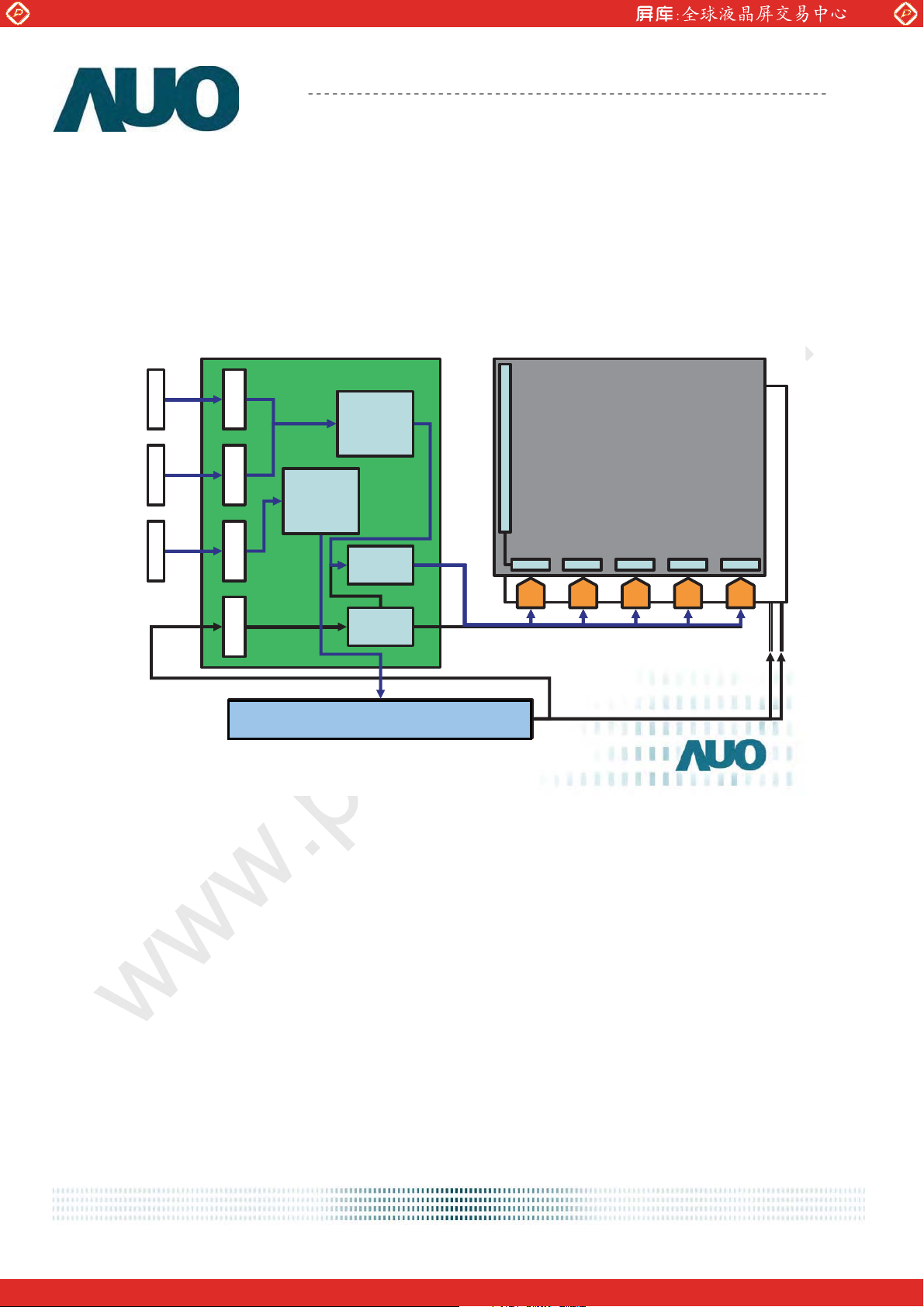
3. Functional Block Diagram
The following diagram shows the functional block of the 19.0 inches Color TFT-LCD Module:
29
-Jun-05
slide
Block Diagram
D-Sub
DVI
Ke
y pad
PCBA
MC
Scaler
U
RS
G
DS
amma
Dr
WO
1280(3) x 1024
iver IC
A
Driver IC
2
Power module (Include inverter)
UO Proprietary & Confidential
A
DC to DC
Lamp connector
Power module
d
ocument version 1.0 11/3
One step solution for LCD / PDP / OLED panel application: Datasheet, inventory and accessory!
www.panelook.com
 Loading...