


 Loading...
USER’S MANUAL
rel. 1.0b

USER’S MANUAL |
AP F8.9 bit |
/ |
|
|
|
Index
1. |
PRODUCT DESCRIPTION / PRECAUTIONS.......................................................................................................................... |
3 |
|||
2. |
PACKAGE CONTENTS............................................................................................................................................................... |
3 |
|||
3. |
AP F8.9 bit and DRC INSTALLATION.................................................................................................................................... |
4 |
|||
4. |
CONNECTION PANEL DESCRIPTION..................................................................................................................................... |
5 |
|||
|
1 |
POWER................................................................................................................................................................................. |
|
5 |
|
|
2 |
CTRL (REM IN-OUT. / CONTROL).................................................................................................................................. |
6 |
||
|
3 |
SPEAKER IN........................................................................................................................................................................ |
|
6 |
|
|
4 |
PRE IN.................................................................................................................................................................................. |
|
7 |
|
|
5 |
SPEAKER OUT..................................................................................................................................................................... |
|
7 |
|
|
6 |
SUB OUT.............................................................................................................................................................................. |
|
8 |
|
|
7 |
OPTICAL IN......................................................................................................................................................................... |
|
8 |
|
|
8 |
DRC |
................................................................................................................................................................................... |
|
8 |
|
9 |
USB |
................................................................................................................................................................................... |
|
8 |
|
10 |
UPGRADE OFF-ON............................................................................................................................................................ |
8 |
||
|
11 |
PRESET................................................................................................................................................................................ |
|
8 |
|
|
12 |
FUSE |
................................................................................................................................................................................... |
|
8 |
|
13 |
LOGO STATUS.................................................................................................................................................................... |
|
9 |
|
5. |
CONNECTIONS.......................................................................................................................................................................... |
|
10 |
||
|
5.1 |
POWER SUPPLY AND REMOTE TURN ON................................................................................................................. |
10 |
||
|
5.2 |
INPUT SIGNALS............................................................................................................................................................... |
11 |
||
|
5.3 |
DIGITAL OPTICAL IN INPUT SIGNALS........................................................................................................................ |
14 |
||
|
5.4 |
OUTPUT SIGNALS........................................................................................................................................................... |
15 |
||
|
|
5.4.1 PRESET |
0 DEFAULT: 3 WAY ACTIVE FRONT + REAR + EXTERNAL SUBWOOFER.................................. |
16 |
|
|
|
5.4.2 |
PRESET |
1: 2 WAY ACTIVE FRONT + 2 PASSIVE REAR + SUBWOOFER.................................................... |
17 |
|
|
5.4.3 |
PRESET |
2: 3 WAY ACTIVE FRONT + SUBWOOFER....................................................................................... |
18 |
|
|
5.4.4 |
PRESET |
3: FRONT + REAR + SUBWOOFER.................................................................................................... |
19 |
|
|
5.4.5 PRESET |
4: 2 WAY ACTIVE FRONT + REAR + SUBWOOFER........................................................................ |
20 |
|
|
|
5.4.6 |
PRESET |
5: 3 WAY ACTIVE FRONT + REAR + EXTERNAL AMPLIFIED SUB.............................................. |
21 |
|
|
5.4.7 |
PRESET |
6: 2 WAY ACTIVE FRONT + REAR + EXTERNAL AMPLIFIED SUB.............................................. |
22 |
|
5.5 |
5.4.8 |
PRESET |
7: 2 WAY ACTIVE FRONT + REAR + 2 WAY CENTER CHANNEL + EXTERNAL AMPLIFIED SUB... |
23 |
|
PERSONAL COMPUTER AND DIGITAL REMOTE CONTROL (DRC)...................................................................... |
24 |
|||
6. |
GUIDE FOR INSTALLING/UNINSTALLING AP F8.9 bit SOFTWARE AND DRIVERS.................................................. |
25 |
|||
|
6.1 |
GUIDED PROCEDURE FOR PC SOFTWARE INSTALLATION.................................................................................. |
25 |
||
|
6.2 |
GUIDED PROCEDURE FOR DRIVER INSTALLATION................................................................................................ |
27 |
||
|
6.3 |
UNINSTALLING AP F8.9 bit SOFTWARE..................................................................................................................... |
28 |
||
7. |
HOW TO SET UP AP F8.9 bit WITH A PC............................................................................................................................ |
29 |
|||
|
7.1 |
OFFLINE MODE................................................................................................................................................................ |
29 |
||
|
7.2 |
TARGET MODE................................................................................................................................................................. |
30 |
||
|
7.3 |
ADJUSTING ACOUSTIC REPRODUCTION.................................................................................................................. |
36 |
||
|
|
7.3.1 |
DEVICE INFO......................................................................................................................................................... |
36 |
|
|
|
7.3.2 |
FILE MAIN MENU................................................................................................................................................. |
37 |
|
|
|
7.3.3 MEMORIES MAIN MENU.................................................................................................................................... |
37 |
||
|
|
7.3.4 |
SETTINGS MAIN MENU...................................................................................................................................... |
38 |
|
|
|
7.3.5 |
DEVICE MAIN MENU........................................................................................................................................... |
41 |
|
|
|
7.3.6 |
HELP MAIN MENU............................................................................................................................................... |
42 |
|
|
|
7.3.7 |
SELECTED INPUT................................................................................................................................................. |
42 |
|
|
|
7.3.8 |
CHANNEL MAP..................................................................................................................................................... |
42 |
|
|
|
7.3.9 |
SELECT CHANNEL............................................................................................................................................... |
43 |
|
|
|
7.3.10FILTER SETTINGS................................................................................................................................................ |
43 |
||
|
|
7.3.11SET DISTANCE AND DELAY............................................................................................................................... |
45 |
||
|
|
7.3.12PARAMETRIC EQUALIZER.................................................................................................................................. |
48 |
||
|
|
7.3.13OUTPUT LEVEL.................................................................................................................................................... |
49 |
||
|
|
7.3.14MEMORY................................................................................................................................................................ |
49 |
||
|
|
7.3.15STATUS BAR......................................................................................................................................................... |
49 |
||
8. |
TROUBLESHOOTING............................................................................................................................................................... |
50 |
|||
|
8.1 |
SYNCHRONIZATION WITH A PC.................................................................................................................................. |
51 |
||
|
8.2 |
BACKGROUND NOISE..................................................................................................................................................... |
52 |
||
|
8.3 |
FIRMWARE UPGRADE.................................................................................................................................................... |
53 |
||
9. |
ACCESSORIES........................................................................................................................................................................... |
|
53 |
||
|
9.1 |
DRC DIGITAL REMOTE CONTROL............................................................................................................................... |
53 |
||
|
|
9.1.1 |
DRC MP.................................................................................................................................................................. |
|
53 |
|
9.2 |
9.1.2 |
DRC AB................................................................................................................................................................... |
|
53 |
|
SPM4 (Stereo Passive Mixer 4 Ch).............................................................................................................................. |
53 |
|||
|
9.3 |
OP 1.5 TOSLINK OPTICAL CABLE 1,5 m / 59.05 in.................................................................................................. |
54 |
||
|
9.4 |
OP 4.5 TOSLINK OPTICAL CABLE 4,5 m / 177.16 in................................................................................................ |
54 |
||
|
9.5 |
STA - F/F SOCKET TOSLINK ADAPTER...................................................................................................................... |
54 |
||
10. CARATTERISTICHE TECNICHE............................................................................................................................................ |
55 |
||||
2
USER’S MANUAL |
AP F8.9 bit / 1/2 |
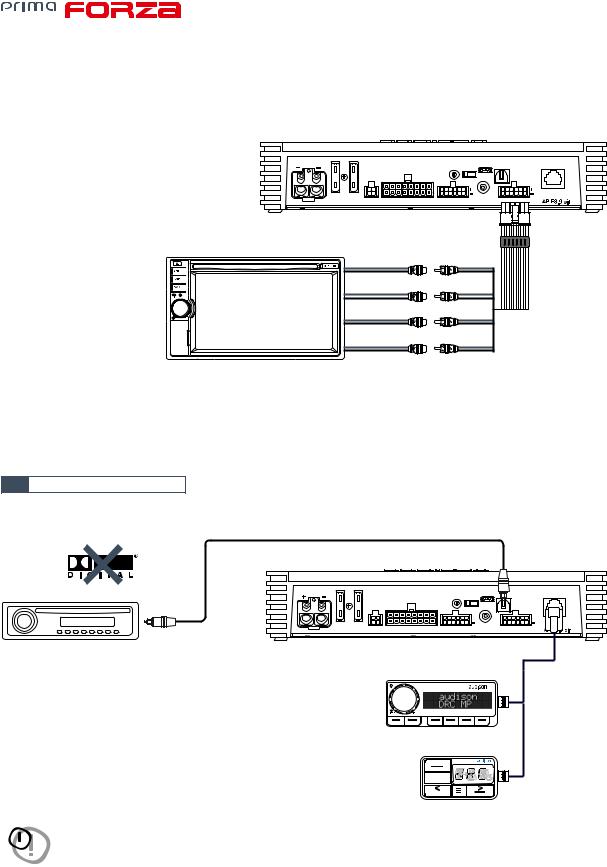
1.PRODUCT DESCRIPTION / PRECAUTIONS
AP F8.9 bit is a 9-channel amplifier with 8 amplified channels settable in bridge mode; it also features a 32 bit, 147 MHz clock speed, 24 bit AD/DA converter digital sound processor (DSP), essential to maximize the acoustic performance of your car audio system.
It can be interfaced with any factory system, even on cars with built-in audio processors, since with the de-equalization function, AP F8.9 bit will send back a linear signal.
It features 13 signal inputs, 6 Hi-Level, 6 Pre-In and 1 S/PDIF optical digital and provides 8 amplified power outputs and 1 pre-amplified that is optimized to drive a subwoofer.
Each output channel provides: graphically adjustable parametric equalization group, 68-frequency steps electronic crossover and BUTTERWORTH or LINKWITZ filters with 6-24 dB slopes and a digital time delay line.
The user can make adjustments that allow him or her to interact with the AP F8.9 bit through the DRC MP remote control device.
WARNING: 1. A PC provided with Windows Vista, Windows 7 or Windows 8 operating system, 1.5 GHz minimum processor speed, 2 GB RAM minimum memory and a 1024 x 600 pixels minimum resolution graphics card as well as at least 1 GB of available hard-disk space are required to install the software and setup the product.
2. Before connecting the product, carefully read this manual. Improper connections may cause damage to AP F8.9 bit or to the speakers in your car audio system.
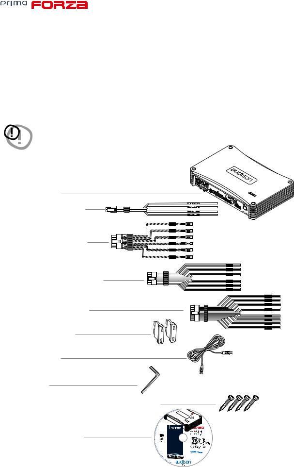
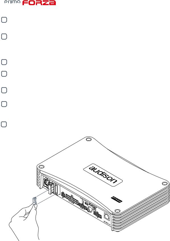
2. PACKAGE CONTENTS
-AP F8.9 bit amplifier
-Multipolar cable, Rem/Control:
|
IN 6 |
|
IN 5 |
- Multipolar cable, Input Pre-IN: |
IN 4 |
IN 3 |
|
|
IN 2 |
|
IN 1 |
- Multipolar cable, Input Speakers IN:
- Multipolar cable Speakers OUT: |
|
|
|
- |
2 - 30 A replacement fuse: |
0 |
A |
|
|
3 |
30 |
|
|
A |
|
- 1.8 m USB cable: |
|
|
|
- 2.5 mm hex key: |
|
|
|
- |
4 - 4.2 x 50 mm self-tapping, cross head mounting screws: |
|
|
- |
CD ROM containing: |
|
|
|
AP F8.9 bit Software |
|
|
|
This owner’s manual (.pdf) |
|
|
|
Audio Test Tracks |
|
|
IN 6
IN 5
IN 4
IN 3
IN 2
IN 1
OUT 8
OUT 7
OUT 6
OUT 5
OUT 4
OUT 3
OUT 2
OUT 1
3

USER’S MANUAL AP F8.9 bit / 3
3. AP F8.9 bit AND DRC INSTALLATION
External size Mounting size
238 mm / 9.37 in.
POWER - 12V |
|
|
PRESETS |
UPGRADE |
USB |
OPTICAL IN |
DRC |
|
|
|
|
||||||
|
|
|
|
0 |
OFF ON |
|
|
|
|
|
|
67 |
12 |
|
|
|
|
|
|
|
5 |
4 |
3 |
|
|
|
FUSE 2x30A |
CTRL |
SPEAKER OUT |
SPEAKER IN |
SUB OUT |
PRE IN |
|
||
|
|
|
|
|
|
6.1 in. |
|
/ 5.3 in. |
|
|
|
|
|
|
|||
|
|
||||
155 mm / |
|
135 mm |
|||
49,5 mm / 1.95 in.
218 mm / 9.4 in.
How to mount
DRC MP (optional)
Light sensor
87 mm / 3.45 in
DRC AB (optional)
SRC
MEM
63 mm / 2.48 in
36 mm / 1.41 in
11 mm / 0.43 in
36 mm / 1.41 in
12 mm / 0.47 in
WARNING for all cable INPUT/OUTPUT
OK |
4
USER’S MANUAL |
AP F8.9 bit / 4 |
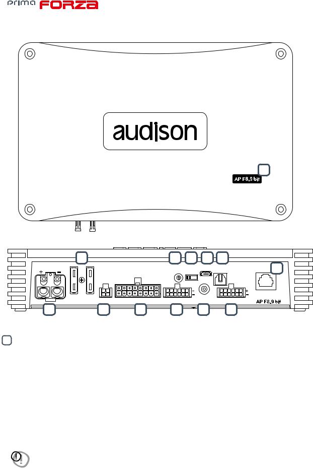
4. CONNECTION PANELS - DESCRIPTION
13
12 |
|
|
11 |
10 |
9 |
7 |
|
|
POWER - 12V |
|
|
PRESETS |
UPGRADE |
USB |
OPTICAL IN |
DRC 8 |
|
|
|
|
||||||
|
|
|
|
0 |
OFF ON |
|
|
|
|
|
|
7 |
1 |
|
|
|
|
|
|
|
6 |
|
2 |
|
|
|
|
|
|
5 |
4 |
3 |
|
|
|
FUSE 2x30A |
CTRL |
SPEAKER OUT |
SPEAKER IN |
SUB OUT |
PRE IN |
|
||
1 |
2 |
5 |
3 |
|
6 |
4 |
|
|
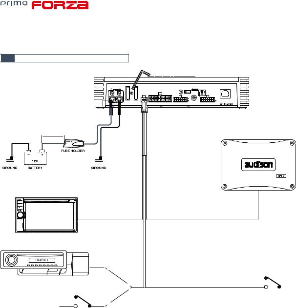
1POWER.
+ Power (11-15 VDC): connection terminal for AP F8.9 bit power supply positive pole. The jack accepts a stripped cable up to 15mm/0.6” with maximum section of 8 AWG ( 3,2mm / 0.12”). For better power transfer we recommend using cables with the largest possible cross-section and with the same cross-section as the cable connected to the negative pole.
- Power (Ground): connection terminal for the negative power supply pole of the amplifier. Connect here the negative battery cable or a cable connected to the vehicle chassis. The soket will take a stripped cable up to 15mm/0.6” with a maximum section of 8 AWG ( 3,2mm / 0.12”). For better power transfer, we recommend using cables with the largest possible section and with the same section as the cable connected to the positive pole.
In order to correctly connect the ground (-), use a screw that is already present on the metal part of the vehicle; If necessary, remove any paint residue or grease, using a tester to make sure there is continuity between the negative terminal (-) on the battery and the mounting point. If possible, connect all of the grounds on the audio components to the same grounding point. This helps reduce most of the interference than can occur in audio reproduction.
WARNING: make sure the connection polarity is as indicated on the terminals. A misconnection may result in damage to the AP F8.9 bit. After applying power, wait at least 10 seconds before turning the AP F8.9 bit on.
5
USER’S MANUAL |
AP F8.9 bit / 4 |
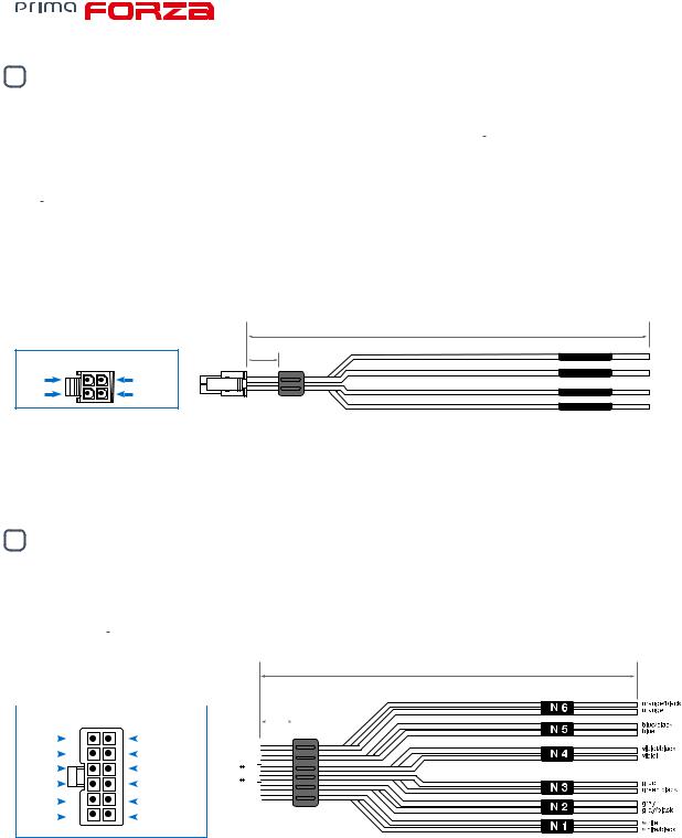
2CTRL (REM IN-OUT / CONTROLS): terminals to turn on and control the AP F8.9bit.
-Remote IN. Input to turn on AP F8.9 bit remotely through the audio signal source Remote Out. REM IN can be connected to the ignition switch terminal (ACC). The voltage must be between 7 and 14.5 VDC. If using a source with amplified outputs such as BTL, AP F8.9bit can be automatically turned on (see sec. 7.2.5 - 7.3.4.7), so it will not be necessary to connect the REM IN terminal.
-Remote OUT. Output to turn on other devices/amplifiers connected after the AP F8.9 bit. From the time it is turned on, it takes 1 second to supply the signal to the REM OUT output, but it will be possible to set this delay via software
(see sec. 7.3.4.7)
The 200 mA output current capability can also drive an automotive relay.
-OPTICAL SEL: it allows the OPTICAL input selection. This control is active bringing the terminal to +12V.
-MASTER EN: it enables the MASTER input selection. This control is active bringing the terminal to +12V. The control signals are interfaced with the AP F8.9 bit via a wiring featuring a 4 pole multipolar connector, described below.
|
|
320 mm / 12.6 in. |
|
|
FRONT VIEW |
10 mm |
OPTICAL SEL. |
pink |
|
|
0.39 in. |
MASTER EN. |
brown |
|
blue |
blue/black |
|||
|
|
|||
brown |
pink |
REM IN |
blue |
|
|
|
REM OUT |
blue/black |
Wire Size: AWG 20
3SPEAKER IN.
AP F8.9 bit is provided with a 12 poles multipolar connector to manage the input signals. Connect up to a maximum of 6 input channels using the multipolar connector supplied.
By default AP F8.9 bit accepts signals coming from Front Left/ Front Right, Rear Left/ Rear Right, and the signal to be applied must have a value ranging between 2.2 and 22 V RMS. Such input channels can be then customized using the PC (see sec. 7.3.4.7).
320 mm / 12.6 in.
|
|
FRONT VIEW |
|
|
|
|
|
|
|
|
|
|
10 mm |
|
|
|
||||
|
|
|
|
|
|
|
|
|
|
|
|
|||||||||
|
|
|
|
|
|
|
|
|
|
|
|
|
|
|||||||
|
|
|
|
|
|
|
|
|
|
|
|
|
|
|
|
0.39 in. |
|
|
|
|
|
|
|
|
|
|
|
|
|
|
|
|
|
|
|
|
|||||
orange |
|
|
|
|
|
orange/black |
|
|
|
|||||||||||
|
|
|
|
|
|
|||||||||||||||
|
|
|
|
|
|
|
||||||||||||||
blue |
|
|
|
|
|
blue/black |
|
|
|
|
|
|
|
|
||||||
|
|
|
|
|
|
|
|
|
|
|
|
|
|
|
|
|
|
|||
|
|
|
|
|
|
|
|
|
|
|
|
|
||||||||
purple |
|
|
|
|
|
purple/black |
|
|
|
|
|
|
|
|
|
|
|
|
|
|
|
|
|
|
|
|
|
|
|
|
|
|
|
|
|
|
|
|
|||
green |
|
|
|
|
|
green/black |
|
|
|
|
|
|
|
|
|
|
|
|
|
|
gray |
|
|
|
|
|
gray/black |
|
|
|
|
|
|
|
|
|
|
|
|
|
|
|
|
|
|
|
|
|
|
|
|
|
|
|
||||||||
|
|
|
|
|
|
|
|
|
|
|
|
|
||||||||
white |
|
|
|
|
|
white/black |
|
|||||||||||||
|
|
|
|
|
|
|||||||||||||||
|
|
|
||||||||||||||||||
|
|
|
|
|
|
|
|
|
|
|
|
|
|
|
|
|
|
|
|
|
Wire Size: AWG 20
The channels FL FR RL RR feature the AUTO TURN ON (ART) function, automatic turn on/off, when connected with the source loudspeakers outputs. This function can be disabled via PC Software.
6
USER’S MANUAL |
AP F8.9 bit / 4 |
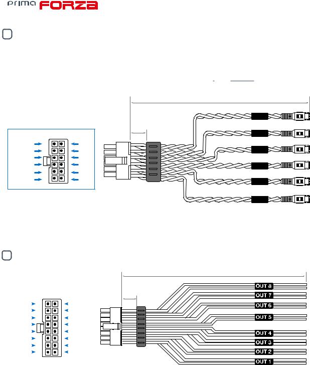
4PRE IN
AP F8.9 bit is provided with a 12 pole multipolar connector to manage the PRE IN input signals, by soldering the RCA female connectors to the terminals, or using the accessory ACP6 to interface head units featuring a PRE OUT output. Connect up to a maximum of 6 input channels using the multipolar connector supplied or the extra cable provided with RCA connectors. By default the AP F8.9 bit accepts signals coming from Front Left/ Front Right, Rear Left/ Rear Right, Center/ Sub and the signal to be applied must have a value ranging between 0.6 and 6 V RMS (Fig.4). Such input channels can be then customized using the PC (see sec. 5.2 - 7.3.5).
|
|
320 mm / 12.6 in. |
|
|
IN 6 |
FRONT VIEW |
10 mm |
IN 5 |
0.39 in. |
||
orange/black |
orange |
IN 4 |
blue/black |
blue |
|
purple/black |
purple |
|
green/black |
green |
IN 3 |
gray/black |
gray |
|
white/black |
white |
IN 2 |
|
|
IN 1
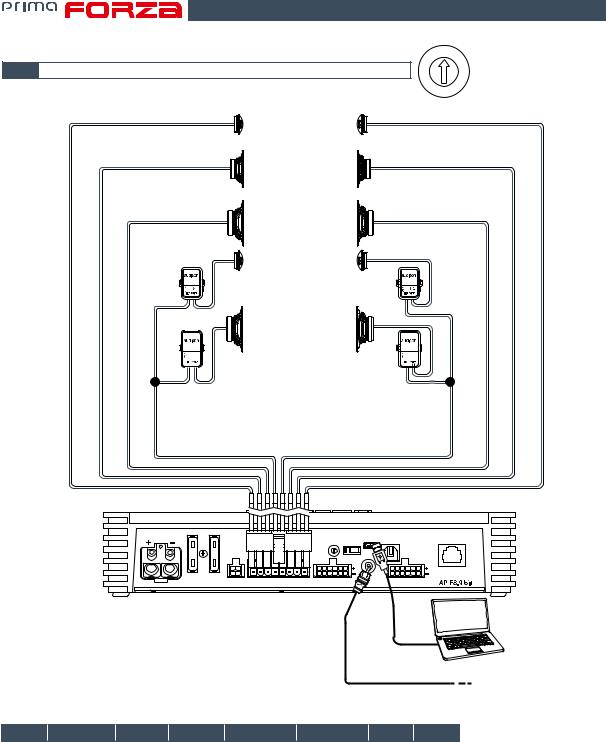
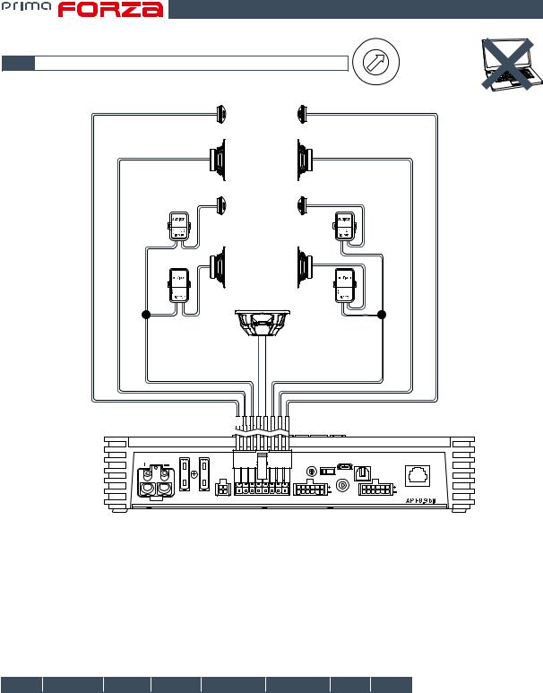
5SPEAKER OUT.
AP F8.9 bit is provided with a 16 pole multipolar connector to manage the power output signals.
|
|
FRONT VIEW |
||
OUT 8 - |
|
|
|
OUT 8 + |
|
|
|||
OUT 7 - |
|
|
|
OUT 7 + |
|
|
|
||
OUT 6 - |
|
|
|
OUT 6 + |
|
|
|||
OUT 5 - |
|
|
|
OUT 5 + |
|
|
|
||
OUT 4 - |
|
|
|
OUT 4 + |
|
|
|||
OUT 3 - |
|
|
|
OUT 3 + |
|
|
|
||
OUT 2 - |
|
|
|
OUT 2 + |
|
|
|||
OUT 1 - |
|
|
|
OUT 1 + |
|
|
|
||
|
|
|
|
|
320 mm / 12.6 in.
10 mm
0.39 in.
Wire Size: AWG 16
+
-
+
-
+
-
+
-
+
-
+
-
+
-
+
-
A minimum of 4 and a maximum of 8 speakers can be configured based on the system you wish to create in your vehicle.
7
USER’S MANUAL |
AP F8.9 bit / 4 |
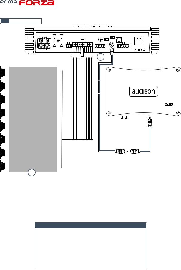
6SUB OUT.
Pre-amplified output subject to LO PASS filtering optimized to drive a mono amplifier for an external subwoofer or active subwoofer. (see sec. 5.4)
7OPTICAL IN.
AP F8.9 bit accepts at its input PCM signals up to 192 kHz / 24 bit sampling frequency rate. So DOLBY DIGITAL (AC3) multi-channel signals coming from audio/video sources (such as the audio of a film in DVD) or DTS can not be reproduced. Connect a fiber optic cable with a TOSLINK connector. This input can be selected using the external DRC control or by activating it using the OPTICAL IN terminal. (see sec. 5.3)
8DRC.
Connection terminal for remote control of the functions (OPTIONAL) of the AP F8.9 bit (see sec. 5.5)
9USB.
USB (micro) connection to connect the product to a PC in order to manage the functions using AP F8.9 bit software. The connection is USB 1.1/2.0/3.0 compatible.
10UPGRADE OFF-ON.
Switch ON allows the product to be updated in BOOT LOADER mode. (see sec. 8.3)
11PRESET.
AP F8.9 bit features 8 setups preloaded in its memory, one being editable. They allow the product to be used without the need to connect it to a PC. (see sec. 5.4.1; 5.4.8). The preset choice is based on the factory system in the car or the type of system you wish to create.
12FUSE.
30 A blade protection fuse. In case the fuse needs to be replaced, use same type and value as the original.
2 X 30A
Blade fuse
8

USER’S MANUAL |
AP F8.9 bit / 4 |
13LOGO STATUS.
AP F8.9 bit is provided with a built-in control that manages its status and protects the circuits and connections to the speakers. The logo on the AP F8.9 bit top cover will change its status in case of any possible product malfunctions.
A BLUE logo means: AP F8.9 bit is on.
Flashing RED/BLUE logo means:
The “UPGRADE MODE” switch on the product is set to “ON” position, or the product Firmware is being updated.
Flashing BLUE logo means:
The unit is in stand-by (energy saver) because there is no audio signal. This function (AST) can be activated using the PC software. (see sec. 7.3.4.7) and the stand-by time ranges from a minimum of 5 mins. to a maximum of 20 mins. The unit will automatically turn off after 30 mins. when there is no signal.
Flashing RED logo means:
-AP F8.9 bit temperature reached 75° C and the thermal protection was triggered. It will start operating again at around 70° C.
RED logo flashing twice every second means:
-Output overload. The red LED flashes when the output load goes below the minimum allowed capacity of about
2Ω impedance. The LED comes on without flashing, activating the protection. When listening to music, if the acoustic reproduction stops for a few seconds, check if the red amplifier LED is flashing. This means there was an overload. Turn the amplifier off and check the speakers and wirings. This protection is self-restoring.
-Speaker wiring anomaly. The red LED flashes when a terminal on the speaker goes in short-circuit with the vehicle chassis. When listening to music, if the acoustic reproduction stops for a few seconds, check to see if the red amplifier LED is flashing; this means there was a short circuit between a terminal on a speaker and
the vehicle chassis. Turn off the amplifier and check the speakers and wiring. This protection is self-restoring.
RED logo flashing four times every second means:
-The “OVER VOLTAGE” protection activation, due to the fact that the battery voltage is higher than 16V. The product will turn off after 3 minutes.
WARNING: check the state of charge of the car alternator.
RED logo means:
- Product internal fault. Please contact an authorized service centre. The product will turn off after 3 minutes.
9
USER’S MANUAL |
AP F8.9 bit / 5 |
5.CONNECTIONS
5.1POWER SUPPLY AND REMOTE TURN ON
HEX KEY 2,5 mm
POWER - 12V
15 mm/ 0.6 in. |
FUSE 2x30A |
|
8 AWG Max |
||
|
Max 20 cm / 7.9 in.
(Not provided. Suggested Fuse 30 A delayed)
HEAD UNIT |
blue REM IN |
REMOTE OUT |
SD
|
REMOTE OUT |
OPTICAL/SEL |
|
|
|
OPTICAL SOURCE |
|
pink |
|
|
|
TO ACTIVE + 12 V |
|
|
OPTICAL INPUT |
|
|
|
PRESETS |
UPGRADE |
USB |
OPTICAL IN |
DRC |
|
|
|
0 |
OFF ON |
|
|
|
|
67 |
12 |
|
|
|
|
|
5 4 |
3 |
|
|
|
|
SPEAKER OUT |
SPEAKER IN |
SUB OUT |
PRE IN |
|
||
EXTERNAL SUBWOOFER
AMPLIFIER (Optional)
REM IN
blue/white REM OUT
brown MASTER ENABLE |
+ 12 V |
* (see sec. 7.3.4.7)
Turn AP F8.9 bit on and off
AP F8.9 bit is on when the logo is blue. It can be turned on/off using the following methods:
1.By pressing on the main DRC control knob (ON). By holding down the main control knob on the DRC (OFF). In this case, no other Remote In connections are needed, but they can co-exist.
2.By connecting the REMOTE IN terminal with a Remote Out signal coming from an after market audio source.
3.Through the Hi Level MASTER (FL - FR) input. The AUTO TURN ON (ART) function is activated by connecting the output of an amplified source to the INPUT FL - FR input channel. This function can be enabled/disabled using
AP F8.9 bit PC software (see sec. 7.3.4.7).
4.Using the Speaker IN input. The AUTO TURN ON (AST) function is activated by connected the outputs
on a amplified source to the input channels to the AP F8.9 bit input channels.
This function can be enabled/disabled using AP F8.9 bit PC Software. This turn on control is available on the IN 1; IN 2; IN 3; IN 4; IN5; IN6 inputs (see sec. 7.3.4.7).
10
USER’S MANUAL |
AP F8.9 bit / 5 |
5.2INPUT SIGNALS
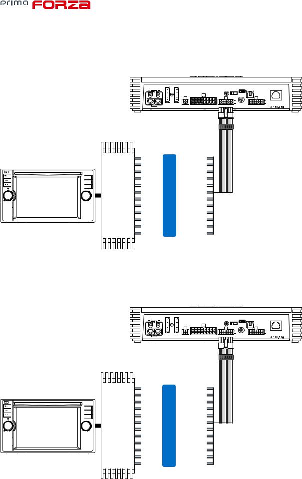
1.SPEAKER INPUT: FRONT + REAR
POWER - 12V |
|
PRESETS |
UPGRADE USB |
OPTICAL IN |
DRC |
|
|
|
|||||
|
|
|
0 |
OFF ON |
|
|
|
|
67 |
12 |
|
|
|
|
|
5 4 |
3 |
|
|
|
FUSE 2x30A |
CTRL |
SPEAKER OUT |
|
SUB OUT |
PRE IN |
|
OEM SOURCE
FL+ |
IN 1+ |
white |
FL- |
IN 1- |
white/black |
FR+ |
IN 2+ |
gray |
FR- |
IN 2- |
gray/black |
RL+ |
IN 3+ |
green |
RL- |
IN 3- |
green/black |
RR+ |
IN 4+ |
violet |
RR- |
IN 4- |
violet/black |
(see sec. 7.2.5.1)
2. SPEAKER INPUT: 2 WAY FRONT + REAR
POWER - 12V |
|
|
PRESETS |
UPGRADE |
USB |
OPTICAL IN |
DRC |
|
|
|
|
||||||
|
|
|
|
0 |
OFF ON |
|
|
|
|
|
|
67 |
12 |
|
|
|
|
|
|
|
5 4 |
3 |
|
|
|
|
FUSE 2x30A |
CTRL |
SPEAKER OUT |
SPEAKER IN |
SUB OUT |
PRE IN |
|
||
OEM SOURCE
OEM AMPIFIER
(see sec. 7.2.5.6)
FL TW+ |
IN 1+ |
white |
FL TW- |
IN 1- |
white/black |
FR TW+ |
IN 2+ |
gray |
FR TW- |
IN 2- |
gray/black |
FL WF+ |
IN 3+ |
green |
FL WF- |
IN 3- |
green/black |
FR WF + |
IN 4+ |
violet |
FR WF- |
IN 4- |
violet/black |
RL+ |
IN 5+ |
cyan |
RL- |
IN 5- |
cyan/black |
RR+ |
IN 6+ |
orange |
RR- |
IN 6- |
orange/black |
|
|
|
11
USER’S MANUAL |
AP F8.9 bit / 5 |
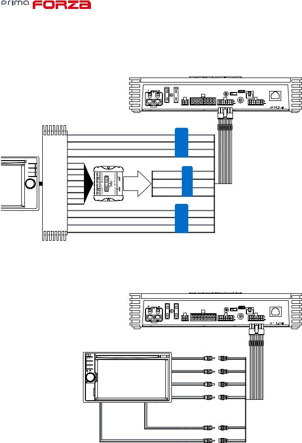
3. SPEAKER INPUT: FRONT + REAR + CENTER + SUB
POWER - 12V |
|
|
PRESETS |
UPGRADE |
USB |
OPTICAL IN |
DRC |
|
|
|
|
||||||
|
|
|
|
0 |
OFF ON |
|
|
|
|
|
|
67 |
12 |
|
|
|
|
|
|
|
5 4 |
3 |
|
|
|
|
FUSE 2x30A |
CTRL |
SPEAKER OUT |
SPEAKER IN |
SUB OUT |
PRE IN |
|
||
OEM SOURCE
OEM AMPIFIER
(see sec. 7.2.5.4)
FL + |
IN 1+ |
white |
FL - |
IN 1- |
white/black |
FR + |
IN 2+ |
gray |
FR - |
IN 2- |
gray/black |
RL + |
IN 3+ |
green |
RL - |
IN 3- |
green/black |
RR + |
IN 4+ |
violet |
RR - |
IN 4- |
violet/black |
CENTER + |
IN 5+ |
cyan |
CENTER - |
IN 5- |
cyan/black |
SUB + |
IN 6+ |
orange |
SUB - |
IN 6- |
orange/black |
|
|
|
4. SPEAKER INPUT: FRONT + REAR + LEFT SUB + RIGHT SUB
POWER - 12V |
|
|
PRESETS |
UPGRADE |
USB |
OPTICAL IN |
DRC |
|
|
|
|
||||||
|
|
|
|
0 |
OFF ON |
|
|
|
|
|
|
67 |
12 |
|
|
|
|
|
|
|
5 4 |
3 |
|
|
|
|
FUSE 2x30A |
CTRL |
SPEAKER OUT |
SPEAKER IN |
SUB OUT |
PRE IN |
|
||
OEM SOURCE
OEM AMPIFIER
(see sec. 7.2.5.3)
FL + |
IN 1+ |
white |
FL - |
IN 1- |
white/black |
FR + |
IN 2+ |
gray |
FR - |
IN 2- |
gray/black |
RL + |
IN 3+ |
green |
RL - |
IN 3- |
green/black |
RR + |
IN 4+ |
violet |
RR - |
IN 4- |
violet/black |
SUB L+ |
IN 5+ |
cyan |
SUB L- |
IN 5- |
cyan/black |
SUB R+ |
IN 6+ |
orange |
SUB R- |
IN 6- |
orange/black |
|
|
|
12
USER’S MANUAL |
AP F8.9 bit / 5 |
5. SPEAKER INPUT: 3 WAY FRONT + REAR
|
|
|
POWER - 12V |
|
|
|
PRESETS |
UPGRADE |
USB |
OPTICAL IN |
DRC |
|
|
|
|
|
|
|
|
||||||
|
|
|
|
|
|
|
|
0 |
OFF ON |
|
|
|
|
|
|
|
|
|
|
67 |
12 |
|
|
|
|
|
|
|
|
|
|
|
5 4 3 |
|
|
|
||
|
|
|
FUSE 2x30A |
CTRL |
|
SPEAKER OUT |
SPEAKER IN |
SUB OUT |
PRE IN |
|
||
|
FL TW+ |
|
IN 1+ |
|
white |
|
|
|
|
|
|
|
|
FL TW- |
|
IN 1- |
|
white/black |
|
|
|
|
|
|
|
|
FR TW+ |
|
IN 2+ |
|
gray |
|
|
|
|
|
|
|
OEM SOURCE |
FR TW- |
|
IN 2- |
|
gray/black |
|
|
|
|
|
|
|
|
FL MID+ |
|
|
|
|
|
|
|
|
|
|
|
AMPIFIER |
FL MID- |
MID + WF |
WF+MID RIGHT+ IN 4+ |
violet |
|
|
|
|
|
|
||
FL WF+ |
|
|
|
|
|
|
||||||
|
FR MID+ |
|
WF+MID LEFT+ |
IN 3+ |
green |
|
|
|
|
|
|
|
|
FR MID- |
FRONT MIX |
WF+MID LEFT- |
IN 3- green/black |
|
|
|
|
|
|
||
|
|
|
|
|
|
|
|
|
|
|
|
|
OEM |
FL WF- |
|
WF+MID RIGHTIN 4- |
violet/black |
|
|
|
|
|
|
||
FR WF+ |
|
|
|
|
|
|
|
|||||
|
|
|
|
|
|
|
|
|
|
|
||
|
|
|
|
|
|
|
|
|
|
|
|
|
|
FR WF- |
|
|
|
|
|
|
|
|
|
|
|
|
RL+ |
|
IN 5+ |
|
cyan |
|
|
|
|
|
|
|
|
RL- |
|
IN 5- |
|
cyan/black |
|
|
|
|
|
|
|
|
RR+ |
|
IN 6+ |
|
orange |
|
|
|
|
|
|
|
|
RR- |
|
IN 6- |
orange/black |
|
|
|
|
|
|
||
6. PRE INPUT FRONT + REAR + CENTER + SUB + REAR
POWER - 12V |
|
|
PRESETS |
UPGRADE |
USB |
OPTICAL IN |
DRC |
|
|
|
|
||||||
|
|
|
|
0 |
OFF ON |
|
|
|
|
|
|
67 |
12 |
|
|
|
|
|
|
|
5 4 |
3 |
|
|
|
|
FUSE 2x30A |
CTRL |
SPEAKER OUT |
SPEAKER IN |
SUB OUT |
PRE IN |
|
||
(see sec. 7.2.5.3) |
|
FRONT LEFT |
IN 1 |
FRONT RIGHT |
IN 2 |
REAR LEFT |
IN 3 |
SD |
|
REAR RIGHT |
IN 4 |
CENTER OUT |
IN 5 |
SUB OUT |
IN 6 |
13
USER’S MANUAL |
AP F8.9 bit / 5 |
7. PRE INPUT FRONT + REAR + CENTER + SUB + REAR
POWER - 12V |
|
|
PRESETS |
UPGRADE |
USB |
OPTICAL IN |
DRC |
|
|
|
|
||||||
|
|
|
|
0 |
OFF ON |
|
|
|
|
|
|
67 |
12 |
|
|
|
|
|
|
|
5 4 |
3 |
|
|
|
|
FUSE 2x30A |
CTRL |
SPEAKER OUT |
SPEAKER IN |
SUB OUT |
PRE IN |
|
||
FRONT LEFT
FRONT RIGHT
REAR LEFT
IN 1
IN 2
IN 3
SD
REAR RIGHT |
IN 4 |
(see sec. 7.2.5.1)
5.3 DIGITAL OPTICAL IN INPUT
OPTICAL FIBER (vedi sez. 9.4; 9.5)
TOSLINK connector
POWER - 12V |
|
|
PRESETS |
UPGRADE |
USB |
IN |
DRC |
|
|
|
|
||||||
|
|
|
|
0 |
OFF ON |
|
|
|
|
|
|
67 |
12 |
|
|
|
|
|
|
|
5 |
4 |
3 |
|
|
|
FUSE 2x30A |
CTRL |
SPEAKER OUT |
SPEAKER IN |
SUB OUT |
PRE IN |
|
||
PCM Stereo signal, max 192 kHz / 24 bit
DRC MP (Optional)
DRC AB (Optional)
SRC
MEM
WARNING: the digital input accepts up to 192 kHz / 24 bit stereo PCM signals. So DOLBY DIGITAL (AC3) multi-channel signals coming from audio/video sources (such as the audio of a film in DVD) or DTS can not be reproduced. The output of  these devices will therefore have to be set in STEREO mode for the signal to be reproduced.
How to select the OPTICAL input:
1.Using the DRC, selecting the OPTICAL input.
2.Using the OPTICAL IN terminal.
This command is active connecting the terminal to + 12V.
14
USER’S MANUAL |
AP F8.9 bit / 5 |
5.4 OUTPUT SIGNALS
POWER - 12V |
|
PRESETS |
UPGRADE |
USB |
OPTICAL IN |
DRC |
|
|
|
||||||
|
|
|
0 |
OFF ON |
|
|
|
|
|
7 |
1 |
|
|
|
|
|
|
6 |
|
2 |
|
|
|
|
|
5 4 |
3 |
|
|
|
|
FUSE 2x30A |
CTRL |
SPEAKER IN |
T |
PRE IN |
|
||
2
16: White |
OUT 1+ |
|
|
|
|
8: White/Black |
OUT 1- |
|
15: White |
OUT 2+ |
|
|
|
|
7: White/Black |
OUT 2- |
|
14: White |
OUT 3+ |
|
|
|
|
6: White/Black |
OUT 3- |
|
13: White |
OUT 4+ |
|
5: White/Black |
OUT 4- |
|
12: White |
OUT 5+ |
|
4: White/Black |
OUT 5- |
|
11: White |
OUT 6+ |
|
3: White/Black |
OUT 6- |
|
10: White |
OUT 7+ |
|
2: White/Black |
OUT 7- |
|
9: White |
OUT 8+ |
|
1: White/Black |
OUT 8- |
|
1
1.AP F8.9 bit provides 8 amplified outputs. Through the PC Software, each output channel is provided with the following (ee sec. 7.2):
-a 10 pole graphic equalizer;
-a 68-frequency electronic crossover and Butterworth or Linkwitz-Riley type filters with 6-24 dB slopes (see sec. 7.3.10);
-a digital time delay line (see sec. 7.3.11);
-phase inversion activation (see sec. 7.3.10.2);
-adjustment of the output level to better align the total system response (see sec. 7.3.13);
CH 1÷CH 8 AMPLIFIED OUTPUT CHANNELS CONFIGURATION
POWER CHANNEL CONFIG
|
STEREO MODE |
BRIDGE MODE |
|
CH1 85 W @ 4 Ohm / 150 W @ 2 Ohm |
CH1+ / CH2 - 300 W @ 4 Ohm |
||
CH2 |
85 W @ 4 Ohm / 150 W @ 2 Ohm |
||
|
|||
|
|
||
CH3 85 W @ 4 Ohm / 150 W @ 2 Ohm |
CH3+ / CH4 - 300 W @ 4 Ohm |
||
CH4 |
85 W @ 4 Ohm / 150 W @ 2 Ohm |
||
|
|||
CH5 85 W @ 4 Ohm / 150 W @ 2 Ohm |
CH5+ / CH6 - 300 W @ 4 Ohm |
||
CH6 |
85 W @ 4 Ohm / 150 W @ 2 Ohm |
||
|
|||
|
|
||
CH7 85 W @ 4 Ohm / 150 W @ 2 Ohm |
CH7+ / CH8 - 300 W @ 4 Ohm |
||
CH8 |
85 W @ 4 Ohm / 150 W @ 2 Ohm |
||
|
|||
2.AP F8.9 bit features a preamplified output (4 V Rms max.) SUB OUT that exclusively controls a mono amplifier for subwoofer, or one active subwoofer to amplify the sound system. This output can be activated during I/O Wizard Configuration (see sec. 7.2.9).
15
USER’S MANUAL |
|
|
AP F8.9 bit / 5 |
|
7 |
0 |
1 |
5.4.1 PRESET 0 DEFAULT: 3 WAY ACTIVE FRONT + REAR + EXTERNAL SUBWOOFER 6 |
|
2 |
|
|
5 |
4 |
3 |
TW |
TW |
|
|
LEFT |
RIGHT |
|
|
FRONT |
FRONT |
|
|
MD |
MD |
|
|
LEFT |
RIGHT |
|
|
FRONT |
FRONT |
|
|
WF |
WF |
|
|
LEFT |
RIGHT |
|
|
FRONT |
FRONT |
|
|
REAR |
REAR |
|
|
LEFT |
RIGHT |
|
|
|
|
|
|
|
|
|
|
|
|
|
|
|
|
|
|
|
|
|
|
|
|
|
|
|
|
|
|
|
|
|
|
|
|
|
|
|
|
|
|
|
|
|
|
|
|
|
|
|
|
|
|
|
|
|
|
|
|
|
|
|
|
|
|
|
|
|
|
|
|
|
|
|
|
|
|
|
|
|
|
|
|
|
|
|
|
|
|
|
|
|
|
|
|
|
|
|
|
|
|
|
|
|
|
|
|
|
|
|
|
|
|
|
|
(+) |
(-) |
(+) |
(-) |
(+) |
(-) |
(+) |
(-) |
(+) |
(-) |
(+) |
(-) |
(+) |
(-) |
(+) |
(-) |
||||||||||||||||||||||
Out 1 |
Out 1 |
Out 3 |
Out 3 |
Out 5 |
Out 5 |
Out 7 |
Out 7 |
|
|
|
|
|
|
|
|
|
|
|
|
|
|
|
|
|
|
|
|
|
|
Out 8 |
Out 8 |
Out 6 |
Out 6 |
Out 4 |
Out 4 |
Out 2 |
Out 2 |
|
|
|
|
|
|
|
|
|
|
|
|
|
|
|
|
|
|
|
|
|
|
|
|
|
|
|
|
|
|
|
|
|
|
|
|
|
|
|
|
|
|
|
|
|
|
|
|
|
|
|
|
|
|
|
|
|
|
|
|
|
|
|
|
|
|
|
|
|
|
|
|
|
|
|
|
POWER - 12V |
USB OPTICAL IN |
DRC |
PRESETS UPGRADE |
|
0 |
OFF |
ON |
7 |
1 |
|
|
6 |
|
2 |
|
5 |
4 3 |
|
|
FUSE 2x30A |
CTRL |
SPEAKER OUT |
SPEAKER IN |
OUT |
PRE IN |
INPUT CONFIGURATION:
Master input: Front + Rear
Optical: S/P-DIF PCM 192kHz/24 bit max
OUTPUT CONFIGURATION:
to SUBWOOFER amplifier
|
OUTPUT |
TYPE |
CUT FILTER |
FILTER TYPE |
CUT FREQUENCY |
TIME ALIGNMENT* |
POWER 4Ω |
POWER 2Ω |
|
|
|
||||||||
|
OUT 1 |
FRONT TW LEFT |
HI PASS |
Linkwitz |
5000 Hz @12 dB |
0 |
85 W |
150 W |
|
|
|
|
|
|
|
|
|
|
|
|
OUT 2 |
FRONT TW RIGHT |
HI PASS |
Linkwitz |
5000 Hz @12 dB |
0 |
85 W |
150 W |
|
|
|
|
|
|
|
|
|
|
|
|
OUT 3 |
FRONT MD LEFT |
BAND PASS |
Linkwitz |
500 Hz @12 dB |
0 |
85 W |
150 W |
|
|
3000 HZ @ 12 dB |
|
|||||||
|
|
|
|
|
|
|
|
|
|
|
|
|
|
|
|
|
|
|
|
|
OUT 4 |
FRONT MD RIGHT |
BAND PASS |
Linkwitz |
500 Hz @12 dB |
0 |
85 W |
150 W |
|
|
3000 HZ @ 12 dB |
|
|||||||
|
|
|
|
|
|
|
|
|
|
|
|
|
|
|
|
|
|
|
|
|
OUT 5 |
FRONT WF LEFT |
BAND PASS |
Linkwitz |
80 Hz @12 dB |
0 |
85 W |
150 W |
|
|
500 HZ @ 12 dB |
|
|||||||
|
|
|
|
|
|
|
|
|
|
|
OUT 6 |
FRONT WF RIGHT |
BAND PASS |
Linkwitz |
80 Hz @12 dB |
0 |
85 W |
150 W |
|
|
500 HZ @ 12 dB |
|
|||||||
|
|
|
|
|
|
|
|
|
|
|
|
|
|
|
|
|
|
|
|
|
OUT 7 |
REAR LEFT FULL |
HI PASS |
Linkwitz |
80 Hz @12 dB |
0 |
85 W |
150 W |
|
|
|
|
|
|
|
|
|
|
|
|
OUT 8 |
REAR RIGHT FULL |
HI PASS |
Linkwitz |
80 Hz @12 dB |
0 |
85 W |
150 W |
|
|
|
|
|
|
|
|
|
|
|
|
SUB OUT |
SUB WOOFER |
LO PASS |
Linkwitz |
80 Hz @12 dB |
0 |
- |
- |
|
|
|
|
|
|
|
|
|
|
|
16
USER’S MANUAL |
|
|
AP F8.9 bit / 5 |
|
7 |
0 |
1 |
5.4.2 PRESET 1: 2 WAY ACTIVE FRONT + 2 WAY PASSIVE REAR + SUBWOOFER 6 |
|
2 |
|
|
5 |
4 |
3 |
TW |
TW |
|
|
LEFT |
RIGHT |
|
|
FRONT |
FRONT |
|
|
WF |
WF |
|
|
LEFT |
RIGHT |
|
|
FRONT |
FRONT |
|
|
|
|
|
REAR |
|
|
REAR |
|
|
|
|
|
|
|
LEFT |
|
|
RIGHT |
|
|
|
|
|
|
|
|
SUBWOOFER |
|
|
|
|
|
|
(+) |
(-) |
(+) (-) |
(+) (-) |
(+) |
(-) |
(+) |
(-) |
(+) |
(-) |
(+) (-) |
Out 1 |
Out 1 |
Out 3 Out 3 |
Out 5 Out 5 |
Out 7 |
Out 8 |
Out 6 |
Out 6 |
Out 4 |
Out 4 |
Out 2 Out 2 |
POWER - 12V |
|
|
PRESETS |
UPGRADE |
USB |
OPTICAL IN |
DRC |
|
|
|
|
||||||
|
|
|
|
0 |
OFF ON |
|
|
|
|
|
|
7 |
1 |
|
|
|
|
|
|
|
6 |
|
2 |
|
|
|
|
|
|
5 |
4 |
3 |
|
|
|
FUSE 2x30A |
CTRL |
SPEAKER OUT |
SPEAKER IN |
SUB OUT |
PRE IN |
|
||
INPUT CONFIGURATION:
Master input: Front + Rear
Optical: S/P-DIF PCM 192kHz/24 bit max
OUTPUT CONFIGURATION:
|
OUTPUT |
TYPE |
CUT FILTER |
FILTER TYPE |
CUT FREQUENCY |
TIME ALIGNMENT* |
POWER 4Ω |
POWER 2Ω |
|
|
|
||||||||
|
OUT 1 |
FRONT TW LEFT |
HI PASS |
Linkwitz |
3000 Hz @12 dB |
82,2 |
85 W |
150 W |
|
|
|
|
|
|
|
|
|
|
|
|
OUT 2 |
FRONT TW RIGHT |
HI PASS |
Linkwitz |
3000 Hz @12 dB |
116,2 |
85 W |
150 W |
|
|
|
|
|
|
|
|
|
|
|
|
OUT 3 |
FRONT WF LEFT |
BAND PASS |
Linkwitz |
80 Hz @12 dB |
82,2 |
85 W |
150 W |
|
|
3000 HZ @ 12 dB |
|
|||||||
|
|
|
|
|
|
|
|
|
|
|
|
|
|
|
|
|
|
|
|
|
OUT 4 |
FRONT WF RIGHT |
BAND PASS |
Linkwitz |
80 Hz @12 dB |
116,2 |
85 W |
150 W |
|
|
3000 HZ @ 12 dB |
|
|||||||
|
|
|
|
|
|
|
|
|
|
|
OUT 5 |
REAR LEFT |
HI PASS |
Linkwitz |
80 Hz @12 dB |
62,3 |
85 W |
150 W |
|
|
|
|
|
|
|
|
|
|
|
|
OUT 6 |
REAR RIGHT |
HI PASS |
Linkwitz |
80 Hz @12 dB |
116,2 |
85 W |
150 W |
MEMORY CONFIGURATION: |
|
|
|
|
|
|
|
|
|
|
|
OUT 7+ 8- |
SUBWOOFER |
LO PASS |
Linkwitz |
80 Hz @12 dB |
121,8 |
300 W |
N. A. |
Memory A: Acoustic |
|
|
|
|
|
|
|
|
|
Memory B: Rhythm |
*Listening Point: Driver
17
Loading...