


Audison measurement standards
(Power measures taken according to audison standard, 1998 edition)
-12VDC and 13.8VDC;
-1 kHz or crossover cut-off frequency;
-0.3% THD @ nominal power; 1% THD @ continuous power;
-Tolerance: +10%; -5%;
-Continous power given by RMS Voltage measured on resistive load;
-The nominal power of the amplifier is measured upon a battery voltage of 12 Volts with a 4 Ohm load and with all channels in function.
OWNER’S MANUAL
CAR POWER AMPLIFIER
PRINTED IN ITALY - Code 10125780
is a division of 


62018 Potenza Picena (MC) Italy
Tel. 0733.870870 • Fax 0733.870880 • http://www.audison.com • e-mail: com@audison.com

INTRODUCTION
INTRODUCTION
Audison thanks you for preferring this product and compliments you on your choice since it was designed in order to insure outstanding musical and instrumental performances.
Before use instructions, please carefully read the safety norms you have to respect in order to avoid unpleasant inconveniences and to enjoy this product at best.
PRECAUTIONS
-Avoid to install the amplifier where temperature is below 0°C or above 55°C and in non ventilated places.
-The amplifier needs 12VDC power supply voltage with negative to ground. Be sure that your car electric system is compatible with the amplifier ordinary functioning.
-For safer driving, we recommend to adjust volume not to drown external traffic sounds.
WARNING!:
While installing the amplifier, make sure that the cable coming from the battery positive pole (+) doesn’t touch the amplifier heat sink.
The heat sink is directly connected to the battery negative pole (-) through the screws which fix it to the vehicle chassis. Its contact with the positive pole cable would cause short circuit and, thus, possible fires and battery damages.
Please connect power supply cables to the amplifier terminal blocks (POWER + and -) before and to battery AFTER, to get maximum safety..
CAUTIONS
INPUTS: If the source output signal ground (PRE OUT) is not connected to the source chassis and the system sound is not powerful enough or is distorted, try to solve the problem by connecting the output signal cable braided shield (PRE OUT) to a point of the source chassis.
OUTPUTS: Don’t connect –L and –R power outputs to each other or to ground (car chassis). In case you use an external crossover, make sure that channels grounds are not connected one to the other.
2

INSTALLATION
audison cable PRODUCTS FOR ELECTRIC CONNECTIONS
CONTENTS
Description . . . . . . . . . . . . . . . . . . . . . . . . . . . . . . . . . . . . . . . . . . . . . . . . . . . . . . . . . . . . . . . . . . . . . . . . . . . . . . . . . . . . . . |
p. |
4 |
In-Out panel
Functions . . . . . . . . . . . . . . . . . . . . . . . . . . . . . . . . . . . . . . . . . . . . . . . . . . . . . . . . . . . . . . . . . . . . . . . . . . . . . . . . . . . . . . . . . . . . . . . 5
Power supply panel
Functions . . . . . . . . . . . . . . . . . . . . . . . . . . . . . . . . . . . . . . . . . . . . . . . . . . . . . . . . . . . . . . . . . . . . . . . . . . . . . . . . . . . . . . . . . . . . . . . 6 Fuse replacement . . . . . . . . . . . . . . . . . . . . . . . . . . . . . . . . . . . . . . . . . . . . . . . . . . . . . . . . . . . . . . . . . . . . . . . . . . . . . . . . . . . . . . . 7
Controls panel
Functions and controls . . . . . . . . . . . . . . . . . . . . . . . . . . . . . . . . . . . . . . . . . . . . . . . . . . . . . . . . . . . . . . . . . . . . . . . . . . . . . . . . . . 8
Setting panel
Functions . . . . . . . . . . . . . . . . . . . . . . . . . . . . . . . . . . . . . . . . . . . . . . . . . . . . . . . . . . . . . . . . . . . . . . . . . . . . . . . . . . . . . . . . . . . . . . 10 Amplifier configuration . . . . . . . . . . . . . . . . . . . . . . . . . . . . . . . . . . . . . . . . . . . . . . . . . . . . . . . . . . . . . . . . . . . . . . . . . . . . . . . . . 10 Subsonic filter cut-off frequency modification . . . . . . . . . . . . . . . . . . . . . . . . . . . . . . . . . . . . . . . . . . . . . . . . . . . . . . . . . . . 11 VCA-VCA1D modules insertion . . . . . . . . . . . . . . . . . . . . . . . . . . . . . . . . . . . . . . . . . . . . . . . . . . . . . . . . . . . . . . . . . . . . . . . . . . 11
Technical features
Size for fixing . . . . . . . . . . . . . . . . . . . . . . . . . . . . . . . . . . . . . . . . . . . . . . . . . . . . . . . . . . . . . . . . . . . . . . . . . . . . . . . . . . . . . . . . . . . 12 LRx 5.600 . . . . . . . . . . . . . . . . . . . . . . . . . . . . . . . . . . . . . . . . . . . . . . . . . . . . . . . . . . . . . . . . . . . . . . . . . . . . . . . . . . . . . . . . . . . . . . . 12
Accessories
VCR01K, VCRAK and VCRDK . . . . . . . . . . . . . . . . . . . . . . . . . . . . . . . . . . . . . . . . . . . . . . . . . . . . . . . . . . . . . . . . . . . . . . . . . . . . . 13
CLK2 - LRx Cooling Kit . . . . . . . . . . . . . . . . . . . . . . . . . . . . . . . . . . . . . . . . . . . . . . . . . . . . . . . . . . . . . . . . . . . . . . . . . . . . . . . . . . . 14
Configurations
Block diagram . . . . . . . . . . . . . . . . . . . . . . . . . . . . . . . . . . . . . . . . . . . . . . . . . . . . . . . . . . . . . . . . . . . . . . . . . . . . . . . . . . . . . . . . . . 16 Configurations table . . . . . . . . . . . . . . . . . . . . . . . . . . . . . . . . . . . . . . . . . . . . . . . . . . . . . . . . . . . . . . . . . . . . . . . . . . . . . . . . . . . . 17 Controls panel diagram and configuration switches . . . . . . . . . . . . . . . . . . . . . . . . . . . . . . . . . . . . . . . . . . . . . . . . . . . . . 17
Configuration examples
Front+Rear+Sub (F-R Mode) . . . . . . . . . . . . . . . . . . . . . . . . . . . . . . . . . . . . . . . . . . . . . . . . . . . . . . . . . . . . . . . . . . . . . . . . . . . . 18 Multichannel+Sub . . . . . . . . . . . . . . . . . . . . . . . . . . . . . . . . . . . . . . . . . . . . . . . . . . . . . . . . . . . . . . . . . . . . . . . . . . . . . . . . . . . . . . 18 3 Channel Front+Rear . . . . . . . . . . . . . . . . . . . . . . . . . . . . . . . . . . . . . . . . . . . . . . . . . . . . . . . . . . . . . . . . . . . . . . . . . . . . . . . . . . 19
Installation
Logo rotation . . . . . . . . . . . . . . . . . . . . . . . . . . . . . . . . . . . . . . . . . . . . . . . . . . . . . . . . . . . . . . . . . . . . . . . . . . . . . . . . . . . . . . . . . . . 20 Amplifier fixing . . . . . . . . . . . . . . . . . . . . . . . . . . . . . . . . . . . . . . . . . . . . . . . . . . . . . . . . . . . . . . . . . . . . . . . . . . . . . . . . . . . . . . . . . 21 Electric connections . . . . . . . . . . . . . . . . . . . . . . . . . . . . . . . . . . . . . . . . . . . . . . . . . . . . . . . . . . . . . . . . . . . . . . . . . . . . . . . . . . . . . 21 audison cable products for electric connections . . . . . . . . . . . . . . . . . . . . . . . . . . . . . . . . . . . . . . . . . . . . . . . . . . . . . . . . 22
audison measurement standards . . . . . . . . . . . . . . . . . . . . . . . . . . . . . . . . . . . . . . . . . . . . . . . . . . . . . . . . . . . . . . . . . . . . |
24 |
22 |
3 |
DESCRIPTION
Audison LRx 5.600:
Five channel car power amplifier characterised by excellent musical performances, small size and outstanding energy reserve.
Its PWM power supply stage is made with two pairs of 70A MOSFETs; it is stabilised and oversize.
Input stage is provided with a special circuit (LNS) which allows the system disturbances rejection, reducing noise that is usually due to the vehicle electric parts (alternator, electronic injection, etc.), without altering musical signal quality.
Driver stages are characterised by a very linear circuitry. They have coupled differential transistors and an A Class complementary voltage amplifier. Power sections have Darlington configuration with high gain and SOA (Safety Operation Area) BJT TO247. Thanks to its great capacity to supply current, to the use of a pair of BJT for every channel and of two pairs for the sub, this amplifier can easily drive even the hardest loads and satisfy whatever power needs. It can give 60W on Front and Rear channels and 180W on sub with 4 Ohm load, 85W on Front and Rear channels and 240W on sub at 2 Ohms in continuous mode. Power increases up to 170Wx2 at 4 Ohms and to 240Wx1 at 2 Ohms in mono configuration (3-Ch). Differently from what occurs with other amplifiers, LRx 5.600 is not blocked by protection systems immediately below these load values. Its exclusive “Overload Limiter” circuit allows it to go on working, limiting output power and pointing out how hard the applied load is by the “Limit” LED blinking.
Its big power reserve, its constant control at low frequencies and its exquisite timbre qualities make it an ideal amplifier to realise systems designed to attain outstanding musical features and very high sound pressures (SPL).
LRx 5.600 has a bypass subsonic filter (24dB/Oct.) with adjustable frequency, pre-set at 20Hz, and three Butterworth crossovers with independent frequencies: HI/LO-PASS (12dB/Oct.), HI-PASS (12dB/Oct.) and LO-PASS (24dB/Oct.). Constant Bass function is also available; it permits to control the subwoofer level whatever the head unit Fader adjustment is.
Four switches under the setting panel in the amplifier bottom allow to choose:
•functioning configuration: Front/Rear and Multichannel;
•3/5 channel output;
•the activation of a third input dedicated to subwoofer.
They also permit to configure the preamplified output (OUT) as additional input to accept the source output for Rear system.
In case LRx amplifiers are used in extremely difficult conditions (very low loads) or in installations where space is too narrow and their heat sink cooling is not enough, they can be employed together with CLK2 cooling system (optional). It is a system made of two units to apply onto the amplifier sides; each of them is provided with an electronically controlled fan that allows the amplifier thermal stabilisation (see “CLK2 – LRx Cooling Kit”).
Protection includes:
•RGP (Resettable Ground Protection) circuit; in case a short circuit occurs between loudspeakers outputs and car chassis, it detects a high current flow in the pre-input ground and acts by putting the amplifier in stand-by, protecting its circuitry;
•a device against short circuits and against DC in the outputs, to protect loudspeakers.
•a device that detects the amplifier temperature excessive increase and stops its functioning until optimal conditions occur again.
Once the causes which implied protection circuits intervention have been checked and solved, the amplifier is reset by switching it off and on again.
The amplifier is also provided with another general protection which is insured by an internal strip fuse, very easy to reach.
Optional:
The following devices are available upon request:
1 – Three kits for subwoofer volume remote control:
•VCR01 and VCRAK (analogue and specific for subwoofer);
•VCRDK (digital; it can be used for master volume control or for level control of any ways in a multichannel system).
2 - CLK2 cooling system.
INSTALLATION
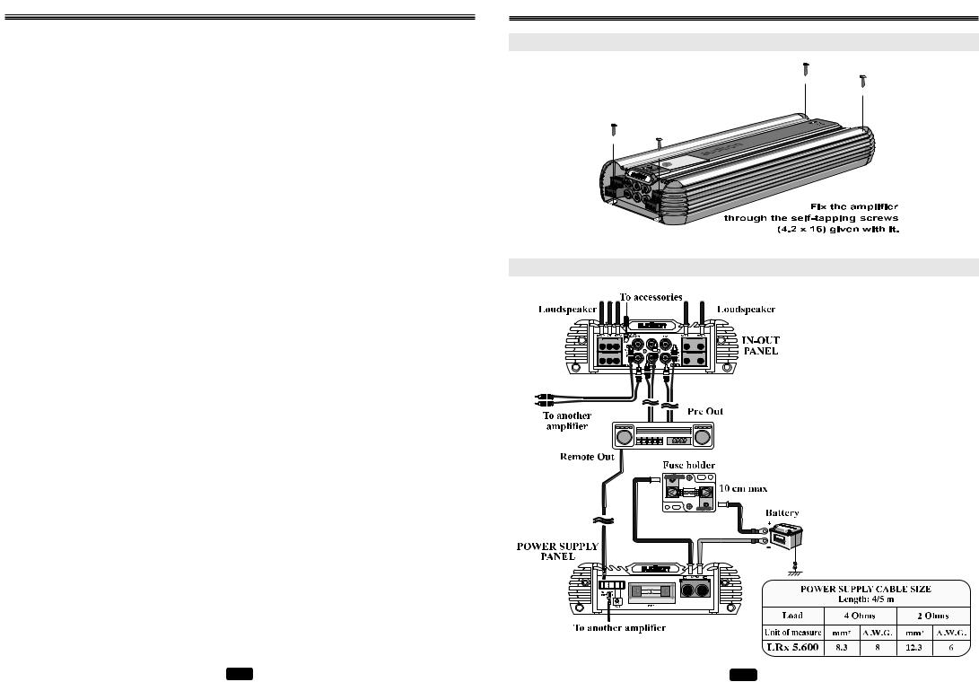
AMPLIFIER FIXING
ELECTRIC CONNECTIONS
CAUTION!
For the system safer protection, we recommend the use of a strip fuse on the cable that connects the battery positive pole to the amplifier POWER (+) terminal block. This fuse has to be installed about 10 cm far from the battery; its value will have to be equal or slightly higher (+10% approx.) than consumption @13.8 VDC, according to the different configurations (see “Technical features”).
It will have to be equal to the sum of the values of all fuses in case system consists of several amplifiers or in case amplifiers have several fuses.
LRx 5.600 FUSE: 50A
21
 Loading...