


 Loading...
 USER’S MANUAL
rev. 1.5 e
Update for:
• bit One.1
• Pc Software 1.5
• bit One Firmware 1.5.0.0
• DRC Firmware 1.50
• Accessories: SFC / DRC cable extension Kit
• Instruction for Windows XP, Vista, 7, 8, 8.1, 10 installation

USER’S MANUAL |
bit One / |
Index
1. |
PRODUCT DESCRIPTION.............................................................................................................................................. |
3 |
|
2. |
PACKAGING CONTENTS............................................................................................................................................... |
3 |
|
3. BIT ONE and DRC INSTALLATION.............................................................................................................................. |
4 |
||
4. |
CONNECTION PANELS - DESCRIPTION................................................................................................................... |
5 |
|
|
4.1 |
Input Signals........................................................................................................................................................... |
5 |
|
4.2 |
Output Signal.......................................................................................................................................................... |
6 |
|
4.3 |
Inputs - remote control outputs and power supply........................................................................................ |
6 |
5. |
CONNECTIONS................................................................................................................................................................ |
7 |
|
|
5.1 |
Power supply and remote turn on...................................................................................................................... |
7 |
|
5.2 |
How to turn on/off the bit One............................................................................................................................ |
7 |
|
5.3 |
Personal computer and Digital Remote Control (DRC)................................................................................. |
7 |
|
5.4 |
Low Level and Digital input signals................................................................................................................... |
8 |
|
5.5 |
High Level input signals....................................................................................................................................... |
9 |
|
5.6 |
Output Signals...................................................................................................................................................... |
10 |
6. BIT ONE SOFTWARE AND DRIVERS - INSTALLATION GUIDE........................................................................... |
11 |
||
|
6.1 |
Software installation guide................................................................................................................................ |
11 |
|
6.2 |
Ac-Link drivers installation on Windows XP, Vista, 7................................................................................... |
13 |
|
6.3 |
Ac-Link drivers installation on Windows 8, 8.1, 10....................................................................................... |
17 |
|
6.4 |
Troubleshooting section for software installation........................................................................................ |
24 |
7. BIT ONE SOFTWARE AND DRIVERS UNINSTALLATION GUIDE........................................................................ |
25 |
||
|
7.1 |
bit One software uninstall.................................................................................................................................. |
25 |
|
7.2 |
How to uninstall the Ac-Link drivers with Windows XP.............................................................................. |
25 |
|
7.3 |
How to uninstall the Ac-Link drivers with Windows Vista.......................................................................... |
26 |
|
7.4 |
How to uninstall the Ac-Link drivers with Windows 7................................................................................. |
27 |
|
7.5 |
How to uninstall the Ac-Link drivers with Windows 8, 8.1, 10................................................................... |
28 |
8. HOW TO CONNECT THE BIT ONE TO THE PC........................................................................................................ |
29 |
||
|
8.1 |
OFFLINE mode..................................................................................................................................................... |
29 |
|
8.2 |
Starting up the bit One software in TARGET mode - warnings................................................................. |
30 |
|
8.3 |
TARGET mode...................................................................................................................................................... |
30 |
|
8.4 |
Selecting the MASTER mode Low Level inputs ........................................................................................... |
31 |
|
8.5 |
Selecting the MASTER mode High Level inputs........................................................................................... |
35 |
9. HOW TO SETUP THE BIT ONE WITH THE PC......................................................................................................... |
38 |
||
|
9.1 |
Features................................................................................................................................................................. |
38 |
|
9.2 |
Main menu File..................................................................................................................................................... |
39 |
|
9.3 |
Main menu Config............................................................................................................................................... |
40 |
|
9.4 |
Channel Map........................................................................................................................................................ |
41 |
|
9.5 |
Select a Channel.................................................................................................................................................. |
42 |
|
9.6 |
Filter Settings....................................................................................................................................................... |
43 |
|
9.7 |
Display and Settings........................................................................................................................................... |
45 |
|
9.8 |
Selected Input ..................................................................................................................................................... |
45 |
|
9.9 |
Ext. Source EQ...................................................................................................................................................... |
46 |
|
9.10 |
Set Distance and Delay...................................................................................................................................... |
48 |
|
9.11 |
Output Level.......................................................................................................................................................... |
50 |
|
9.12 |
Grafic Equalizer.................................................................................................................................................... |
51 |
|
9.13 |
Dynamic Equalization Wizard........................................................................................................................... |
52 |
|
9.14 |
Memory................................................................................................................................................................. |
54 |
10. TROUBLESHOOTING................................................................................................................................................... |
55 |
||
|
10.1 |
Synchronization with the PC............................................................................................................................. |
55 |
|
10.2 |
Background noise................................................................................................................................................ |
55 |
|
10.3 |
Firmware upgrade - Rescue Mode.................................................................................................................. |
55 |
11. STARTING UP THE BIT ONE SOFTWARE IN TARGET MODE IN FINALIZED BIT ONES................................ |
59 |
||
12. DRC - DIGITAL REMOTE CONTROL.......................................................................................................................... |
60 |
||
|
12.1 |
Phone Call............................................................................................................................................................. |
61 |
|
12.2 |
SEL button - function.......................................................................................................................................... |
61 |
|
12.3 |
Bypassing the DRC............................................................................................................................................. |
62 |
|
12.4 |
Upgrade Firmware DRC..................................................................................................................................... |
62 |
13. ACCESSORIES............................................................................................................................................................... |
65 |
||
|
13.1 |
SFC......................................................................................................................................................................... |
65 |
|
13.2 |
DRC cable extension kit..................................................................................................................................... |
66 |
14. TECHNICAL SPECIFICATIONS.................................................................................................................................. |
67 |
||
2
USER’S MANUAL |
bit One / 1/2 |
1. PRODUCT DESCRIPTION
bit One is a signal digital processor essential to maximize the acoustic performance of your Car Audio system. It consists of a 32 bit DSP processor and 24 bit AD and DA converters.
It can be interfaced with any factory system, even in vehicles featuring an integrated audio processor, since, thanks to the de-equalization function, the bit One will send back a linearized signal.
The bit One features 21 signal inputs; 8 Hi-Level, 1 Phone, 6 Low-Level, 4 Aux, 1 Optical Digital, 1 Coax Digital. It provides 8 PRE OUT analog or digital outputs.
Each output channel has a 32 band equalizer available. It also features a 66 frequency steps electronic crossover as well as BUTTERWORTH or LINKWITZ filters with 6-48 dB slopes; a digital time delay line along with an equalizer on each auxiliary input are also available. The user can select adjustments that will allow him to interract with the bit One trough the remote controll device called DRC.
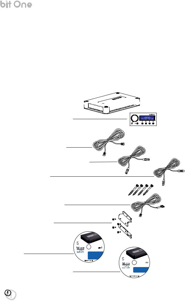
2. PACKAGING CONTENTS
- bit One - Signal Interface Processor 


- DRC (Digital Remote Control) Control Panel
- Printed Quick Start Guide
- 5.0 m / 196,85” AC Link (RJ-12) cable
- 5.0 m / 196,85” AD Link (LAN class 5S - RJ45) cable
- 3.0 m / 118,11” USB cable
-N. 4 4.2 x 38 mm self-tapping, cross head fixing screws 


-4.5 m / 177,16” DRC / ACLink cable
-N. 2 fixing brackets with 2.9 x 6.5 mm self-tapping, cross head screws
-CD ROM with: bit One Software
USB-ACNet drivers
This Advanced Manual (.pdf format) Test tracks
-DVD comprising:
Test tracks encoded with Dolby Digital 5.1
|
|
|
pas |
|
|
|
leoftr |
-ly |
aIt |
|
|
|
|
|
|
ww |
|
|
|
.w |
|
|
|
ele |
|
|
|
rtt |
|
|
|
mo |
|
|
|
ide |
|
|
|
i.a |
|
|
|
-t |
|
|
|
lA |
|
|
|
l |
|
|
|
Rgi |
|
|
|
th |
|
|
|
s |
|
|
|
R |
|
|
|
e |
|
|
|
s |
|
|
|
e |
|
|
|
r |
|
|
|
v |
|
|
|
e |
|
SETUP CD 1.1 |
|
A |
|
||
d |
|
|
|
- |
|
|
|
l |
|
|
|
l |
|
|
|
p |
|
|
|
r |
|
|
|
o |
|
|
|
d |
|
|
|
u |
|
|
|
c |
|
|
|
t |
|
|
|
n |
|
|
|
a |
|
|
|
m |
|
|
|
e |
|
|
|
s |
|
|
|
a |
|
|
|
r |
|
|
|
er |
|
|
|
|
e |
|
|
|
gi |
|
|
|
st |
|
|
|
er |
|
|
|
e |
|
|
|
dt |
||
|
|
rad |
|
|
|
em |
|
|
|
ark |
|
|
|
so |
|
|
|
fth |
|
|
|
eirre |
|
|
|
spe |
|
|
|
|
ctiveh |
|
|
|
olders |
ni odsi
u
a
TEST SIGNALS
Track_01. sine sweep (10 min) Track_02. white noise (15 min) Track_03. pink noise (10 min)
Track_04. sine wave 50 Hz - 0 dB (2 min) Track_05. sine wave 1 kHz - 0 dB (2 min)
CD ROM
Bit One Software 1.1 USB-ACNet Drivers 1.0 Product manual
|
|
|
rttelef |
otarp |
|
|
|
|
|
|
y |
|
|
|
|
- |
|
|
|
.w |
ww |
|
|
|
|
|
|
|
|
ele |
|
|
|
|
rtt |
|
|
|
|
mo |
|
|
|
|
ide |
|
|
|
|
i.a |
|
|
|
|
-t |
|
|
|
|
llA |
|
|
|
|
iR |
|
|
|
|
g |
|
|
|
|
hst |
|
|
|
|
Re |
|
|
|
|
es |
|
|
|
|
r |
|
|
|
|
v |
|
|
|
|
e |
|
|
|
|
d |
|
|
|
|
- |
|
TEST SIGNAL DVD |
||
p |
|
|||
A |
|
|
|
|
l |
|
|
|
|
l |
|
|
|
|
r |
|
|
|
|
o |
|
|
|
|
d |
|
|
|
|
u |
|
|
|
|
c |
|
|
|
|
t |
|
|
|
|
n |
|
|
|
|
a |
|
|
|
|
m |
|
|
|
|
e |
|
|
|
|
s |
|
|
|
|
a |
|
|
|
|
r |
|
|
|
|
er |
|
|
|
|
|
e |
|
|
|
|
gi |
|
|
|
|
s |
|
|
|
|
t |
|
|
|
|
er |
|
|
|
|
e |
|
|
|
|
d |
|
||
|
tr |
|
||
|
|
a |
|
|
|
|
de |
|
|
|
|
m |
|
|
|
|
ark |
|
|
|
|
so |
|
|
|
|
fth |
|
|
|
|
eirr |
|
|
|
|
esp |
|
|
|
|
ecti |
|
|
|
|
veh |
|
|
|
|
|
olders |
|
sinosi
dua
SURROUND TEST SIGNALS 5.1
Track_01. sine sweep (10 min) Track_02. white noise (15 min) Track_03. pink noise (10 min)
Track_04. sine wave 50 Hz - 0 dB (2 min) Track_05. sine wave 1 kHz - 0 dB (2 min)
WARNING: a PC provided with Windows XP, Vista, 7, 8, 8.1 or 10 operating system, 1.5 GHz minimum processor speed and 1 GB RAM minimum memory, are required to install the software and setup the bit One.
3
USER’S MANUAL |
bit One / 3 |
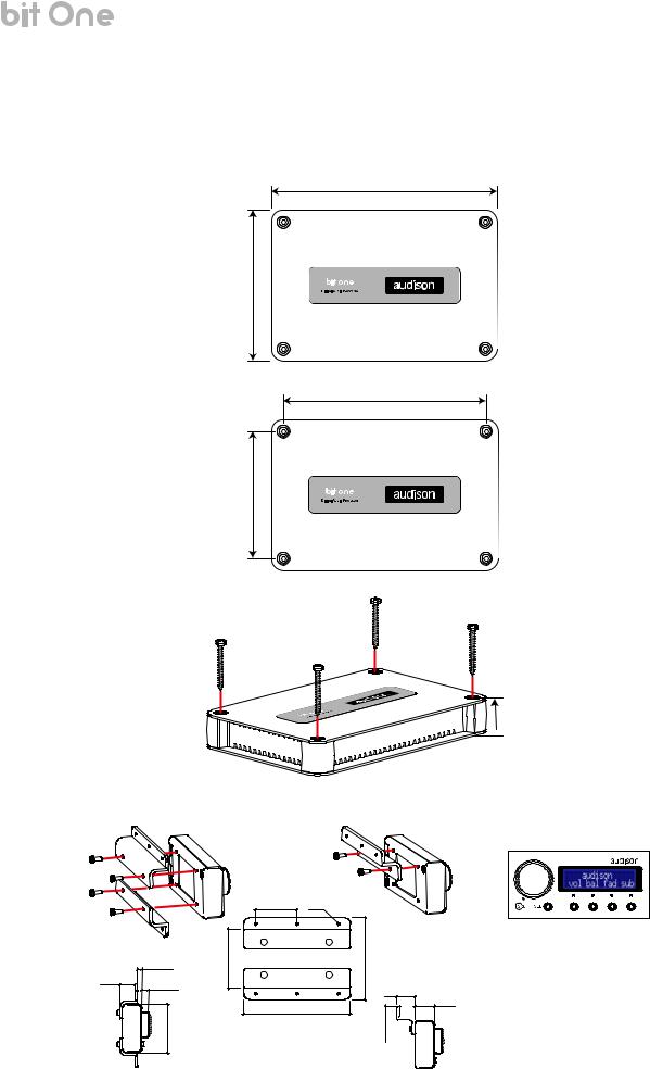
3. BIT ONE AND DRC INSTALLATION
BIT ONE:
External dimensions
Mounting dimensions
225 mm / 8,85”
150 mm / 5,90”
201 mm / 7,91”
126 mm / 4,96”
4.2 x 38 mm
DRC:
How to install the DRC
 32.3 mm 1,27”
(provided)
3.5 mm / 0.14”
13.5 mm / 0.53”
6 mm / 0.23”
43.5 mm / 1.71”
35 mm / 1.38” |
Ø 2 mm / 1/8” |
50 mm / 2” |
mm / 2.68” |
|
68 |
16 mm / 0.63”
17 mm / 0.67”
90 mm / 3.54” 0.49”/ 


mm12.5
WARNING: do not use aggressive cleaning agents or abrasive cloth to clean the display. Simply use a soft cotton cloth lightly damped with water.
4
USER’S MANUAL |
bit One / 4 |
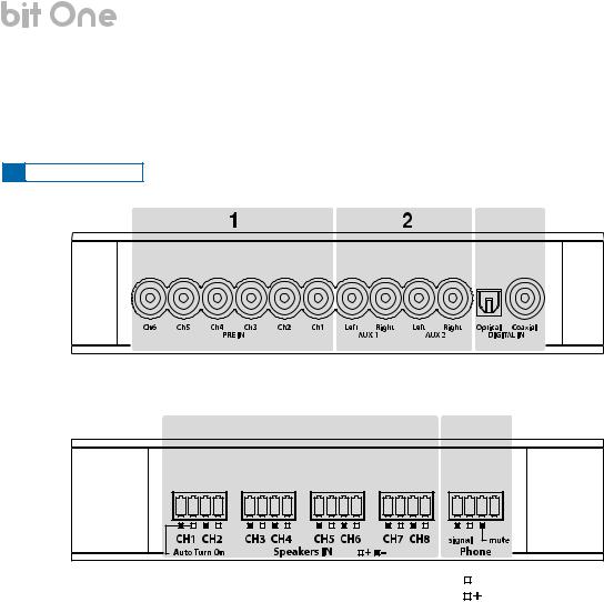
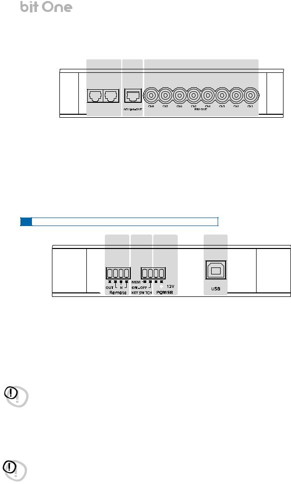
4.CONNECTION PANELS - DESCRIPTION
4.1INPUT SIGNALS
3
4 |
5 |
Remark: Ch1 Auto Turn ON can be |
|
|
|
negative pole (ground) |
|
|
|
||
excluded in the bit One.1 version. |
|
|
|
positive pole |
1.PRE IN low-level MASTER inputs (see section 5.4.1-2)
Ch1 - Ch2 - Ch3 - Ch4 - Ch5 - Ch6
Connect here the RCA cables coming from the main analog signal source. If these inputs are used, the MASTER SPEAKER IN inputs can not be used.
2.AUX1 – AUX2 auxiliary low-level STEREO inputs (see section 5.4.3-4)
Connect here the RCA cables coming from additional analog signal sources.
3.DIGITAL IN S/PDIF digital inputs (see section 5.4.5-6)
The applicable signal must be a 48 kHz/24bit max. STEREO signal. COAXIAL. Connect a 75 ohm shielded cable.
OPTICAL. Connect an optical fibre cable with TOSLINK connector.
4.SPEAKERS IN hi-level MASTER input (see section 5.5.1-2)
Ch1 - Ch2 - Ch3 - Ch4 - Ch5 - Ch6 - Ch7 - Ch8
Connect here the specific cables coming from the power output of the main signal source.
If these inputs are used, the MASTER PRE IN inputs can not be used.
Ch1 features AUTO TURN ON (ART), providing the ability to automatically turn on/off the bit One through the connection with the source speaker outputs. In the bit One.1 version (check label on the bottom of the product) this feature can be disabled (see section 5.5.1).
5.PHONE input for phone hands-free kits (see section 5.5.3)
SIGNAL. Connect the audio output cables coming from the hands-free kit system in use. MUTE. Connect the hands-free kit remote control (MUTE/PHONE MUTE).
5
USER’S MANUAL |
|
|
|
bit One / 4 |
|
|
|
|
|
|
|
4.2 |
OUTPUT SIGNALS |
|
|
|
|
3 |
2 |
1 |
|||
DRC AMPS
1 - AC Link - 2
1.PRE OUT low-level analog signal (see section 5.6.2-3)
Ch1 - Ch2 - Ch3 - Ch4 - Ch5 - Ch6 - Ch7 - Ch8
Connect here the RCA cables going to the system’s amplifiers.
2.AD Link - OUT digital signal (see section 5.6.1-3)
S/PDIF standard digital signal (Ch1÷Ch8) to connect amplifiers provided with appropriate ADLink input.
3.AC Link 1 - 2 Remote Controls
DRC: Connection plug for the remote control panel of the processor functions and the devices connected to the AMPS bus (see section 5.3).
AMPS: Connection bus to control the amplifiers provided with ACLink connection (see section 5.6.1-3).
4.3INPUTS - REMOTE CONTROL OUTPUTS AND POWER SUPPLY
1 |
2 |
|
3 |
4 |
|
|
|
|
|
|
|
|
|
|
|
|
|
|
|
|
|
|
|
|
|
|
|
|
|
1.REMOTE IN-OUT (see section 5.1)
IN: for the processor remote turn-on through one or multiple signal sources, featuring Rem Out control.
OUT: output for the remote turn-on of the other devices/amplifiers connected to the processor.
The REMOTE OUT output current capability is 20 mA. From the REMOTE-IN signal, the processor only takes 7 seconds to supply the signal to the REMOTE OUT output.
IMPORTANT REMARK: current capability of the bit One.1 version (check the label on the bottom of your bit One to know its version) is 130 mA; it can also drive an automotive relay (make sure its absorption is not higher than 130 mA).
WARNING: the bit One must be switched on before the amplifiers connected edit are turned on. It’s necessary to connect the sources Remote Out to the bit One Remote In and then the bit One Remote Out to the Remote In of the other devices/amplifiers connected to the bit One (section 5.1).
2.KEY SWITCH ignition key connection (see section 5.2.3-4)
MEM: it stores the processor status when it is turned off.
ON - OFF: it turns the processor on and off when the vehicle turn on/off ignition key is turned.
3.POWER power supply connection (section 5.1)
- 12V + : Positive and negative connection terminal for car 12 V power supply.
WARNING: make sure the connection polarity is as indicated on the terminals. A mis-connection may result in damage to the bit One. After applying a 12V power, wait at least 20 seconds before turning the bit One on.
4. USB (section 5.3)
USB (B) connection plug, to connect the processor to a PC and manage its functions through the bit One software. The connection standard is USB 1.1/2.0 compatible.
6
USER’S MANUAL |
bit One / 5 |
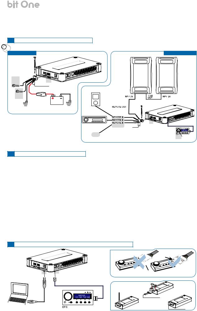
5. CONNECTIONS
5.1 POWER SUPPLY AND REMOTE TURN-ON

 ATTENTION: to power the bit One, use 1 mm2 (16 AWG) min. cables.
POWER SUPPLY
(section 5.2)
4
|
L: 7 mm (5/16”) |
|
|
3 |
Fuse Holder |
|
|
(section 5.2) |
Not provided |
12V |
|
|
|
||
|
suggested fuse |
|
|
|
|
|
|
Ground |
T1A-Delayed |
Battery |
Ground |
|
S R E I F I L P M A
REMOTE TURN ON
Remark: The bit One is internally |
|
|
protected by a fuse-resistor soldered on |
2 (section 5.2) |
|
its printed circuit board. To replace it, |
L: 7 mm (5/16”) |
|
contact a service centre. The application |
or other |
|
of an external fuse is recommended, |
||
|
||
though it is not indispensable. |
|
5.2 HOW TO TURN ON/OFF THE BIT ONE
1
(section 5.2)
The bit One is on when the Audison logo lights up in blue. After receiving the turn-on input the bit One takes 9 seconds to become operative. It can be turned on / off in the following ways:
1.Push the DRC main control switch (to turn on). Keep the DRC main control knob pressed (to shut down). In this case no other connections Remote In / KEY SWITCH are required, but they can coexist (see section 12).
2.Connecting one of the Remote In plugs using a Remote signal coming from one source, the KEY SWITCH connection is not required, but it can coexist.
3.Through the KEY SWITCH ON OFF. Every time you turn on / off the car ignition key, the bit One will turn on / off. If this control is used, KEY SWITCH MEM can not be used.
4.Through the KEY SWITCH MEM. If the bit One was turned off through the KEY SWITCH MEM connection, it will automatically turn on again by turning the KEY SWITCH MEM itself. If it was turned off through a different method (ex. through the Remote or the DRC) while the KEY SWITCH MEM was still active, the bit One will not turn on again through the KEY SWITCH MEM; you will have to turn it on through either the DRC or the Remote. If you use the KEY SWITCH MEM, the KEY SWITCH ON OFF can not be used.
5.Through the SPEAKER IN CH1. The AUTO TURN ON (ART) activates by connecting the amplified head unit output to the SPEAKER IN CH1 input channel, the ART can be disabled on the bit One.1 (check the label on the bottom of your bit One to know its version) by opening the product and removing the jumper as shown in the picture (see section 5.5.1).
6.Automatically through the hands-free phone kit (see section 5.5.3), with the bit One “mute” control turned off.
5.3PERSONAL COMPUTER and DIGITAL REMOTE CONTROL (DRC)


 TO THE SYSTEM’S AMPLIFIER
ACLink PROVIDED
DRC IN
DRC / ACLink cable
(4,5 m / 177,16” in provided see section 13.2)
NO


 SI
SI


DRC/ACLink cable (provied)

 USB cable
(provided)
7

USER’S MANUAL
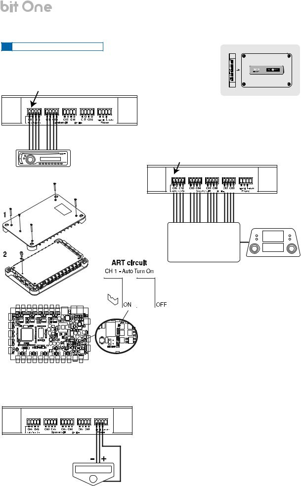
5.4 LOW-LEVEL AND DIGITAL INPUT SIGNALS
1.PRE IN - Ch1/Ch6 analog STEREO signal (select 2 signals from Ch1 and Ch6)
L |
R |
 Pre Out
Source (MAX 6 PRE OUT)
bit One / 5
bit One Bottom Side
2. PRE IN - Ch1/Ch 6 - analog Audio Car Theatre
3. AUX 1 - Left/Right - analog STEREO signal
C
BSE
UN REAR FRONT
T
E
R Multi Channel Source
Analog Preamplified Signal
Auxiliary Stereo
Preamplifier Source
5.DIGITAL IN OPTICAL
Digital S/PDIF STEREO signal
Signal: STEREO Max 48 kHz / 24 bit 


 TOSLINK
  connector
Optical fiber
DIGITAL IN - WARNING: the digital inputs accepts up to 48 kHz / 24 bit stereo PCM signals. So DOLBY DIGITAL (AC3) multi-channel signals coming from audio/video sources (such as the audio of a film in DVD) or DTS can not be reproduced. The output of these devices will therefore be set in STEREO mode for the signal to be reproduced. If digital signals at frequency higher than 48 kHz (96 - 192 kHz) are supplied, the bit One locks up. In that case, turn the bit One off, supply the adequate signal and turn it on again.
4. AUX 2- Left/Right – analog STEREO signal
Auxiliary Stereo
Preamplifier
Source
6. DIGITAL IN COAXIAL
Digital S/PDIF STEREO signal
Signal: STEREO Max 48 kHz / 24 bit
Stereo Source
Digital Signal
75 ohm coax cable
8
USER’S MANUAL |
bit One / 5 |
5.5 HIGH-LEVEL INPUT SIGNALS
1. SPEAKER IN Hi-Level STEREO Front + Rear
CH1: Auto Turn On System (ART) (see section 5.2.5)
bit One Left Side
Front 
 Rear
Rear
2. SPEAKER IN Hi-Level MULTICHANNEL
CH1: Auto Turn On System (ART) (see section 5.2.5)
Amplified Source
MAX:
8 amplified channels
Original amplified source
3. CONNECTION WITH HANDS-FREE PHONE KIT
Signal
mute
bit One.1
To deactivate the ART function on Ch1 take out the Jumper as indicated in the picture.
Signal: input compatible with the hands-free kit headphones or speaker output. Sensitivity adjustable via the bit One PC software from 0.6V to 10V RMS.
Mute: bit One on. It gives priority to the phone conversation, allowing to resume the audio reproduction when the phone call is finished.
Mute: bit One off. It turns the bit One on. When a phone call is received, the phone ringing tone is audible after around 9 seconds. Once the phone call is finished, the bit One turns off.
9
USER’S MANUAL |
bit One / 5 |
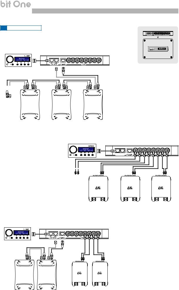
5.6 OUTPUT SIGNALS |
|
|
AMPS |
ADLINK-OUT / ACLINK 2 - AMPS |
1DRC- AC Link - 2 |
|
1. OUTPUT TO AN AMPLIFIERS SYSTEM PROVIDED WITH
ADLINK AND ACLINK CONNECTION (THESIS TH) (see section 8.4.7)
DRC |
ACLink |
ADLink |
Function Control |
Digital Signal |
|
|
|
|
|
|
|
|
|
|
|
|
|
|
|
|
|
|
|
|
|
|
|
|
|
|
|
|
|
|
|
|
|
|
|
|
|
|
|
|
|
|
|
|
|
|
|
|
|
|
|
|
|
|
|
|
|
|
|
|
|
|
Other |
|
|
|
|
TH |
|
|
|
|
|
|
|
|
|
TH |
|
|
|
|
|
|
|
TH |
|
|
|||||
TH amplifier |
|
|
|
|
|
|
|
|
|
|
|
|
|
|
|
|
|
|
|
|
|
|
||||||||
|
|
|
|
amplifier |
|
|
|
|
|
|
|
|
amplifier |
|
|
|
|
|
|
amplifier |
|
|
||||||||
|
|
|
|
|
|
|
|
|
|
|
|
|
|
|
|
|
|
|
|
|
|
|
||||||||
|
|
|
|
|
|
|
|
|
|
|
|
|
|
|
|
|
|
|
|
|
|
|
|
|
|
|
|
|
|
|
|
|
|
|
|
|
|
|
|
|
|
|
|
|
|
|
|
|
|
|
|
|
|
|
|
|
|
|
|
|
|
|
|
|
|
|
|
|
|
|
|
|
|
|
|
|
|
|
|
|
|
|
|
|
|
|
|
|
|
|
|
|
|
|
|
|
|
|
|
|
|
|
|
|
|
|
|
|
|
|
|
|
|
|
|
|
|
|
|
|
|
|
|
|
|
|
|
|
|
|
|
|
|
|
|
|
|
|
|
|
|
|
|
|
|
|
|
|
|
|
|
|
|
|
|
|
|
|
|
|
|
|
|
|
|
|
|
|
|
|
|
|
|
|
|
|
|
|
|
|
|
|
|
|
|
bit One Top Side
Remark: the output channels are 8 in total. The sum of the channels of the amplifiers connected must not exceed 8.
To increase the number of channels, however, the same function (AMP ID) can be assigned to more than one amplifier
2. OUTPUT TO A PRE PROVIDED AMPLIFIERS SYSTEM
(see section 8.4.7) |
DRC |
DRC |
AMPS |
1 - AC Link - 2 |
|
Other amplifier
3.OUTPUT TO AN AMPLIFIERS SYSTEM PROVIDED WITH AD LINK CONNECTIONS (THESIS TH) AMPLIFIERS SYSTEM PROVIDED WITH PRE INPUT (see section 8.4.7)
DRC |
ACLink |
ADLink |
|
Function Control |
|||
|
Other |
|
|
|
|
|
|
|
|
|
|
|
|
|
|
|
|
|
|
|
|
|
|
|
|
|
|
|
|
|
|
|
|
|
|
|
|
|
|
|
|
|
|
|
|
|
|
|
|
|
|
|
|
|
|
|
|
|
|
|
|
TH |
|
|
|
|
|
|
|
TH |
|
|
||||
|
|
|
|
|
|
|
|
|
|
|
|
|
||||||
TH amplifier |
|
|
|
|
|
|
|
|
|
|
|
|
||||||
|
|
|
amplifier |
|
|
|
|
|
|
amplifier |
|
|
||||||
|
|
|
|
|
|
|
|
|
|
|
||||||||
|
|
|
|
|
|
|
|
|
|
|
|
|
|
|
|
|
|
|
|
|
|
|
|
|
|
|
|
|
|
|
|
|
|
|
|
|
|
|
|
|
|
|
|
|
|
|
|
|
|
|
|
|
|
|
|
|
|
|
|
|
|
|
|
|
|
|
|
|
|
|
|
|
|
|
|
|
|
|
|
|
|
|
|
|
|
|
|
|
|
|
|
|
|
|
|
|
|
|
|
|
|
|
|
|
|
|
|
|
|
|
|
|
|
Remark: in total, 8 output channels are available. The sum of the analog and
digital outputs (ADLink) must not exceed the total available channels.
10
USER’S MANUAL |
bit One / 6 |
6.BIT ONE SOFTWARE AND DRIVERS - INSTALLATION GUIDE
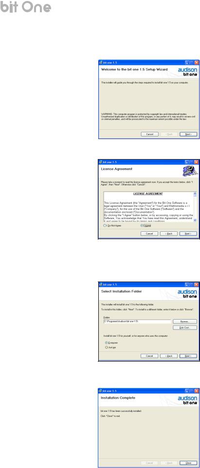
6.1SOFTWARE INSTALLATION GUIDE
1.Insert the “bit One Setup 1.5 CD” into the CD-Player of the PC you are going to use.
2.Windows XP: select “My Computer” from the Windows START menu;
Windows Vista: select “Computer” from the Windows START menu; Windows 7: select “Computer” from the Windows START menu;
Windows 8, 8.1: click on the DESKTOP icon;
Windows 10: select “My Computer” from the DESKTOP.
Windows XP |
Windows Vista |
Windows 7 |
Windows 8, 8.1 |
Windows 10 |
3.Windows XP: right-click your mouse on the “bit One v.1.5” CD icon and click on “Explore”; Windows Vista: right-click your mouse on the “bit One v.1.5” CD icon and click on “Explore”; Windows 7: right-click your mouse on the “bit One v.1.5” CD icon and click on “Open”;
Windows 8, 8.1: double click on the Computer icon.
Windows 10: right-click your mouse on the “bit One v.1.5” CD icon and click on “Open”
Windows XP |
Windows Vista |
Windows 7 |
Windows 8, 8.1 |
Windows 10 |
4.Windows XP: double click on the “setup” icon; Windows Vista: double click on the “setup” icon; Windows 7: double click on the “setup” icon;
Windows 8, 8.1: select the CD ROM drive an double click on “setup” icon; Windows 10: double click on the “setup” icon
Windows XP |
Windows Vista |
Windows 7 |
Windows 8, 8.1 |
Windows 10 |
11
USER’S MANUAL |
bit One / 6 |
5.Windows XP, Windows Vista, Windows 7, Windows 8, 8.1, Windows 10: select NEXT to go on with the installation, CANCEL to interrupt it;
6. Windows XP, Windows Vista, Windows 7, Windows 8, 8.1, Windows 10: select I Agree and then NEXT;
7.Windows XP, Windows Vista, Windows 7, Windows 8, 8.1, Windows 10: select
-Everyone if you have the system administrator privileges, so, once installed, the program can be used by anyone who uses that PC;
-Just me if you want that, once installed, the program can only be used by yourself as single system user. Then click on NEXT;
8.Windows XP, Windows Vista, Windows 7, Windows 8, 8.1, Windows 10:
go on and complete the installation procedure, then click on CLOSE to exit the installation;
9.The bit One PC software is now installed in your system. Leave the “bit One Setup 1.5 CD” in the CD-Player and proceed with the installation of the Drivers as detailed out in the following chapter 6.2.
12
USER’S MANUAL |
bit One / 6 |
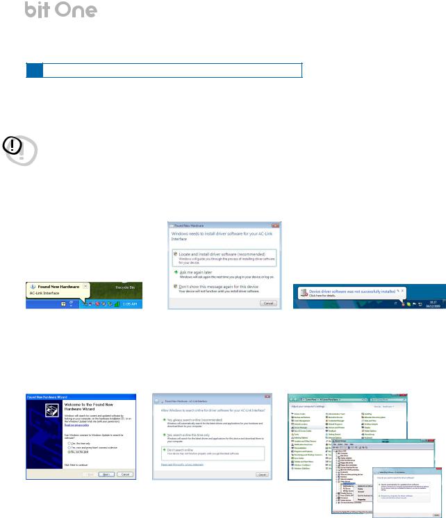
6.2AC-LINK DRIVERS INSTALLATION ON WINDOWS XP, Vista, 7
1.Turn the bit One on.
2.Connect the USB cable located on the appropriate connector on the bit One to the USB available on the PC.
WARNING: When connecting a PC laptop via a USB cable to the bit One being the device turned on, the laptop has to work with its own battery, keeping it disconnected from the mains adapter (external power supply). Once the connection between the PC laptop and the bit One is established, you can immediately connect the computer, if necessary, through the mains adapter.
3.Windows XP: The PC will recognise the bit One interface and will ask you to install the driver; Windows Vista: Click on “Locate and install driver software (recommended)”;
Windows 7: The PC will recognise the bit One interface and will ask you to install the driver;
Windows XP |
Windows Vista |
Windows 7 |
4.Windows XP: select “No, not this time” and click on “Next”; Windows Vista: click on “Don’t search online”;
Windows 7: select START =>Control Panel =>Device Manager, right click your mouse on the “AC-Link interface” and select “Update driver software”=>“Browse my computer for driver software”;
Windows XP |
Windows Vista |
Windows 7 |
13
USER’S MANUAL |
bit One / 6 |
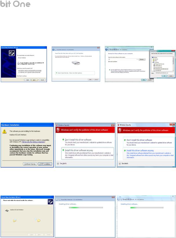
5.Check if the bit One Setup CD is inside the CD-ROM drive
Windows XP: select “Install software automatically” then click on “Next”; Windows Vista: click on “Next”;
Windows 7: click the “Browse“ button to locate the setup CD, select the CD “bit One V_15”, click on “OK”, then on “Next”;
Windows XP |
Windows Vista |
Windows 7 |
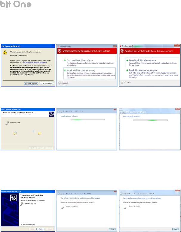
6.The following window regarding the driver certification warning will show up.
Windows XP: click on “Continue Anyway”;
Windows Vista: click on “Install this driver software anyway”; Windows 7: click on “Install this driver software anyway”;
Windows XP |
Windows Vista |
Windows 7 |
7. The system will install the ACLink interface drivers:
Windows XP |
Windows Vista |
Windows 7 |
14
USER’S MANUAL |
bit One / 6 |
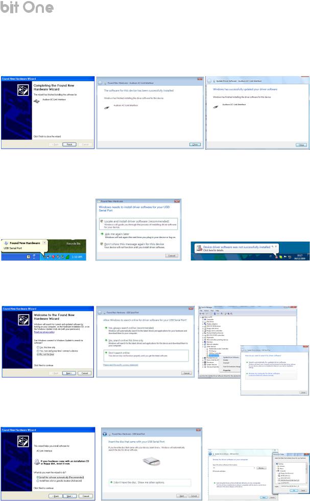
8.If the procedure was successfully completed, the system will notify you that the driver installation has been completed. Windows XP: click on “Finish”;
Windows Vista: click on “Close”; Windows 7: click on “Close”;
Windows XP |
Windows Vista |
Windows 7 |
9.Windows XP:The system will now recognise the virtual serial port connected to the bit One and will ask you to install the driver;
Windows Vista: Click on “Locate and install driver software (recommended)”;
Windows 7: The system will now recognise the virtual serial port connected to the bit One and will ask you to install the driver;
Windows XP |
Windows Vista |
Windows 7 |
10.Windows XP: select “No, not this time” and click on “Next”; Windows Vista: click on “Don’t search online”;
Windows 7: select START =>Control Panel =>Device Manager, right click your mouse on the “USB Serial port” and select “Update driver software”=>“Browse my computer for driver software”;
Windows XP |
Windows Vista |
Windows 7 |
Check if the bit One Setup CD is inside the CD-ROM drive.
Windows XP: select “Install software automatically” then click on “Next”; Windows Vista: click on “Next”;
Windows 7: click the “Browse “ button to locate the setup CD, select the CD “bit One V_15”, click on “OK”, then on “Next”;
Windows XP |
Windows Vista |
Windows 7 |
15
USER’S MANUAL |
bit One / 6 |
12. The following window regarding the driver certification warning will show up.
Windows XP: click on “Continue Anyway”;
Windows Vista: click on “Install this driver software anyway”; Windows 7: click on “Install this driver software anyway”;
Windows XP |
Windows Vista |
Windows 7 |
13. The system will install the ACLink drivers:
Windows XP |
Windows Vista |
Windows 7 |
14. If the procedure was successfully completed, the system will notify you that the driver installation has been completed. Windows XP: click on “Finish”;
Windows Vista: click on “Close”; Windows 7: click on “Close”;
Windows XP Windows Vista Windows 7
15. The installation of the bit One software and driver is now completed (see section 8).
16
USER’S MANUAL |
bit One / 6 |
6.3 AC-LINK DRIVERS INSTALLATION ON WINDOWS 8, 8.1, 10
Remark: The following procedure will temporary disable Windows driver signature enforcement, to allow the AC-Link drivers installation. The driver signature enforcement will be enabled again with the next reboot. The procedure has to be performed only once: after the AC-Link driver installation is completed, it is NOT necessary to
repeat this procedure again every time you want to connect and use the bit One.
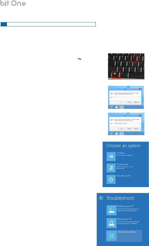
1.Check if the bit One Setup CD is inside the CD-ROM drive
2.Press and keep pressed down the Windows key on the
keyboard (it is located at the bottom left side, look for the  symbol). Then, press the R key.
3.The following dialogue window will appear:
4.Type shutdown.exe /r /o /f /t 00 in the “Open” field and click on “OK”:
5.The following screen will be shown. Click on “Troubleshoot”:
6. The following screen will be shown. Click on “Advanced options”:
17
USER’S MANUAL |
bit One / 6 |
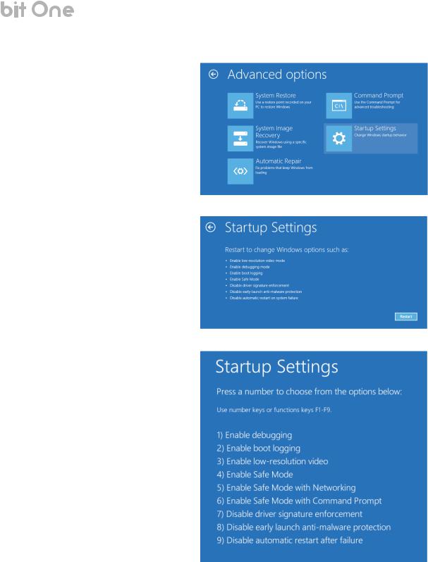
7.The following screen will be shown. Click on “Startup Settings”:
8.The following screen will be shown. Click on “Restart”.
9.The PC will reboot. The following screen will be shown during reboot. Press “7” (Disable driver signature enforcement) and wait for complete Windows startup.
18
USER’S MANUAL |
bit One / 6 |
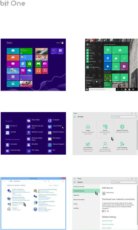
10.Windows 8, 8.1: Right-click on the Windows Start screen. “All apps” key will show on the bottom right angle of the screen. Click it:
Windows 10: Click on the Windows Start screen. Locate “Settings” and click on it:
Windows 8, 8.1 |
Windows 10 |
11.Windows 8, 8.1: The screen will show all the icons. Locate the “Control Panel” icon and click on it: Windows 10: Locate the “Devices” icon and click on it:
Windows 8, 8.1 |
Windows 10 |
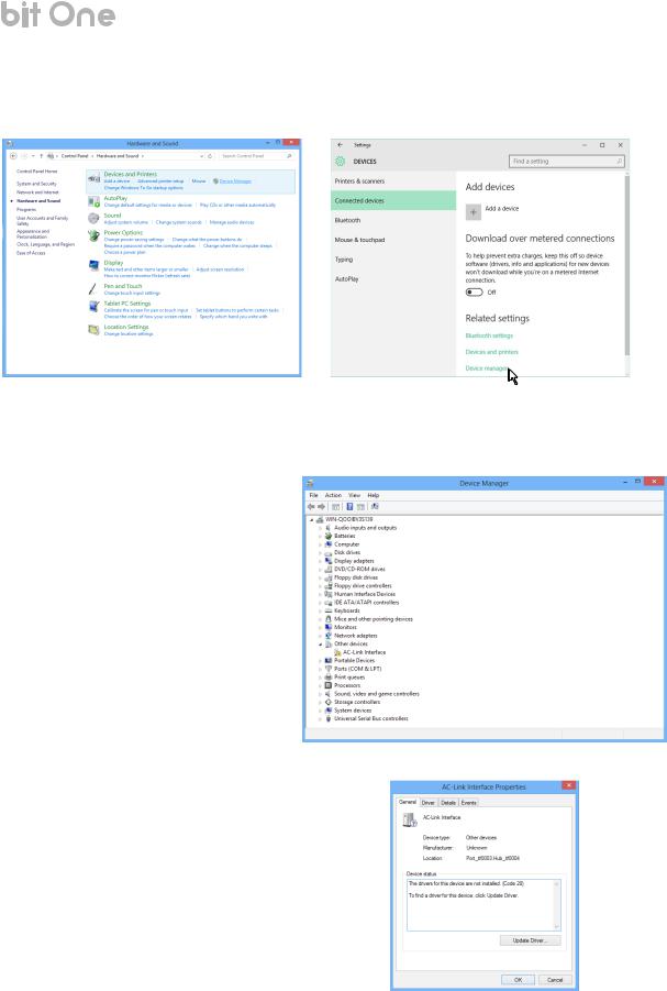
12.Windows 8, 8.1: The Control Panel will show up. Click on “Hardware and Sound”: Windows 10: The Device menu will show up. Click on “Connected devices”:
Windows 8, 8.1 |
Windows 10 |
19
USER’S MANUAL |
bit One / 6 |
13.Windows 8, 8.1: Click on “Device Manager”: Windows 10: Click on “Device Manager”:
Windows 8, 8.1 |
Windows 10 |
14.Power on the bit One processor and connect the USB to the PC.
15.The Control Panel will show the “AC-Link interface” with an exclamation mark. Double click on “AC-Link interface”:
16.The following dialogue window will be shown. Click on “Update Driver…”
20
USER’S MANUAL |
bit One / 6 |
17. Click on “Browse my computer for driver software”:
18.Browse for the AC-Link Driver v1_1 previously copied as per step nr. 2 of this guide, and click on “OK”:
19. Click on “Next”:
20.The following warning will show up, this is normal. Click on “Install this driver software anyway”:
21
Loading...