

Audio2000's AWM6526U, AWR6526U, AWX6526U Owner's Owner's
®
Thank you for purchasing the Audio2000'S professional four-channel UHF
wireless system with 16 adjustable frequencies! For the best results and the
utmost satisfaction from your new unit, please read this manual thoroughly, and
retain it for future reference.
OWNER'S MANUAL
AWM6526U
PROFESSIONAL FOUR-CHANNEL
UHF WIRELESS SYSTEM WITH 16
ADJUSTABLE FREQUENCIES

TABLE OF CONTENTS
Warning .......................................................................... 1
Precautions ..................................................................... 1
Package Contents ............................................................ 2
Quick Setup ..................................................................... 3
Features ......................................................................... 6
System Configurations ..................................................... 7
System Functions ............................................................ 8
Operation - AWR6526U .................................................... 8
Operation - AWX6526U ................................................... 10
Operation Notes ............................................................. 12
Specifications ................................................................ 13
Troubleshooting ............................................................. 14
Service Information ........................................................ 16
WARNING
To prevent fire or shock hazard, do not expose the
unit to rain or moisture.
Dangerously high voltages are present inside the
unit. Do not open the cabinet. Refer servicing to
qualified personnel only.
PRECAUTIONS
On Safety
* Operate only on designated AC power supply (120V AC in North
America).
* Should any liquid or solid object fall into the cabinet, unplug the
unit and have it checked by qualified personnel before operating
it any further.
- 1-

* Unplug the unit from the wall outlet or set the Master switch to
OFF if it is not to be used for several days.
* To disconnect the cord, pull it out by the plug. Never pull the cord
itself.
On Installation
* Allow adequate air circulation to prevent internal heat build-up.
Do not place the unit on surfaces (rugs, blankets, etc.) or near
materials (curtains, draperies) that may block the ventilation
holes.
* Do not install the unit in a location near heat sources such as
radiators or air ducts, or in a place subject to direct sunlight,
excessive dust, mechanical vibration or shock.
On Repackaging
Do not throw away the carton and packing materials. They make
an ideal container in which to transport the unit. When shipping the
unit to another location, repack it as it was originally packed at the
factory.
Items Quantities
AWR6526U Receiver 1
Wireless Transmitters 4
(Handheld
)
AC/DC Adaptor 1
Antennas 2
¼” to ¼” Cable 1
Rack-Mount Ear Kit 1
AA Batteries (Two for Each Transmitter) 8
Owner's Manual 1
Microphones and/or Body-Pack
Transmitters
- 2-
PACKAGE CONTENTS

- 3-
A. Remove packing material
B. Install the AWR6526U receiver
1. Place the AWR6526U receiver at a location at least 3.5 feet (1 meter)
away from the ground and all the walls. Also, keep the AWR6526U
receiver away from any electro-magnetic noise sources as far as
possible.
2. Mount both the antennas onto the left and right TNC antenna jacks. Make
sure that any of the antennas is not enclosed in a large metal body.
3. Plug the supplied AC/DC adaptor 12VDC output connector to the
AWR6526U receiver's DC input, and then plug the AC input of the
adaptor to a 120V AC outlet (North America).
4. Connect the outputs of the AWR6526U receiver to microphone inputs of a
mixer or a sound system. In order to do so, (1) you could use the
supplied microphone cable (a cable with ¼” connectors on both ends) to
connect from the unbalanced output (an ¼” jack) to an ¼” microphone
input on a mixer or a sound system; or (2) you could get four balanced
microphone cables (cables with a male XLR connector at one end and a
female XLR connector on the other end; not included in the package) to
connect from all four balanced outputs (male XLR jacks) to four balanced
microphone inputs (female XLR jacks) on a mixer or a sound system.
5. Turn all four audio level adjustment knobs all the way to the minimal
audio position. Press the power On/Off switch to turn on the AWR6526U
receiver. After the power of the AWR6526U receiver is turned on, the
power LED indicator will be turned on. (Note: The audio level adjustment
knobs will be adjusted to its optimal position after the transmitters are
turned on as discussed in the following section.)
C. Set up the transmitters
QUICK SETUP

(a) Set up the handheld transmitter
1. Open the battery cover of the handheld transmitter by sliding the battery
cover out.
2. Place two 1.5V AA batteries into the battery housing with the battery
polarity orientation as indicated.
3. Place the battery cover back on the handheld transmitter by sliding the
battery cover back in.
4. Turn on the power of the handheld transmitter.
(b) Set up the body-pack transmitter
1. Open the battery cover of the body-pack transmitter by pushing the latch
button (refer to numerals 31 & 32 on pages 11 and 12) inwards (There is a
concaved opening and the latch button is at the lower side of the
opening) and flipping open the battery cover.
2. Place two 1.5V AA batteries into the battery compartment with the battery
polarity orientations as indicated.
3. Plug the supplied headset or lavalier microphone into the microphone
input (a mini XLR jack) on the body-pack transmitter. When the lavalier
microphone is used, the AUDIO INPUT ATTENUATION SWITCH (refer
to numeral 27 on page 11) needs to be set to the 0dB position. When the
headset microphone is used, the AUDIO INPUT ATTENUATION
SWITCH needs to be set to the -10dB position.
4. Flip the cover down in the direction toward the latch button to close the
battery cover.
5. Turn on the power of the body-pack transmitter. The green LED indicator
will be turned on.
D. Setting up the AWM6526U system
1. The best wireless reception can be achieved by selecting the DIP
switch setup to all channels on the AWR6526U receiver (Selections 0
through 7; Totally 8 selections) as follows:
- 4-
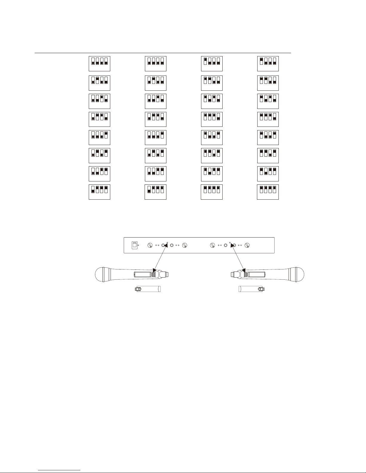
(NOTE: 0 = DIP Switch Down; 1 = DIP Switch Up)
2. If the transmitters need to have their frequencies adjusted to match
to the receiver frequencies, utilize the infrared signal windows as
follows:
Following the previous sections to open the battery covers of the
transmitters (either handheld or body-pack). Keep both transmitters'
power on. Press the Channel A Sync button (refer to numeral 6 on page 8)
and then align the INFRARED SIGNAL RECEIVING WINDOW (refer to
numeral 20 on page 10 for handheld transmitter and numeral 26 on page
11 for body pack transmitter) to the IR AB Window (refer to numeral 7 on
pages 8 and 9) of the AWR6526U receiver, the above transmitter will be
synchronized to the Channel A frequency and the Channel A RF LED light
(Green, refer to numeral 4 on page 8) will be turned on to indicate that the
above transmitter's signal has been received by the receiver. Press the
Channel B Sync button and then align the INFRARED SIGNAL
RECEIVING WINDOW of the second transmitter to the IR AB Window of
the AWR6526U receiver, the above transmitter will be synchronized to the
Channel B frequency and the Channel B RF LED light (Green) will be
turned on to indicate that the above transmitter's signal has been
received by the receiver. Press the Channel C Sync button and then align
the INFRARED SIGNAL RECEIVING WINDOW of the third transmitter
Selection Channel A Channel B Channel C Channel D
Number DIP Switches DIP Switches DIP Switches DIP Switches
0
1
2
3
4
5
6
7
4
321
4
321
4
321
4
321
4
321
4
321
4
321
4
321
4
321
4
321
4
321
4
321
4
321
4
321
4
321
4
321
4
321
4
321
4
321
4
321
4
321
4
321
4
321
4
321
4
321
4
321
4
321
4
321
4
321
4
321
4
321
4
321
( )For Syn c A or B ( )For Syn c C or D
- 5-
 Loading...