

Page 1
M
O
U
S
I
C
VL
M
C
I
S
MAT
E
R
VO
M
E
LU
b
#
W
N
T
U
RL
H
GH
L
O
A
A I
A
I
TN
P
U
B
AKJ7003
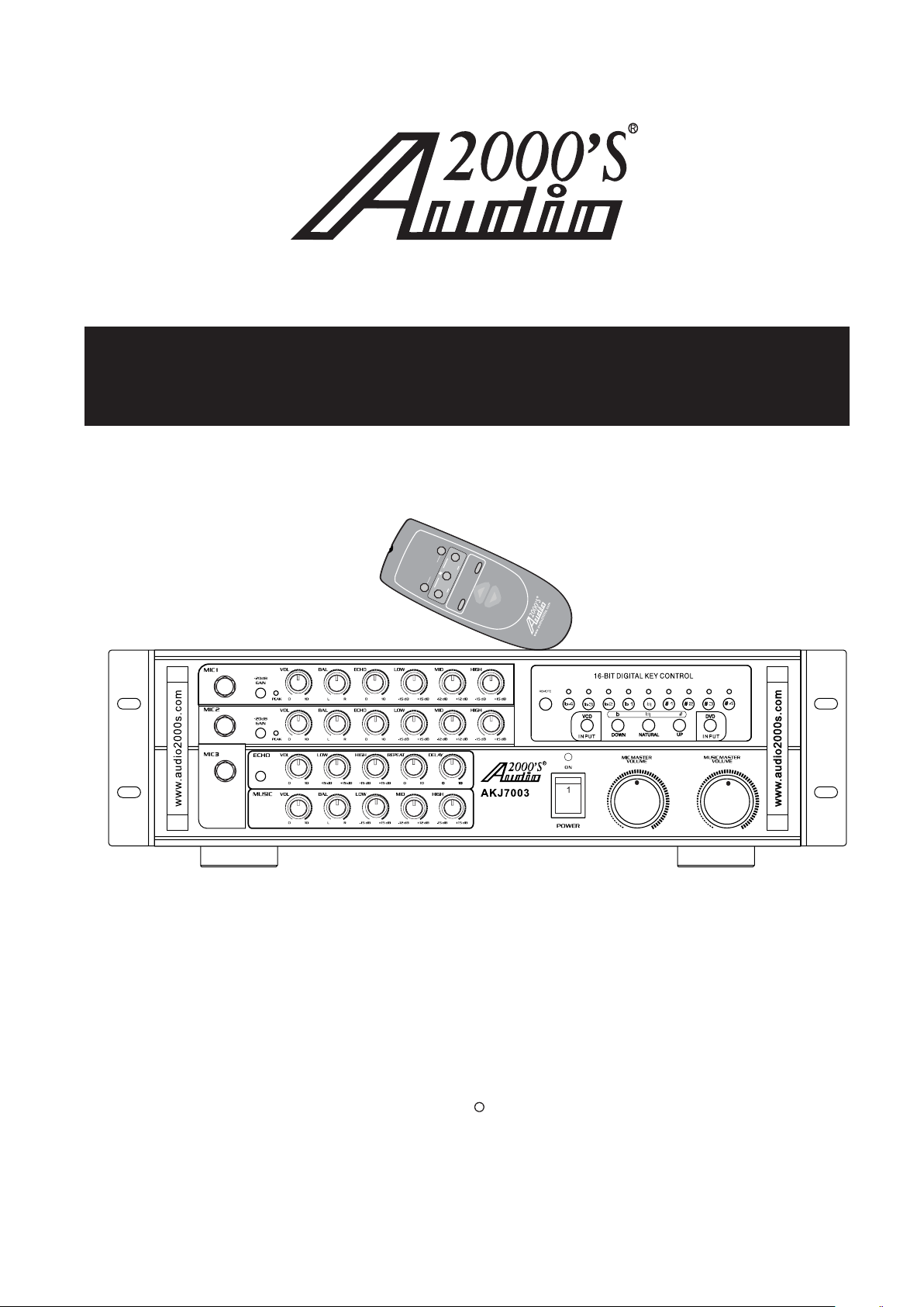
Professional Karaoke Mixing Amplifier with
Digital Echo & Key Controls
OWNER’S MANUAL
B
A
GHL
T
U
+-
H
P
N
I
A I
UR L
C
ER
T
T
A
S
O
M
A
VL
+
C
I
M
I
W N
S
O
-
U
VO ME
M
LU
A
003C
7-01
C
Thank you for purchasing the Audio2000'S
with Digital Echo & Key Controls
! To achieve maximum performance from your new
Professional Karaoke
Mixing Amplifier
with Digital Echo &
Key Controls
R
Professional Karaoke Mixing Amplifier
0
unit, please read this manual thoroughly, and retain it for future reference. For
more information, please visit our website (www.audio2000s.com).
Page 2

TABLE CONTENTS:
WA RNING AND SAFETY INSTRUCTION.......................................
FEATURES ................................................................................
HANDLING PREC AUTIONS ........................................................
BEFORE CONNECTIONS ............................................................
DESCRIPTIONS AND FUNCTIONS
● FRONT PANEL ......................................................................
● REAR PANEL .........................................................................
SPEAKER CONNECTIONS ..........................................................
SYSTEM CONNECTIONS ...........................................................
GENERAL OPERATION ..............................................................
REMOTE CONTROL COMMANDER..............................................
SAFETY PREC AUTIONS .............................................................
MAINTENANCE ........................................................................
TROUBLESHOOTING ................................................................
ETIQUETTE OF SOUND .............................................................
SPECIFICATIONS ......................................................................
SERVICE INFORMATION............................................................
1
3
3
3
4
6
8
9
10
11
12
13
13
13
14
15
IMPORTANT
For your protection,please read these instructions completely, and keep
this manual for future reference.
Carefully observe and comply with all warnings,cautions,and instructions
placed on the equipment or described in the operations instructions to
guard against injury.
Page 3
CAUTION:TO REDUCE THE RISK OF ELECTRIC SHOCK,
REFER SERVICING TO QUALIFIED SERVICE PERSONNEL
WARNIN G
DO NOT REMOVE COVER (OR BACK)
NO USER-SERVICEABLE PARTS INSIDE
The lightning flash with arrowhead symbol,within
an equilateral triangle,is intended to alert the user
to the presence of uninsulated "dangerous voltage"
within the product's enclosure that may be of sufficient magnitude to constitute a risk of electric shock
to persons.
The exclamation point within an equilateral triangle
is intended to alert the user
important operating and maintenance (servicing)
instructions in the literature accompanying the
appliance
to the presence of
TO REDUCE THE RISK OF FIRE OR ELECTRIC SHOCK,
DO NOT EXPOSE THIS APPLIANCE TO RAIN OR MOISTURE
CAUTION:TO PREVENT ELECTRIC SHOCK,MATCH WIDE
BL ADE OF PLUG TO WIDE SLOT, FULLY INSERT.
ATTENTION:POUR EVlTER LES CHOCS ELECTRIQUES
INTRODUlRE LA LAME LA PLUS LARGE DE LA FICHE DANS
LA BORNE CORRESPON-DANTE DE LA PRISE ET POUSSER
JUSQU'AU FOND.
1
Page 4
SAFETY INSTRUCTIONS
READ BEFORE OPERATING EQUIPMENT
This product was designed and manufactured to meet
strict quality and safety standards. There are, however,
some installation and operation precautions which
you should be particularly aware of.
1) Read Instructions--All the safety and operating
instructions should be read before the appliance
is operated.
2) Retain
tructions should be retained for future reference.
3) Heed Warnings--All warnings on the appliance
and in the operating instructions should be
adhered to.
4) Follow Instructions--All operating and use instr uctions should be followed.
5) Water
be used near water -- for example, near a bathtub,
wash-bowl.Kitchen sink, laundry tub, in a wet
basement, or near a swimming pool, etc.
6) Carts and Stands--The appliance should be used
only with a cart
the manufacturer.
Instructions--The safety and operating ins-
and Moisture--The appliance should not
or stand that is recommended by
11) Power Sources--The appliance should be con nected to a power supply only of the type des cribed in the operating instructions or as mar ked
12) Grounding or Polarization-The precautions that
should be taken so that the grounding or pola rization means of an appliance is not defeated.
13) Power-Cord Protection-Power-supply cords sh ould be routed so that they are not likely to be
walked on or pinched by items placed upon or
against them,paying particular attention to co rds at plugs,convenience receptacles,and the
point where they exit from the appliance.
14) Cleaning-The appliance should be cleaned on ly as recommended by
15) Power Lines-An outdoor antenna should be lo cated away from power lines.
16) Nonuse Periods-The power cord of the applia nce should be unplugged from the outlet when
left unused for a long period of time.
on the appliance.
the manufacturer.
7) An appliance and cart combination should be
moved with care. Quick stops, excessive force,
and uneven surfaces may cause the appliance
and cart combination to overturn.
8) Wall or Ceiling Mounting--The appliance
be mounted to a wall or ceiling only as recom mended by the manufacturer
9.Ventilation--The appliance should be situated so
that its location or position does not interfere with
its proper ventilation. For example, the appliance
should not be situated on a
surface that may block the ventilation openings;or,
placed in a built-in installation,such as a bookcase
or cabinet that may impede the flow of air through
the ventilation openings.
10) Heat--The appliance should be situated away
from heat sources such
registers,stoves,or other appliances(including
amplifiers)that produce heat.
bed, sofa,rug,or similar
as radiators,heat
should
17) Object and liquid
so that objects do not fall and liquids are not
spilled into the enclosure through openings.
18) Damage Requiring Service-The appliance sho uld be serviced by qualified service personnel
when;
A.The power-supply
damaged;
B.Objects have fallen,or liquid has spilled into
the appliance;
C.The appliance has been exposed to rain;
D.The appliance does not appear to operate
normally or exhibits a marked change in
performance;
E.The appliance has been dropped,or the
enclosure damaged.
19) Servicing-The user should not attempt to service
the appliance beyond that described in the op erating
be referred to qualified service personnel.
instructions. AII other servicing should
Entry-Care should be taken
cord or the plug has been
2
Page 5
FEATURES
1. 9-step 16-Bit Digital Key Control
2. Three Unbalanced 1/4" Microphone Inputs
3. Two Switchable RCA A/V Inputs
4. Three RCA Audio Outputs (MIC,REC,LINE)
5. Two RCA Video Inputs(VCD,DVD)
6. Two RCA Video Outputs
7. Stereo Effect Loop for E ternal Sound Effect Units
8. Master Music Volume, Balance and Low/Mid/High Frequency Controls
Master Echo Volume , Low/High Frequency, Repeat and Delay Controls
9.
10. Master Microphone Volume Control
11.Individual Microphone -20dB Gain Pad and Signal Peak LED Indicator
12.Individual Microphone Volume ,Balance,Echo and Low/Mid/High Frequency Controls
13.Stereo/Mono Echo Selection Button
14.Volume Reset Selection Switch and Remote Key Control Input
15. Remote Control
AC 115V 60Hz/AC 230V 50Hz Compatible
16.
x
HANDLING PREC AUTIONS
Do not install the unit in following places:
In a place which is exposed to direct sunlight or near
a source of heat such as a radiator.
In a place where the heat cannot escape due to poor
ventilation, or where it is very
In an unstable place with excessive vibrations or
sloping.
humid or dusty.
In a place which may be exposed to rain, such as
near a window.
In a place which may be exposed to soot, vapor or
heat, such as near a cooking stove.
BEFORE CONNECTIONS
Connection precautions
Be sure to switch off the powers of the related
equipment before making any connection.
The "White" input/output jacks of the amplifier are
designed for the Left channel, while the "Red' jacks
are for the Right channel. Be sure to connect the
cords without mistaking the correspondences
Lef t and Right channels.
Insert the plugs of the connection cords securely into
the jacks. If the connection is incomplete, sound may
not be produced or noise may be generated.
of the
Pow e r consumption of AC power outlets
Be careful that the total power consumption does not
exceed the wattage marked on the rear panel. Do not
connect other appliances than the system
components to the power outlets of this unit.
Do not connect a TV set to this unit, even if the power
consumption
permissible limit of this unit. A larger current than the
permissible value may flow when the TV power is
turned on.
value marked on a TV set is below the
When unplugging the power cord from the power
outlet, be sure to grasp the plastic molding
plug and pull.
of the
3
Page 6
DESCRIPTIONS AND FUNCTIONS
2
20
12
3
13
26
4 5
14
21
10
1
11
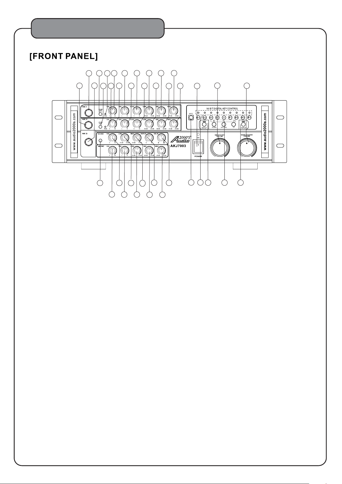
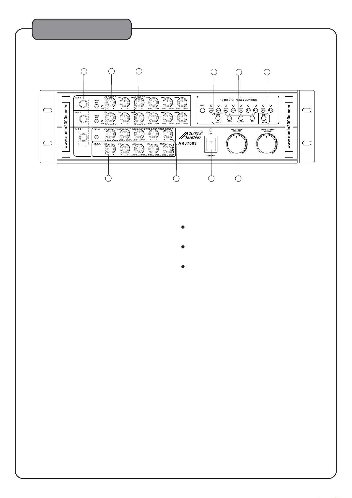
1. MIC1 - This is the microphone 1 .
6 7 8 9
16
23
17
24
29 30
18
Professional Karaoke
Mixing Amplifier
with Digital Echo &
Key Controls
25
19
27
15
22
28
unbalanced 1/4" input jack
33
0
34 35
36
31
38
32
37
2. -20dB GAIN - Pr ess this -20dB GAIN button to lower the MIC1 microphone audio level by 20 dB.
3. PEAK - This PEAK LED indicator is used to indicate that the MIC1 input audio level exceeds a preset limit.
4. VOL -
This VOL control knob is used to adjust the MIC1 audio level. Tu r n this knob clockwise to raise the
MIC1 audio level or turn this knob counter-clockwise to lower the MIC1 audio level.
5. BAL - This BAL control knob is used to allocate the portion of the MIC1
audio level to the left channel and
the right channel. When this knob is turned clockwise, the MIC1 audio level allocated to the right
channel is raised while the MIC1 audio level allocated to the left channel is lowered. When this
knob is turned
counter-clockwise, the MIC1 audio level allocated to the left channel is raised while
the MIC1 audio level allocated to the right channel is lowered.
6. ECHO - This ECHO control knob is used to control the MIC1 audio echo level (echo volume).
7. LOW - This LOW control knob
is used to control the MIC1 audio low frequency band centered at
around 150 Hz.
8. MID - This MID control knob is used to control the MIC1 audio mid frequency band centered at
around 1K Hz.
9. HIGH - This HIGH control knob is used to control
the MIC1 audio high frequency band centered at
around 6.5K Hz.
10. MIC2 - This is the microphone 2 u
11. MIC3 - 3The MIC2 and MIC3 input jacks share the
same control channel.
This is the microphone u.
12. -20dB GAIN - Pr ess this -20dB GAIN button to the MIC2 and MIC3
nbalanced 1/4" input jack
nbalanced 1/4" input jack
lower
.
microphone audio levels
by 20 dB.
13. PEAK - This PEAK LED indicator is used to indicate that the MIC2 and MIC3 input audio levels exceed
a preset limit.
14. VOL - This VOL control knob is used to adjust the MIC2 and MIC3 audio
levels. Turn this knob
clockwise to raise the MIC2 and MIC3 audio levels or turn this knob counter-clockwise to lower the
MIC2 and MIC3 audio levels.
15. BAL - This BAL control knob is used to allocate the portion of the MIC2 and MIC3
audio levels to the
left channel and the right channel. When this knob is turned clockwise, the MIC2 and MIC3 audio
levels allocated to the right channel are raised while the MIC2 and MIC3 audio levels allocated
to the left channel
are lowered. When this knob is turned counter-clockwise, the MIC2 and MIC3
audio levels allocated to the left channel are raised while the MIC2 and MIC3 audio levels allocated
to the right channel are lowered.
4
Page 7
DESCRIPTIONS AND FUNCTIONS
16. ECHO - This ECHO control knob is used to control the MIC2 and MIC3 audio echo levels (echo volumes).
17. LOW - This LO W control knob is used to control the MIC2 and MIC3 audio low frequency band centered
at around 150 Hz.
18. MID - This
at around 1K Hz.
19. HIGH - This HIGH control knob is used to control the MIC2 and MIC3 audio high frequency band
centered at around 6.5K Hz.
20.
ST/MO (Stereo/Mono) - Depress this button to enter the stereo echo output mode. Press to lift this button
again to enter the mono echo output mode.
21. ECHO VOL - This is the echo volume control knob.
22. LOW - This LO W control knob is used to
23. HIGH - This HIGH control knob is used to control the echo high frequency band.
24. REPEAT - This REPEAT control knob is used to adjust how many times the echo sound is to be repeated.
25. DELAY - This DELAY control knob is
26. MUSIC VOL - This is the music volume control knob.
27. BAL - This BAL control knob is used to allocate the portion of the music audio level to the left channel
and the right channel. When
channel is raised while the music audio level allocated to the left channel is lowered. When
this knob is turned counter-clockwise, the music audio level allocated to the left channel is
while the music audio level allocated to the right channel is lowered.
28. LOW - This LO W control knob is used to control the music audio low frequency band centered at
around 150 Hz.
29. MID - This MID control knob is used to
around 1K Hz.
30. HIGH - This HIGH control knob is used to control the music audio high frequency band centered
at around 6.5K Hz.
31. MIC MA STER VOLUME - This is the microphone master
controlled by the remote control unit.
32. MUSIC MA STER VOLUME - This is the music master volume control knob. This knob can be
controlled by the remote control unit.
33. POWER - Press this switch upward (to 1)
off the power.
34. REMOTE - The infrared control signal from the remote control unit is to be received through this sensor.
35. Key Control LED Indicators (b4 - #4) - These key control LED indicators
(from b4 to #4) is being applied to the music tone.
36. A INPUT - Press this button to select the music input A (VCD/CD).
37. B INPUT - Press this button to select the music input B (DVD).
38. Key Control Buttons
b: Lowers the music key one step (each step is ¼ note) each time this button is pressed
: Press this button to reset the music key to its natural key.
#: Raise s the music key one step
NOTE: The key will stay until it is changed further.
MID control knob is used to control the MIC2 and MIC3 audio mid frequency band centered
control the echo low frequency band.
used to adjust the time duration between each echo sound.
this knob is turned clockwise, the music audio level allocated to the right
raised
control the music audio mid frequency band centered at
volume control knob. This knob can be
to turn on the power. Press this switch downward (to 0) to turn
are used to show which key
( b, ,#)
(each step is ¼ note) each time this button is pressed
5
Page 8
DESCRIPTIONS AND FUNCTIONS
T6.3AL/250V
T4AL/250V
11
8
12
13
14
10
9
16
15
1
2 3
4
5
6
7
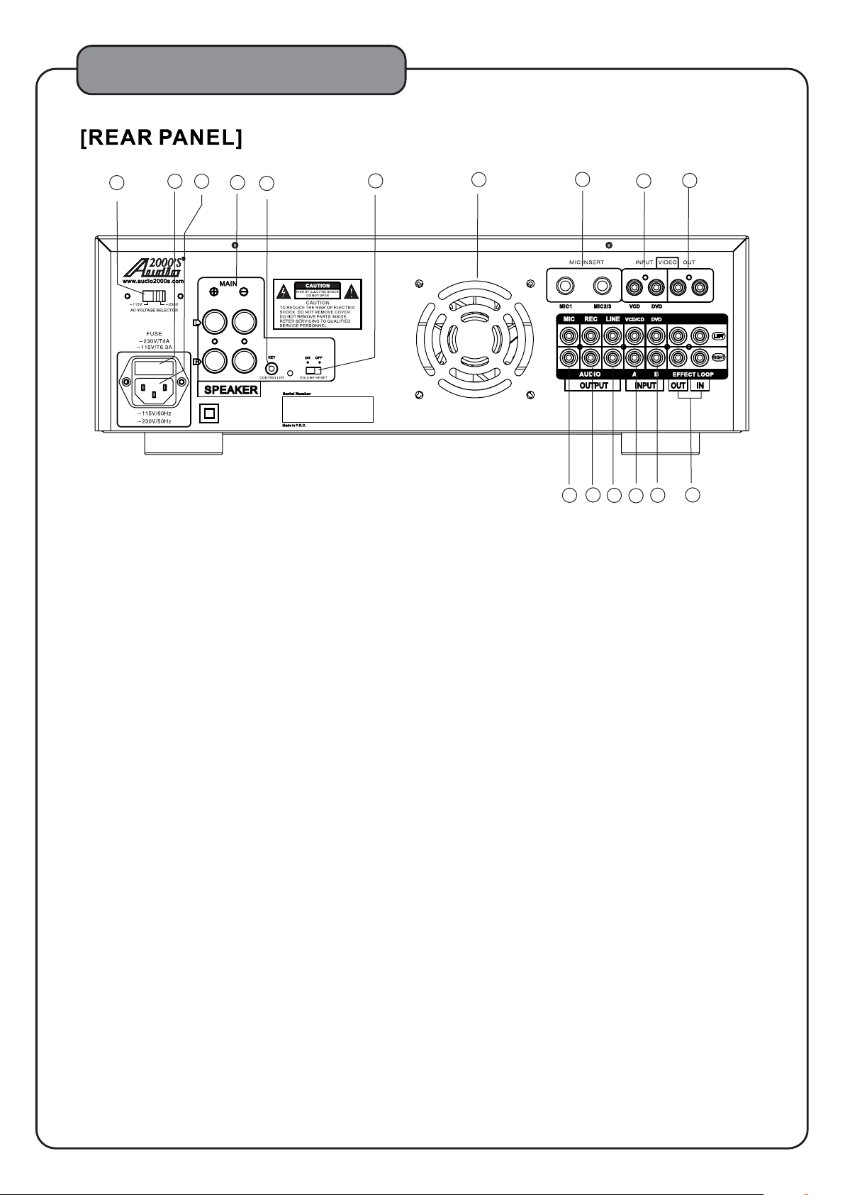
1. AC VOLTAGE SELECTOR - Check to make sure that the AC Voltage Selector switch is set to the proper
voltage for your area (120V/60Hz for the North America area) before plugging in the AC power cord
to the AC power outlet.
C AUTION: Unplug the
selector switch.
power cord from the power outlet before resetting the voltage
AC AC AC
2. FUSE - Please turn off the AC power and unplug the AC power cord before replacing the fuse. (ONLY
replacing with the same type and rating of new fuse.When the AC VOLTAGE SELECTOR is
new fuse should have the rating of T6.3AL/250V..When theAC VOLTAGE SELECTOR is set to 230V,
the new fuse should have the rating of T4AL/250V.)
set to 115V,the
3. ~115V/60Hz ~230V/50Hz AC Power Input Terminal
4. Speaker Output Terminals - Banana jacks are used as the speaker output terminals. The
overall
effective impedance of the speaker sets to each side (left or right side) of the speaker terminals needs to
be within the range of 4Ω To 16 . (Caution: If two sets of 8 speakers are connected to the same
speaker terminal, the effective
ΩΩ
impedance of these two speakers will be 4, just one half of its original
Ω
impedance.)
5. KEY CONTROLLER - This KEY CONTROLLER 3.5mm input jack is to be connected to some special
equipment, such as a key control microphone.
6. VOLUME RESET - When this VOLUME RESET
is switched to the OFF position, both the MIC MASTER
VOLU ME knob and the MUSIC MASTER VOLUM E knob will stay where they are after the main power is
turned on (after the power-on process). When this VOLUM E RESET is switched to the ON position, both
the MIC MASTER VOLUM E knob and the MUSIC MASTER VOLUME knob will be turned to the minimum
position automatically after the main power is turned on.
7. Cooling Fan
8. MIC INSERT - These are the TRS ¼” microphone effect inserts. The tip of the insert is used as the
audio
signal output (to the sound effect equipment), the ring of the insert is used as the audio signal input (from
the sound effect equipment), and the sleeve is used as the ground. The MIC1 is the microphone effect
insert for the MIC1 input.
The MIC2/3 is the microphone effect insert for the MIC2 and MIC3 inputs.
9. VIDEO INPUT - There are two video inputs, VCD and DVD.
10. VIDEO OUT - There are two independent video output jacks (each with its own driver).
11. MIC AUD IO OUTPUT - This audio output comprises the
microphone audio signal only.
6
Page 9
DESCRIPTIONS AND FUNCTIONS
12. REC AUDIO OUTPUT - This audio output is for the recording purpose and comprises a fixed
predetermined audio level.
13. LINE AUDIO OUTPUT - This is a line audio output with the audio level controllable by the
microphone and music volume controls.
14. INPUT A (VCD/CD)
15.
INPUT B (DVD)
16. EFFECT LOO P - The EFFECT LOOP allows the AKJ7003 user to add any sound effecter, such as an
equalizer, as a part of the music loop in the AKJ7003 unit. If an external sound effect is not used,
check to make sure that
The top U-shaped connector is to be connected from the white OUT jack to the white IN jack.
The bottom U-shaped connector is to be connected from the red OUT jack to the
sound effecter is to be placed in between the OUT jacks and the IN jacks, the U-shaped connectors
need to be removed from the unit and make sure that these two U-shaped connectors are taped to the
bottom of
effecter while the IN jacks are to be connected to the output ports of the sound effecter.
the unit for future use. The OUT jacks are to be connected to the input ports of the sound
two U-shaped connectors are connected from the OUT jacks to the IN jacks.
red IN jack. If a
7
Page 10
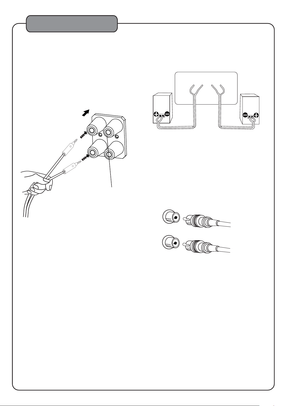
SPEAKER CONNECTIONS
Connection of Speaker Cables
Insert the banana connectors on the speaker
cables into the banana speaker jacks on the
AKJ7003 rear panel. Please refer to the
following pictures.
(+)Cord to (+) terminal
Red
Black
Right speaker
Left speaker
Connecting the RCA Cables
When connecting the RCA cables to the RCA jacks,
be sure to insert the red RCA plug into the red RCA
jack and the white or black RCA plug into the white
RCA jack.
(-) cord to (-) terminal
Left
White
Right
Red
Caution:
Tu rn off the AKJ7003 power when connecting the speaker cables to the speaker
output terminals on the AKJ7003. Before turning on the AKJ7003, make sure that any
metal part or copper wire of one speaker cable is NOT IN CONTACT with any metal
part or copper wire of another speaker cable.
White or Black
Red
8
Page 11
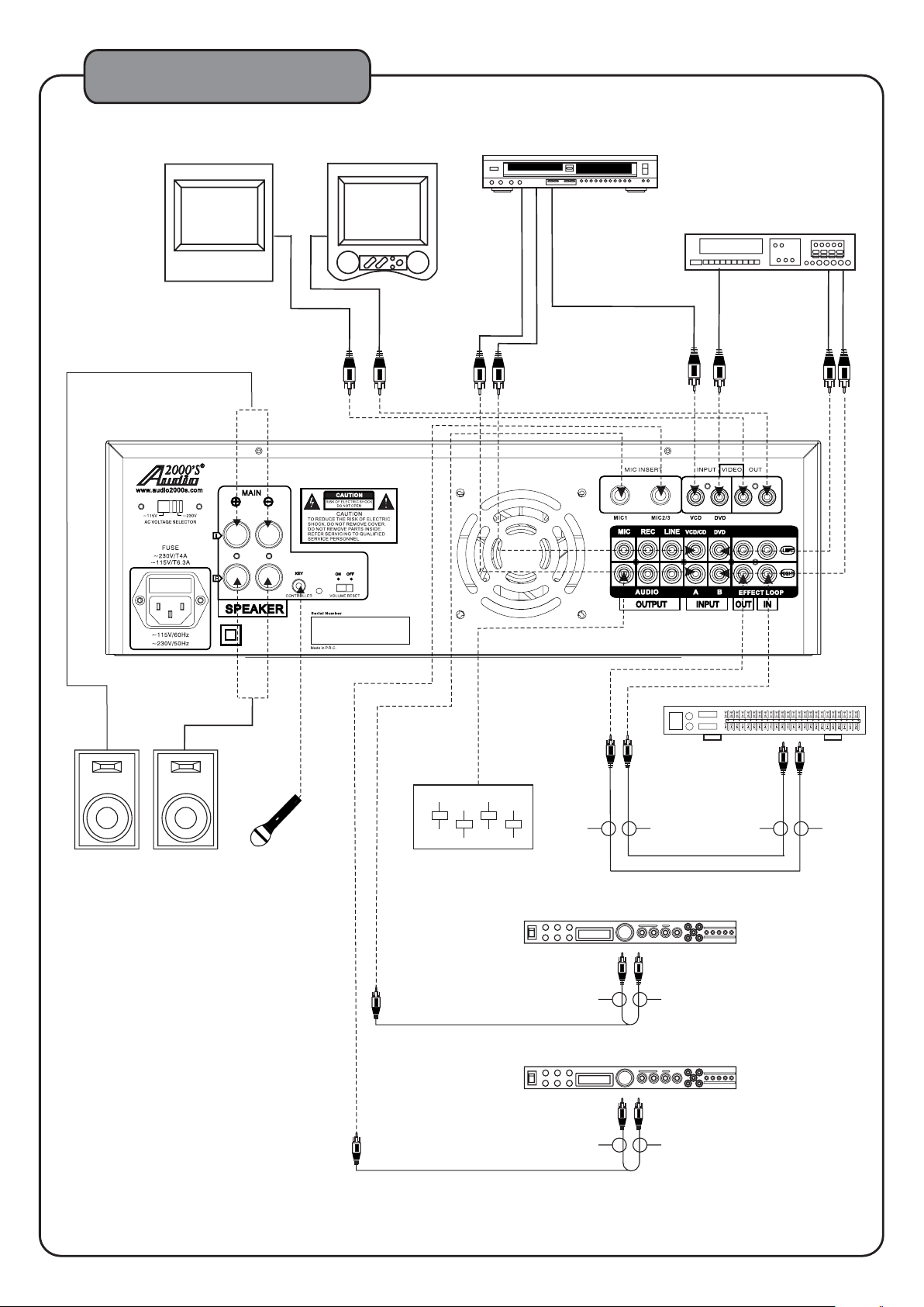
SYSTEM CONNECTIONS
Display Device
Display Device
VCD/CD
DVD
SPEAKER
RIGHT
SPEAKER
LEFT
Mic with Remot e
Key Control
Score Machine / Mixer / Amp.
OUT To To IN IN
Sound Effector
OUT To IN
To
Sound Effector
1
0
Equalizer
To To OUT
To OUT To IN
9
Page 12
GENERAL OPERATION
1
5
4
8
1. Connect a desired number of microphones to
the microphone inputs on the AKJ7003.
2. Turn on the power of the AKJ7003 and other
needed components.
(Press the POWER button on this unit to turn
on the power.)
Professional Karaoke
Mixing Amplifier
with Digital Echo &
Key Controls
7
3
0
2
9
6
3
Notes for Prop er Use of a Microphone
Hold
a microphone to have the top of its windscreen
1 to 2 inches away from your mouth.
To get the best pickup result, point the microphone
toward your mouth.
3. Select a karaoke
music source.
4. Adjust the music volume, balance, and tone.
5. Adjust each microphone volume by adjusting
the individual mcirophone VOLUME control knobs.
6. Adjust the desired relative volumes between
microphones and music by adjusting the
MIC MASTER VOLUM E control knob.
7. Adjust the
echo volume, tone, repeat, and delay.
8. Adjust the individual microphone echo volume by
adjusting the echo volume control knobs in the
MIC1 and MIC2/3 channels.
9. Press the KEY CONTROL button to set the
desired key.
To ensure a clear vocal output, do not block the lower
part of the microphone windscreen. Blocking
the lower
part of the microphone windscreen will disturb the
proper voice reproduction with an unclear bass which
tends to cause the feedback (howling) results.
10
Page 13
REMOTE CONTROL COMMANDER
MUSIC VOL
MIC
MASTER
VOLUME
b
#
LOW NATURAL HIGH
A
INPUT
B
M
U
S
ICVO
L
M
IC
M
R
ASTE
U
V
O
L
E
M
b
#
L
O
W
N
A
T
UR
A
L
HIG
H
A
I
U
T
NP
DESCRIPTIONS AND FUNCTIONS
A
1 2
.
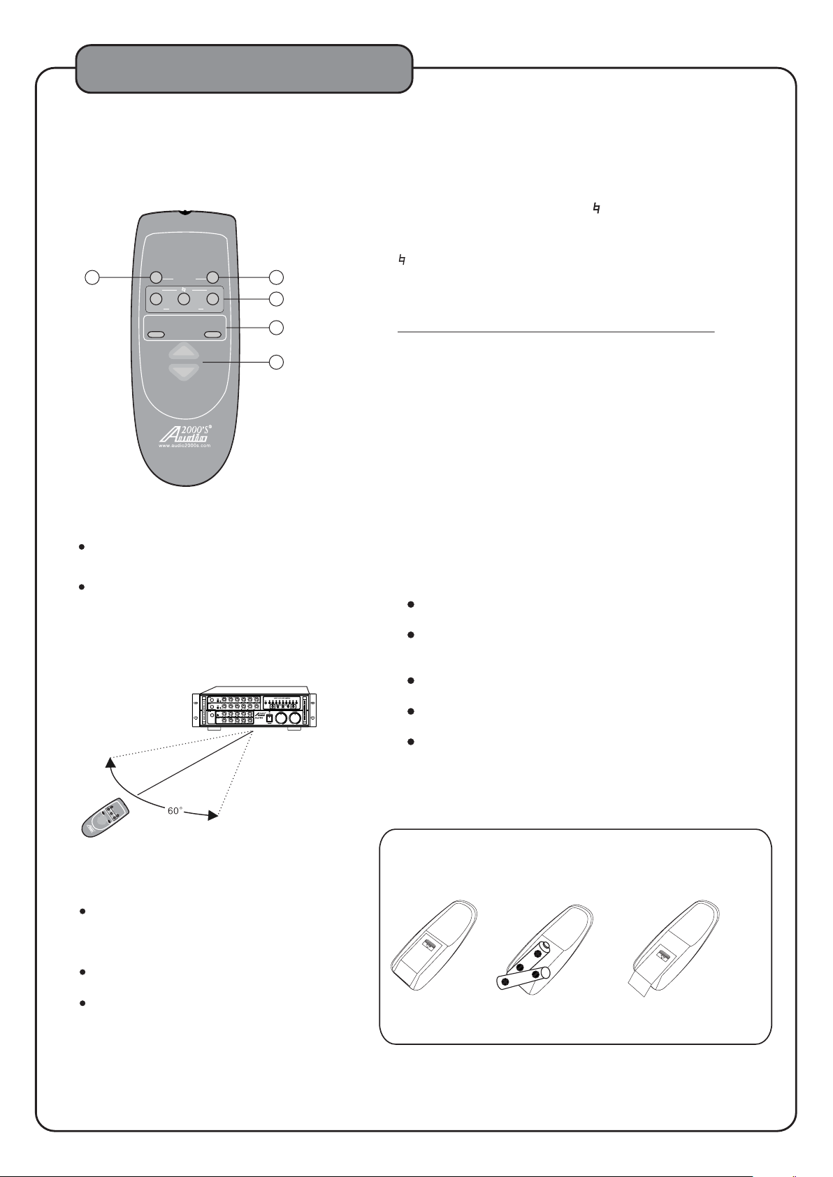
1 Operating range
LOW NATURAL HIGH
MIC
MASTER
VOLUME
MUSIC VOL
The operating range of the remote control comm ander is within a distance of about 16ft from the
remote control sensor on the amplifier.
Do not point the transmitter on the front edge of the
remote control commander to any
than the remote control sensor of the amplifier or
leave an obstacle between the remote control
and he amplifier.
commander t
Doing these may make remote control impossibe.
t 1
b
INPUT
+
-
ACC7003-01
f Aou 6t
B
+-
3
4
5
other direction
Professional Karao ke
0
Mixing Amplifier
with Digital Ech o &
Key Controls
1. INPUT A - Press this button to select the music source
from input A.
2. INPUT - Pre ss this button to select the music source
from input .
B
B
3. KEY CONTROL BUTTONS ( b, ,#)
b: Lowers the music key one step (each step is ¼ note)
each time this button is pressed
: Press this button to reset the music key to its
natural key.
#: Raise s the music key one step (each step is ¼ note)
each time this button is pressed
NOTE:
The key will stay until it is changed further.
4. MIC MA STER VOLUME - These are the microphone master
volume control buttons. Press the "+" button to raise the
microphone master volume. Press the "-" button to lower the
microphone master volume.
5. MUSIC MA STER VOLUME - These are the music master
volume control buttons. Press the "+" button to raise the
music master volume. Press the "-" button to lower the
music master volume.
3.Battery handling precautions
Battery may explode or its fluid may leak if the batteries
are handled in a wrong way. Take care of the following
when handling the batteries.
Insert batteries with correct positive (+) and
negative(-) polarities as indicated on the set.
Even batteries with the same shape sometimes have
different voltages. Do not mix batteries with different
types together.
Do not use new and old batteries together. When
replacing batteries, be sure to replace both of them.
Do not heat, open or short-circuit a battery or dispose
of it in fire.
Some batteries are rechargeable and some are not.
Check the indication on each battery well.
A
L
O
I
N
W
P
N
U
-
MR
T
A
T
B B
UR
V
M
ASTE
A
OL
IC
L
#
U
H
M
M
IG
+
U
E
H
SIC
+
-
V
O
L
A
CC
700
3
-0
1
Remote control
unit
2.Loading batteries
The battery life is about 1 year under
normal use, but it is recommended to
replace the batteries when their power
seems to be weak.
This remote control commander accepts
two "AAA" batteries.
Remove the batteries if
commander is not to be used for a long
period of time.
the remote control
1.Push the tab
and remove the
battery cover.
11
2.Insert batteries with
correct positive(+)and
negative(-)polarities.
"AAA" batteries X 2
3.Push the cover
close until it clicks.
Page 14
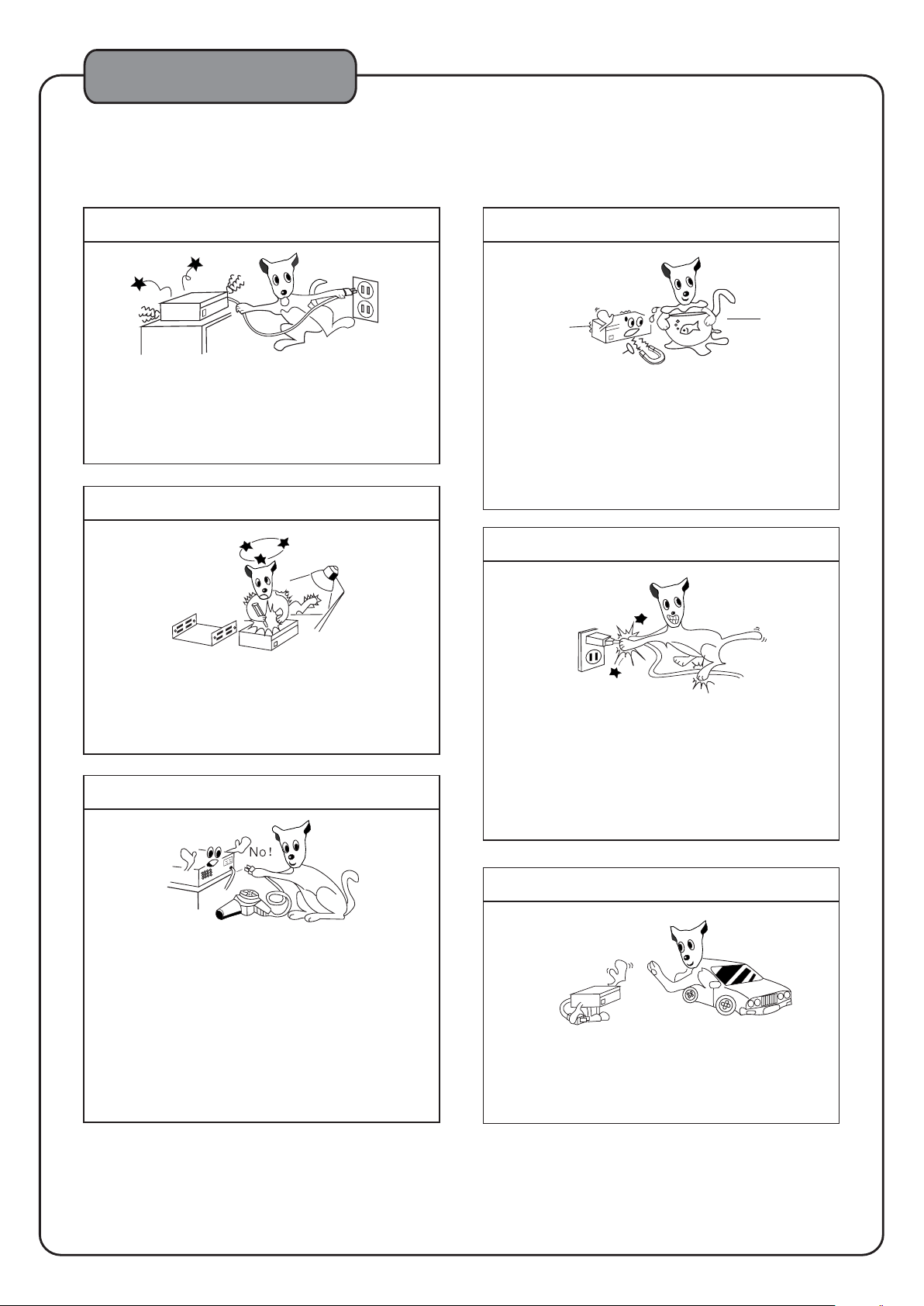
SAFETY PREC AUTIONS
In case of abnormality
In case an abnormal noise or smell is generated from
the unit during use, immediately switch the power off,
unplug the power cord from the power outlet,and
consult your dealer or an authorized service center
for a check-up.
Do not open the unit
High-voltage components are used inside the unit.
Do not open the cabinet to check or modify
for this will cause the danger of electric shock.
Performance degradation or malfunction due to the
user modification will not be covered by the warranty.
the unit,
Do not exceed the maximum power capacity
Keep away from water and foreign objects
Do not insert or drop metallic objects,such as a
hairpin,nail and coin,or flammable objects,such as
paper and matches,through the ventilation holes or
other openings on the unit,for this will cause
malfunction or hazard of fire and electric shock. In
case water or a foreign object enters inside the unit,
consult an authorized service
for a check-up.
center or your dealer
Do not damage the power cord
Hold the power plug when plugging or unplugging
the power cord. Do not pull the cord or touch it with
wet hands,for this may cause short-circuit or electric
hazard. Do not leave the power cord under this unit,
or under furniture,or between objects.Also do not tie
power cord with another cord,make a knot on the
the
power cord,or leave it in a place where people walk
frequently.
The components equipped with the rear panel AC
OUTLETS accept the connection of other stereo
system components.
However,do not connect components the total
power consumption of which
capacity marked on the panel, for this may cause
malfunction or fire hazard.Also note that
components in which large current flows when the
power is switched on, such as a TV, cannot be
connected to such an AC outlet unless it has been
designed to accept the connection of a TV
exceed the power
set.
When the unit is not to be used for a long period
When you will be away from home for a long period
of time,for example before going on a trip,set the
power switch to off and unplug the power plug from
the power outlet
hazard due to unexpected accidents with the unit
for safety. This will prevent fire
12
Page 15
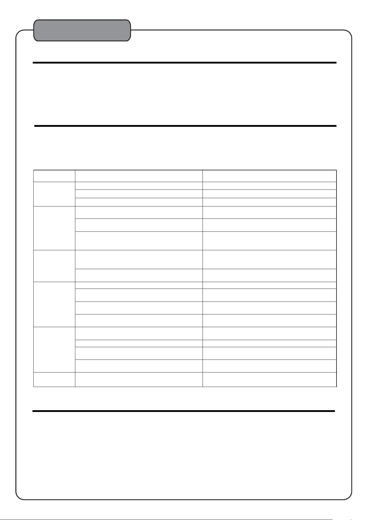
TROUBLESHOOTING
MAINTENANCE
When the set gets dirty, wipe with a soft, dry cloth. If
the set is extremely dirty, soak a soft cloth in a 5 to 6%
solution of dishwashing detergent to water,wring it
tightly, wipe the dirt away, and finally wipe the set with
a dry cloth.
Never use alcohol, thinner, benzine, insecticide
volatile agents, as they may damage the surface paint
or gloss of the set.
Also do not wipe the set with a chemical cloth or leave
it on the set for a long period, as the surface finish may
be damaged or the paint may be stripped off.
TROUBLESHOOTING
Should problems
simple operation mistakes or the like. On the basis of checks, please consult your dealer.
the following checks, you will be able to rectify a
number of problems yourself without difficulty.
PROBLEM
No power
One side
no sound
Distorted
sound
No sound
No microphone sound
Humming
noise
occur, they are, in many cases, due to If the problem cannot be remedied after the following
POSSIBLE CAUSES
Power is off.
AC power cord is unplugged. Plug the AC power cord to an AC power outlet (120V).
The fuse inside the transformer is open. Send the mixing amplifier to an authorized service center.
One bad RCA cable or one poor RCA contact.
One bad speaker cable or one poor speaker
connector contact.
One U-shaped connector is not inserted into the
music effect jacks or one U-shaped connector is not
properly inserted.
The electrical signal from the output of the player to
the mixing amplifier is over the limit of the input of
the mixing amplifier.
Incorrect AC Voltage
to a 240V outlet or to an unstable 120V outlet).
Incorrect input selection. Make sure the input source selection button is set correctly.
Music volume control knob is turned all the way down
(zero sound output).
Both U-shaped connectors are not inserted into the
music effect jacks or not
Bad cable or poor contact.
The microphone cable is not plugged into the
microphone input jack properly.
The switch on the microphone is set to “OFF”. Set the switch on the microphone to “ON” .
The corresponding INDIVIDUAL MIC VOLUME control or the
MASTER MIC VOLUME control is in the minimum position.
A condenser microphone is used.
Grounding problems between two adjacent equipments.
(The AC power cord is plugged
properly inserted.
Turn on the mixing amplifier.
Make sure that all RCA cables are not damaged and all
RCA contact points are proper.
Make sure that all speaker cables are not damaged and
all speaker cable contact points are proper.
Make sure all the U-sha p e d connectors are properly
inserted.
Turn down the master volume control of the player and
turn up the volume control of the mixing amplifier to
maintain the same sound level.
Make sure the AC power cord is plugged to an AC power
outlet with a correct and stable AC voltage.
Turn the music volume knob to a position that the
sound level is desired.
Make sure all the U-shaped connectors are properly
inserted.
Make sure that all cables are not damaged and all
contact points are proper.
Make sure the microphone cable is plugged into the
microphone jack properly.
Adjust the volume control.
Change th e condenser microphone to a dynamic microphone or a condenser microphone accepting battery power.
Try to use an isolator to remove the grounding problems.
SOLUTIONS
or other
ETIQUETTE OF SOUND
The karaoke performance you enjoy may be disturbing noise to others.When performing karaoke,be sure to be
considerate of your neighbors.
The volume of karaoke is at your command. Remember that even small sounds transmit very well in the quiet night.
Be specially careful in karaoke
leakages to the neighbors.Avoid noise pollution to protect the comfortable living environment of those around you.
performance at night.it is recommended to close the windows to avoid sound
13
Page 16
SPECIFICATIONS
Amplifier
Maximum Output(1KHz,8Ω ,THD 1%)---60W+60W
Total Harmonic Distortion ............................ 0.03%
(1KHz,50W,8Ω)
Input Jacks(Sensitivity/Impedance)
MIC(1 ,2/3) ........................................ <10mV
DVD,VCD............. ...................... 350mV/23kΩ
Frequency Responses
MIC Frequency Sound................. 100Hz to 25kHz
MUSIC ......................... 10Hz to 20kHz,+3/-3dB
To n e Control Characteristics
Music
BASS ............. +15/-15dB(100Hz)
MID ................ +12/-12dB(1KHz)
TREBLE ......... +15/-15dB(6.3KHz)
Microphone BASS ..............+15/-15dB(100Hz)
MID ................. +15/-15dB(2KHz)
TREBLE ........... +15/-15dB(10kHz)
Key Control Range ....................................... 9 steps
Video Input Jacks
(Sensitivity/Input Impedance) .............. 1Vp-p/75Ω
Video Output Jacks
(Output level/Output Impedance) ........
1Vp-p/75Ω
Effect Loop Jacks
(Output level/Input Sensitivity)......500mVp-p/4.7kΩ
MIC Output.......................................1Vp-p/4.7kΩ
REC Output........................................1Vp -p/4.7kΩ
LINE Output.......................................2Vp-p/4.7kΩ
Pow er Supply, etc.
Supply Voltage .............. AC 115V/230V 60Hz/50Hz
Power Consumption .....................................400W
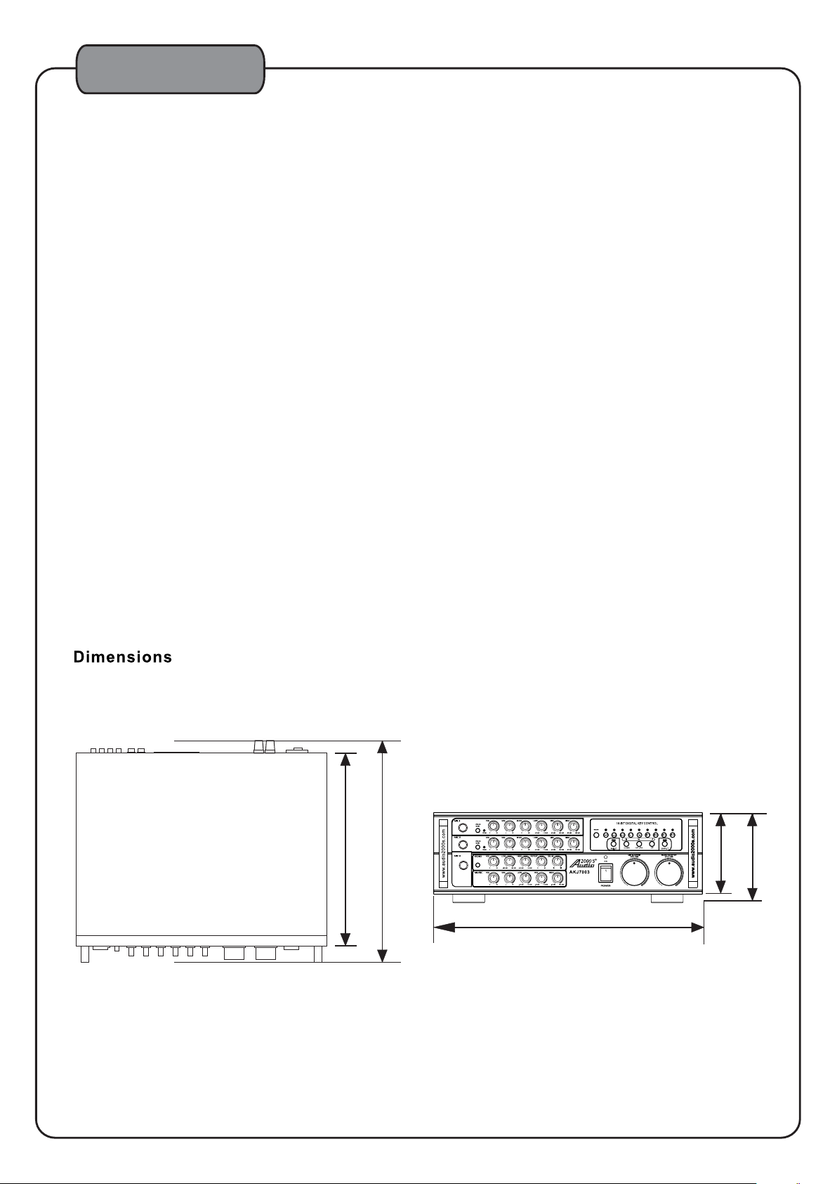
Dimensions(W X H X D)................16.5'' X 5.4'' X 14.6''
Weight.................................................... 14.3
lbs
Accessories
Remot e Control Unit ........................................... 1
Rack Mount........................................................ 2
Power Cord....................................................... .1
Owner'
s Manual ................................................ 1
Warranty Card.................................................... 1
12.7''
14.6''
14
Profession al Karaoke
Mixing Am plifier
with Digital Echo &
Key Cont rols
16.5''
5.0''
5.4''
0
Page 17

SERVICE INFORMATION
SERVICE INFORMATION
SHIPPING DAMAGE
If the shipping carton is found to be damaged, notify the delivery company immediately.
Save the damaged carton as evidence for the delivery company to inspect. It is the
responsibility of the consignee to file a claim with the delivery company for any damaged
that occurs during shipping. In
the unit is damaged or defective, call Audio2000'S at 805-523-2759.
the case that the shipping carton is in good condition but
®
FACTORY SERVICE
If the equipment needs factory service, call Audio2000'S at 805-523-2759 for a Return
Authorization number (RA number) and the address of the authorized service
representatives. Insure and ship the product, prepaid, in its original carton along with
proof of purchase in the form of a bill of sale or receipted
Please clearly write the RA number on the shipping carton. Also enclose a note
describing the problem along with any other helpful information such as where and
how the unit was used.
®
invoice to the above address.
LIMITED WARRANTY
H&F Technologies, Incorporated (H&F) hereby warrants that Audio2000'S products will be
free from defects in material and workmanship for a period of 1 (one) year from date of
purchase. At its option, H&F will repair or replace the defective product and promptly
return it to you.
The Limited Warranty
subject to alteration, misuse, neglect, accident or improper installation. In addition,
any service not performed by H&F or an authorized service center will terminate terms
of this warranty. Normal wear and tear of this product will not be
implied warranty.
No liability will be accepted for damages/loss directly caused from the use of
this product.
H&F's liability shall be limited to the repair/replacement of this product if found
to be defective.
will not cover any item that has been, in H&F's estimation,
covered by this or any
®
© 2010 H & F Technologies, Incorporated (website: www.audio2000s.com)
15
 Loading...