

Page 1
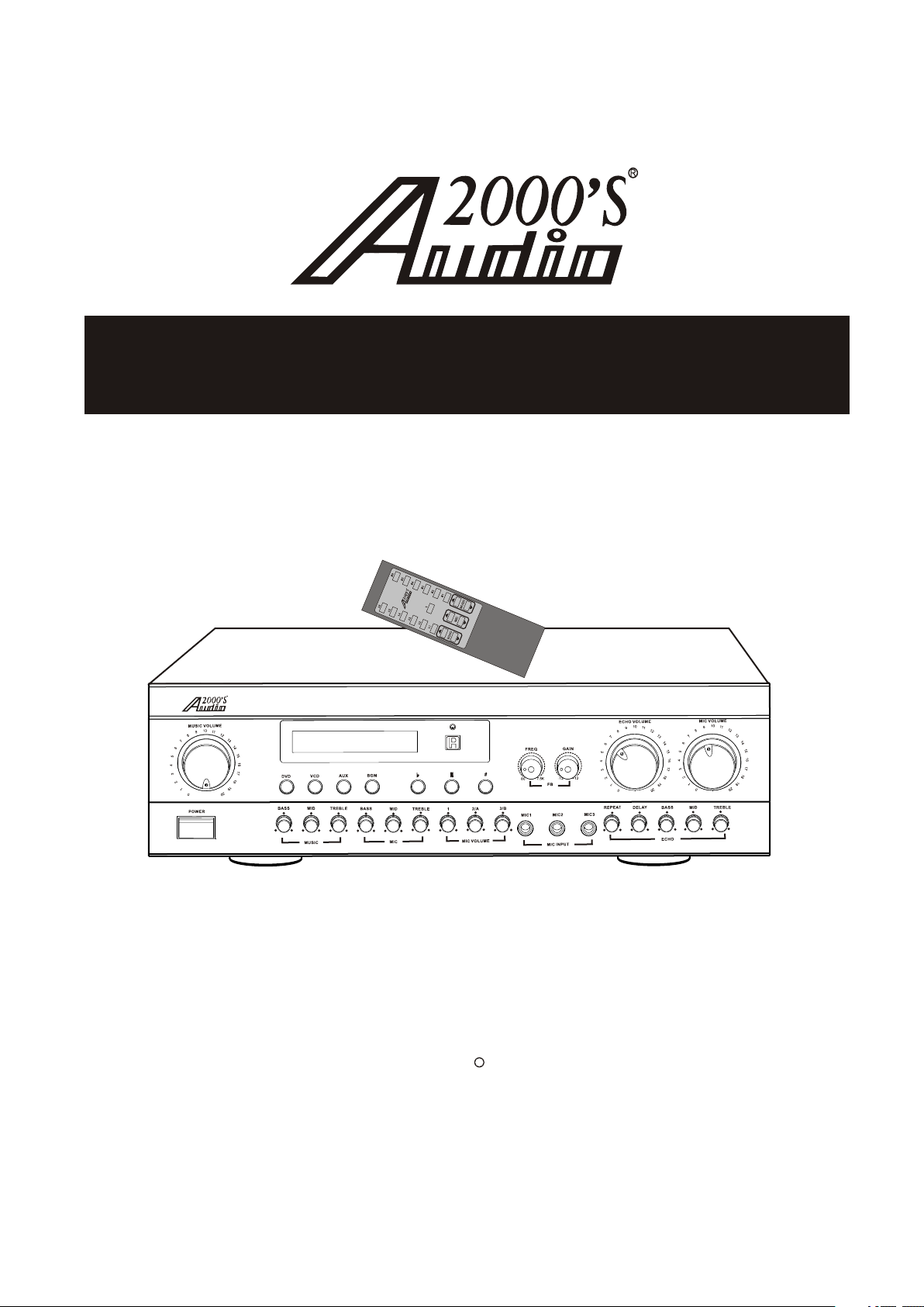
PROF. KARAOKE MIXER WITH DIGITAL ECHO, KEY,
AND FEEDBACK CONTROLS
AKJ7404
OWNER’S MANUAL
1
3
4 -
C7 0
C
A
S
L
RO
T
ON
C
K
C
B
D
EE
D F
N
A
EY,
K
HO,
C
TAL E
GI
I
TH D
IXER W I
E M
K
O
A
A
L
NA
I
SS
ROFE
P
04
74
J O K R A
AK
AUTO
Thank you for purchasing the Audio2000'S professional karaoke mixer with digital
R
echo, key, and feedback controls! To achieve maximum performance from your new
unit, please read this manual thoroughly, and retain it for future reference. For more
information, please visit our website (www.audio2000s.com).
Page 2
TABLE CONTENTS:
WARNING AND SAFETY INSTRUCTION.......................................
FEATURES ................................................................................
HANDLING PRECAUTIONS ........................................................
BEFORE CONNECTIONS ............................................................
DESCRIPTIONS AND FUNCTIONS
● FRONT PANEL ......................................................................
● REAR PANEL .........................................................................
SYSTEM CONNECTIONS ...........................................................
PRINCIPLE OF AUDIO VIDEO SWITCHOVER ..........................
GENERAL OPERATION .............................................................
REMOTE CONTROL UNIT .........................................................
SAFETY PRECAUTIONS ............................................................
MAINTENANCE .......................................................................
TROUBLESHOOTING ...............................................................
ETIQUETTE OF SOUND ............................................................
SPECIFIC ATIONS .....................................................................
1-2
3
3
3
4-5
6-7
8
9
10
11
12
13
13
13
14
IMPORTANT
For your protection,please read these instructions completely, and keep
this manual for future reference.
Carefully observe and comply with all warnings,cautions,and instructions
placed on the equipment or described in the operations instructions to
guard against injury.
Page 3
CAUTION:TO REDUCE THE RISK OF ELECTRIC SHOCK,
REFER SERVICING TO QUALIFIED SERVICE PERSONNEL
WARNING
DO NOT REMOVE COVER (OR BACK)
NO USER-SERVICEABLE PARTS INSIDE
The lightning flash with arrowhead symbol,within
an equilateral triangle,is intended to alert the user
to the presence of uninsulated "dangerous voltage"
within the product's enclosure that may be of sufficient magnitude to constitute a risk of electric shock
to persons.
The exclamation point within an equilateral triangle
is intended to alert the user to the presence of
important operating and maintenance (servicing)
instructions in the literature accompanying the
appliance
TO REDUCE THE RISK OF FIRE OR ELECTRIC SHOCK,
DO NOT EXPOSE THIS APPLIANCE TO RAIN OR MOIST URE
CAUTION:TO PREVENT ELECTRIC SHOCK,MATCH WIDE
BL ADE OF PLUG TO WIDE SLOT, FULLY INSERT.
ATTENTION:POUR EVlTER LES CHOCS ELECTRIQUES
INTRODUlRE L A L AME L A PLUS LARGE DE L A FICHE DANS
L A BORNE CORRESPON-DANTE DE LA PRISE ET POUSSER
JUSQU'AU FOND.
Page 4
SAFETY INSTRUCTIONS
READ BEFORE OPER ATING EQU IPMENT
This product was designed and manufactured to meet
strict quality and safety standards. There are, however,
some installation and operation precautions which
you should be particularly aware of.
1) Rea d Ins tructions--All the safety and operating
instructions should be read before the appliance
is operated.
2) Ret ain I nstructions--The safety and operating ins tructions should be retained for future reference.
3) Heed Warnings --All warnings on the appl ian ce
and in the operating instructions should be
adhered to.
4) Follow Instructions--All operating and use instr uctions should be followed.
5) Water and Moisture --The appliance should not
be used near water -- for example, near a bathtub,
wash-bowl.Kitchen sink, laundry tub, in a wet
basement, or near a swimming pool, etc.
6) Carts and Stands--The appliance should be used
only with a cart or stand that is recommended by
the manufacturer.
11) Power Sources--The appliance should be con nected to a power supply only of the type des cribed in the operating instructions or as mar ked on the appliance.
12) Grounding or Polarization-The precautions that
should be taken so that the grounding or pola rization means of an appliance is not defeated.
13) Power- Cord Pr ote cti on- Power- supply cords sh ould be routed so that they are not likely to be
walked on or pinched by items placed upon or
against them,paying particular attention to co rds at plugs,convenience receptacles,and the
point where they exit from the appliance.
14) Cleaning-The applia nce s hou ld be c lea ned o n ly as recommended by the manufacturer.
15) Power Lines-An outdoor anten na sh oul d be lo cated away from power lines.
16) Nonuse Periods-The power cord of the applia nce should be unplugged from the outlet when
left unused for a long period of time.
7) An appliance and cart combination should be
moved with care. Quick stops, excessive force,
and uneven surfaces may cause the appliance
and cart combination to overturn.
8) Wall or Ceiling Mounting--Th e app liance should
be mounted to a wall or ceiling only as recom mended by the manufacturer
9.Ventilation--The appliance should be situated so
that its location or position does not interfere with
its proper ventilation. For example, the appliance
should not be situated on a bed, sofa,rug,or similar
surface that may block the ventilation openings;or,
placed in a built-i n ins tal lat ion ,su ch as a b ook cas e
or cabinet that may impede the flow of air through
the ventilation openings.
10) Heat- -The appliance should be situated away
from heat sources such as radiators,heat
registers,stoves,or other appliances(including
amplifiers)that produce heat.
17) Object and liquid Entry-Care should be taken
so that objects do not fall and liquids are not
spilled into the enclosure through openings.
18) Damage Req uir ing Service-The appliance sho uld be serviced by qualified service personnel
when;
A.The power- supply cord or the plug has been
damaged;or
B.Objects have fallen,or liquid has spilled into
the appliance;or
C.The appliance has been exposed to rain;or
D.The appliance does not appear to operate
normally or exhibits a marked change in
performance;or
E.The appliance has been dropped,or the
enclosure damaged.
19) Servicing-The user shoul d not a tte mpt t o ser vic e
the appliance beyond that described in the op erating instructions. AII other servicing should
be referred to qualified service personnel.
Page 5
FEATURES
FEATURES
1. High Quality Dual Digital Echo Effects with Individual Treble/Mid/Bass Controls.
2. Five Microphone Inputs (Three at the Front Panel, Two at the Rear Panel).
3. Three Individual Microphone Volume Controls (1, 2/ A, an d 3/B ).
4. Master Microphone Volume/Treble/Mid/Bass Controls.
5. Master Music Volume/Treble/Mid/Bass Controls.
6. Feedback Frequency and Gain Controls.
7. Four Audio Inputs with Automatic or Manual Audio Channel Selections.
8. 13-Step Digital Key Changer.
9. Digital Echo Volume/Repeat/Delay/Bass/Mid/Treble Controls.
10. Re mote Control.
11. Mono Microphone Effect Input/Output.
12. Stereo Music Effect Inputs/Outputs.
13. Four Video Inputs and Four Video Outputs.
14. Audio Input Level Adjustment.
HANDLING PRECAUTIONS
Do not install the unit in following places:
In a place which is exposed to direct sunlight or near
a source of heat such as a radiator.
In a place where the heat cannot escape due to poor
ventilation, or where it is very humid or dusty.
In an unstable place with excessive vibrations or
sloping.
In a place which may be exposed to rain, such as
near a window.
In a place which may be exposed to soot, vapor or
heat, such as near a cooking stove.
BEFORE CONNECTIONS
Connection precautions
Be sure to switch off the powers of the related
equipment before making any connection.
The "White" input/output jacks of the mixer are
designed for the Left channel, while the "Red' jacks
are for the Right channel. Be sure to connect the
cords without mistaking the correspondences of the
Left a nd Ri ght channels.
Insert the plugs of the connection cords securely into
the jacks. If the connection is incomplete, sound may
not be produced or noise may be generated.
Power consumption of AC power outlets
Be careful that the total power consumption does not
exceed the wattage marked on the rear panel. Do not
connect other appliances than the system
components to the power outlets of this unit.
Do not connect a TV set to this unit, even if the power
consumption value marked on a TV set is below the
permissible limit of this unit. A larger current than the
permissible value may flow when the TV power is
turned on.
When unplugging the power cord from the power
outlet, be sure to grasp the plastic molding of the
plug and pull.
Page 6
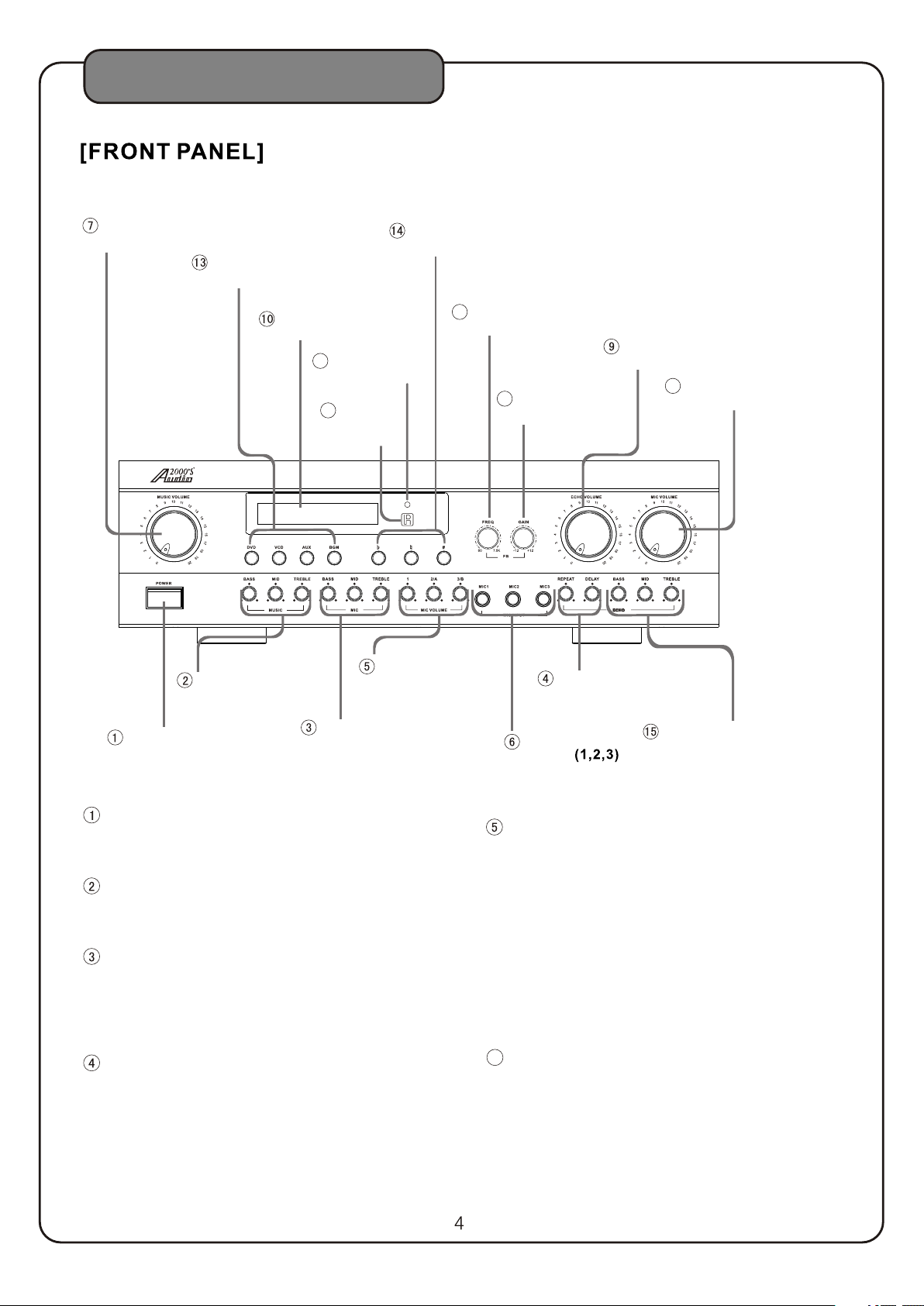
DESCRIPTIONS AND FUNCTIONS
MUSI C VOLU ME
CONT ROL
INPU T SELECTI ON
BUTT ONS
VFD DISPL AY
PANEL
16
AUTO/M AN UA L
INDI C ATOR
17
REMO TE
CONT ROL
SENS OR
AKJ 7404 PRO FESSI ONAL KA RAOKE M IXER WI TH DIGI TAL ECHO, KEY,AND F EEDBA CK CONT ROLS
AUTO
INDI VIDUAL
MUSI C TONE
CONT ROLS
MICR OPHONE
VOLUME C ON TROLS
KEY CO NTROL
BUTT ONS
FB CON TR OL FREQ
11
ADJU STMENT
FB CON TR OL GAIN
12
ADJU STMENT
ECHO D EL AY/
REPE AT CO NT ROLS
ECHO V OL UM E
CONT ROL
8
MA STE R MI C
VOLUME C ON TROL
POWE R
MICR OPHONE TO NE
CONT ROLS
POWER
Press this button to turn the power on. Press this
button again to turn the power off.
MUSIC TONE (BASS /MI D/T REB LE) C ONT ROLS
These controls are used to boost or cut the low,
mid and high frequency responses.
MICROPHONE TONE (BA SS/ MID /TR EBL E)
CONTROLS
These controls are used to boost or cut the low,
mid and high frequency responses of
microphones 1, 2, 3, A, and B.
ECHO DEL AY/REPEAT CONTROLS
Adjust the parameters of the echo effect with these
controls as desired.
DELAY Control: Adjust the time duration between
each echo sound.
REPEAT Control: Adjust how many times the echo
sound is to be repeated.
MI C INP UT
JA CK S
ECHO T ONE BASS/MID /
TREB LE CONTRO LS
INDIVIDUAL MICROPHONE VOLUME
CONTROLS (1, 2/A, 3/ B)
1: This control knob adjusts the microphone input
level from the MIC INPUT 1 jack (front panel).
2/A: This control knob adjusts the microphone
input level from the MIC INPUT 2 jack (front
panel) and the MIC INPUT A jack (rear panel).
3/B: This control knob adjusts the microphone
input level from the MIC INPUT 3 jack (front
panel) and the MIC INPUT B jack (rear panel).
Normally, set these control knobs to the center
positions.
MICROPHONE INPUT JACKS (1, 2 ,3)
6
These jacks are for connecting microphones.
Page 7
DESCRIPTIONS AND FUNCTIONS
7
MUSIC VOLUME C ONTROL
This control knob allows the user to adjust the
volume of the music output.
8
MA S TER M ICR OPH ONE V OLUME CONTROL
This control knob adjusts the overall volume of
all microphones.
ECHO VOLU ME CO NTROL
9
This control knob adjusts the volume of the
microphone echo effect.
VFD DISPL AY PANEL
10
This panel display all input information and
key control information.
11
FEEDBACK CONTROL FREQUEN CY
ADJUSTMENT (FREQ)
When the use of microphones causes feedback
(howling) results, turning the frequency
adjustment knob to match the feedback control
frequency to the howling frequency. The
feedback control frequency range is from
80Hz to 7.5KHz.
14
KEY CONTROL BUTTONS
b : Lowe rs th e music key one step (each step is
1/4 note) each time this button is pressed.
: Rese ts th e mus ic key to its natural key.
# : Raises the music key one step (each step is 1/4
note) each time this button is pressed.
Note:The key will stay until it is changed further.
ECHO TONE (BA SS/ MID /TR EBL E) CO NTR OLS
15
These controls are used to boost or cut the low, mid
and high frequency responses of the echo sound.
16
AUTO / M ANUAL INDIC ATOR
This is to indicate the status of the AUTO ON OFF
switch on the rear panel. When the AUTO ON OFF
switch is set to ON, the LED indicator will be turned on.
When the AU TO ON OFF switch is set to OFF, th e
LED indicator will be turned off.
17
REMOTE CO NTR OL SENS OR
The infrared control signal from the remote control
commander is to be received through this sensor.
12
FEEDBACK CONTROL GAIN ADJU STM ENT
(GAIN)
When the use of microphones causes feedback
(howling) results, turning the gain adjustment
knob to adjust the amplitude (gain) of the
howling frequency. The feedback control gain
can be adjusted between -12dB and +12dB.
13
INPUT SELECTION BUTTO NS
These buttons can be manually set only
when the AU TO ON OFF switch on the
rear panel is set to OFF.
When used, press any of these buttons to
select the desired music input source.
Page 8
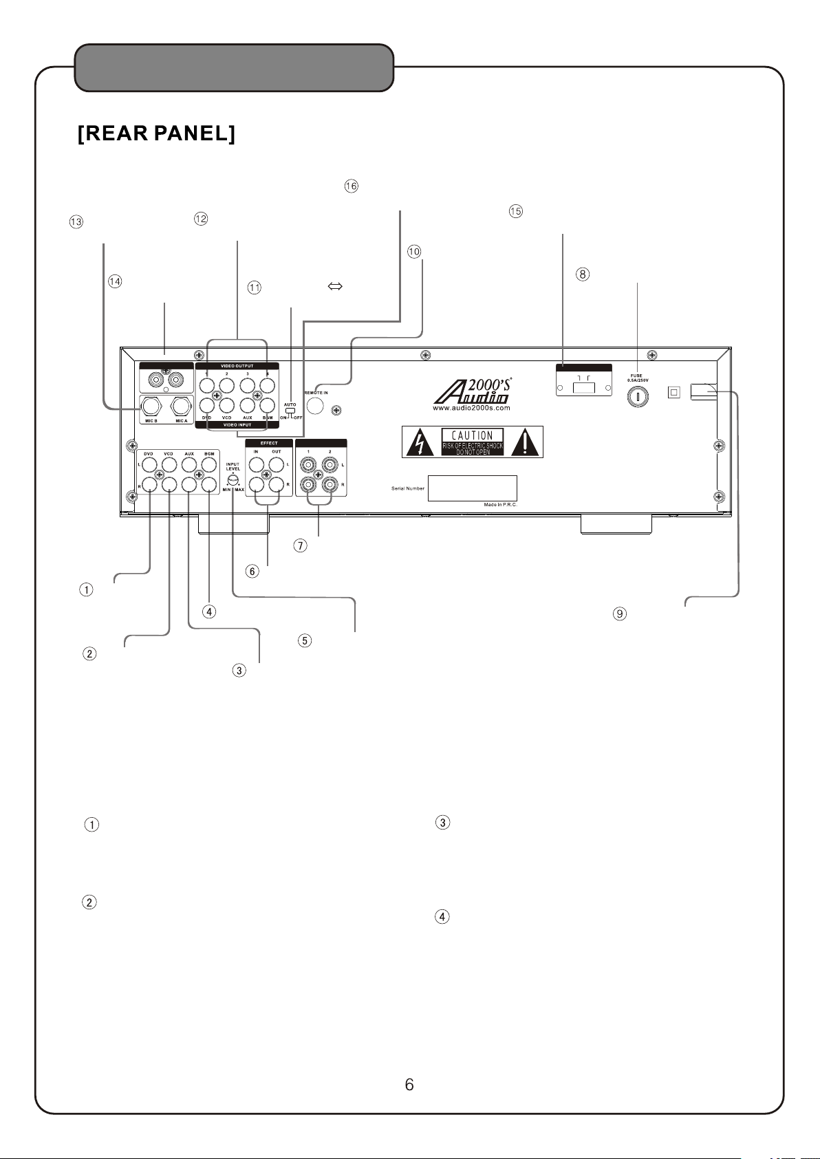
DESCRIPTIONS AND FUNCTIONS
VIDEO INP UT JACKS
(DVD,VC D,AUX ,BGM)
MIC INPUT
JACKS(A ,B)
MIC EF FE CT INPUT/
OUTP UT J ACKS
VIDEO OUT PUT
JACKS(1 ,2,3,4)
AUTO O N OFF
SWITCH
VOLTAGE
SELECTO R
REMOTE IN
FUSE TERM INAL
DVD
VCD
MIC EFF ECT
IN
Voltag e Selec tor
230V 115V230V 115V
OUT
PRE-O UT
AC IN
115V/2 30V
50Hz/ 60Hz
PRE-OUT
MUSIC EFF ECT INPUT/
OUTPUT JA CKS
BGM
AC POWER CO RD
INPUT LEV EL
AUX
DVD
Connect the output jacks of the DVD player
to these jacks.
VCD
Connect the output jacks of the VCD player
to these jacks.
AUX
Connect the audio output of any auxiliary
component, such as a cable broadcasting
tuner, to these jacks.
BGM
Connect the output jacks of the BGM
(background music) player to these jacks.
Page 9
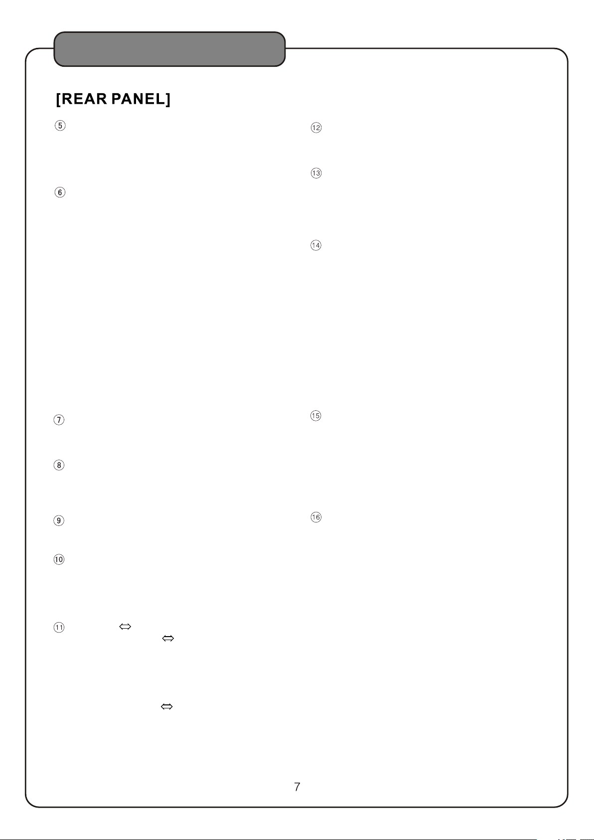
DESCRIPTIONS AND FUNCTIONS
INPUT LEVEL
Turn this input level control to adjust the input
level. Turn the input level control counterclockwise to reduce the input level. Turn the input
level control clockwise to raise the input level.
MUSIC EFFECT INPUT/OUTPU T JAC KS
The EFFECT allows the AKJ7404 user to add any
sound effecter, such as an equalizer, as a part of
the music loop in the AKJ7404 unit. If a sound
effecter is not used, check to make sure that two
U-shaped connectors are connected from the IN
jacks to the OUT jacks. The first U- shaped
connector is to be connected from the white IN
jack to the white OUT jack. The second U- shaped
connector is to be connected from the red IN jack
to the red OUT jack. If a sound effecter is to be
placed in between the IN jacks and the OUT jacks,
the U- shaped connectors need to be removed from
the unit and make sure that these U- shaped
connectors are taped to the bottom of this unit for
future use. The IN jacks are to be connected to the
input ports of the sound effecter and the output
ports of the sound effecter are to be connected to
the OUT jacks.
VIDEO OUTPUT JACKS ( 1, 2, 3 , 4)
These video output jacks are to be connected to
TV monitors.
MICROPHONE INPUT JACK S (MI C A AND M IC B)
These microphone input jacks are to be connected
to microphones. The MIC A jack is common to the
MIC 2 jack on the front panel. The MIC B jack is
common to the MIC 3 jack on the front panel.
MIC EFFECT INPUT/OUTPUT JA CKS
The MIC EFFECT allows the AKJ7404 user to add
any sound effecter, such as an equalizer, as a part
of the microphone loop in the AKJ7404 unit. If a
sound effecter is not used, check to make sure that
the U- shaped connector is connected from the IN
jack to the OUT jack. If a sound effecter is to be
placed in between the IN jack and the OUT jack,
the U- shaped connector needs to be removed from
the unit and make sure that the U-shaped connector
is taped to the bottom of this unit for future use.
The IN jack is to be connected to the input port of the
sound effecter and the output port of the sound
effecter is to be connected to the OUT jack.
PRE-OU T
The pre -amplifier audio output (PRE - OUT) can be
connected to an external power amplifier if needed.
FUSE
Please turn off the AC power and unplug the AC
cord before replacing the fuse (ONLY replacing
with the same type and rating of fuse).
AC POWER CORD
Plug this cord into an AC wall outlet.
REMOTE IN
This jack is used to connect to an external remote
control sensor. When an external remote control
sensor is used, the remote sensor on the front
panel is deactivated.
AUTO O N OFF S WITCH
When this AUTO ON OFF switch is set to ON, the
audio/video input source will be automatically
switched to any audio/video input source with
signals. The priority of determining which audio/
video input source with signals to be selected is as
follows: video > audio and DVD>VCD>AUX>BGM.
When the AU TO ON OFF switch is set to OFF, th e
audio/video input source needs to be selected
manually by pressing any of the input selection
buttons. The initial input source selection after
the power is turned on is the DVD input.
VOLTAGE SELECTOR
Check to make sure the AC Voltage Selector switch is
set to the proper voltage for your area (120V/60Hz
for the North America Area) before plugging in the
AC cor d to the AC power outlet.
CAUTION: UNPLUG THE AC CORD FROM THE AC
POWER OUTLET BEFORE RESETTING THE AC
VOLTAGE SE LEC TOR SWITCH.
VIDEO INPUT JACKS (DVD, V CD, AUX, BGM)
These video input jacks are to be connected to a
DVD pl aye r, a VCD player, or other video units.
Page 10

SYSTEM CONNECTIONS
MIC MIC
TV Mon itor
TV Mon itor TV Mon itor TV Monito r
MIC EF FECT
IN
Voltag e Selec tor
230V 11 5V230V 11 5V
OUT
PRE- OUT
AC IN
115V/2 30V
50Hz/ 60Hz
MIC EFF EC TOR
DVD VCD Video D ec k Casse tt e Deck
BGM
Graph ic E quali ze r
Power Am pi lifer
8
Page 11
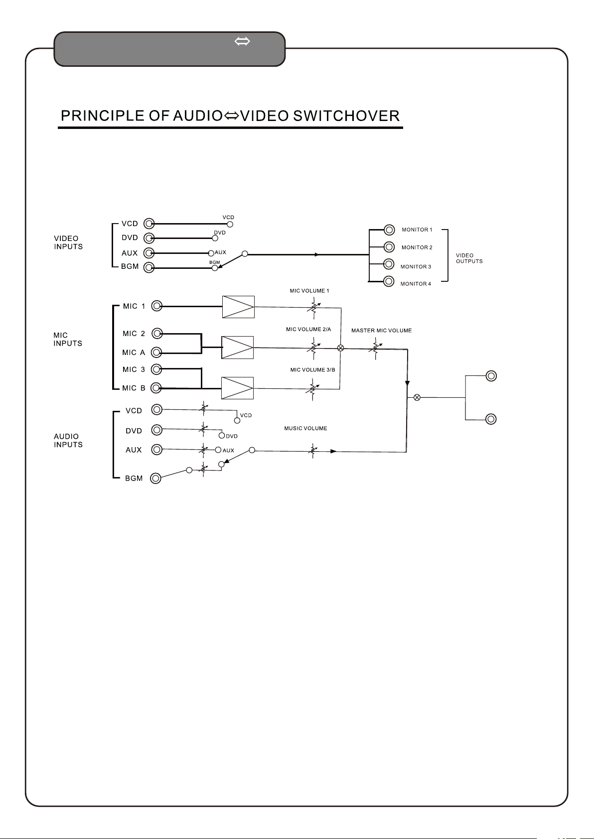
PRINCIPLE OF AUDIO
VIDEO SWITCHOVER
PR E-O UT
1
2
9
Page 12
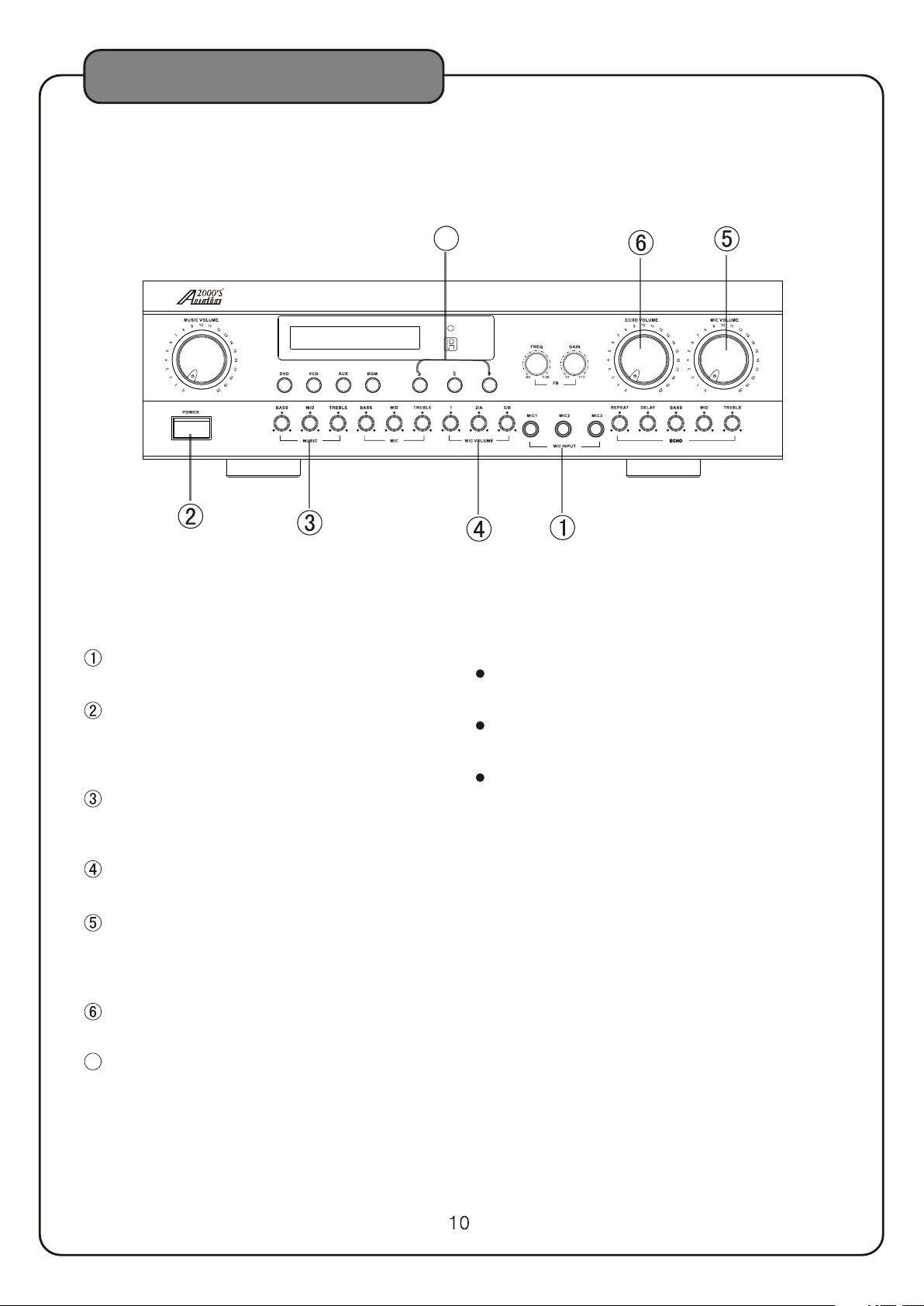
GENERAL OPERATION
AKJ 7404 PRO FESSI ONAL KA RAOKE M IXER WI TH DIGI TAL ECHO, KEY,AND F EEDBA CK CONT ROLS
7
AUTO
Connect a desired number of microphones to
the microphone inputs on the AKJ7404.
Turn on the power of the AKJ7404 and other
needed components.
(Press the POWER button on this unit to turn
on the power.)
Start playing the karaoke music from a source
component and turn the MUSIC VOLUME
control knob to adjust the music volume.
Adjust each microphone volume by adjusting
the INDIVIDUAL MIC VOLUME con tro l kno bs.
Adjust the desired relative volumes between
microphones and music by adjusting the
MASTER MIC VOLUME control knob and the
MUSIC VOLUME control knob.
Adjust the echo volume by adjusting the
ECHO VOLUME control knob.
7
Press the KEY CONTROL buttons to set the
desired key.
Notes for Proper Use of a Microphone
Hold a microphone to have the top of its windscreen
1 to 2 inches away from your mouth.
To get the best pickup result, point the microphone
toward your mouth.
To ensure a clear vocal output, do not block the lower
part of the microphone windscreen. Blocking the lower
part of the microphone windscreen will disturb the
proper voice reproduction with an unclear bass which
tends to cause the feedback (howling) results.
Page 13
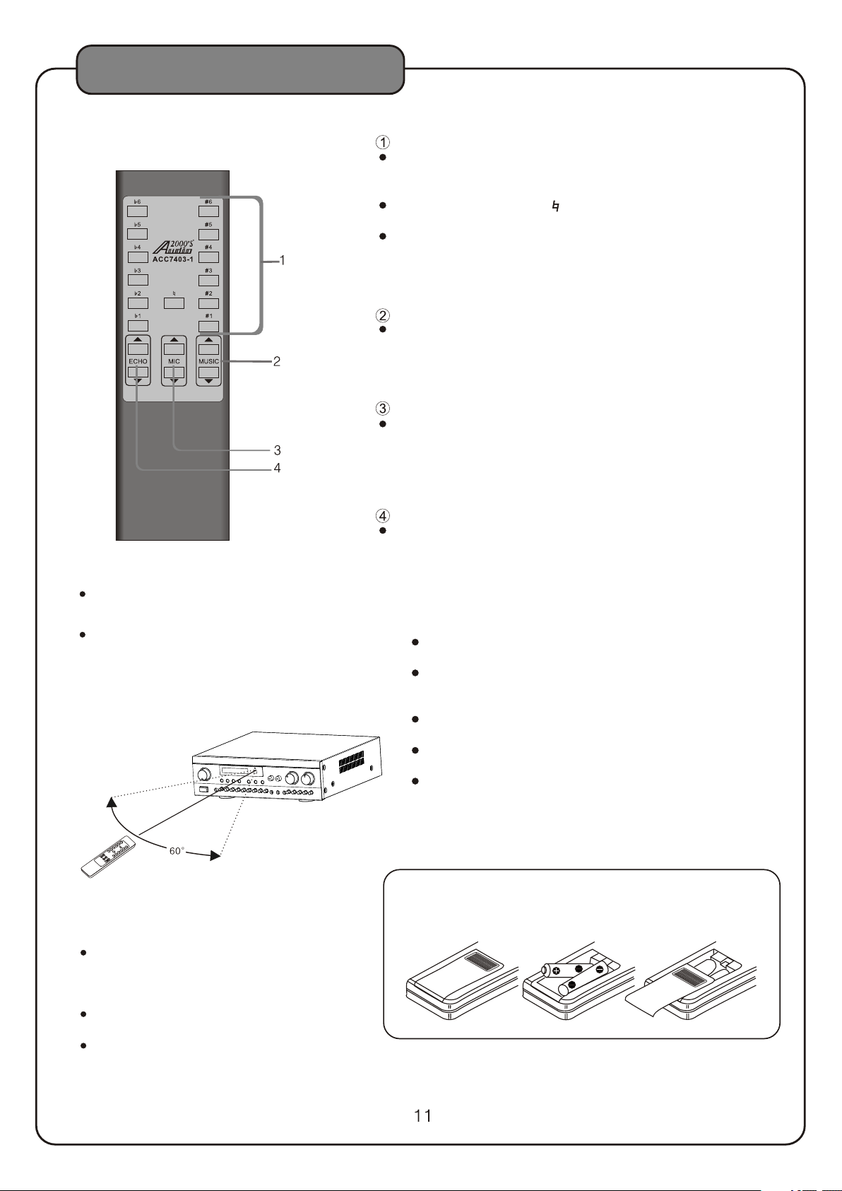
REMOTE CONTROL COMMANDER
DESCRIPTIONS AND FUNCTIONS
KEY CONTROL BU TTO NS
UPWARD BUTTONS(#1 to#6)
The key can be tra nsp osed upward from the n atural key up to
one and a half not es. ( Total 6 steps. Each s tep i s 1/4 note.)
NAT URA L KEY B UTTON ( )
Press to rese t to the natural key.
DOWNWARD BUTTONS (b1 TO b 6)
The key can be tra nsp osed downward from t he natural key up to
one and a half not es. ( Each step is 1/4 n ote )
Total 6 steps. .
MUSIC VOLUME
These music vo lum e control buttons ar e used to raise or reduc e
the music volu me. T he LED on the MUSIC VOLUME CONTROL
knob on the fron t pan el of the main unit blin ks during the
adjustment . A fin e adjustment is avai lable by pressing th e button
intermitte ntl y.
MIC VOLUME
These master m icr ophone volume cont rol buttons are used t o
raise or reduc e the m icrophone volume . The LED on the MASTER
MIC VO LUME CO NTROL knob on the fron t pan el of the main
unit blinks du rin g the adjustment. A fi ne adjustment is ava ilable
by pressing th e but ton intermittent ly.
ECHO VOLUME
Press one of th ese echo volume cont rol buttons to raise or
reduce the ech o vol ume.
.
1 Operating range
The op er ating ran ge o f the remot e co ntrol com m ande r is w ithin a dis ta nce of abou t 16 ft from the
remo te c ontrol se ns or on the amp li fier.
Do not p oi nt the tran sm itter on th e fr ont edge of t he
remo te c ontrol co mm ander to an y other direc tion
than t he r emote con tr ol sensor o f th e amplifi er or
leav e an o bstacle b et ween the re mo te contro l
and he amplifie r.
comm an der t
Doin g th ese may mak e re mote cont ro l impossi be
6ft
1
ut
Abo
Remote control
comma nder
2.Loading batte rie s
The battery li fe is a bout 1 year under
normal use, bu t it is r ecommended to
replace the ba tte ries when their powe r
seem to be weake n.
This remote co ntr ol commander accep ts
"AAA" batteries .
Remo ve the batteries if th e remote control
commander is n ot to b e used for a long
period of time.
3.Batter y han dling precaut ion s
Battery may ex plo de or its fluid may leak i f the batteries
are handled in a w ron g way. Take care of the foll owing
when handlin g the b atteries.
Insert batterie s with correct posit ive (+) and
negative(- ) pol arities as indicat ed on the set.
Even batteries wi th the same shape some times have
different vo lta ges. Do not mix batter ies with different
types togeth er.
Do not use new and old ba tteries together. When
replacing batte ries, be sure to repla ce both of them.
Do not heat, open or sh ort-circuit a b att ery or dispose
of it in fire.
Some batteries ar e rechargeable and s ome are not.
Check the indicat ion on each battery we ll.
1.Pus h th e ta b
and remove the
battery cover.
2.Insert batteries with
correct positive(+)and
negative(-)polarities.
"AAA" batteries X 2
3.Pus h th e co ve r
close until it clicks.
Page 14
SAFETY PRECAUTIONS
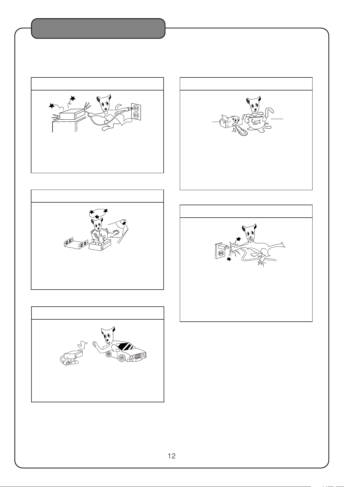
In case of abnorma lity
In case an ab normal noise or s mell is generat ed from
the unit du ring use, immed iately switch the power off,
unplug th e power cord from t he power outlet ,and
consult y our dealer or an au thorized service center
for a check-up.
Do not open the unit
Keep away from wat er and foreign objects
Do not inse rt or drop metall ic objects,su ch as a
hairpin ,nail and coin, or flammable ob jects,su ch as
paper and m atches,thro ugh the ventilation holes o r
other ope nings on the unit ,for this will ca use
malfunc tion or hazard of f ire and electri c shock. In
case wate r or a foreign obje ct enters insid e the unit,
consult a n authorized se rvice cent er or your dealer
for a check-up.
Do not damage the po wer cord
High-vo ltage compone nts are used inside the unit.
Do not open t he cabinet to che ck or modify the un it,
for this wi ll cause the dang er of electric shock.
Performance d egradati on or malfuncti on due to the
user modi fication will n ot be covered by th e warranty.
When the uni t is no t to be u sed f or a lo ng pe riod
When you wi ll be away from hom e for a long period
of time,f or example befo re going on a trip, set the
power swi tch to off and unpl ug the power plug f rom
the power o utlet for safet y. This will prev ent fire
hazard du e to unexpected a ccidents with the unit
Hold the po wer plug when plu gging or unplug ging
the power c ord. Do not pull th e cord or touch it wi th
wet hands ,for this may cau se short-c ircuit or elect ric
hazard. D o not leave the pow er cord under thi s unit,
or under fu rniture,or be tween objects.Also do not t ie
the power c ord with anothe r cord,make a kno t on the
power cor d,or leave it in a pl ace where peopl e walk
frequen tly.
Page 15
TROUBLESHOOTING
MAINTENANCE
When the set gets dirty, wipe with a soft, dry cloth. If
the set is extremely dirty, soak a soft cloth in a 5 to 6%
solution of dishwashing detergent to water, wring it
tightly, wipe the dirt away, and finally wipe the set with
a dry cloth.
Never use alcohol, thinner, benzine, insecticide or other
volatile agents, as they may damage the surface paint
or gloss of the set.
Also do not wipe the set with a chemical cloth or leave
it on the set for a long period, as the surface finish may
be damaged or the paint may be stripped off.
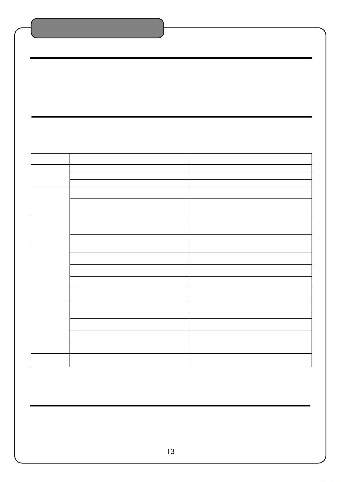
TROUBLESHOOTING
Should problems occur, they are, in many cases, due to If the problem cannot be remedied after the following
simple operation mistakes or the like. On the basis of checks, please cons ult y our d eal er.
the following checks, you will be able to rectify a
number of problems yourself without difficulty.
PROBLEM
No power
One Sid e
No Sound
Disto rted
sound
No soun d
No microphone so und
Hummi ng
noise
POSSI BLE CAUSES
Power i s off.
AC power c or d is unplug ged. Plug t he A C po wer cord to a n AC p ow er outlet ( 120V).
The fu se i nside the t ransfor me r is open. Send t he mixer to an au thorize d service cen ter.
One ba d RC A cable or on e poor RCA co ntact.
One U-sh aped conn ec tor is not in serted in to t he
musi c ef fect jack s or one U-shap ed connec to r is not
prop erly insert ed.
The el ec trical si gnal from t he o utput of th e player to
the mi xe r is over the l imit of the i nput of the mix er.
Inco rrect AC Voltage ( The AC power cord i s plugged
to a 240 V outlet or t o an u nstable 1 20V outle t) .
Inco rrect input s electio n. Make sure the input source selection but ton is set correctly.
The in pu t level on th e rear pane l is set to the min imum
posi ti on.
Musi c vo lume cont rol knob is t urned all the w ay down
(zer o so und outpu t).
Both U-s haped con ne ctors are n ot insert ed i nto the
musi c ef fect jack s or not prop er ly insert ed.
Bad ca ble or poor con tact.
The mi cr ophone ca ble is not pl ugged into th e
micr op hone inpu t jack prop erly.
The sw it ch on the mic rophone i s set to “OF F”. Set th e sw itch on the m icropho ne to “ON” .
The corresponding INDIVIDUAL MIC VOLUME control or the
MASTER MIC VOLUME control is in the minimum position.
The U-sh aped conn ec tor is not in serted in to t he MIC
EFFE CT jacks or not p roperly i nserted.
A cond enser micro phone is us ed.
Grounding problems between two adjacent equipments.
Turn o n the mixer.
Make s ur e that all RC A cables ar e no t damaged a nd all
RCA co ntact point s are prope r.
Make s ur e all the U-s ha ped conne ctors are p ro perly
inse rt ed.
Turn d own the mas te r volume co ntrol of th e pl ayer and
turn u p th e volume co ntrol of th e mixer to main tain the
same s ou nd level.
Make s ur e the AC power co rd is plugg ed t o an AC power
outl et w ith a corre ct and stab le AC vo ltage.
Adju st t he input le vel contr ol .
Turn t he music vo lu me knob to a po sition th at t he
soun d le vel is desi red.
Make s ur e all the U-s ha ped conne ctors are p ro perly
inse rt ed.
Make s ur e that all ca bles are no t damaged and a ll
cont ac t points ar e proper.
Make s ur e the micro phone cab le is plugged i nto the
micr ophone jack p roperly.
Adju st t he volume c ontrol.
Make s ur e the U- sha pe d connect or is prope rl y inserte d
into t he MIC EFFECT j acks.
Change the co ndenser microphone to a dynamic microphone or a condenser microphone acc ep ting battery power.
Try to u se an isola to r to remove t he ground in g problem s.
SOLUTIONS
ETIQUETTE OF SOUND
The karaoke performance you enjoy may be disturbing noise to others.When performing karao ke, be su re to b e
considerate of your neighbors.
The volume of karaoke is at your command. Remember that even small sounds transmit very well in the quiet night.
Be specially careful in karaoke performance at night.it is recommended to close the windows t o avo id so und
leakages to the neighbors.Avoid noise pollution to protect the comfortable living en vir onm ent o f tho se ar oun d you .
Page 16
SPECIFICATIONS
Mixer
Total Harmonic Distortion ............................ 0.03%
Input Jacks(Sensitivity/Impedance)
Ω
MIC(1 ,A/2,B/3) ....................... ... ... 3 .5m V/5 k
Ω
DVD,V CD,AUX, TAPE ...................... 220mV/23k
Ω
BGM .............................. ... ... ... ... 2 20mV/30k
Output Jacks(Output level/Output impedance)
PRE OUT ......................... ... ... ... ... ... .. 2V/150
Ω
Frequency Responses
MIC ........................... .. 20 Hz to 2 5kH z,+ 3/- 3dB
MUSIC ......................... 1 0Hz t o 20k Hz, +3/ -3d B
Tone Control Characteristics
Music BASS ............. ... . +7/ -7d B(1 00H z)
MID ......... ... ... ... .. +5 /-5 dB( 2KHz)
TREBLE ...... ... ... . +7/ ~7d B(1 0KH z)
Microphone BASS ..............+10 /-1 0dB (10 0Hz )
MID ......... ... ... ... .. +5 /-5 dB( 2KHz)
TREBLE ...... ... .. +1 0/- 10d B(1 0kH z)
Key Co ntr ol Range ...................... 13 steps, 3tones
±
Video Input Jack
Ω
(Sensitivity/Input impedance) ............ 1Vp-p/75
Video Output Jack
Ω
(Output level/Output impedance) ...... 1Vp-p/75
Pow er Su ppl y
Supply Voltage .............. AC 115V/230V 50Hz/60
Power Consumption ............. ... ... . .................30W
..
Hz
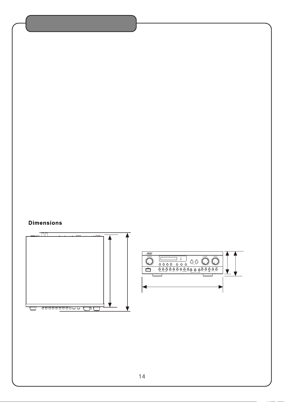
Dimensions(W X H X D)-------------17.0'' X 5.2'' X 17. 1''
Weight.................. ... ... ... ... ... ................... 14.3lbs
Accessories
Remo te Co ntr ol Unit ........................................... 1
AAA Batteries ...................... ... ... ... ... ... ...............2
Rack M oun ts. ......................................................2
Owner' s Manual ......................... ... ... ... ... ... ........ 1
Warranty Card................ ... ... ... ... ... ..................... 1
RCA Cord.......................... ... ... ... ... ... ... ..............1
AKJ740 4 PROFESSI ONAL KAR AOKE M IXER WIT H DIGI TAL ECHO,K EY,AND F EEDBAC K CONT ROLS
15 .4 ''
17 .1 ''
AUTO
17 .0 ''
4. 7''
5. 2''
Page 17

SERVICE INFORMATION
SERVICE INFORMATION
SHIPPING DAMAGE
If the sh ipping carton is found to be damaged, not ify the delivery company immediately.
Save th e damaged carton as evidence for the delivery company to inspect. It is the
respo nsibility of the consignee to file a claim with the delivery company for any damaged
that occurs during shipping. In the case that the shipping carton is in good condition but
the uni t is damaged or defective, call A udi o20 00' S at 805-523-2759.
®
FACTORY SERVICE
If the equipment needs factory service, call A udio 200 0'S at 805-523-2759 for a Return
Autho rization number (RA number) and the address of the authorized service
repre sentatives. Insure and ship the product, prepaid, i n its original carton along with
proof of purchase in the form of a bill of sale or recei pted invoice to the above address.
Pleas e clearly write the RA number on the shipping carton. Also enclose a note
descr ibing the problem along with any other helpful information such as where and
how the unit was used.
®
LIMITED WARRANTY
H&F Technologies, Inc orporated (H&F) hereby warrants that A udi o20 00' S products will be
free fr om defects in material and workmanship for a period of 1 (one) year from date of
purch ase. At its option, H&F will repair or repl ace the defective product and promptly
retur n it to you.
The Limited Warranty will not cov er any item that has been, in H&F's estimation,
subje ct to alteration, misuse, neglect, accident or improper installation. In addition,
any ser vice not performed by H&F or an authorized service center will terminate terms
of this w arranty. Normal wear and tear of this product will not be covered by this o r any
impli ed warranty.
No liability will be accepted for damages/loss directly caused from the use of
this pr oduct.
H&F's l iability shall be limited to the repair/replacement of this product if found
to be defective.
®
© 2009 H & F Technologies, Incorporated (website: www.audio2000s.com)
 Loading...