

Audi A6 242, A6 Service Manual
Service.
For internal use only
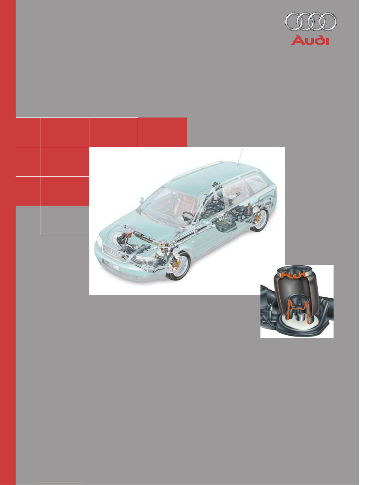
Pneumatic suspension system
Par t 1
Selflevelling suspension
in the Audi A6
Design and Function
Self-study programme 242
242
2
242_067
Pneumatic self-levelling suspension system
The 4-level air suspension of the Audi
allroad quattro is described in selfstudy program 243.
You will find further information on the
Audi allroad quattro in self-study
programme 241.
Principles of spring suspension, damping and
air suspension
Self-levelling suspension, A6
The rear axle air suspension system for the
Audi A6 Avant is described here.
242_046
242_048
This self-study programme is divided into two
parts:

3
Contents
Principles
Vehicle suspension.................................................................. 4
The suspension system .......................................................... 6
Vibration................................................................................... 8
Characteristic values of springs .......................................... 12
Conventional running gear without self-levelling ............ 14
The self-study programme is not intended as a workshop manual.
The self-study programme will provide you with
information on design and functions.
New
Note
Important:
Note
Page
For maintenance and repairs please refer to the current
technical literature.
Principles of air suspension
Self-levelling air suspension ............................................... 16
Characteristic values of air spring ...................................... 21
Vibration damping................................................................. 23
Shock absorbers (vibration dampers) ................................ 25
PDC shock absorbers ........................................................... 33
System overview ................................................................... 38
Air springs.............................................................................. 40
Air supply unit........................................................................ 42
Diagram of pneumatic system............................................. 43
Compressor ........................................................................... 44
Air dryer ................................................................................. 47
Discharge valve N111 ........................................................... 48
Valve for suspension struts N150 and N151....................... 51
Self-levelling suspension sender G84 ................................ 52
Self-levelling suspension control unit J197 ....................... 54
Self-levelling suspension warning lamps K134 ................ 55
Function diagram ...................................................................56
Interfaces................................................................................ 57
The control concept .............................................................. 58
Other features of the control concept ................................ 60
Self-levelling suspension, A6
4
Vehicle suspension
When a vehicle travels over irregular road
surfaces, impact forces are transmitted to the
wheels. These forces pass to the bodywork
via the suspension system and the wheel
suspension.
The purpose of the vehicle suspension is to
absorb and reduce these forces.
Principles
Wheel contact with the road surface, which
is essential for braking and steering, is
maintained.
The vehicle components are protected
against excessive stresses.
Unpleasant and unhealthy stresses to vehicle
passengers are minimised, and damage to
fragile loads is avoided.
242_003
Driving safety
Operating safety
Driving comfort
When we talk about the vehicle suspension
we can basically distinguish between the
suspension system and the vibration
damping system .
By means of the interaction of the two
systems, the following is achieved:
5
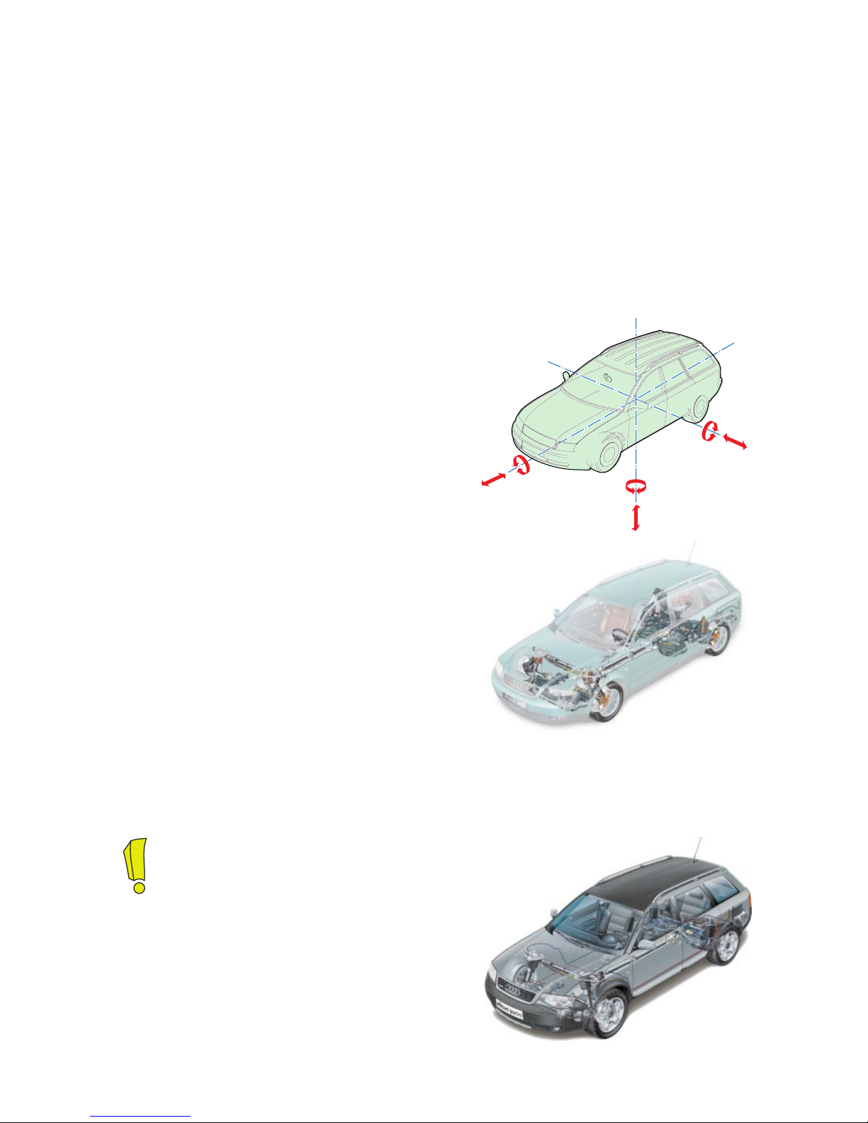
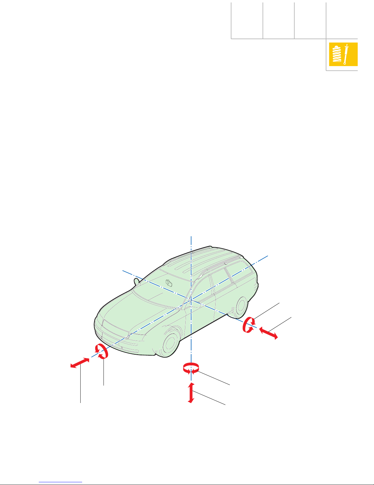
During driving operation, the vehicle body is
subject not only to the forces which cause the
upward and downward motion of the vehicle,
but also the movements and vibrations in the
direction of the three spatial axes.
Along with the axle kinematics, the vehicle
suspension has a significant influence on
these movements and vibrations.
242_048
Longitudinal axis
Transverse axis
Vertical axis
Drift
Pitch
Swerving (yaw)
Rising and sinking
Tipping (roll)
Jerking
The correct matching of the springs and
vibration damping system is therefore of
great significance.
6
Principles
The suspension system
As ”supporting” components of the
suspension system, the suspension elements
form the connection between the wheel
suspension and the bodywork. This system is
complemented by the spring action of the
tyres and vehicle seats.
The suspension elements include steel
springs, gas/air and rubber/elastomers or
combinations of the above.
Steel spring suspensions have become well
established in passenger vehicles. Steel
springs are available in a wide variety of
designs, of which the coil spring has become
the most widespread.
Air suspension, which has been used for
many years in heavy goods vehicles, is
finding increasing application in passenger
vehicles due to its system-related
advantages.
242_047
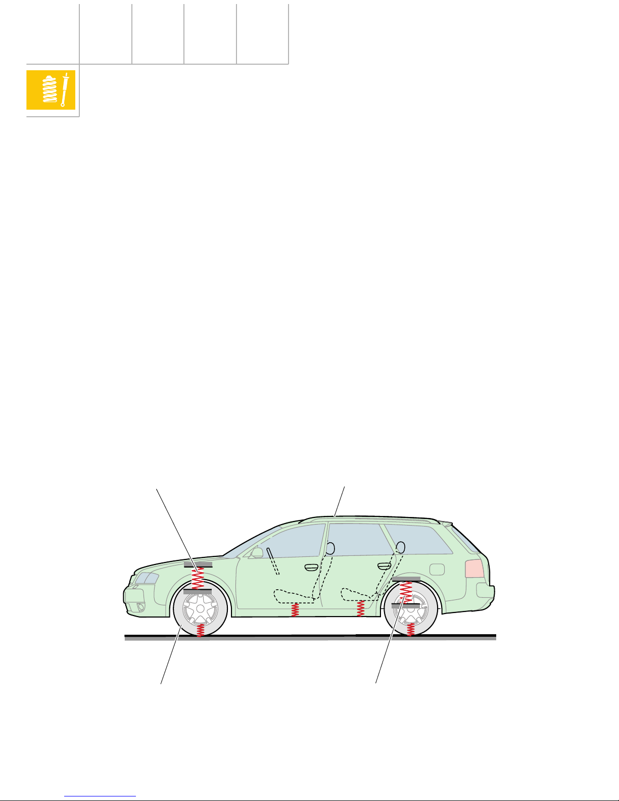
In the case of the passenger vehicle we can
differentiate between sprung masses (body
with drive train and parts of the running gear)
and unsprung masses (the wheels, brakes
and parts of the running gear and the axle
shafts).
As a result of the suspension system, the
vehicle forms an oscillatory unit with a
natural frequency of the bodywork
determined by the sprung masses and the
matching of the suspension system (see
”Vibration” chapter).
Sprung mass
Unsprung mass
Suspension element
Suspension element
7
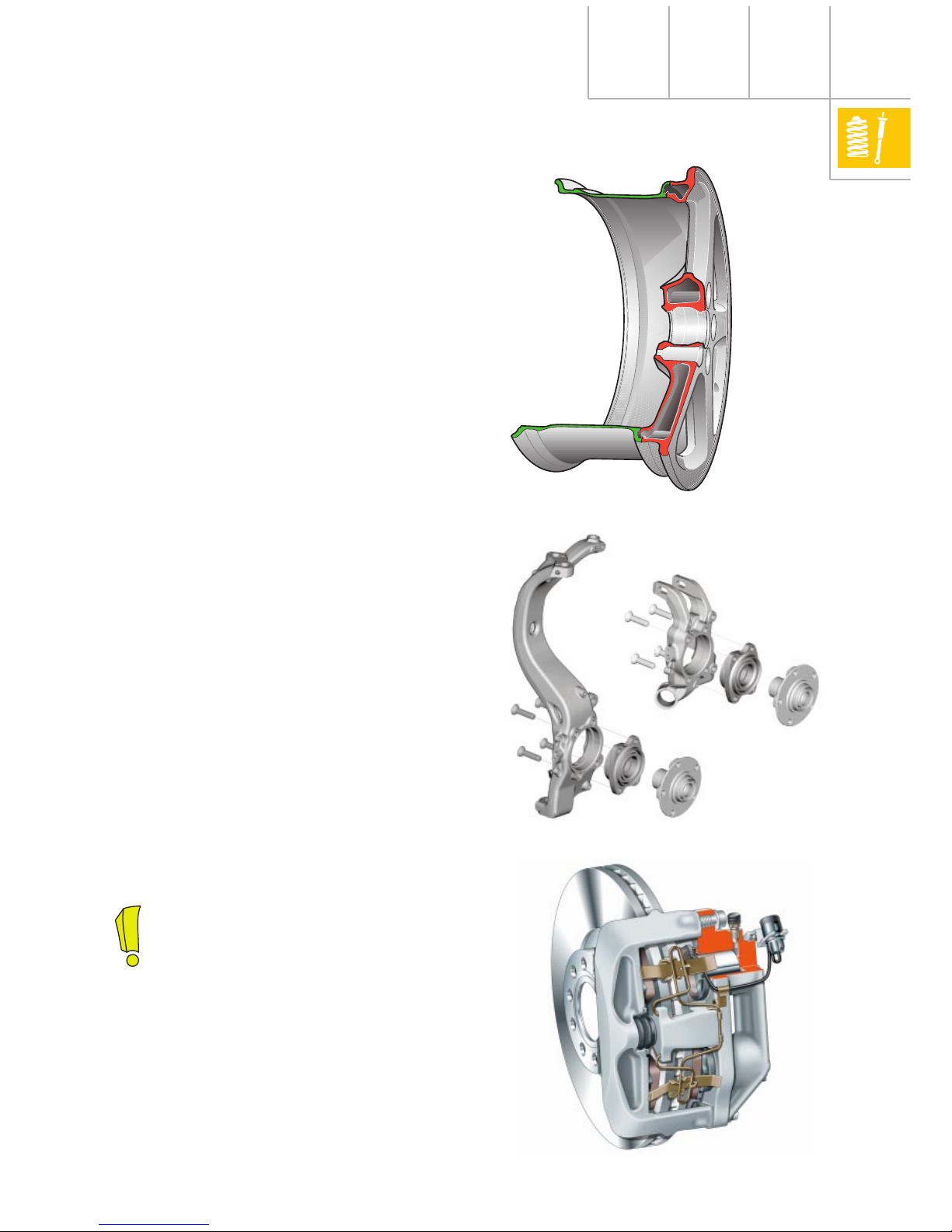
The unsprung masses
The aim in principle is to minimise the volume
of unsprung masses and their influence on
the vibration characteristics (natural
frequency of the bodywork). Furthermore, a
low inertia of masses reduces the impact load
on the unsprung components and
significantly improves the response
characteristics of the suspension. These
effects result in a marked increase in driver
comfort.
Examples for the reduction of unsprung
masses:
• Aluminium hollow spoke wheel
• Running gear parts (swivel bearing, wheel
carrier, links etc.) made of aluminium
• Aluminium brake callipers
• Weight-optimised tyres
• Weight optimisation of running gear parts
(e.g. wheel hubs)
213_091
213_068
See also SSP 213, chapter “Running
gear”.
213_041
8
Principles
The natural frequency of the bodywork
The vibrations are defined by the degree of
amplitude and its frequency. The natural
frequency of the bodywork is particularly
important during matching of the
suspension.
The natural frequency of unsprung parts is
between 10 Hz and 16 Hz for a medium-size
vehicle. Appropriate matching of the
suspension system reduces the natural
frequency of the bodywork (sprung mass) to
between 1 Hz and 1.5 Hz.
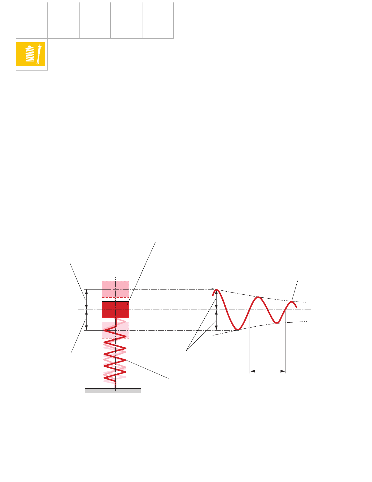
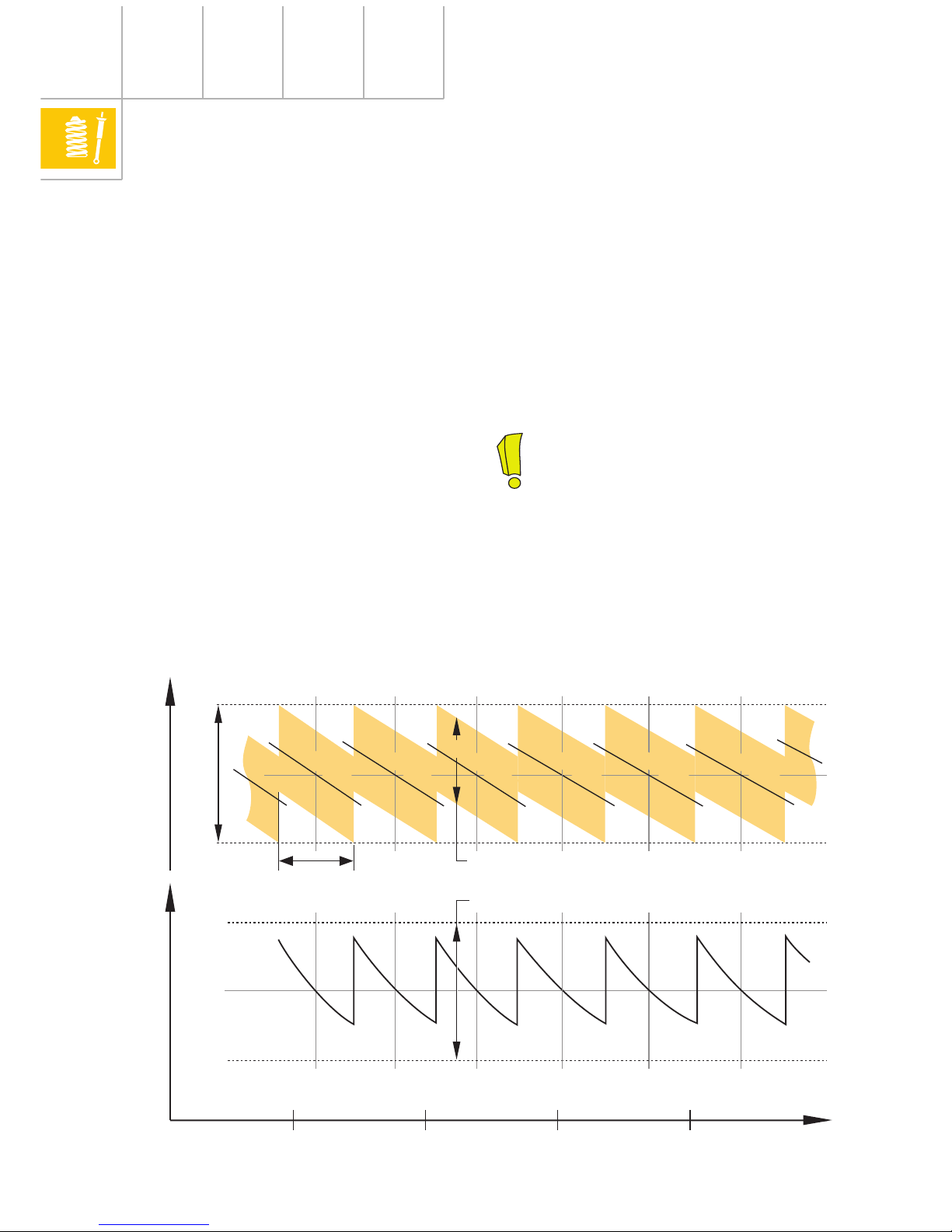
Vibration
If a mass on a spring is deflected from its rest
position by a force, a restoring force develops
in the spring which allows the mass to
rebound. The mass oscillates beyond its rest
position which results in a further restoring
force being exerted. This process is repeated
until air resistance and the internal friction of
the spring causes the vibration to cease.
242_021
Rest position
Mass
Spring
Vibration
Rebound
Compression
1 cycle
Amplitude
9
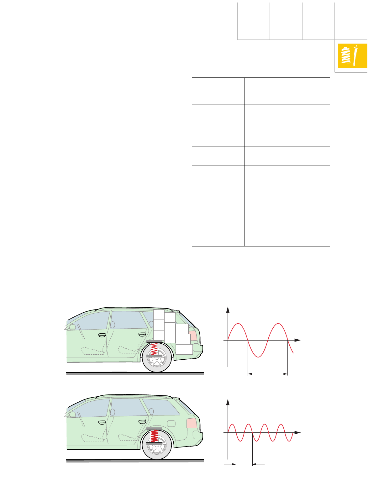
The natural frequency of the bodywork is
essentially determined by the characteristics
of the springs (spring rate) and by the sprung
mass.
Greater mass or softer springs produce a
lower natural frequency of the bodywork and
a greater spring travel (amplitude).
Smaller mass or harder springs produce a
higher natural frequency of the bodywork and
a lesser spring travel.
Depending on personal sensitivity, a natural
frequency of the bodywork below 1 Hz can
cause nausea. Frequencies above 1.5 Hz
impair driving comfort and are experienced
as shudders above around 5Hz.
242_072
Definitions
Vibration Upward and downward
motion of the mass
(body)
Amplitude The greatest distance of
the vibrating mass from
the rest position
(vibration extent, spring
travel)
Cycle Duration of a single
vibration
Frequency Number of vibrations
(cycles) per second
Natural
frequency of
the bodywork
Number of vibrations of
the sprung mass (body)
per second
Resonance The mass is disturbed in
its rhythm by a force
which increases the
amplitude (build-up).
Greater mass or softer springs
Smaller mass or harder springs
Spring travelSpring travel
Low natural frequency of the
bodywork
High natural frequency of the
bodywork
1 cycle
1 cycle
Time
Time
10
The degree of damping of the vibration
damper has no significant influence on the
value of the natural frequency of the
bodywork. It influences only how quickly the
vibrations cease (damping coefficient). For
further information, see chapter “Vibration
damping”.
Matching of the natural frequency of the
bodywork
The axle loads (sprung masses) of a vehicle
vary, at times considerably, depending on the
engine and equipment installed.
To ensure that the bodywork height
(appearance) and the natural frequency of the
bodywork (which determines the driving
dynamics) remains practically identical for all
vehicle versions, different spring and shock
absorber combinations are fitted to the front
and rear axles in accordance with the axle
load.
For instance, the natural frequency of the
bodywork of the Audi A6 is matched to 1.13Hz
on the front axle and 1.33Hz on the rear axle
(design position).
The spring rate of the springs therefore
determines the value of the natural frequency
of the bodywork.
The springs are colour-coded to differentiate
between the different spring rates (see table).
Principles
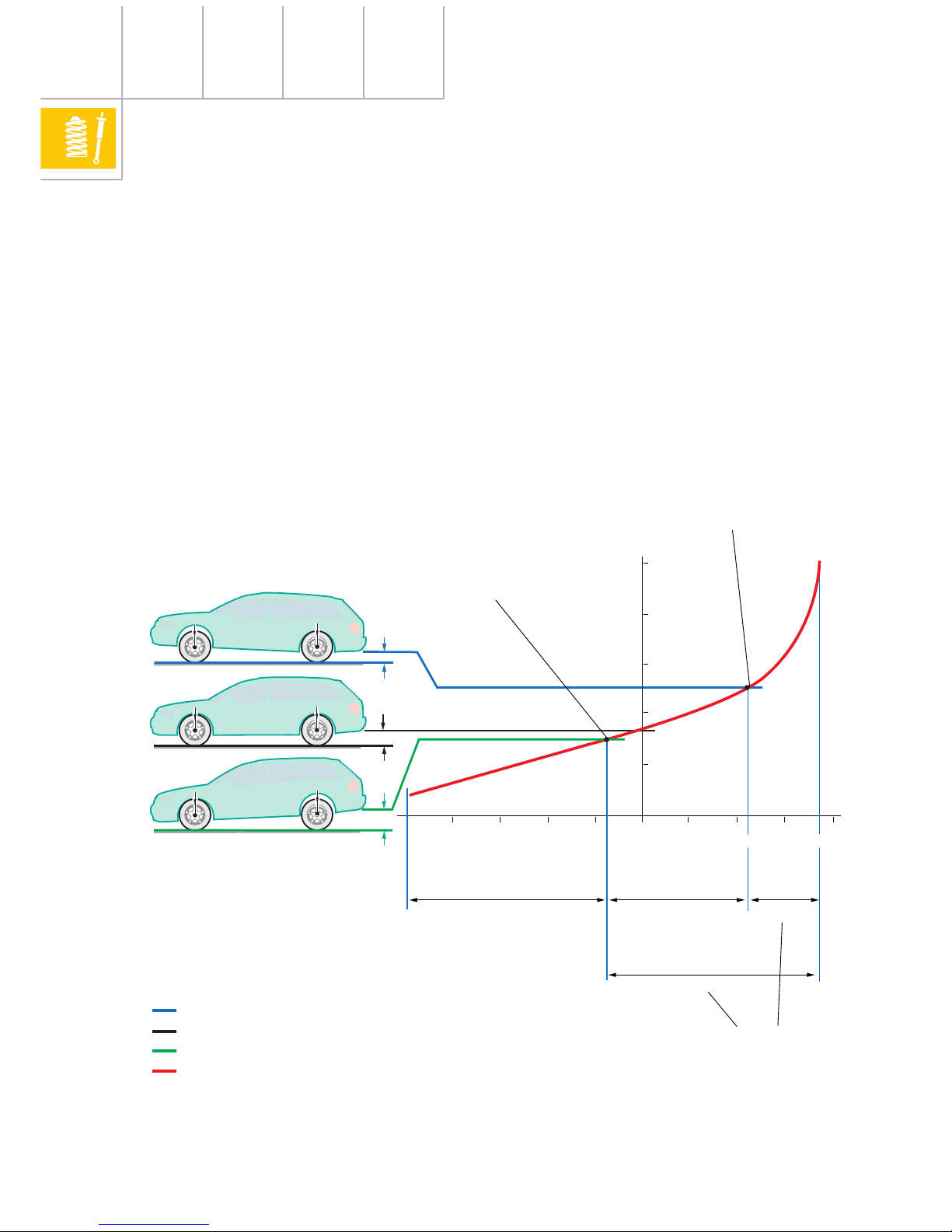
For standard running gear without selflevelling, the rear axle is always
matched to a higher natural frequency
of the bodywork because when the
vehicle is loaded, it is principally the
load to the rear axle which increases,
thus reducing the natural frequency of
the bodywork.
242_073
Vehicle heightNatural frequency of the bodywork
Component tolerance band
Natural frequency tolerance band
Usable load range
of a spring
Height tolerance
Axle load800 kg 850 kg 900 kg 950 kg
1.13 Hz
c
F1
= 33.3 N/mm
c
F2
= 35.2 N/mm
c
F3
= 37.2 N/mm
c
F4
= 39.3 N/mm
c
F5
= 41.5 N/mm
c
F6
= 43.7 N/mm
Spring rate levels of the front axle for the A6
11
OJL
1BA
OYF
Spring allocation table (e.g. A6 front axle 1BA)
PR-No. weight
class, front axle
Axle load (kg) Suspension, left and right
(spring rate)
Colour coding
Standard
running
gear
e.g. 1 BA
OJD 739 - 766 800 411 105 AN (29.6 N/mm) 1 violet, 3 brown
OJE 767 - 794 800 411 105 AP (31.4 N/mm) 1 white, 1 brown
OJF 795 - 823 800 411 105 AQ (33.3 N/mm) 1 white, 2 brown
OJG 824 - 853 800 411 105 AR (35.2 N/mm) 1 white, 3 brown
OJH 854 - 885 800 411 105 AS (37.2 N/mm) 1 yellow, 1 brown
OJJ 886 - 918 800 411 105 AT (39.3 N/mm) 1 yellow, 2 brown
OJK 919 - 952 800 411 105 BA (41.5 N/mm) 1 yellow, 3 brown
OJL 953 - 986 800 411 105 BM (43.7 N/mm) 1 green, 1 brown
OJM 987 - 1023 800 411 105 BN (46.1 N/mm) 1 green, 2 brown
Sports
running
gear
e.g. 1BE
OJD 753 - 787 800 411 105 P (40.1 N/mm) 1 grey, 3 violet
OJE 788 - 823 800 411 105 Q (43.2 N/mm) 1 green, 1 violet
OJF 824 - 860 800 411 105 R (46.3 N/mm) 1 green, 2 violet
OJG 861 - 899 800 411 105 S (49.5 N/mm) 1 green, 3 violet
OJH 900 - 940 800 411 105 T (53.0 N/mm) 1 yellow, 1 violet
OJJ 941 - 982 800 411 105 AA (56.6 N/mm) 1 yellow, 2 violet
OJK 983 - 1027 800 411 105 AB (60.4 N/mm) 1 yellow, 3 violet
Weight class of
front axle
Running
gear
Weight class of
the rear axle
242_108
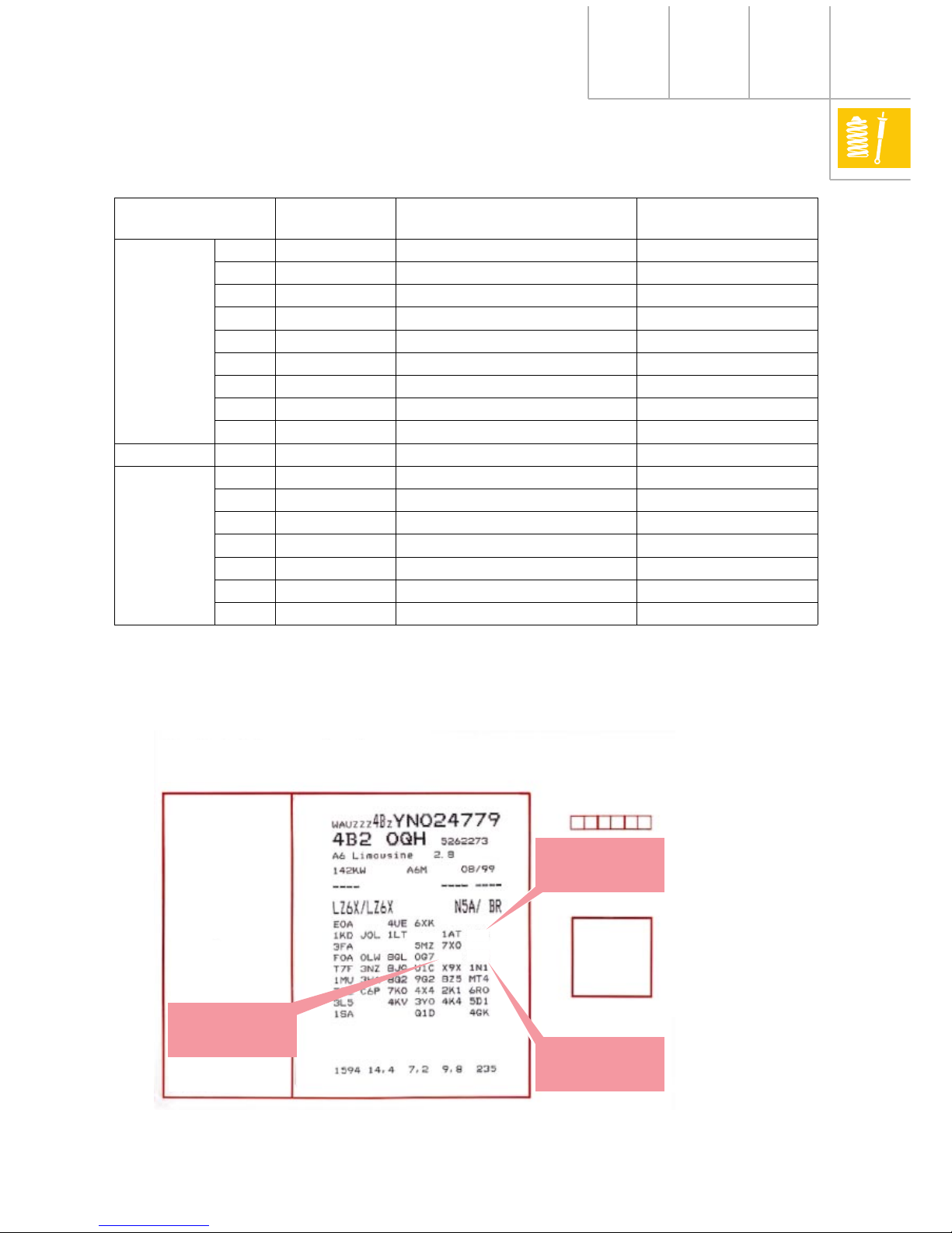
Proof of warranty
Vehicle data
Vehicle identification number
Type description
Engine capacity / gearbox / month/
year of manufacture
Engine code / gearbox
code letters
Paint no. / interior equipment no.
M-equipment number
Un-laden weight / consumption
figures / CO
2
emissions
Date of
Delivery
Stamp of the
Audi delivery
centre
12
0
0
Characteristic values of
springs
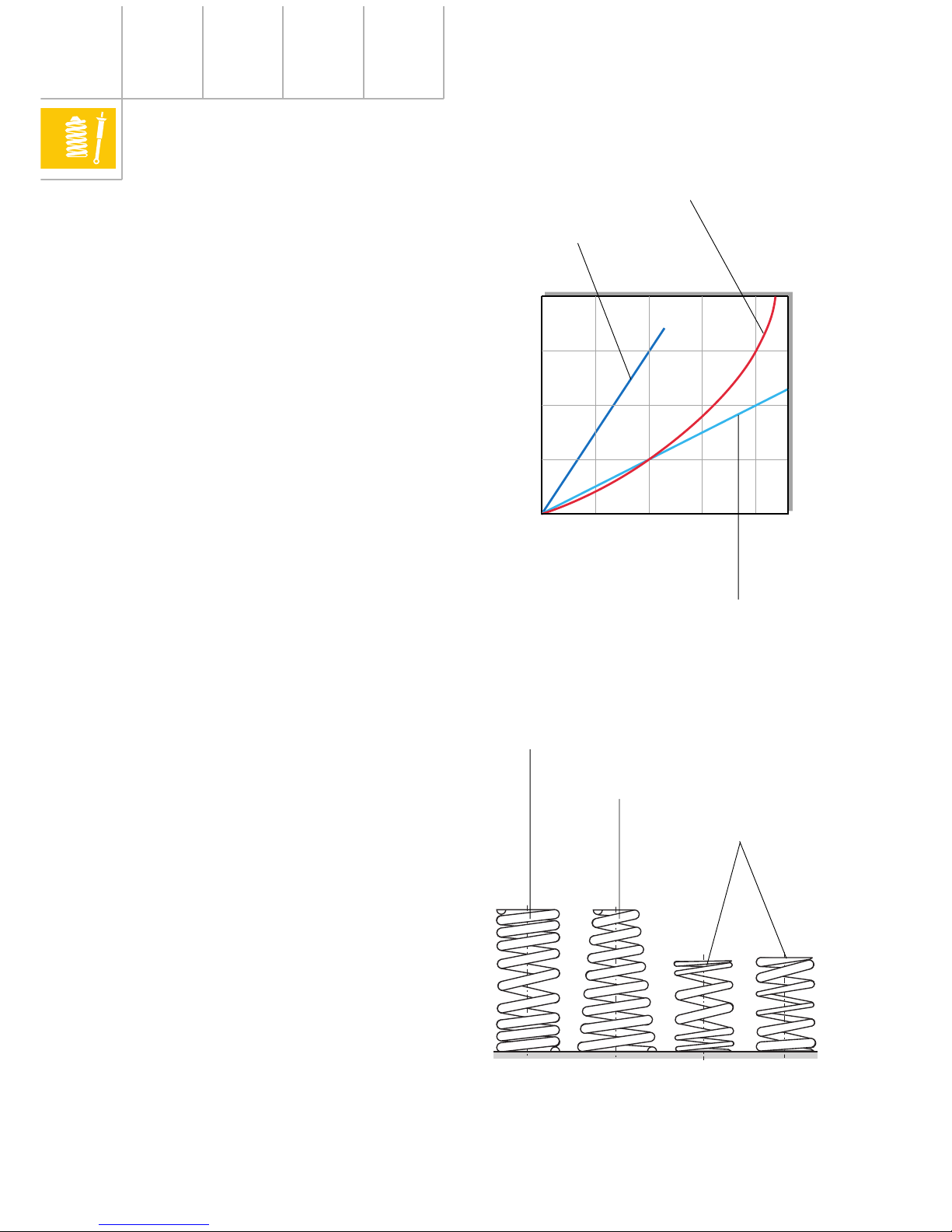
Characteristic curve/spring rate of springs
We can obtain the characteristic curve of a
spring by producing a forces/travel diagram.
The spring rate is the ratio between the
effective force and the spring travel. The unit
of measurement for the spring rate is N/mm.
It informs us whether a spring is hard or soft.
If the spring rate remains the same
throughout the entire spring travel, the spring
has a linear characteristic curve.
A soft spring has a flat characteristic curve
while a hard spring has a steep curve.
A coil spring is harder due to:
• a greater wire diameter
• a smaller spring diameter
• a lower number of coils
Principles
242_018
If the spring rate becomes greater as the
spring travel increases, the spring has a
progressive characteristic curve.
Coil springs with a progressive characteristic
curve can be recognised as follows:
a) uneven coil pitch
b) conical coil shape
c) conical wire diameter
d) combination of two spring elements
(example, see next page)
242_019
Spring travel s
Resilience F
Linear characteristic curve
Hard spring
Progressive characteristic
curve
a
b
c
Linear characteristic curve
Soft spring
13
-120 -80-400
0
3
6
9
12
15
40 80 120
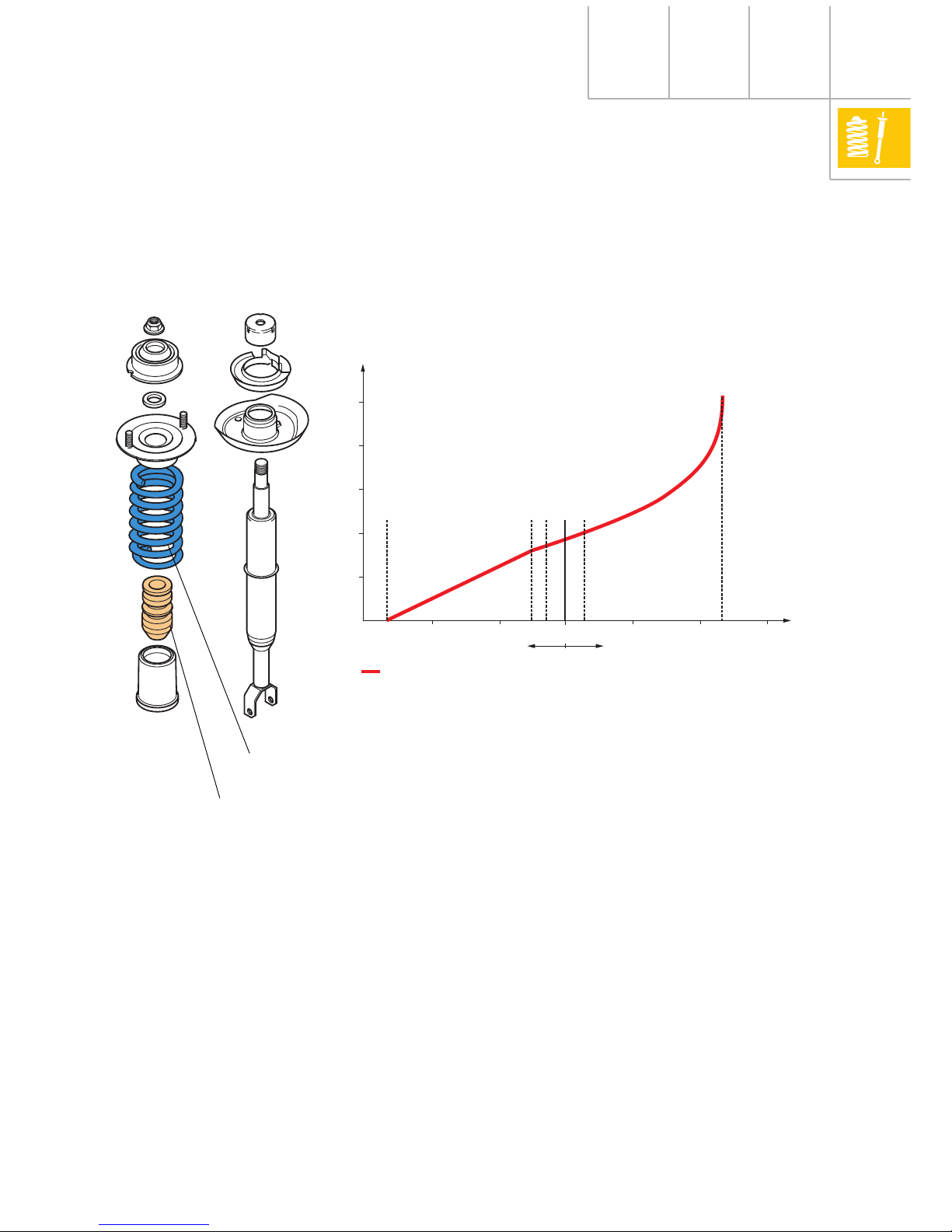
(Example: Suspension strut with auxiliary
polyurethane springs).
Advantages of progressive characteristic
curve of spring:
• Better matching of the suspension system
from normal to full load.
• The natural frequency of the bodywork
remains practically constant during
loading.
• The suspension is not so prone to impacts
in the case of significant irregularities in
the road surface.
• Better use of the available spring travel.
Rebound in mm Compression in mm
Parallel springing
Lower stop
Upper stop
Rebound stop insert (in shock absorber)
Un-laden position
Design position
Auxiliary spring insert
Lower stop
242_020
Spring
Auxiliary spring
14
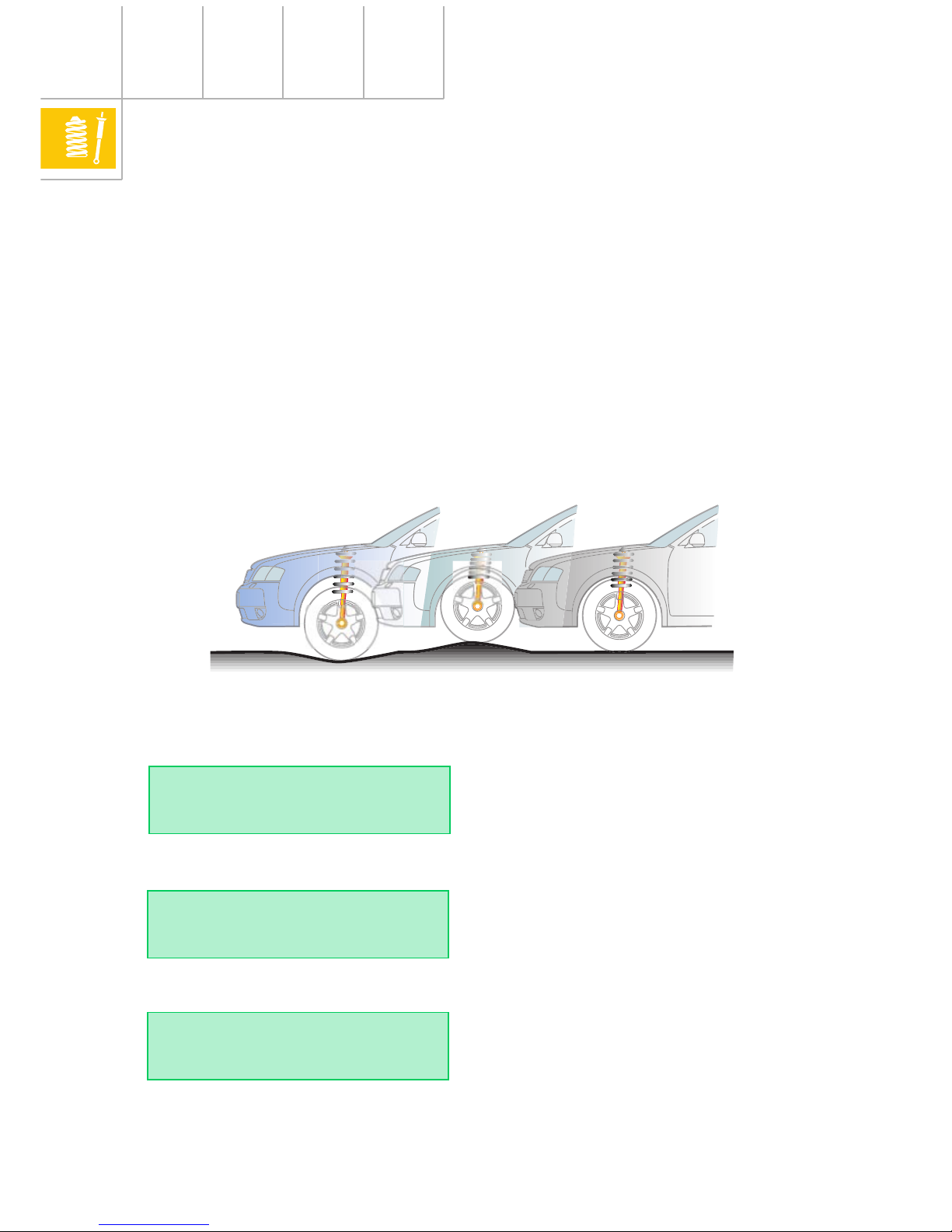
When the vehicle is stationary, the vehicle
body retracts by a certain spring travel
depending upon the load. In this case, we
speak of static compression: s
stat
.
The disadvantage of conventional running
gear without self-levelling is its reduced
spring travel at full load.
Conventional running gear
(steel springs) without selflevelling
Spring travel
The overall spring travel s
tot
required for
running gear without self-levelling is
comprised of the static compression s
stat
and
the dynamic spring travel caused by vehicle
vibrations s
dyn
for both laden and un-laden
vehicles.
s
tot
= s
stat
+ s
dyn(un-laden)
+ s
dyn(fully laden)
Principles
242_075
Steel suspension
fully laden
Design position
Un-laden position
Supporting force in kn.
H
V
H
H
L
dyn. rebound
s
stat
(un-laden)
dyn. compression
(un-laden)
(fully laden)
10
8
6
4
2
+80 mm
-40 mm-80 mm
H
V
= height when fully laden
H
= design position height
H
L
= height when un-laden
Characteristic curve of spring
s
stat(un-laden)
s
stat(fully laden)
+40 mm
0
15
Definitions:
The un-laden position ...
... is the compression exerted onto the wheels
when the vehicle is ready for the road (fuel
tank completely filled, spare wheel and
vehicle tools present).
The design position ...
... is defined as the un-laden position plus the
additional load of three persons, each
weighing 68 kg.
The static compression ...
... is the starting point (zero) for the dynamic
spring movements, compression travel (plus)
and rebound travel (minus).
... is dependant upon the spring rate and the
load (sprung masses).
... results from the difference between the
static compression when un-laden
s
stat(un-laden)
and the static compression when
fully laden s
stat(fully laden)
.
s
stat
= s
stat(fully laden)
- s
stat(un-laden)
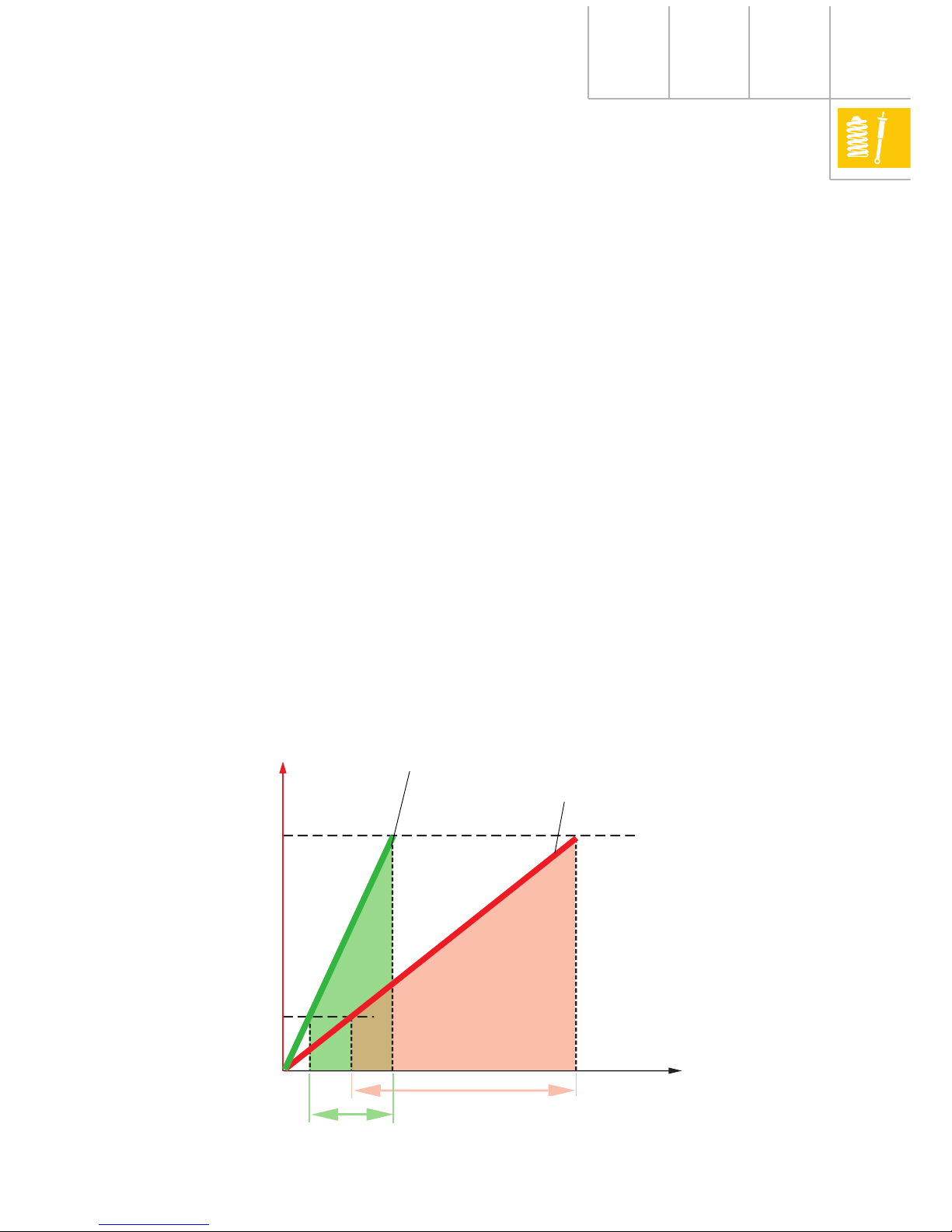
In the case of a flat characteristic curve (soft
springs), the difference and thereby the static
compression between full and un-laden is
very great.
242_076
In the case of a steep characteristic spring
curve, this state of affairs is reversed and is
coupled with an excessive increase of the
natural frequency of the bodywork.
Fully laden
Un-laden position
Hard springs
Soft springs
s
stat
soft springs
s
stat
hard springs
16
Principles of air suspension
Self-levelling air
suspension
Air suspension is a controllable form of
vehicle suspension.
With air suspension, it is simple to achieve
self-levelling and it is therefore generally
integrated into the system.
The basic advantages of self-levelling are:
• Static compression remains the same,
irrespective of vehicle loads (see overleaf).
The space requirement in the wheel
arches for free wheel movement kept to a
minimum, which has benefits for the
overall use of available space.
• The vehicle body can be suspended more
softly, which improves driving comfort.
• Full compression and rebound travel is
maintained, whatever the load.
242_074
• Ground clearance is maintained, whatever
the load.
• There are no track or camber changes
when vehicle is laden.
• The c
w
value is maintained, as is the visual
appearance.
• Less wear to ball joints due to reduced
working angle.
• Greater loads are possible if required.
= constant
17
In addition to the main advantages offered by
self-levelling, its realisation by means of air
suspension (Audi A6) offers another
significant advantage.
As the air pressure in the air springs is
adapted in accordance with the load, the
spring rate alters proportionally to the sprung
mass. The positive outcome is that the natural
frequency of the bodywork and thereby
driving comfort remain virtually constant,
irrespective of the load.
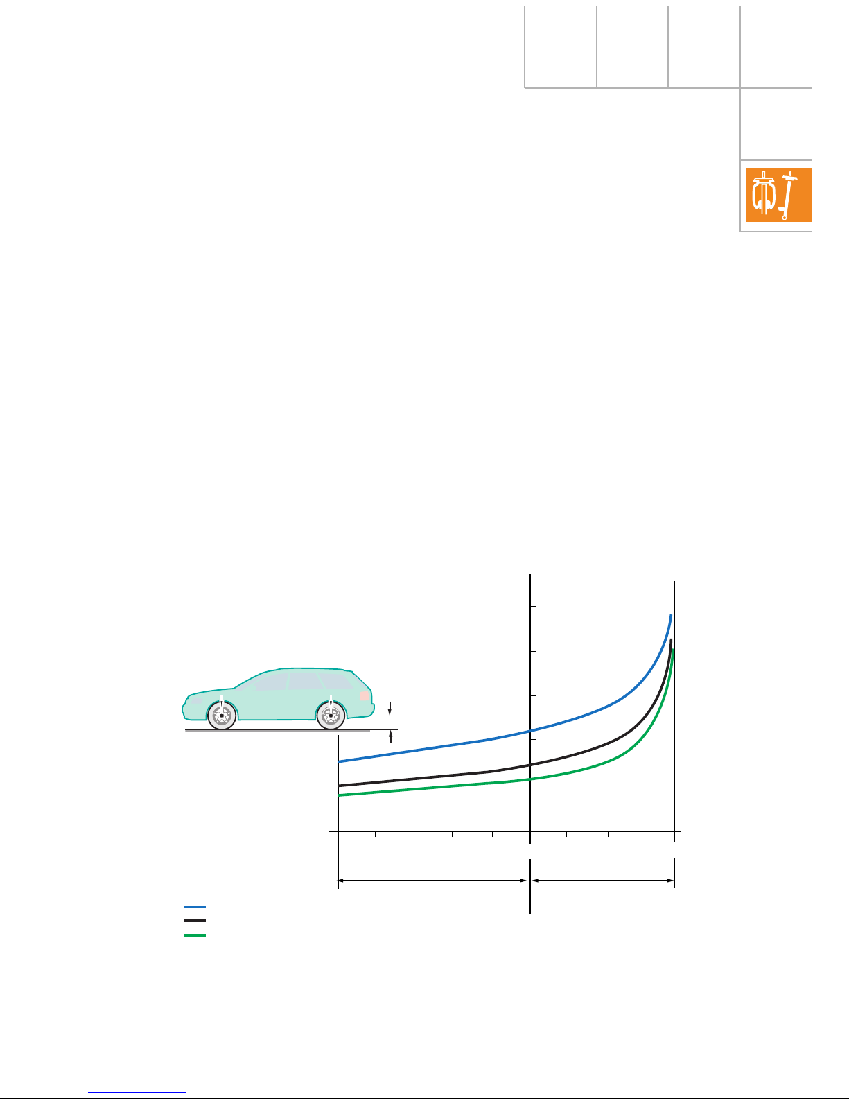
With the aid of self-levelling, the vehicle
(sprung masses) remains at one level (design
position) because the air spring pressure is
adapted accordingly.
Static compression is thus the same at all
times thanks to the self-levelling system and
need not be accounted for when designing
the wheel clearances.
s
stat
= 0
Another feature of self-levelling air
suspension is that the natural frequency of
the bodywork is kept virtually constant
between un-laden and full-load (see chapter
“Air spring characteristic values” page 21).
242_077
H = constant
fully laden
Design position H
un-laden
s
stat
0
Supporting force in kN.
10
8
6
+80 mm+40 mm-40 mm-80 mm
4
2
Air suspension
dyn. rebound dyn. compression
Spring travel
Characteristic curves
of springs
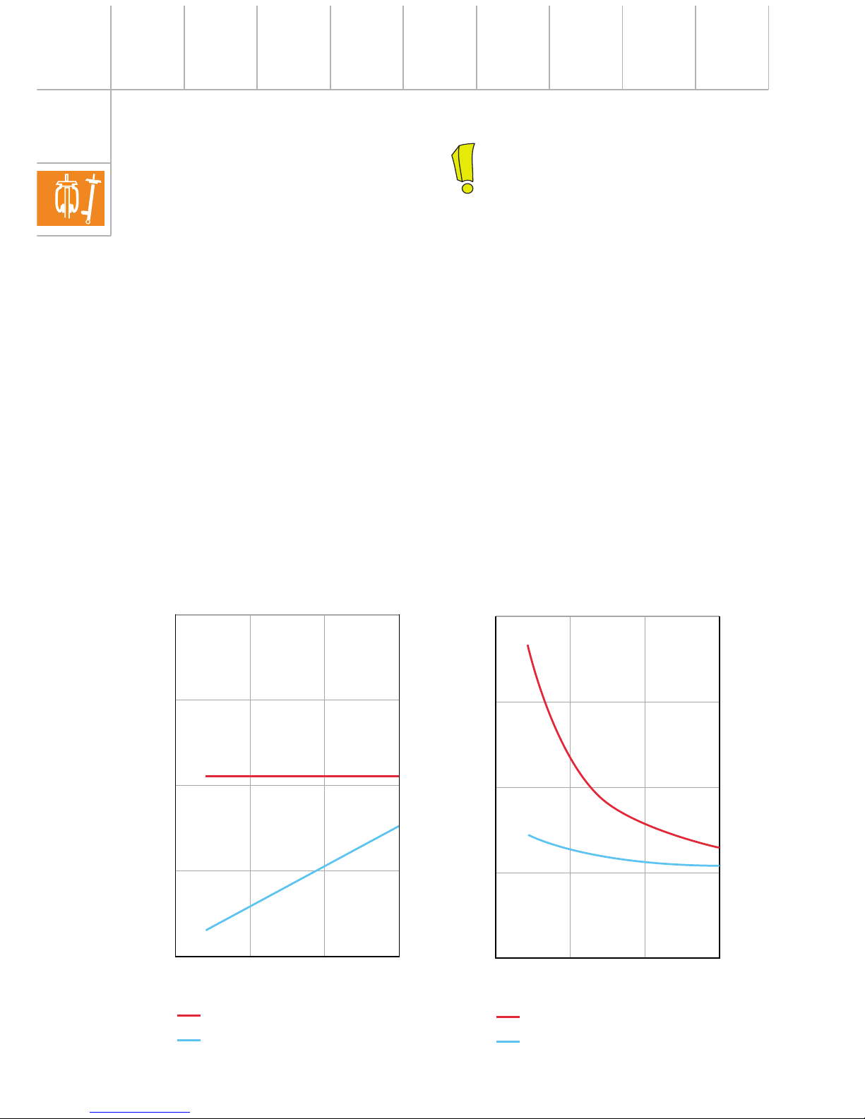
18
Principles of air suspension
Another benefit is the principle-related
progressive characteristic curve of an air
spring.
With fully supporting air suspension on both
axles (Audi allroad quattro), different vehicle
levels can be set, e.g.:
• Normal driving position for city driving.
• Lowered driving position for high speeds
to improve driving dynamics and air
resistance.
• Raised driving position for travel off-road
and on poor road surfaces.
You can find further details in SSP 243
“4-Level air suspension in the Audi allroad
quattro”.
Fully supporting means:
Self-levelling systems are often
combined with steel or gas-filled spring
devices with hydraulic or pneumatic
control. The supporting force of these
systems results from the sum of both
systems. We therefore call them
“partially supporting” (Audi 100/
Audi A8).
In the self-levelling suspension systems
in the Audi A6 (on the rear axle) and in
the Audi allroad quattro (rear and front
axles) air springs are the only
supporting suspension elements and
these systems are therefore described
as “fully supporting”.
0
1
2
3
4
0 102030
242_030
Spring rate
0
1
2
3
4
0 102030
Natural frequency of the bodywork
Supporting force
242_031
Supporting force
Steel springs (linear)
Air springs
Steel springs (linear)
Air springs
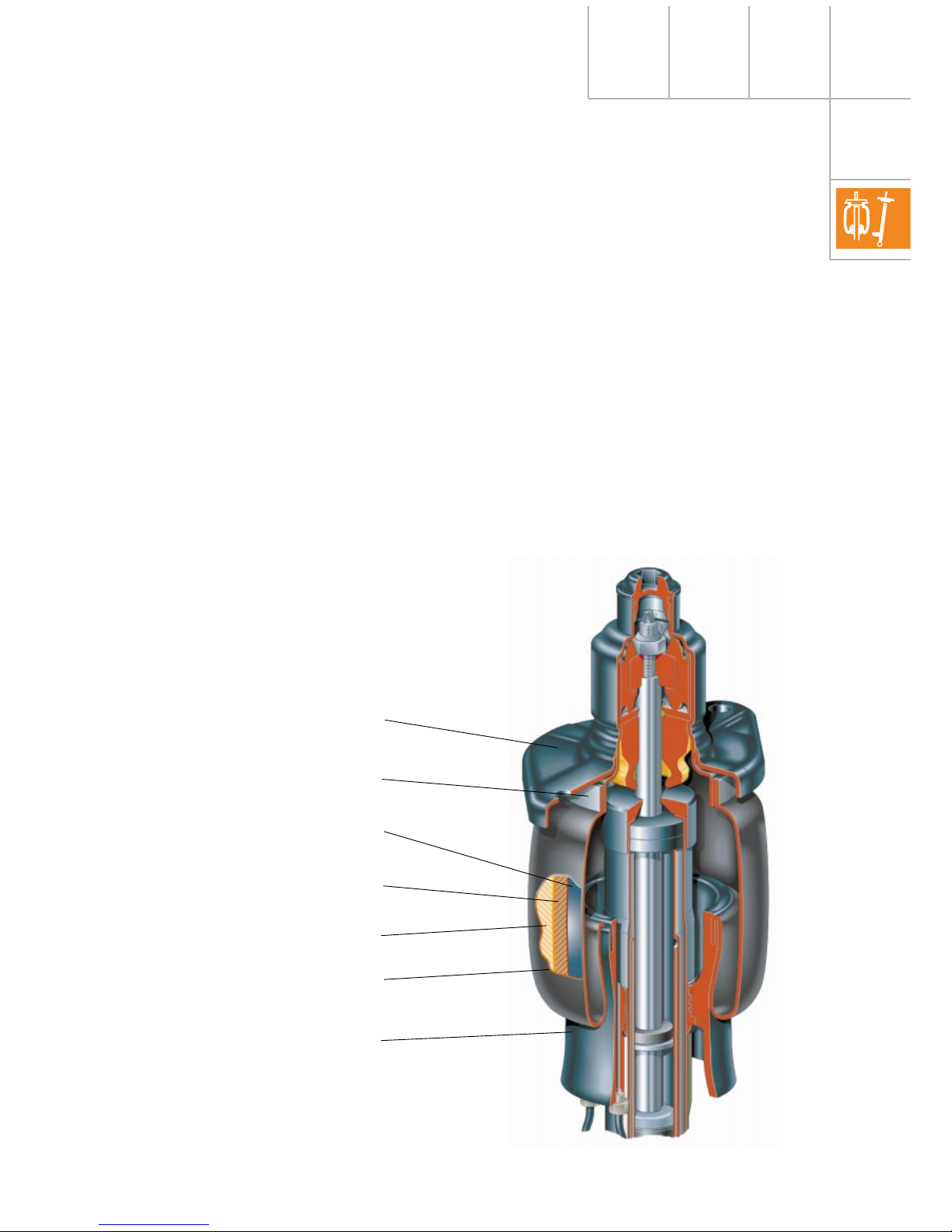
19
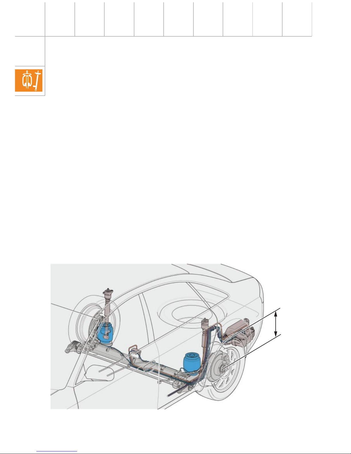
Design of the air springs:
In passenger vehicles, air springs with
U-bellows are used as suspension elements.
These allow greater spring travel in restricted
spaces.
The air springs consist of:
• Upper housing closure
• U-bellows
• Piston (lower housing closure)
• Retaining rings
The construction of the U-bellows can be
seen in fig. 242_032.
242_032
The outer and inner surfaces are made of an
elastomer material. The material is resistant
to all weather influences and is largely oilresistant. The inner surface finish is designed
to be particularly air-tight.
The stability supports absorb the forces
produced by the internal pressure in the air
springs.
Upper housing closure
Retaining ring
Internal surface coating
Woven insert 1
Woven insert 2
External surface coating
Piston
Coaxial arrangement of the air springs
20
Principles of air suspension
High-quality elastomer material and
polyamide cord woven inserts (stability
supports) provide the U-bellows with good
unrolling characteristics and a sensitive
response of the spring system.
The necessary properties are ensured over a
wide temperature range between
-35 °C and +90 °C.
Metal retaining rings tension the U-bellows
between the upper housing closure and the
piston. The retaining rings are machinepressed by the manufacturer.
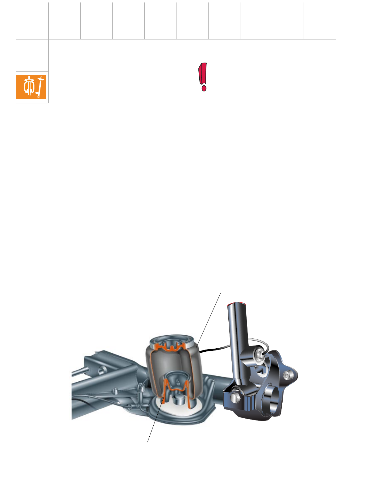
The U-bellows unrolls onto the piston.
Depending on the axle design, the air springs
are either separate from the shock absorbers
or combined as a suspension strut (coaxial
arrangement).
Air springs must not be moved in an
unpressurised condition since the air
bellows cannot unroll on the piston and
would be damaged.
In a vehicle in which the air springs are
unpressurised, the relevant air springs
must be filled with the aid of the
diagnostic tester (see Workshop
Manual) before raising or lowering the
vehicle (e.g. vehicle lifting platform or
vehicle jack).
242_042
Separate arrangement of the air springs
Piston
Air springs
 Loading...