

Page 1
Quick start guide
1856
Speakerphone/
answering system with
caller ID/call waiting
Page 2
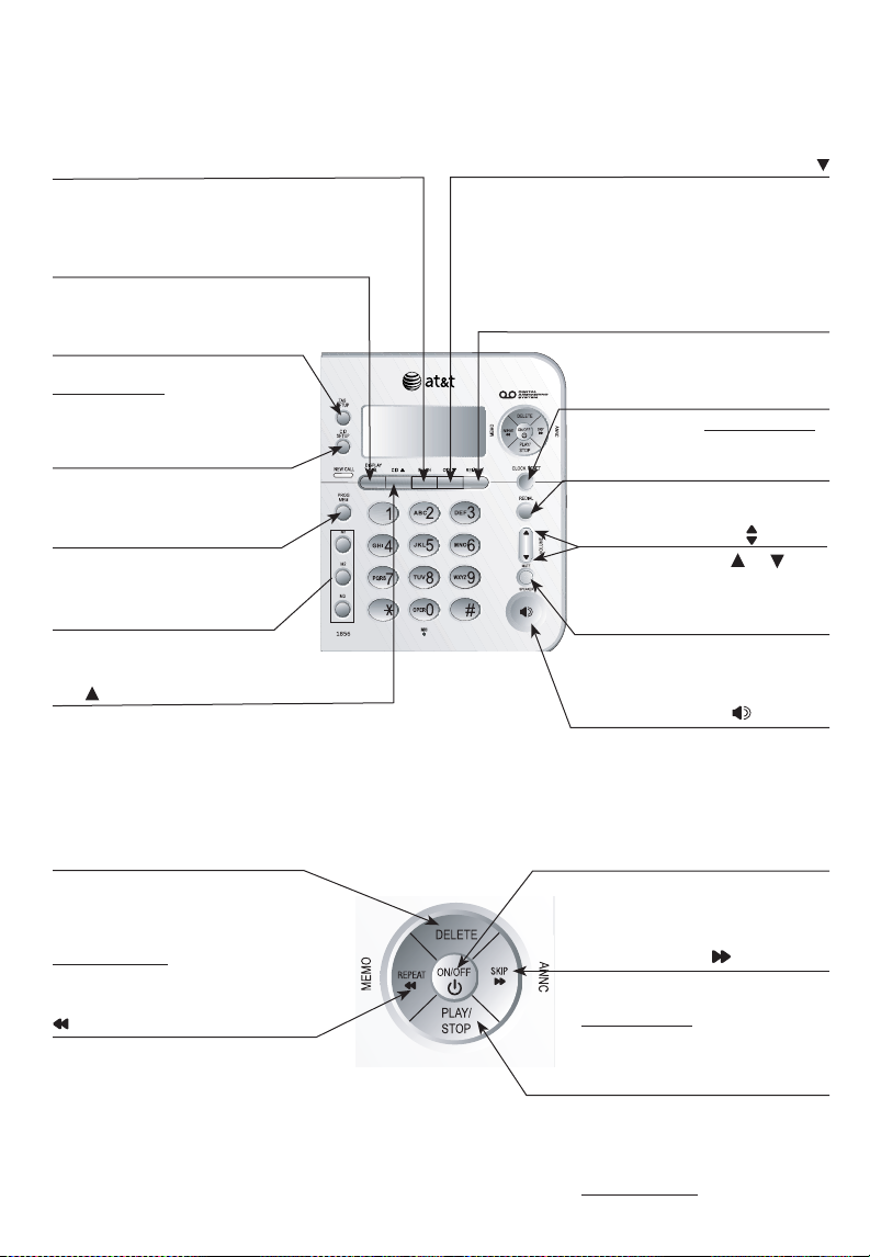
Quick reference guide
FLASH
During a call, press to receive
an incoming call if call waiting is
activated.
DISPLAY DIAL
Press to dial the number
currently displayed.
TAS/SETUP
Press to hear setup options.
Press and hold to change
answering system options.
CID/SETUP
Press to customize the
telephone's operation.
PROG/MEM
Press to program a number.
M1/M2/M3
Press to dial a one-touch
number.
CID
When the telephone is idle,
press to display caller ID
information.
While entering numbers, press
to delete the last number
entered.
CID
When the telephone is idle,
press to display caller ID
information.
While entering numbers, press
twice to insert a three-second
dialing pause.
REMOVE
Press to delete caller ID currently
displayed.
CLOCK RESET
Press to review. Press and hold
to set the clock.
REDIAL
Press to redial last number
dialed.
VOLUME
During a call, press or to
adjust listening volume.
MUTE
Press to silence the microphone.
Press again to resume
conversation.
SPEAKER
Press to turn the speakerphone
on or off (begin or end a call).
DELETE
Press to delete a message
currently playing.
When phone is not in use,
press and hold to delete all old
messages.
REPEAT/MEMO
Press once to repeat a message
currently playing, and press
twice to listen to the previous
messages.
Press to record a memo or
change a menu setting.
ON/OFF
Press to turn answering system
on or off.
SKIP/ANNC
Press to skip a message
or change a menu setting.
Press and hold to record an
announcement.
PLAY/STOP
When the telephone is idle, if
you have new messages, press
to play. Press again to stop message playback.
Press and hold to play all mes-
1
sages (the oldest first)
Page 3

Telephone base installation
4
5
2
1
3
Install the telephone as shown below. Choose a location where the telephone
is not exposed to excessive heat, cold, dust or moisture.
If you subscribe to high-speed Internet service (digital subscriber line - DSL)
through your telephone lines, you must install a DSL filter between the
telephone base and the telephone wall jack. The filter prevents noise and
caller ID problems caused by DSL interference. Please contact your DSL
service provider for more information about DSL filters.
1. Plug one end of the telephone
line cord into the telephone
jack at the back of the
telephone.
2. The small end of the power
adapter has been plugged into
the power jack in the back of
the telephone at the factory.
Double check that it has been
plugged in firmly.
3. Route the cord through the
slot as shown to the right.
4. Plug the other end of the
telephone line cord into a
telephone jack.
5. Plug the large end of the
power adapter into an
electrical outlet not controlled
by a wall switch.
DSL filter (not included)
for DSL users.
Telephone line cord
NOTES:
1. Use only the power adapter supplied with this product or equivalent. To order a
replacement power adapter, visit our website at www.telephones.att.com,
or call 1 (800) 222-3111. In Canada, dial 1 (866) 288-4268.
2. Be sure to use an electrical outlet not controlled by a wall switch.
3. The power adapters are intended to be correctly oriented in a vertical or floor
mount position. The prongs are not designed to hold the plug in place if it is
plugged into a ceiling or under-the-table/cabinet outlet.
2
Page 4

Getting started
Installation options
NOTE: The mounting bracket must be used for both tabletop use and wall
mounting positions.
Tabletop mount
Telephone outlet mounting
plate with mounting studs.
Wall mount
Wall mounting
The telephone base comes with the bracket mounted for tabletop use. If wall
mounting is desired, a telephone outlet wall mounting plate with mounting studs is
required. This mounting plate with studs may be available for purchase from many
hardware or consumer electronics retailers and may require professional installation.
1. To remove the bracket, hold the
telephone base in both hands, press
the two bracket tabs and lift the
bracket away from slots and .
2. Rotate the bracket to the wall mount
ing position, insert the tabs of the
bracket into slots and on the
telephone base, then press the other
bracket tabs into slots and as
shown below.
-
3
Page 5

Installation options
3. Connect the telephone line cord and
power adapter to the jacks on the back of
the telephone base. Bundle the telephone
line cord, and secure it with a twist tie
before placing it inside the bracket. Please
see the picture on the right.
4. Plug the power adapter into an electrical
outlet not controlled by a wall switch. Plug
the telephone line cord into a telephone
wall jack. To mount the telephone on the
wall, position the mounting holes and
over the telephone outlet mounting studs.
Press and slide the bracket down firmly
so the telephone is held securely on the
telephone outlet mounting studs.
Tabletop installation
To return the bracket from the wall mounting to tabletop position, follow the
directions below.
1. Remove the telephone base from the
wall. Unplug the cords from the wall
jacks. Remove the bracket from the
telephone base.
2. Rotate the bracket to tabletop
position, insert the bracket tabs
into slots and
phone base, then press the other
bracket tabs into slots and
Place the bundled telephone
line cord inside the bracket.
on the tele-
.
3. Route cords through slots. Plug the
other end of the telephone line cord
into a telephone wall jack. Plug the
large end of the power adapter into
an electrical outlet not controlled by
a wall switch.
4
Page 6

www.telephones.att.com
© 2008-2009 Advanced American Telephones. All Rights Reserved.
AT&T and the AT&T logo are trademarks of AT&T Intellectual Property licensed to
Advanced American Telephones, San Antonio, TX 78219.
Printed in China. Issue 7 AT&T 09/09.
 Loading...