

Page 1
查询TK5530 供应商
Features
• Identification transponder in plastic cube
• Basic component: e5530 IDIC
• Includes coil and capacitor for tuned circuit antenna
• Adjusted to 125 kHz carrier frequency
Application
• Car immobilizer
• Access control
• Alarm syst ems
• Other identification systems
Description
The TK5530 is a complete transponder, which implements all important functions for
immobilizer and identification systems. It consists of a plastic cube which accommodates the read-only IDIC
identifying data are stored in a 128 bit PROM on the e5530, realized as an array of
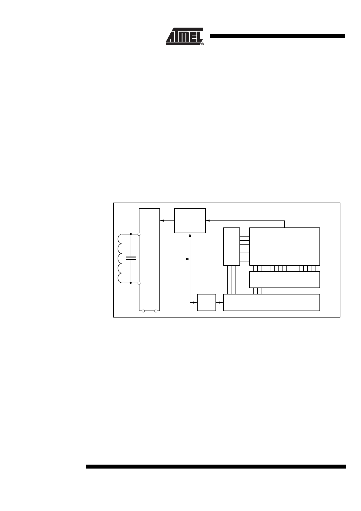
laser-programmable fuses. The logic block diagram for the e5530 is shown in figure 2.
The data are sent bit-serially as a code.
*)
e5530 and the antenna is realized by a LC-circuit.The
Read-Only
Transponder
TK5530
Any attempt to fake the base station wi th a wrong t ransponder will be recognized
immediately.
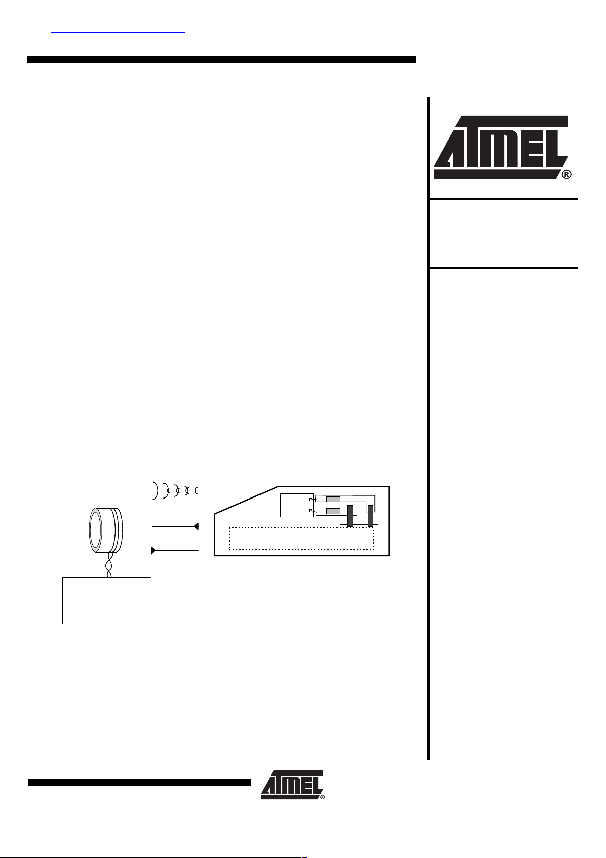
System Block Diagram
Figure 1.
TK5530 Transponder
RF field
Power
Data
Base station
U2270B reader IC
MARC4 series µC
(e5530 + coil + C in plastic cube)
C
e5530
Coil
*)
IDIC stands for IDentification Integrated Circuit and is a trademark of Atmel.
Rev. A5, 19-Dec-01
1 (10)
Page 2
General The transponder consists of a plastic cube which accommodates following components:
• Read-only IDIC
• Antenna realized as tuned LC-circuit
with ROM (e5530)
Read-Only IDIC
with ROM (e5530)
The e5530 is part of a closed coupled id entification s ystem (see fig ure 1). It receiv es
power from a RF tr ansmitter (r eader) whic h is coupled inductively to the IDIC. Th e
TK5530 transp onder oper ates at a nomin al frequenc y of 125 kHz. Receiving RF , the
IDIC responds with a data stream by damping the incoming RF via an internal load. This
damping in turn can be detected by the reader . The iden tif yi ng data are st ored in a 128bit PROM on the e5530, which is factory programmed with a unique code (see specification of the e5530).
The e5530 has several possible options regarding modulation, bitrate, memory size etc.
Antenna The antenna consists of a coil and a capacitor for tuning the circuit to the nominal carrier
frequency of 125 kHz. The coil has a ferrite-core for improving the readout distance.
Figure 2.
Analog front end
Modulator
Coil
Load
Clock
extractor
Mod
Clk
FSK
PSK
BIPH
Manchester
r
e
d
o
c
e
d
w
o
R
Data
R7
R6
R5
R4
R3
R2
R1
R0
128 bit PROM
Coil
Rectifier
V
DD
VSS
Bitrate
3
2
5
4
1
0
1
1
1
1
1
1
6
5
7
8
9
C
C
C
C
C
C
C
Column decoder
4
6
2
0
1
A
A
A
5
3
A
A
A
A
Counter
4
3
1
2
C
C
C
C
0
C
C
C
C
C
2 (10)
TK5530
Rev. A5, 19-Dec-01
Page 3
TK5530
Absolute Maximum Ratings
Parameter Symbol Value Unit
Operating temperature range T
Storage temperature range T
Assembly temperature t < 5 min T
Magnetic field strength at 125 kHz H
amb
stg
ass
pp
Operating Characteristics Transponder
T
= 25°C, f = 125 kHz unless otherwise specified
amb
Parameters Test Conditions Symbol Min. Typ. Max. Unit
Inductance L3.95mH
LC circuit, H
Resonance frequency Room temperature f
Resonance frequency T
Quality factor Q
Magnetic Field Strength (H)
Max. field strength where tag does
not modulate
Field strength for operation T
Field strength for operation T
Field strength for operation T
Maximun field strength H
Modulation Range (see also H-DV curve)
Modulation range H
pp = 20 A/m
= -40 to +85°Cf
amb
No influence to other tags in the field H
= -40°CH
amb
= 25°CH
amb
= 85°CH
amb
= 20 A/m
pp
= 30 A/m
H
pp
H
= 50 A/m
pp
= 100 A/m
H
pp
-40 to +85 °C
-40 to +125 °C
170 °C
1000 A/m
r
r
LC
pp not
pp -40
pp 25
pp 85
pp max
121.4 125 129.2 kHz
120.0 131.0 kHz
13
2A/m
30 A/m
18 A/m
17 A/m
DV 4.0
6.0
8.0
8.0
600 A/m
V
Rev. A5, 19-Dec-01
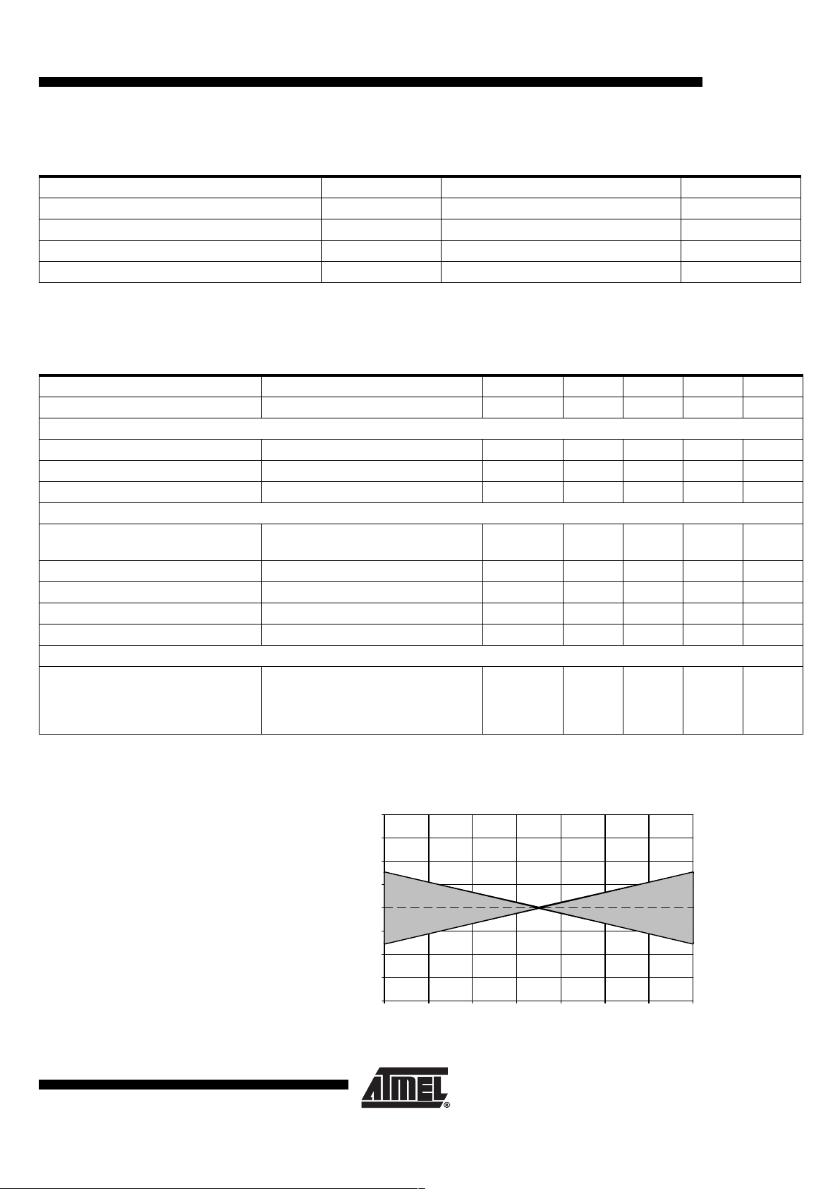
Figure 3. Typical TK-range of resonance frequency
4
3
2
1
( % )
0
res
-1
TK of f
-2
-3
-4
-40.0 -20.0 0.0 20.0 40.0 60.0 80.0 100.0
Temperature ( °C )
3 (10)
Page 4

Figure 4. Typical H-DV curve
9
8
7
6
5
4
DV ( V )
3
2
1
0
0.0 20.0 40.0 60.0 80.0 100.0 120.0
Figure 5. Measurement of the modulation range DV
Output voltage of the testing application (see figure 6 and 7)
HPP ( Á/m )
VmodV1
DV = V1-Vmod
4 (10)
TK5530
Rev. A5, 19-Dec-01
Page 5

TK5530
L
FIELD GENERATING COIL
Measurement
Assembly
All parameters a re m easured in a Hel mholt z-ar rangem ent, w hic h ge nerates a ho mogenous magnetic field (see figure 6 and 7). A function generator drives the field generating
coils, so the magnetic field can be varied in frequency and field strength.
Figure 6. Testing application
SENSING COILS ( IN PHASE )
OUTPUT
VOLTAGE
REFERENCE COIL
( IN PHASE )
TK5530
FIELD GENERATING
COILS ( IN PHASE )
FUNCTION
GENERATOR
SUBTRACTOR
REFERENCE COIL ( IN PHASE )
AMPLIFIER
1:10
Figure 7. Testing geometry
l = 30 mm
22 mm
REFERENCE COIL
SENSING COIL
5 mm
FIELD GENERATING COI
Transponder
d = 60 mm
REFERENCE COIL
SENSING COIL
Rev. A5, 19-Dec-01
5 (10)
Page 6

IDIC (Reference Data
Sheet e5530)
Memory size maximum 128 Bit (details see “Coding”)
Memory type ROM
Programming Laser cutting
Data rate RF/32 - RF/64
Encoding Manchester or Bi-phase
Modulation AM
Maximum coil voltage
(internally limited) V
(I = 5 mA) 16 V
pp
Coding The memory of the TK5530 can be selected to be a 64- or 128-bit rolli ng code. In the
non-standard version, the first 8 bits ar e a customer-specific pattern . This can be
selected by the customer, provided that Atmel agrees to the customer’s proposal. This
pattern is unique within the serial rolling code data stream. The ID code and further bit
informations foll owing the 8-bit header can al so be defined within the cu stomer’s
specification.
The set-up of a suitable coding scheme can be provided on customer’s request.
Read Distance The maximum distance between the base station and the TK5530 mainly depends on
the base station, the coil geometries and the modulation options chosen (see U2270B
Antenna Design Hints and t he U227 0B dat a shee t). Wh en gen erating an app ropriat e
field with a suitable reader technique, a distance of 10 cm and more can be obtained.
When using the Atmel U2270B dem o board, the ty pical distances in the rang e of 0 to
5 cm can be achieved. Maximum distance values which are generally valid can not be
given in this da ta shee t. The exa ct measu ring o f the max imum di stance s hould be carried out with the TK5530 being integrated into the specific application.
Orderi ng Information
Extended Type
Number
TK5530HM-232-PP Manch. RF/32 64 bit no
TK5530HM-zzz-PP defined by customer > 300 kpcs p.a.
Note: 1) Definition of customized part number basing on orders for first year volume (300 kpcs)
2) Definition of header, ID code, checksum etc. according to customers data base
3) 8.000 US$ initial cost for metal mask
4) Lead time 5 month
5) Low volume customized application can be covered by TK5550F-PP programming,
for identical application, as TK5530H-zzz-PP.
6 (10)
TK5530
Modul. Data
Rate
Con-
figuration
Check-
sum
check-
sum
Header ID
Code
E6 fixed and
unique
code
SPQ
(Minimum
Volume)
10 kpcs >1 kpcs
Minimum
Order Volume
(per order,
from stock)
Rev. A5, 19-Dec-01
Page 7

Ordering number for standard version: TK5530HM-232-PP
Ordering number for customized version:
TK5530xy-zzz-PP
Plastic package
Custom code
Modulation
M -> Manchester code
B -> Biphase code
Mask version of die
Application
Figure 8. Complete transponder system with the read/write base-station IC U2270B
TK5530
5 V
C31
470 kΩ
47 nF
1.5 nF
22 µF
680 pF
4.7 kΩ
1N4148
1.2 nF
1.35 mH
r
e
w
o
P
e5530
Transponder
TK5530
110 kΩ
V
V
Batt
DV
Input
COIL2
R
COIL1
a
t
a
D
DGND GND
EXTVS
U2270B
S
RF
MS
CFE
OE
Standby
Output
Gain
Read/write
circuit
f
= 1 / (2π√LC) = 125 kHz
res
BP00
BP01
BP02
BP03
BP10
100 nF
5 V
V
DD
M44C260
osc IN
osc OUT
Micro
controller
V
SS
32 kHz
Rev. A5, 19-Dec-01
7 (10)
Page 8

Package Information
Dimensions in mm
8 (10)
TK5530
Rev. A5, 19-Dec-01
Page 9

TK5530
Ozone Depleting Substances Policy Statement
It is the policy of Atmel Germany GmbH to
1. Meet all present and future national and international statutory requirements.
2. Regularly and continuously improve the performance of our products, processes, distribution and operating systems
with respect to their impact on the health and safety of our employees and the public, as well as their impact on
the environment.
It is particular concer n to control or eliminate rele ases of those s ubstances into the atm osphere which are known as
ozone depleting substances (ODSs).
The Montreal Protocol (1987) and its London Amendments (1990) intend to severely restrict the use of ODSs and forbid
their use within the next ten years. Various national and inter n ational initi atives are pres sing for an ear lier ban on these
substances.
Atmel Germany GmbH has been able to use its policy of continuous improvements to eliminate the use of ODSs listed
in the following documents.
1. Annex A, B and list of transitional substances of the Montreal Protocol and the London Amendments respectively
2. Class I and II ozone depleting substances in the Clean Air Act Amendments of 1990 by the Environmental
Protection Agency (EPA) in the USA
3. Council Decision 88/540/EEC and 91/690/EEC Annex A, B and C (transitional substances) respectively.
Atmel Germany GmbH can certify that our semiconductors are not manufactured with ozone depleting substances and
do not contain such substances.
Rev. A5, 19-Dec-01
9 (10)
Page 10

Atmel Sales Offices
France
3, Avenue du Centre
78054 St.-Quentin-en-Yvelines
Cedex
Tel: +33 1 30 60 70 00
Fax: +33 1 30 60 71 11
Germany
Erfurter Strasse 31
85386 Eching
Tel: +49 89 319 7 0 0
Fax: +49 89 319 46 21
Kruppstrasse 6
45128 Essen
Tel: +49 201 247 30 0
Fax: +49 201 247 30 47
Theresienstrasse 2
74072 Heilbronn
Tel: +49 7131 67 36 36
Fax: +49 7131 67 31 63
Italy
Via Grosio, 10/8
20151 Milano
Tel: +39 02 38 03 71
Fax: +39 02 38 03 72 34
Spain
Principe de Vergara, 112
28002 Madrid
Tel: +34 91 564 5 1 81
Fax: +34 91 562 75 14
Sweden
Kavallerivaegen 24, Rissne
17402 Sundbyberg
Tel: +46 8 587 48 800
Fax: +46 8 587 48 850
United Kingdom
Easthampstead Road
Bracknell
Berkshire RG12 1LX
Tel: +44 1344 707 300
Fax: +44 1344 427 371
USA Western
2325 Orchard Parkway
San Jose, California 95131
Tel: +1 408 441 0311
Fax: +1 408 436 4200
USA Eastern
1465 Route 31, Fifth floor
Annandale
New Jersey 08801
Tel: +1 908 848 5208
Fax: +1 908 848 5232
Hong Kong
Room #1219,
Chinachem Golden Plaza
77 Mody Road, Tsimhatsui East
East Kowloon, Hong Kong
Tel: +852 23 789 789
Fax: +852 23 755 733
Korea
25-4, Yoido- Dong, Suit e 605,
Singsong B ldg.
Youngdeungpo-Ku
150-010 Seoul
Tel: +822 785 1136
Fax: +822 785 1137
Rep. of Singapore
Keppel Building #03-00
25 Tampines Street 92,
Singapore 528877
Tel: +65 260 8223
Fax: +65 787 9819
Taiwan, R.O.C.
8F-2, 266 Sec. 1 Wen Hwa 2 Rd.
Lin Kou Hsiang,
244 Taipei Hsien
Tel: +886 2 2609 5581
Fax: +886 2 2600 2735
Japan
Tonetsushinkawa Bldg.
1-24-8 Shinkawa Chuo Ku
Tokyo 104-0033
Tel: +81 3 3523 3551
Fax: +81 3 3523 7581
Web Site
http://www.atmel-wm.com
© Atmel Germa ny GmbH 2001 .
Atmel Germany GmbH makes no warranty for the use of its products, other than those expressly contained in the Company’s standard warranty
which is detailed in Atmel Germany GmbH’s Terms and Conditions. The Company assumes no responsibility for any errors which may appear in
this document, reserves the right to change devices or specifications detailed herein at any time without notice, and does not make any commi tment to update the information contained herein. No licenses to patents or other intellectual proper ty of Atmel Ger many GmbH are granted by
the Company in connection with the sale of Atmel Germany GmbH products, expressly or by implication. Atmel Germany GmbH’s products are
not authorized for use as critical components in life s uppor t devices or systems.
Data sheets can also be retrieved from the Internet: http://www.atmel-w m.com
Rev. A5, 19-Dec-01
 Loading...