

Page 1
TK15421
75 Ω VIDEO LINE DRIVER
FEATURES
■ Fixed Gain (6 dB)
■ Internal 75 Ω Drivers
■ Very Small Output Capacitor at SAG Function Pin
■ Active High ON/OFF Control
■ Very Low Standby Current (typ. I
≤ 25 µA)
CCS
■ Internal Summing Circuit of Y/C Signal.
DESCRIPTION
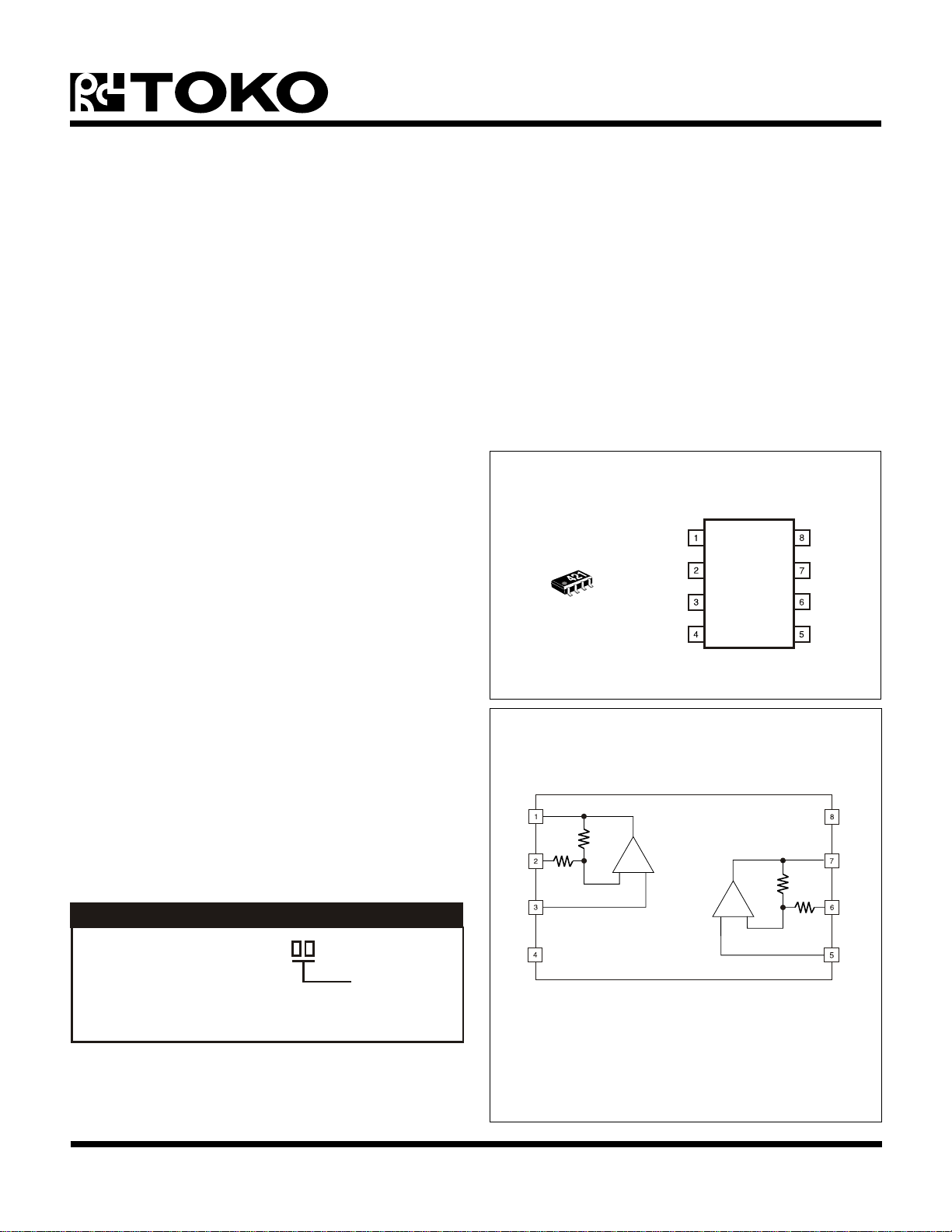
The TK15421M is a 75 Ω video line driver IC which
contains 2 channeld. The voltage gain is 6 dB.
It is suitable for replacement of Motorola’s video line driver
IC MC14576CF.
The TK15421M is available in the SOP-8 surface mount
package.
APPLICATIONS
■ Video Equipment
■ Digital Cameras
■ CCD Cameras
■ TV Monitors
■ Video Tape Recorders
■ LCD Televisions
TK15421
OUTPUT A
-INPUT A
+INPUT A
V
CC
OUTPUT B
-INPUT B
V
EE
+INPUT B
BLOCK DIAGRAM
500 Ω
+
500 Ω
ORDERING INFORMATION
-
500 Ω
+
-
500 Ω
TK15421M
Tape/Reel Code
TAPE/REEL CODE
TL: Tape Left
August 1999 TOKO, Inc. Page 1
Page 2
TK15421
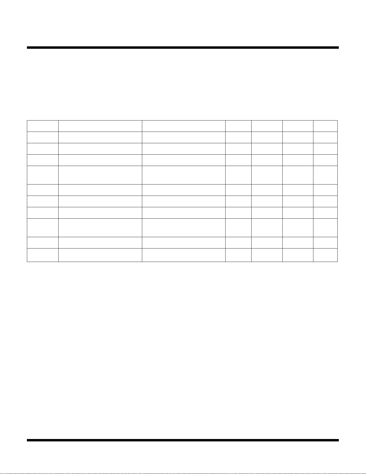
ABSOLUTE MAXIMUM RATINGS
Supply Voltage ......................................................... 14 V
Operating Voltage Range............................ 4.0 to 12.0 V
Power Dissipation (Note 1) ................................ 400 mW
Storage Temperature Range ................... -55 to +150 °C
Operating Temperature Range ...................-25 to +85 °C
Input Frequency .................................................. 20 MHz
TK15408M ELECTRICAL CHARACTERISTICS
Test conditions: V
LOBMYSRETEMARAPSNOITIDNOCTSETNIMPYTXAMSTINU
I
CC
AVGniaGegatloVf
rfesnopseRycneuqerFf
V
PPO
GDniaGlaitnereffiDV
PDesahPlaitnereffiDV
TCklaTssorCf
RRVS
C
NI
= 5.0 V, VEE = -5.0 V, TA = 25 °C unless otherwise specified.
CC
tnerruCylppuSlangisoN1.810.42Am
ni
ni
egatloVtuptuOmumixaM
gniwS
NI
NI
NI
noitcejeRegatloVylppuS
oitaR
∆ V4.0=V
V,zHM1=
egatlovCD0.57.5V
V1=
P-P
V1=
P-P
P-Pf,NI
V1=
NI
P-P
zHM01/zHM1=5.0-Bd
esacriatS,0.3-3.00.3+%
esacriatS,0.3-4.00.3+ged
V,zHM34.4=
V1=
NI
P-P
ecnaticapaCtupnI 6.8Fp
6.59.52.6Bd
P-P
0.053.67Bd
zHk001=
3.64Bd
Z
NI
Note 1: Power dissipation is 400 mW when mounted as recommended. Derate at 3.2 mW/°C for operation above 25°C.
Note 2: Turn on in order of VEE and VCC when using this IC with two power supplies.
ecnadepmItupnI 0.5
M
Ω
Page 2 August 1999 TOKO, Inc.
Page 3
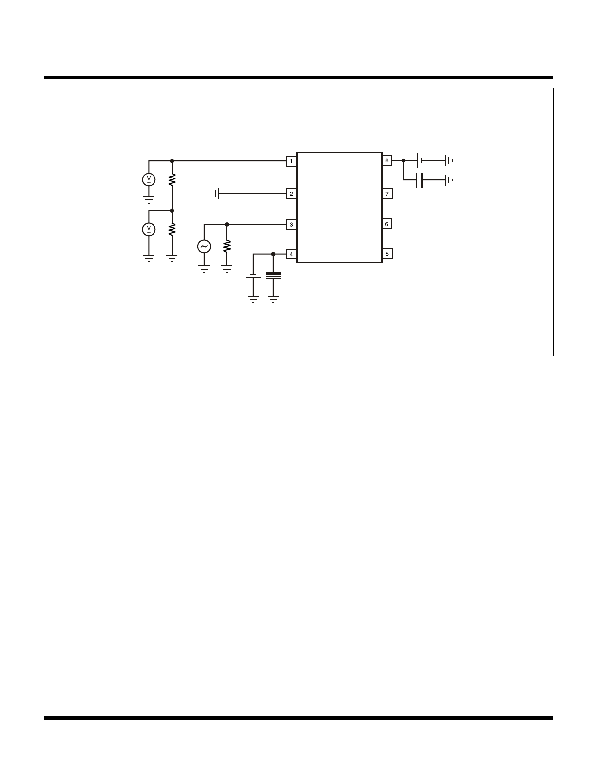
TEST CIRCUIT
TK15421
V
CC
5 V
75 Ω
75 Ω
V
5 V
75 Ω
EE
47 µF
+
+
47 µF
August 1999 TOKO, Inc. Page 3
Page 4
TK15421
)
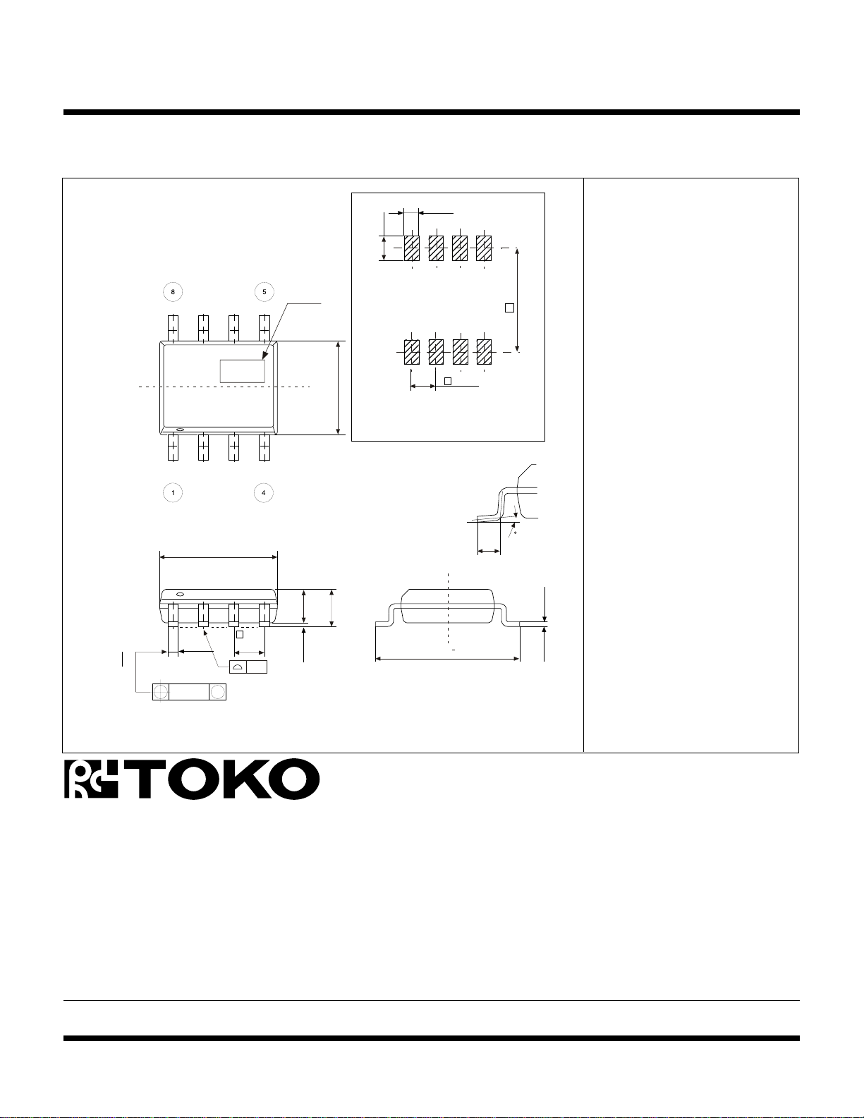
PACKAGE OUTLINE
SOP-8
0.42
+ 0.15
- 0.05
0.76
1.27
Marking Information
Marking
TK15421 421
Mark
e
3.9
Recommended Mount Pad
4.9
1.45
e
1.27
0.1
1.75 max
0 ~ 0.25
1.27
+
0.3
6.0
5.4
1
e
0.5
0 ~ 10
- 0.05
+ 0.15
0.2
0.12
M
Dimensions are shown in millimeters
Tolerance: x.x = ± 0.2 mm (unless otherwise specified
Toko America, Inc. Headquarters
1250 Feehanville Drive, Mount Prospect, Illinois 60056
Tel: (847) 297-0070 Fax: (847) 699-7864
TOKO AMERICA REGIONAL OFFICES
Midwest Regional Office
Toko America, Inc.
1250 Feehanville Drive
Mount Prospect, IL 60056
Tel: (847) 297-0070
Fax: (847) 699-7864
Western Regional Office
Toko America, Inc.
2480 North First Street , Suite 260
San Jose, CA 95131
Tel: (408) 432-8281
Fax: (408) 943-9790
Eastern Regional Office
Toko America, Inc.
107 Mill Plain Road
Danbury, CT 06811
Tel: (203) 748-6871
Fax: (203) 797-1223
Semiconductor Technical Support
Toko Design Center
4755 Forge Road
Colorado Springs, CO 80907
Tel: (719) 528-2200
Fax: (719) 528-2375
Visit our Internet site at http://www.tokoam.com
The information furnished by TOKO, Inc. is believed to be accurate and reliable. However, TOKO reserves the right to make changes or improvements in the design, specification or manufacture of its
products without further notice. TOKO does not assume any liability arising from the application or use of any product or circuit described herein, nor for any infringements of patents or other rights of
third parties which may result from the use of its products. No license is granted by implication or otherwise under any patent or patent rights of TOKO, Inc.
Page 4 August 1999 TOKO, Inc.
 Loading...