

Page 1
Technical Specification
F601
0.25 to 256 in
-40 to +752 °F
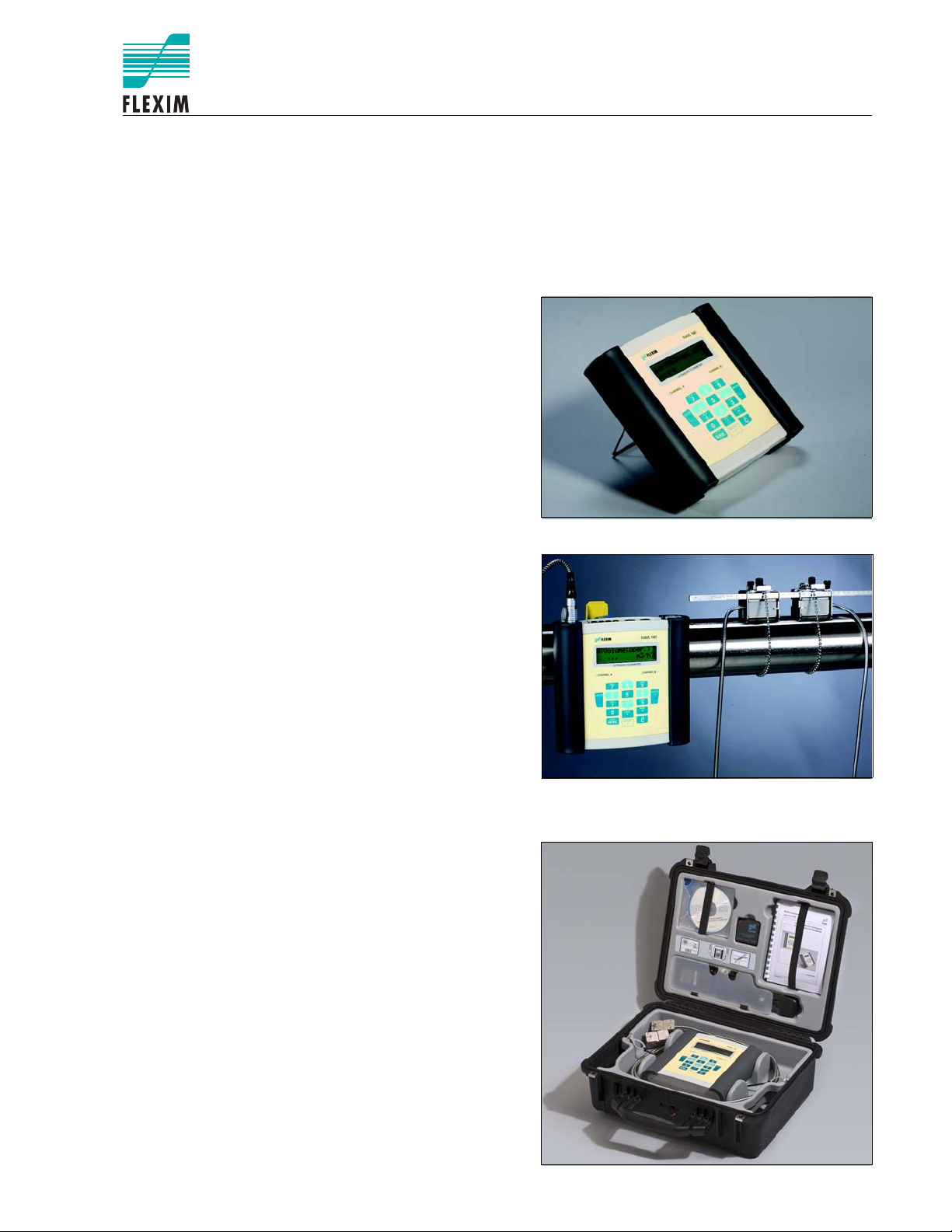
FLUXUS® F601
Portable Ultrasonic Flow Measurement of Liquids
Portable instrument for non-intrusive, quick ultrasonic flow measurement with clamp-on technology for all
types of piping
Features
• Precise bi-directional and highly dynamic flow measurement with the non-intrusive clamp-on technology
• High precision at fast and slow flow rates, high temperature and zero point stability
• Portable, easy-to-use flow transmitter with 2 flow channels, multiple inputs/outputs, an integrated data logger
with a serial interface
• Water and dust-tight (NEMA 4); resistant against oil,
many liquids and dirt
• Li-Ion battery provides up to 14 hours of measurement
operation
• Automatic loading of calibration data and transducer
detection for a fast and easy set-up (less than 5 min),
providing precise and long-term stable results
• User-friendly design
• Transducers available for a wide range of inner pipe
diameters ( ) and fluid temperatures
()
• Probe for wall thickness measurement available
• Robust, water-tight (NEMA 4) transport case with comprehensive accessories
• HybridTrek automatically switches between transit time
and NoiseTrek mode of measurement when high particulate flows are encountered
• QuickFix for fast mounting of the flow transmitter in difficult conditions
FLUXUS supported by handle
Measurement with transducers mounted by mounting frames
and flow transmitter fixed to the pipe by the QuickFix pipe
mounting fixture
Applications
Designed for the following industries:
• Chemical industry
• Water and wastewater industry
• Oil and gas industry
• Cooling systems and air conditioners
• Facility management
• Aviation industry
Measurement equipment in transport case
TSFLUXUS_F601V1-5-1US_Lus, 2014-02-25 1
Page 2

FLUXUS® F601 Technical Specification
Table of Contents
Function ........................................................................................................................................................... 3
Measurement Principle ..................................................................................................................................... 3
Calculation of Volumetric Flow Rate ................................................................................................................. 3
Number of Sound Paths.................................................................................................................................... 4
Typical Measurement Setup ............................................................................................................................. 5
Flow Transmitter ............................................................................................................................................. 6
Technical Data .................................................................................................................................................. 6
Dimensions ....................................................................................................................................................... 8
Standard Scope of Supply ................................................................................................................................ 9
Connection of Adapters................................................................................................................................... 10
Example for the Equipment of a Transport Case ............................................................................................ 11
Transducers................................................................................................................................................... 12
Transducer Selection ...................................................................................................................................... 12
Transducer Order Code .................................................................................................................................. 13
Technical Data ................................................................................................................................................ 14
Transducer Mounting Fixture ...................................................................................................................... 17
Coupling Materials for Transducers............................................................................................................ 21
Connection Systems..................................................................................................................................... 22
Transducer Cable............................................................................................................................................ 22
Clamp-on Temperature Probe (optional) .................................................................................................... 23
Wall Thickness Measurement (optional)..................................................................................................... 24
TSFLUXUS_F601V1-5-1US_Lus, 2014-02-252
Page 3
Technical Specification FLUXUS® F601
t
0
t1t
2
V
·
V
·
Function
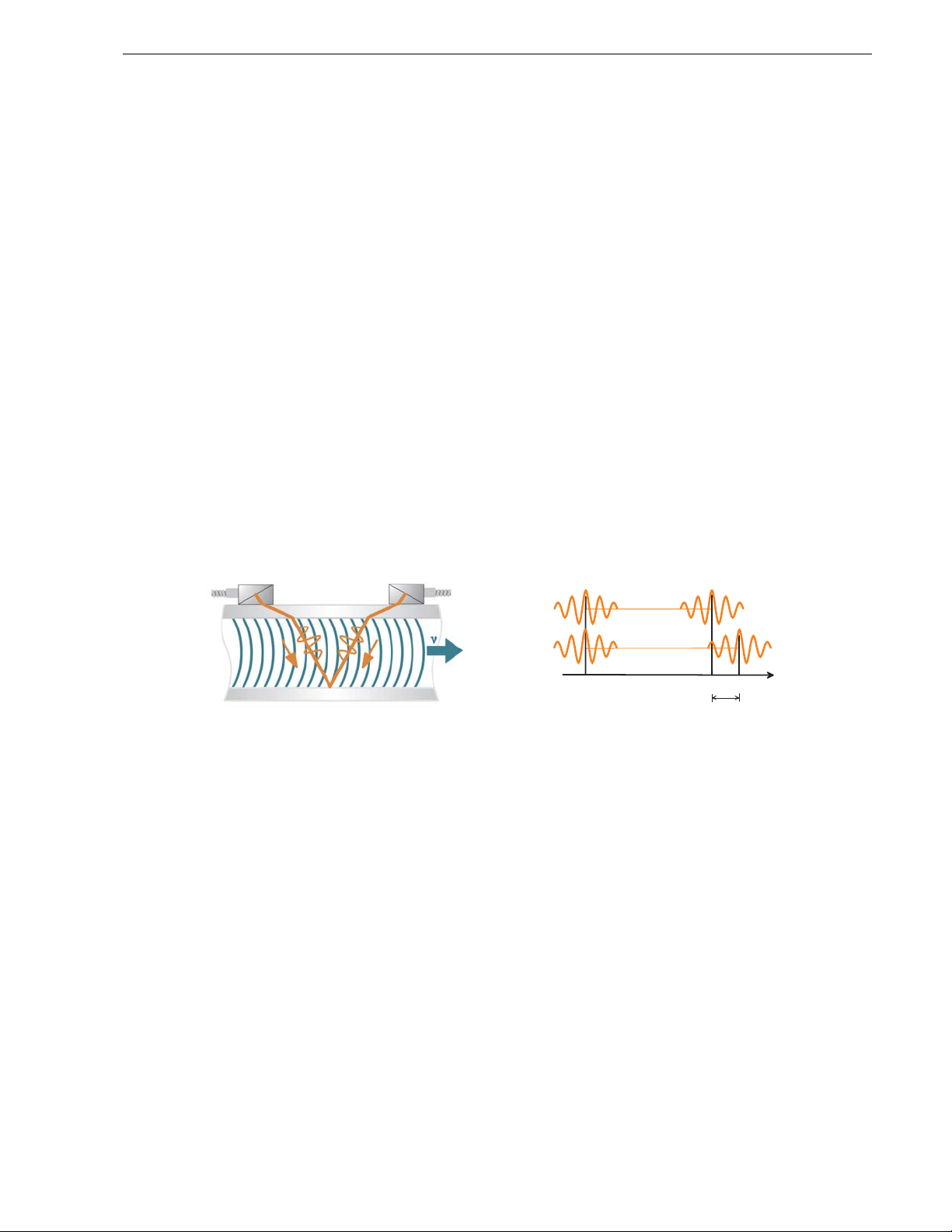
Measurement Principle
Transit Time Difference Principle
In order to measure the flow of a medium in a pipe, ultrasonic signals are used, employing the transit time difference principle. Ultrasonic signals are emitted by a transducer installed on the pipe and received by a second transducer. These signals are emitted alternately in the flow direction and against it.
As the medium in which the signals propagate is flowing, the transit time of the ultrasonic signals in the flow
direction is shorter than against the flow direction.
The transit time difference, ∆t, is measured and allows the flowmeter to determine the average flow velocity
along the propagation path of the ultrasonic signals. A flow profile correction is then performed in order to obtain the area averaged flow velocity, which is proportional to the volumetric flow rate.
Two integrated microprocessors control the entire measuring process. This allows the flowmeter to remove
disturbance signals, and to check each received ultrasonic wave for its validity which reduces noise.
HybridTrek
If the gaseous or solid content in the medium increases occasionally during measurement, a measurement
with the transit time difference principle is no longer possible. NoiseTrek mode will then be selected by the
flowmeter. This measurement method allows the flowmeter to achieve a stable measurement even with high
gaseous or solid content.
The transmitter can switch automatically between transit time and NoiseTrek mode without any changes to
the measurement setup.
Path of the ultrasonic signal Transit time difference ∆t
Calculation of Volumetric Flow Rate
= kRe . A . ka . ∆t/(2 . tfl)
where
= volumetric flow rate
k
= fluid mechanics calibration factor
Re
A = cross-sectional pipe area
k
= acoustical calibration factor
a
∆t = transit time difference
t
= transit time in the medium
fl
TSFLUXUS_F601V1-5-1US_Lus, 2014-02-25 3
Page 4
FLUXUS® F601 Technical Specification
a
a
a > 0
a < 0
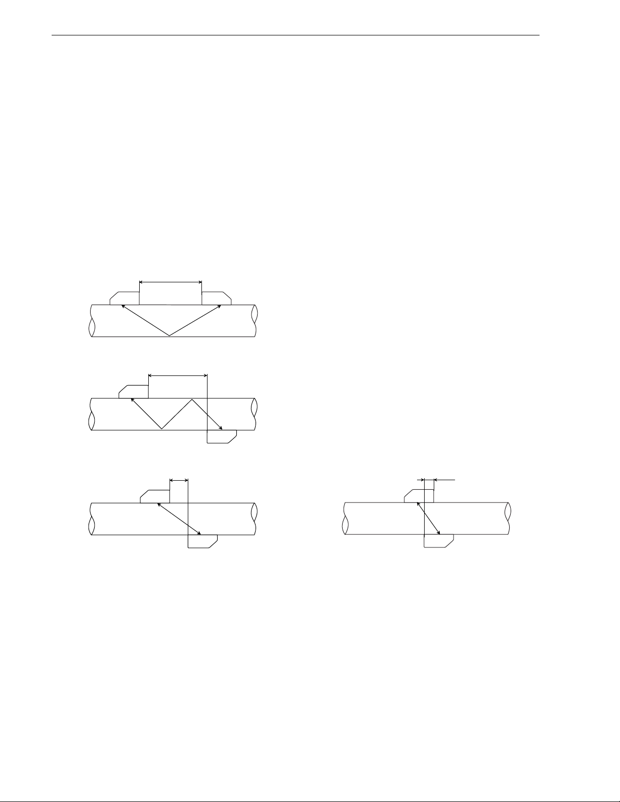
Number of Sound Paths
The number of sound paths is the number of transits of the ultrasonic signal through the medium in the pipe.
Depending on the number of sound paths, the following methods of installation exist:
• reflect arrangement
The number of sound paths is even. Both of the transducers are mounted on the same side of the pipe.
Correct positioning of the transducers is easier.
• diagonal arrangement
The number of sound paths is odd. Both of the transducers are mounted on opposite sides of the pipe.
• direct mode
Diagonal mode with 1 sound path. This should be used in the case of a high signal attenuation by the medium, pipe or coatings.
The preferred method of installation depends on the application. While increasing the number of sound paths
increases the accuracy of the measurement, signal attenuation increases as well. The optimum number of
sound paths for the parameters of the application will be determined automatically by the transmitter.
As the transducers can be mounted with the transducer mounting fixture in reflect arrangement or diagonal arrangement, the number of sound paths can be adjusted optimally for the application.
.
a = transducer distance
Reflect arrangement, number of sound paths: 2
Diagonal arrangement, number of sound paths: 3
Direct mode, number of sound paths: 1 Direct mode, number of sound paths: 1,
negative transducer distance
4 TSFLUXUS_F601V1-5-1US_Lus, 2014-02-25
Page 5
Technical Specification FLUXUS® F601
U L T R A S O N I C F L O W M E T E R
1 3
2
0
4 65
7
8
N E X T
Q
O N
Q -
Q +
M U X
D IS P
Q
O FF
L IG H T
E N T E R
C
O N
C H A N N E L A
C H A N N E L B
9
D IS P
E N T E R
3 x O F F
M O D E
B R K
B A TT E R Y
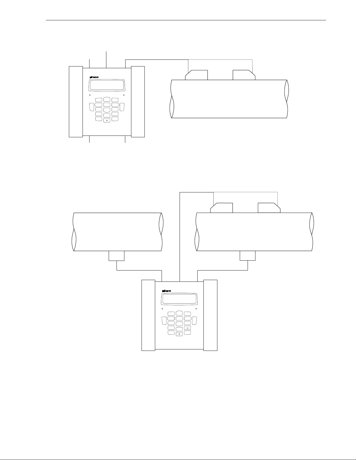
transducers
transmitter
RS232
outputs
inputs
power supply unit/battery charging unit
U L T R A S O N I C F L O W M E T E R
1 3
2
0
4 65
7
8
N E X T
Q
O N
Q -
Q +
M U X
D IS P
Q
O FF
L IG H T
E N T E R
C
O N
C H A N N E L A
C H A N N E L B
9
D IS P
E N T E R
3 x O F F
M O D E
B R K
B A TT E R Y
transducers
transmitter
temperature probe
temperature probe
supply line
return line
volumetric flow rate
supply temperature
return temperature
Typical Measurement Setup
Example of a measurement setup in reflect arrangement
TSFLUXUS_F601V1-5-1US_Lus, 2014-02-25 5
Example of a heat flow measurement
Page 6

FLUXUS® F601 Technical Specification
±1.6 % of reading ±0.03 ft/s
±1.2 % of reading ±0.03 ft/s
Flow Transmitter
Technical Data
FLUXUS F601
design portable
measurement
measurement principle transit time difference correlation principle,
flow velocity 0.03 to 82 ft/s
repeatability 0.15 % of reading ±0.03 ft/s
medium all acoustically conductive liquids with < 10 % gaseous or solid content in volume (transit time difference
temperature compensation corresponding to the recommendations in ANSI/ASME MFC-5.1-2011
accuracy
1
with standard calibration
with advanced calibration
(optional)
with field calibration
2
flow transmitter
power supply 100 to 240 V/50 to 60 Hz (power supply unit),
battery Li-Ion, 7.2 V/4.5 Ah
power consumption < 6 W
number of flow measuring
channels
signal attenuation 0 to 100 s, adjustable
measuring cycle (1 channel) 100 to 1000 Hz
response time 1 s (1 channel), option: 70 ms
housing material PA, TPE, AutoTex, stainless steel
degree of protection NEMA 4
dimensions see dimensional drawing
weight 4.2 lb
fixation QuickFix pipe mounting fixture
ambient temperature 14 to 140 °F
display 2 x 16 characters, dot matrix, backlight
menu language English, German, French, Dutch, Spanish
measuring functions
physical quantities volumetric flow rate, mass flow rate, flow velocity,
totalizer volume, mass, optional: heat quantity
calculation functions average, difference, sum
diagnostic functions sound speed, signal amplitude, SNR, SCNR, standard deviation of amplitudes and transit times
data logger
loggable values all physical quantities, totalized values and diagnostic values
capacity > 100 000 measured values
1
for transit time difference principle, reference conditions and v > 0.49 ft/s
2
reference uncertainty < 0.2 %
automatic NoiseTrek selection for measurements with high gaseous or solid content
principle)
±0.5 % of reading ±0.03 ft/s
10.5 to 15 V DC (socket at transmitter),
integrated battery
operating time (without outputs, inputs and backlight): > 14 h
2
heat flow (if temperature inputs are installed)
6 TSFLUXUS_F601V1-5-1US_Lus, 2014-02-25
Page 7

Technical Specification FLUXUS® F601
FLUXUS F601
communication
interface RS232/USB
serial data kit
software (all Windows™ versions)
- FluxData: download of measurement data, graphical presentation,
conversion to other formats (e.g. for Excel™)
- FluxKoef: creating medium data sets
- FluxSubstanceLoader: upload of medium data sets
сable RS232
adapter RS232 - USB
transport case
dimensions 19.7 x 15.7 x 7.5 in
outputs
The outputs are galvanically isolated from the transmitter.
number see standard scope of supply on page 9, max. on request
accessories output adapter (if number of outputs > 4)
current output
range 0/4 to 20 mA
accuracy 0.1 % of reading ±15 μA
active output R
passive output U
< 200 Ω
ext
= 4 to 16 V, depending on R
ext
R
< 500 Ω
ext
ext
frequency output
range 0 to 5 kHz
open collector 24 V/4 mA
binary output
optorelay 26 V/100 mA
binary output as alarm output
- functions limit, change of flow direction or error
binary output as pulse output
- pulse value 0.01 to 1000 units
- pulse width 1 to 1 000 ms
inputs
The inputs are galvanically isolated from the transmitter.
number see standard scope of supply on page 9, max. 4
accessories input adapter (if number of inputs > 2)
temperature input
type Pt100/Pt1000
connection 4-wire
range -238 to +1040 °F
resolution 0.01 K
accuracy ±0.01 % of reading ±0.03 K
current input
accuracy 0.1 % of reading ±10 μA
passive input R
- range -20 to +20 mA
= 50 Ω, Pi < 0.3 W
i
voltage input
range 0 to 1 V
accuracy 0.1 % of reading ±1 mV
internal resistance R
= 1 MΩ
i
TSFLUXUS_F601V1-5-1US_Lus, 2014-02-25 7
Page 8
FLUXUS® F601 Technical Specification
F601
U L T R A S O N I C F L O W M E T E R
1 3
2
0
4 65
7
8
N E X T
Q
O N
Q -
Q +
M U X
D IS P
Q
O F F
L I G H T
E N T E R
C
O N
C H A N N E L A
C H A N N E L B
9
D IS P
E N T E R
3 x O F F
M O D E
B R K
B A T T E R Y
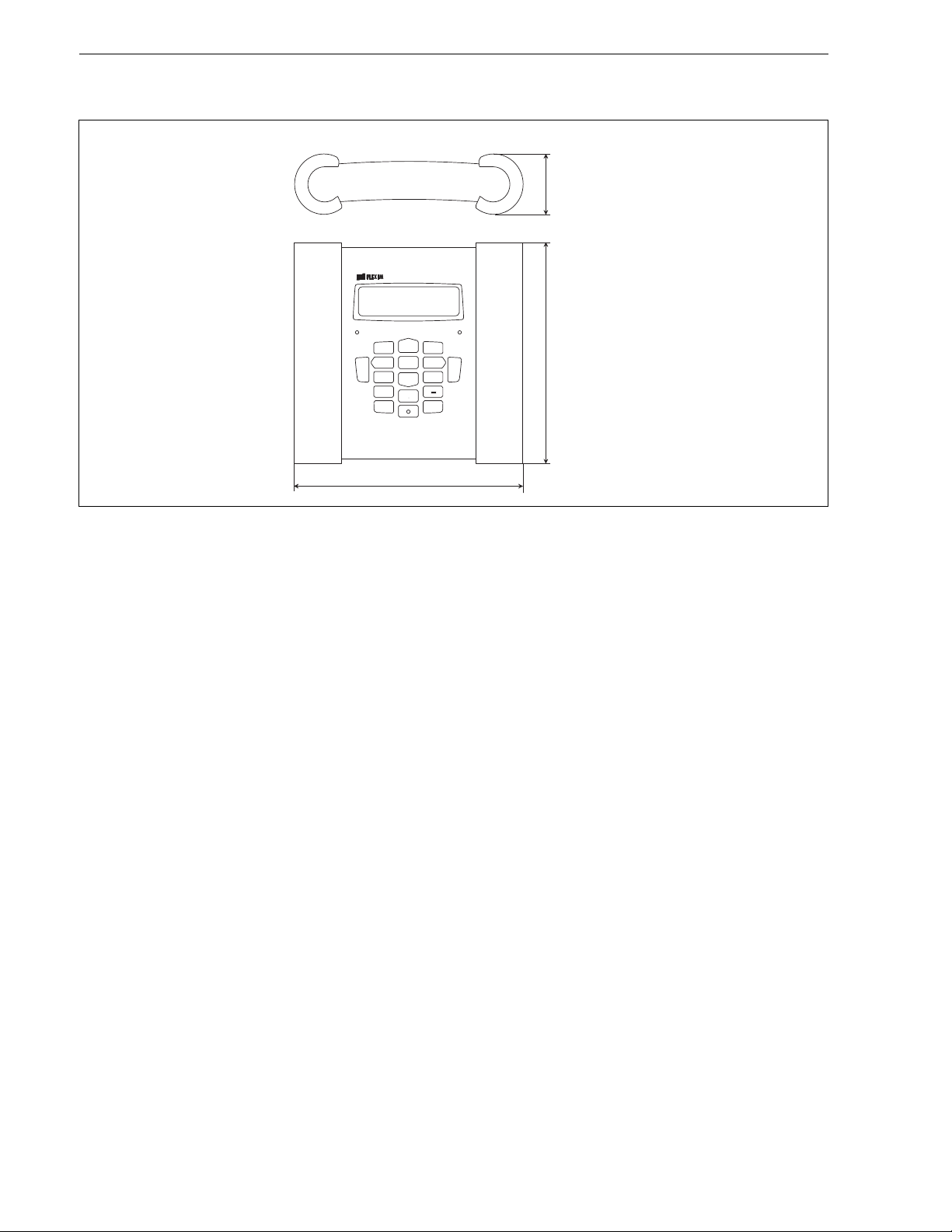
8.9
2.32
8.39
Dimensions
FLUXUS
in inch
8 TSFLUXUS_F601V1-5-1US_Lus, 2014-02-25
Page 9

Technical Specification FLUXUS® F601
C H A C H B
C O M M
P 4 P 3 P 2 P 1
O u t p u t
+
-
D C - I N
C H A C H B
C O M M
P 4 P 3 P 2 P 1
O u t p u t
+
-
In p u t
T 1 /T 3 T 2 / T 4
D C - I N
C H A C H B
C O M M
P 4 P 3 P 2 P 1
O u t p u t
+
-
In p u t
T 1 /T 3 T 2 / T 4
D C - I N
C H A C H B
C O M M
P 2 P 1
O u t p u t
+
-
In p u t
T 1 /T 3 T 2 / T 4
D C - I N
P 3 .. . P 8
Standard Scope of Supply
F601 Standard F601 Energy F601 Double Energy F601 Multifunctional
application flow measurement on liquids
simultaneous monitoring of
flow and energy flow, e.g.
heating systems
outputs
passive current output 2 2 2 4
binary output 2 2 2 2
inputs
temperature input - 2 4 2
passive current input - - - 2
accessories
transport case x x x x
power supply unit,
xxxx
mains cable
batteryxxxx
output adapter - - - x
input adapter - - 2 2
adapter for voltage and
---2
current inputs
QuickFix pipe
xxxx
mounting fixture for
transmitter
serial data kit x x x x
measuring tape x x x x
user manual,
xxxx
Quick Start Guide
connector board at the
upper side of the
transmitter
2 independent measuring channels
temperature-compensated calculation of mass flow rate
integrated heat flow computer for monitoring of energy flows
including energy calculator for BTU and heat measurements
simultaneous monitoring of
2 energy flows, e.g.
heating systems, heat
exchangers)
flow measurement taking
into account other process
quantities, e.g. density,
viscosity
TSFLUXUS_F601V1-5-1US_Lus, 2014-02-25 9
Page 10
FLUXUS® F601 Technical Specification
C H A C H B
C O M M
P 2 P 1
O u t p u t
+
-
In p u t
T 1 /T 3 T 2 /T 4
D C - I N
P 3 . .. P 8
P 3 P 4 P 5 P 6 P 7 P 8
+
-
O u t p u t
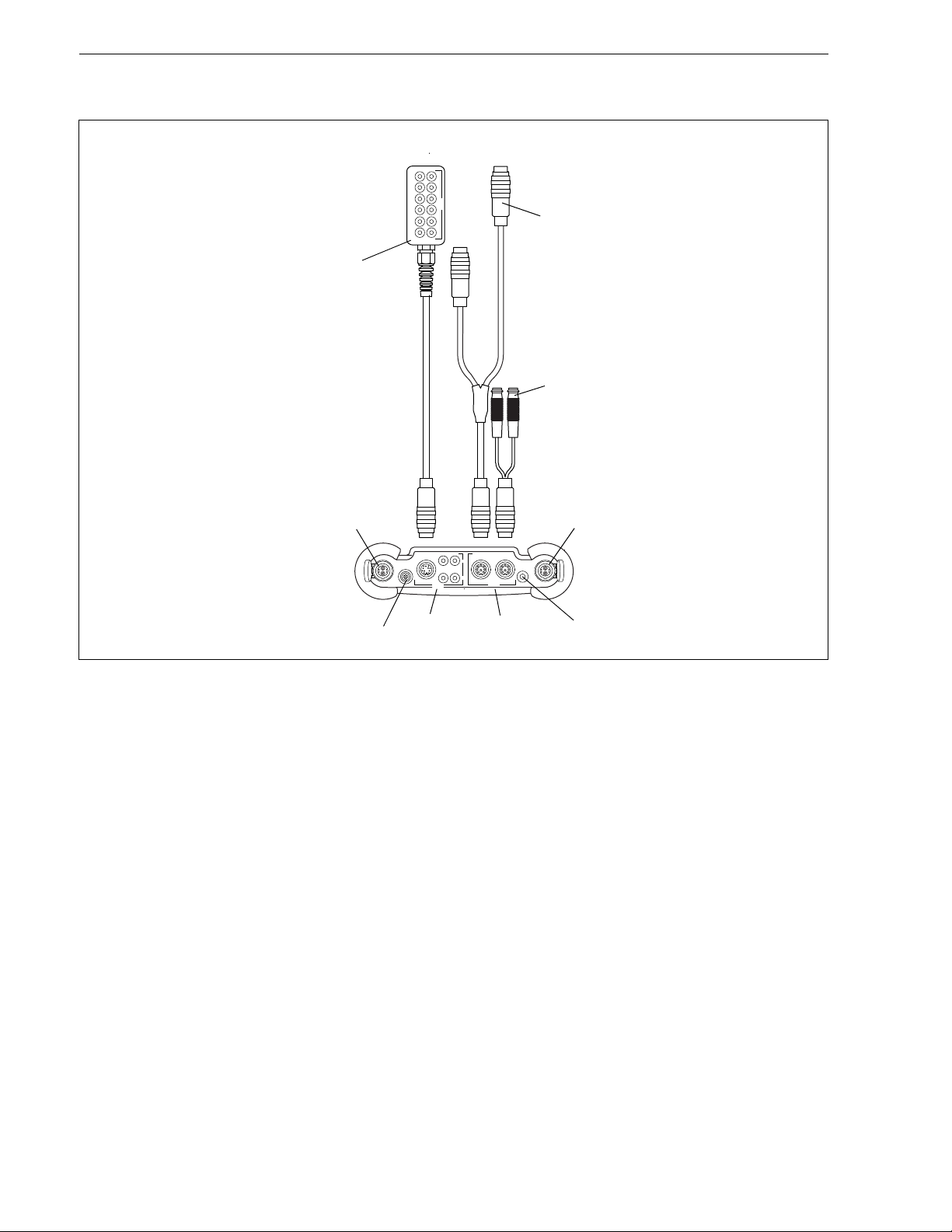
output adapter
input adapter
adapter for voltage and current inputs
transducers
measuring channel A
RS232
outputs inputs
transducers
measuring channel B
power supply unit/battery charging unit
Connection of Adapters
10 TSFLUXUS_F601V1-5-1US_Lus, 2014-02-25
Page 11
Technical Specification FLUXUS® F601
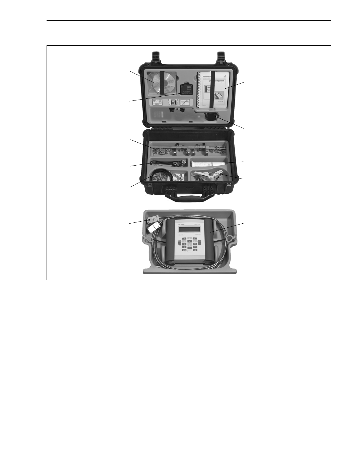
serial data kit
power supply unit, mains cable
transducer mounting fixture
measuring tape
transmitter
transducers
user manual,
Quick Start Guide
coupling compound
wall thickness probe (optional)
QuickFix pipe mounting fixture
temperature probes (optional)
Example for the Equipment of a Transport Case
TSFLUXUS_F601V1-5-1US_Lus, 2014-02-25 11
Page 12

FLUXUS® F601 Technical Specification
Transducers
Transducer Selection
transducer order code
FSK 3.9
FSM 2
FSQ 0.39
FSS 0.24
0.2 0.4 2 4 20 40 200
recommended possible
0.98 5.9 15.7
0.39 2.8
7.9 141.7 255.9
3.9
78.7
133.9
inner pipe diameter [in]
12 TSFLUXUS_F601V1-5-1US_Lus, 2014-02-25
Page 13
Technical Specification FLUXUS® F601
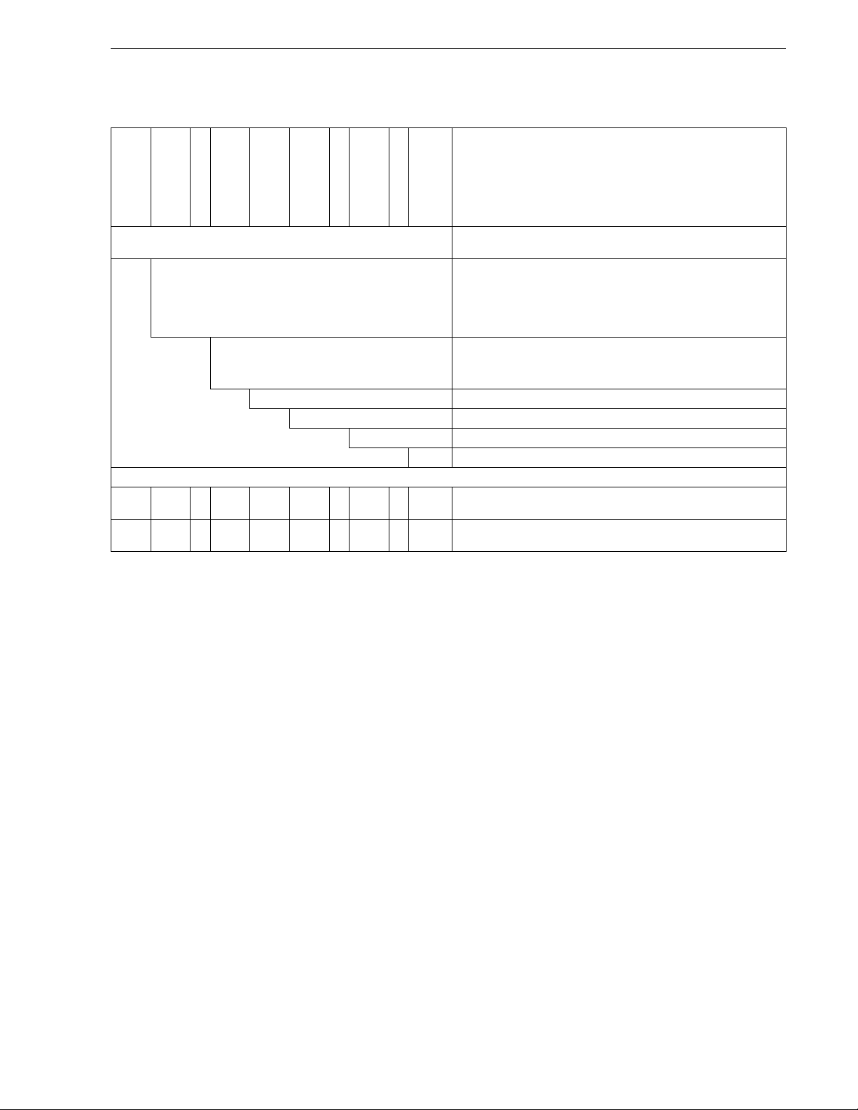
Transducer Order Code
1, 2 3 4 5, 6 7, 8 9 to 11 12, 13 no. of character
description
transducer
transducer
frequency-ambient
FS set of ultrasonic flow transducers for liquids measurement, shear
K 0.5 MHz
M1 MHz
Q4 MHz
S8 MHz
example
FS M - N NN NL - 000 shear wave transducer 1 MHz, normal temperature range,
temperature
explosion
protection
connection
system-extension cable/option
wave
N normal temperature range
E extended temperature range (shear wave transducers with trans-
NN not explosion proof
NL with Lemo connector
XXX cable length in m, for max. length of extension cable see page 22
LC long transducer cable (only FSK)
--/
ducer frequency M, Q)
connection system NL with Lemo connector
TSFLUXUS_F601V1-5-1US_Lus, 2014-02-25 13
Page 14

FLUXUS® F601 Technical Specification
l
h
b
l
h
b
Technical Data
Shear Wave Transducers
technical type CDK1NZ7 CLK1NZ7
order code FSK-NNNNL FSK-NNNNL/LC
transducer frequency MHz 0.5 0.5
inner pipe diameter d
min. extended in 3.9 3.9
min. recommended in 7.9 7.9
max. recommended in 141.7 141.7
max. extended in 255.9 255.9
pipe wall thickness
min. in - max. in - -
material
housing PEEK with stainless steel
cap 304
contact surface PEEK PEEK
degree of protection NEMA 6 NEMA 6
transducer cable
type 1699 1699
length ft 16 29
dimensions
length l in 4.98 4.98
width b in 2.01 2.01
height h in 2.66 2.66
dimensional drawing
PEEK with stainless steel
cap 304
ambient temperature
min. °F -40 -40
max. °F +266 +266
temperature
xx
compensation
14 TSFLUXUS_F601V1-5-1US_Lus, 2014-02-25
Page 15
Technical Specification FLUXUS® F601
h
b
l
h
b
l
h
b
l
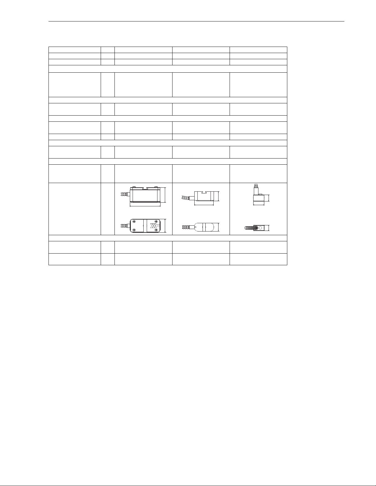
Shear Wave Transducers
technical type CDM1NZ7 CDQ1NZ7 CDS1NZ7
order code FSM-NNNNL FSQ-NNNNL FSS-NNNNL
transducer frequency MHz 1 4 8
inner pipe diameter d
min. extended in 2 0.39 0.24
min. recommended in 3.9 0.98 0.39
max. recommended in 78.7 5.9 2.8
max. extended in 133.9 15.7 2.8
pipe wall thickness
min.in--max.in---
material
housing stainless steel 304 stainless steel 304 stainless steel 304
contact surface PEEK PEEK PEI
degree of protection NEMA 6 NEMA 6 NEMA 4
transducer cable
type 1699 1699 1699
length ft 13 9 6
dimensions
length l in 2.36 1.67 0.98
width b in 1.18 0.71 0.51
height h in 1.32 0.85 0.67
dimensional drawing
ambient temperature
min. °F -40 -40 -22
max. °F +266 +266 +266
temperature
xxx
compensation
TSFLUXUS_F601V1-5-1US_Lus, 2014-02-25 15
Page 16

FLUXUS® F601 Technical Specification
h
b
l
h
b
l
Shear Wave Transducers (extended temperature range)
technical type CDM1EZ7 CDQ1EZ7
order code FSM-ENNNL FSQ-ENNNL
transducer frequency MHz 1 4
inner pipe diameter d
min. extended in 2 0.39
min. recommended in 3.9 0.98
max. recommended in 78.7 5.9
max. extended in 133.9 15.7
pipe wall thickness
min. in - max. in - -
material
housing stainless steel 304 stainless steel 304
contact surface Sintimid Sintimid
degree of protection NEMA 4 NEMA 4
transducer cable
type 1699 1699
length ft 13 9
dimensions
length l in 2.36 1.67
width b in 1.18 0.71
height h in 1.32 0.85
dimensional drawing
ambient temperature
min. °F -22 -22
max. °F +392 +392
temperature
xx
compensation
16 TSFLUXUS_F601V1-5-1US_Lus, 2014-02-25
Page 17

Technical Specification FLUXUS® F601
Transducer Mounting Fixture
Order Code
1, 2 3 4 5 6 7 to 9 no. of character
description
transducer
mounting fixture
transducer-measurement
FS mounting frames
LM ladder chain mounting accessory
VP portable Variofix
TB tension belts
WL transducer box for WaveInjector
A all transducers
K transducers with transducer frequency K
M transducers with transducer frequency M
Q transducers with transducer frequency Q
S transducers with transducer frequency S
example
VP A - D M - C 055 portable Variofix and chains
arrangement
D reflect arrangement or diagonal arrangement/direct mode
R reflect arrangement
Ssmall
M medium
--
-
size
fixation
outer pipe
diameter
C chains
N without fixation
L08 0.5 to 8 in
L22 0.5 to 22 in
010 0.39 to 3.9 in
025 0.39 to 9.8 in
055 0.39 to 21.7 in
150 2 to 59.1 in
210 2 to 82.7 in
TSFLUXUS_F601V1-5-1US_Lus, 2014-02-25 17
Page 18

FLUXUS® F601 Technical Specification
mounting frames FS and chains
transducer frequency: M, Q
material: stainless steel 304,
301, 303
dimensions:
M: 16.54 x 1.89 x 2.68 in
Q: 16.54 x 1.69 x 2.28 in
chain length: 1/3/6 ft
outer pipe diameter:
max. 5.9/12.2/23.6 in
mounting frames FS and magnet (optional)
transducer frequency: S
material: stainless steel 304,
301, 303
dimensions:
8.27 x 1.26 x 1.73 in
chain length: 1 ft
outer pipe diameter:
max. 5.9 in
material: stainless steel 304,
301, 303
dimensions:
M: 16.54 x 1.89 x 2.68 in
Q: 16.54 x 1.69 x 2.28 in
18 TSFLUXUS_F601V1-5-1US_Lus, 2014-02-25
Page 19

Technical Specification FLUXUS® F601
ladder chain mounting accessory LM
transducer frequency: M, Q
chain length: 30/78 in
outer pipe diameter:
max. 24 in
portable Variofix VP and chains
portable Variofix VP and magnet (optional)
material: stainless steel 304,
301, 303
dimensions:
16.3 x 3.7 x 2.99 in
chain length: 6 ft
material: stainless steel 304,
301, 303
dimensions:
16.3 x 3.7 x 1.57 in
TSFLUXUS_F601V1-5-1US_Lus, 2014-02-25 19
Page 20

FLUXUS® F601 Technical Specification
transducer box and
adapter
tension belts TB
transducer frequency: K
material: steel, powder coated
and textile tension belt
length: 16/22 ft
ambient temperature:
max. 140 °F
outer pipe diameter:
max. 59.1/82.7 in
transducer box WL for WaveInjector
see Technical Specification
TSWaveInjectorVx-x
20 TSFLUXUS_F601V1-5-1US_Lus, 2014-02-25
Page 21

Technical Specification FLUXUS® F601
Coupling Materials for Transducers
normal temperature range
(4th character of transducer order
< 212 °F < 338 °F < 302 °F < 392 °F < 536 °F 536 to 752 °F
coupling compound
type N
code = N)
coupling compound
type E
extended temperature range
(4th character of transducer order
coupling compound
type E
code = E)
coupling compound
type E or H
WaveInjector WI-400
coupling foil type A
and coupling foil
type VT
coupling foil type B
and coupling foil
type VT
Technical Data
type order code ambient temperature material remark
°F
coupling compound
type N
coupling compound
type E
coupling compound
type H
coupling foil type A 990739-7 max. 536 lead
coupling foil type B 990739-8 > 536 to 752 silver
coupling foil type VT 990739-0 14 to +392 fluoroelastomer for transducers with transducer
coupling foil not to be used for transducer mounting fixture with magnets
990739-1 -22 to +266 mineral grease paste
990739-2 -22 to +392 silicone paste
990739-3 -22 to +482 fluoropolymer paste
frequency G, H, K
990739-6 for shear wave transducers with
transducer frequency M, P
990739-14 for shear wave transducers IP68
and Lambwave transducers with
transducer frequency M, P
990739-5 for transducers with transducer
frequency Q
TSFLUXUS_F601V1-5-1US_Lus, 2014-02-25 21
Page 22

FLUXUS® F601 Technical Specification
transmitter
l
x
y
-
Connection Systems
connection system NL
transducer frequency
(3d character of transducer
N
L
1
> 82 to 328 ft on request
x, y = transducer cable length
l = max. length of extension cable
cable length (option LC) ft 6 22 ≤ 82---------
order code)
cable length ft 6 9 ≤ 82 6 6 ≤ 82 6 3 ≤ 82 3 3 ≤ 65
G, H, K M, P Q S
1
xyl
xyl1xyl1xyl
Transducer Cable
Technical Data
transducer cable extension cable
type 1699 2551 1750
standard length ft see table above 16
max. length ft - see table above 32
ambient temperature °F -67 to +392 -13 to +176 < 144
sheath
material stainless steel 304 - outer diameter in 0.31 - -
cable jacket
material PTFE TPE-O PE
outer diameter in 0.11 0.31 0.24
thickness in 0.01 0.02
color brown black black
shield x x x
32
22 TSFLUXUS_F601V1-5-1US_Lus, 2014-02-25
Page 23

Technical Specification FLUXUS® F601
h
l
extension cable
h
l
A
B
red/blue red white/blue white
8
1
2
3
4
5
6
7
Clamp-on Temperature Probe (optional)
Technical Data
technical type PT13N PT13N PT13F PT13F
order code 670413-1 670412-1 670413-2 670412-2
design short response time
type Pt1000 2x Pt1000 matched
according to EN 1434-1
connection 4-wire 4-wire
measuring range °F -22 to +482 -58 to +482
accuracy T
±(0.27 °F + 2 . 10-3 . (|T [°F]| - 32 °F)), class A ±(0.27 °F + 2 . 10-3 . (|T [°F]| - 32 °F)), class A
accuracy ∆T-≤ 0.1 K
(3 K < ∆T < 6 K), more
corresponding to
EN 1434-1
response time s 50 8
housing aluminum PEEK, stainless steel 304, copper
degree of protection NEMA 4 NEMA 4
weight (without con-
lb 0.6 1.1 0.7 1.4
nector)
fixation clamp-on clamp-on
accessories
thermal conductivity
xx
paste 392 °F
thermal conductivity
xx
foil 482 °F
plastic protection plate,
-x
insulation foam
dimensions
length l in 0.59 0.55
width b in 0.59 1.18
height h in 0.79 1.06
dimensional drawing A B
Pt1000 2x Pt1000 matched
according to EN 1434-1
- ≤ 0.1 K
(3 K < ∆T < 6 K), more
corresponding to
EN 1434-1
Connection
Temperature Probe
Connector
pin cable of temperature probe extension cable
1 white/blue blue
2red/blue gray
3, 4, 5 not connected
6red red
7white white
8 not connected
Cable
type 4 x 0.25 mm² black or white LIYCY 8 x 0.14 mm² gray
standard length ft 9 16/32/82
max. length ft - 656
cable jacket PTFE PVC
TSFLUXUS_F601V1-5-1US_Lus, 2014-02-25 23
cable of temperature probe extension cable
Page 24

FLUXUS® F601 Technical Specification
DWR1NZ7
Wall Thickness Measurement (optional)
The pipe wall thickness is an important pipe parameter which has to be determined exactly for a good measurement. However, the pipe wall thickness often is unknown.
The wall thickness probe can be connected to the transmitter instead of the flow transducers and the wall
thickness measurement mode is activated automatically.
Acoustic coupling compound is applied to the wall thickness probe which then is placed firmly on the pipe.
The wall thickness is displayed and can be stored directly in the transmitter.
Technical Data
technical type DWR1NZ7
1
measuring range
resolution in 0.0004
accuracy 1 % ± 0.004 in
medium temperature
сable
type 2616
length ft 4
1
The measuring range depends on the attenuation of the ultrasonic signal in the
pipe. For strongly attenuating plastics (e.g. PFA, PTFE, PP) the measuring range is smaller.
in 0.04 to 9.8
-4 to +392,
°F
short-time peak max. 932
Cable
type 2616
ambient temperature °F <392
cable jacket
material FEP
outer diameter in 0.2
color black
shield x
24 TSFLUXUS_F601V1-5-1US_Lus, 2014-02-25
Page 25

FLUXUS® F601 Technical Specification
FLEXIM AMERICAS Corporation
Edgewood, NY 11717
USA
Tel.: (631) 492-2300
Fax: (631) 492-2117
Subject to change without notification. Errors excepted.
®
FLUXUS
is a registered trademark of FLEXIM GmbH.
internet: www.flexim.com
e-mail: usinfo@flexim.com
1-888-852-7473
26 TSFLUXUS_F601V1-5-1US_Lus, 2014-02-25
 Loading...