

Page 1
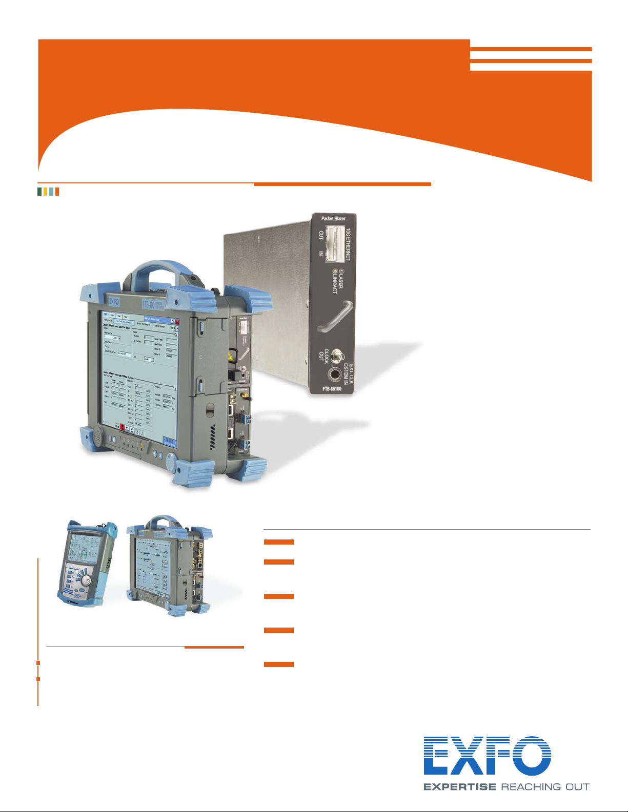
FTB-8510G Packet Blazer
NETWORK TESTING – TRANSPORT AND DATACOM
10 GIGABIT ETHERNET TEST MODULE
Telecom Test and Measurement
www.EXFO.com
FTB-400 Universal Test System
FTB-200 Compact Platform
Platform Compatibility
Performance assurance
for Ethernet-based frame services
LAN and WAN PHY capability in a single module
Fully integrated functionality for assessing the performance
of Ethernet transport networks
Packet jitter measurement to qualify Ethernet transport networks for
transmission of delay-sensitive traffic such as voice-over-IP (VoIP)
Throughput, burstability (back-to-back), latency and frame loss
measurements as per RFC 2544
EtherBERT™ test functionality for assessing the integrity of
10 Gigabit Ethernet running on WDM networks
Page 2
The Choice for 10 Gigabit Ethernet
Performance Assurance
EXFO’s FTB-8510G Packet Blazer™ offers performance assurance for Ethernet-based frame services.
Its suite of test applications provides all the measurements required for validating service-level agreements
(SLAs) between service providers and their customers. Housed in the FTB-400 Universal Test System or
FTB-200 Compact Platform, the FTB-8510G module tests connectivity in its native format: 10GBASE-xR
or 10GBASE-xW used for transport of Ethernet-based LAN-to-LAN services. It can also be used to test
Next-Generation SONET/SDH, hybrid multiplexers, dark fiber or xWDM networks running 10 Gigabit
Ethernet interfaces.
Combined with its rack-mounted manufacturing/R&D-environment counterpart, the IQS-8510G Packet
Blazer, the FTB-8510G simplifies and speeds up the deployment of Ethernet services.
FTB-8510G
10 Gigabit Ethernet Test Module
KEY FEATURES
Measures throughput, back-to-back (burstability), latency and frame loss as per RFC 2544
EtherBERT™
* for bit-error-rate testing of 10 Gigabit Ethernet circuits
Performs packet jitter measurement (IP packet-delay variation as per RFC 3393) to qualify Ethernet transport networks for transmission of delay-sensitive traffic
such as voice-over-IP (VoIP)
Q-in-Q capability with the ability to go up to three layers of stacked VLANs
LAN PHY and WAN PHY available in a single module
Simultaneous traffic generation and reception at 100% wire speed for 10GBASE-SR, -E R, -LR, -SW, -EW or -LW full-duplex interfaces at all valid frame sizes
Transmits and analyzes up to 10 streams, perfect for installing, commissioning and maintaining Ethernet networks
UDP, TCP and IP header integrity validation
Dual test set
Expert mode capability for defining test pass/fail thresholds
Easy-to-use smart user interface (SUI) for configurable screens, customization of test suites, as well as real-time and historical performance reporting
Capability to remote control the Packet Blazer test module with the Visual Guardian Lite software or VNC
Fully compliant to IEEE 802.3ae standard
Pluggable XFP base optical module
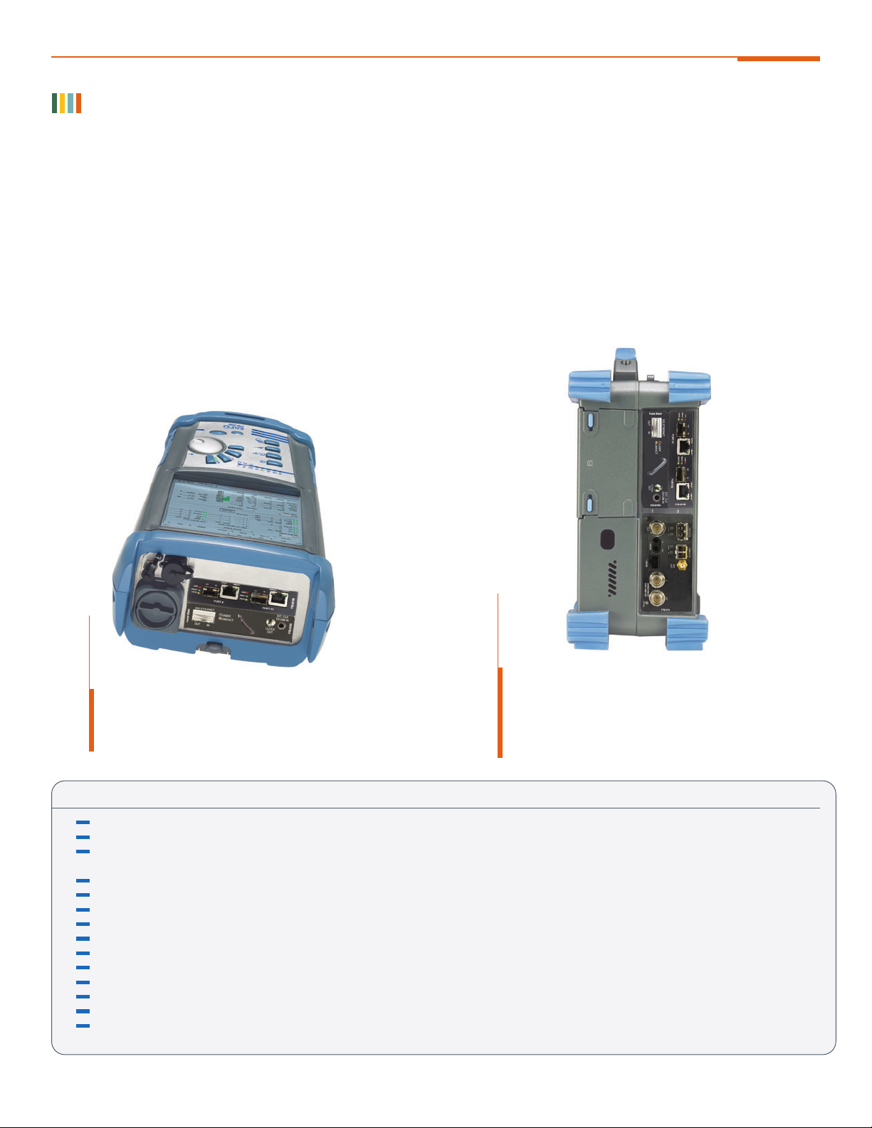
The FTB-8510G Packet Blazer 10 Gigabit Ethernet Test
Module is housed in the FTB-400 Universal Test System,
EXFO’s rugged, all-in-one portable platform. Also shown
in the platform, the FTB-8510B Packet Blazer Ethernet
Test Module and the FTB-8120/8130 Transport Blazer
Next-Gen SONET/SDH Test Module.
The FTB-8510G Packet Blazer 10 Gigabit Ethernet Test
Module can be housed in the FTB-200 Compact Platform.
Also shown in the platform, the FTB-8510B Ethernet
Test Module.
* Patent-pending
Page 3
Ethernet Performance Validation
FTB-8510G
10 Gigabit Ethernet Test Module
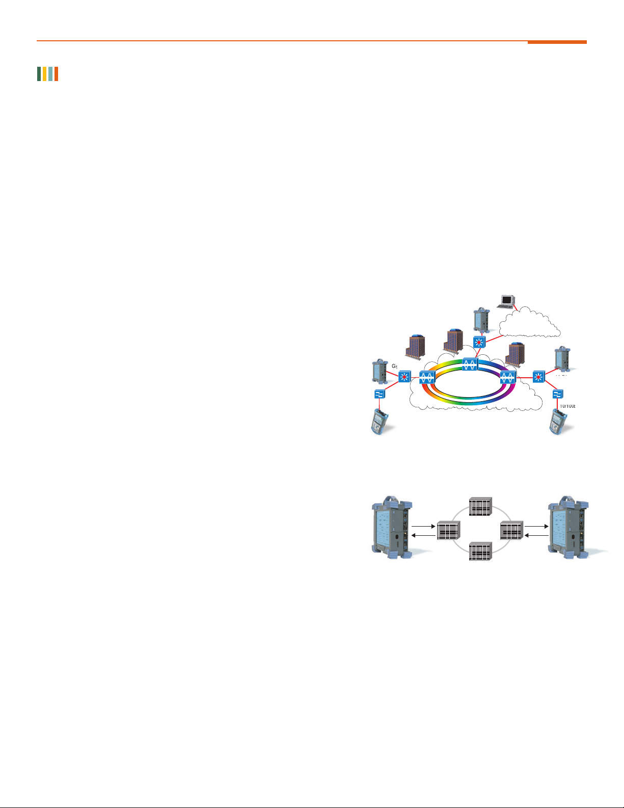
Testing can be performed end-to-end or end-to-core, depending
on the SLA. Remote testing is also possible.
Rx
Local Remote
Metro network
Tx
Tx
Rx
Example of throughput test application.
The Internet Engineering Task Force (IETF) has put together a test methodology to address the issues of performance verification at the
layer 2 and 3 level. RFC 2544, a “Benchmarking Methodology for Network Interconnect Devices,” specifies the requirements and
procedures for testing throughput (performance availability), back-to-back frames (link burstability), frame loss (service integrity) and
latency (transmission delay).
When these measurements are performed, they provide a baseline for service providers to define SLAs with their customers. They enable
service providers to validate the quality of service (QoS) delivered and can provide them with a tool to create value-added services that
can be measured and demonstrated to customers. For example, these tests provide performance statistics and commissioning
verification for virtual LANs (VLANs), virtual private networks (VPNs) and transparent LAN services (TLS), all of which use Ethernet as
an access technology.
The SLA criteria defined in RFC 2544 can be precisely measured using specialized test instruments. The performance verification
is usually done when the installation is completed. The measurements are done out-of-service to make sure that all parameters
are controlled.
RFC 2544 TEST SUITE
The following sections describe each of the RFC 2544 tests. The test
equipment used should be able to generate and analyze traffic for
10GBASE-xR or 10GBASE-xW full duplex networks at all frame sizes in
order to test transparent connectivity for LAN-to-LAN services delivered via
Next-Generation SONET/SDH, SONET/SDH hybrid multiplexers, switched
Ethernet, VLANs, dark fiber, WDM or other means. The instruments should
be capable of transmitting at full line rate, in order to allow the provider to
certify that the circuit is efficient and error-free at 100% utilization.
Some test instruments allow automated testing, which helps to ensure
repeatable results. Automation also provides ease of use for technicians in the
field by enabling accurate, efficient measurements and providing reports they
can give to customers for future reference related to their specific SLAs.
THROUGHPUT
Throughput is the maximum rate at which none of the offered frames are
dropped by the device under test (DUT) or network under test (NUT).
For example, the throughput test can be used to measure the rate-limiting
capability of a switch. The throughput is essentially equivalent to the
bandwidth.
The throughput test allows vendors to report a single value which has
proven to be useful in the marketplace. Since even the loss of one frame in
a data stream can cause significant delays while waiting for the higher level
protocols to time out, it is useful to know the actual maximum data rate that
the device can support. Measurements should be taken over an assortment
of frame sizes. Separate measurements should be made for routed and
bridged data in those devices that can support both. If there is a checksum
in the received frame, full checksum processing should be done.
Throughput test procedure:
1. Send a specific number of frames at a specific rate through the DUT/NUT
and then count the frames that are transmitted by the DUT/NUT.
2. If the count of offered frames is equal to the count of received frames, the rate
of the offered stream is raised and the test rerun.
3. If fewer frames are received than were transmitted, the rate of the offered stream
is reduced and the test is rerun.
4. The throughput is the fastest rate at which the count of test frames transmitted
by the DUT/NUT is equal to the number of test frames sent to it by the test equipment.
Gigabit Ethernet
10/100Base-T
10 GigE
Metro Network
Internet
10 GigE
Gigabit Ethernet
10/100Base-T
Page 4

Ethernet Performance Validation (Cont'd)
BURST (BACK-TO-BACK)
In this test, fixed-length frames are presented at a rate such that there
is the minimum legal separation for a given medium between frames
over a configurable period of time, starting from an idle state.
The back-to-back value is the number of frames in the longest burst
that the DUT/NUT will handle without the loss of any frames.
FTB-8510G
10 Gigabit Ethernet Test Module
LATENCY
For store and forward devices, latency is the time interval starting when the last bit of the input frame reaches the input port and ending when
the first bit of the output frame is seen on the output port. Roundtrip latency is the time it takes a frame to come back to its starting point.
Variability of latency can be a problem. With technologies like VoIP, a variable or long latency can cause degradation in voice quality.
FRAME LOSS
Frame loss is the percentage of frames that should have been forwarded by a
network device under steady state (constant) loads that were not forwarded due
to lack of resources. This measurement can be used in reporting the
performance of a network device in an overloaded state. This can be a useful
indication of how a device would perform under pathological network conditions
such as broadcast storms.
Metro
Network
Metro
Network
X
Number of bytes
Number of bytes
Burst
Burst
Example of burst (back-to-back) test application.
Burst test procedure:
1. Send a burst of frames with minimum inter-frame gaps to the DUT/NUT
and count the number of frames forwarded by the DUT/NUT.
2. If the count of transmitted frames is equal to the number of frames forwarded, the length of the burst is increased and the test is rerun.
3. If the number of forwarded frames is less than the number transmitted, the length of the burst is reduced and the test is rerun.
4. The back-to-back value is the number of frames in the longest burst that the DUT/NUT will handle without the loss of any frames.
5. The trial length must be at least 2 seconds and should be repeated at least 50 times with the average of the recorded values being reported.
Frame loss test procedure:
1. Send a specific number of frames at a specific rate through the DUT/NUT to be tested
and count the frames that are transmitted by the DUT/NUT.
2. The frame loss at a particular line rate is calculated using the following equation:
% Frame loss = Transmitted frames – Received frames X 100
Transmitted frames
3. Measurement should be done for different frame sizes.
Metro
Network
Example of latency test application.
Start time:
Return time:
Latency test procedure:
1. Determine the throughput of the DUT/NUT for each frame size.
2. Send a stream of frames at a particular frame size through the DUT/NUT at
the determined throughput rate to a specific destination.
3. Send a tagged frame after 60 seconds and store timestamp (A). Capture tag
frame on reception side and store timestamp (B).
4. The latency is timestamp B minus timestamp A.
5. The test must be repeated at least 20 times with the reported value being the
average of the recorded values.
86% frames lost
at 10 Gbit/s
Metro
Network
Example of frame loss test application.
Metro
Network
Example of frame loss test application.
74% frames lost
at 9 Gbit/s
Page 5

FTB-8510G
10 Gigabit Ethernet Test Module
BERT OVER ETHERNET
Because transparent transport of Ethernet over physical media is becoming a
common service, Ethernet is increasingly carried across a variety of layer 1 media
over longer distances. There is therefore a growing need to certify Ethernet transport
on a bit-per-bit basis. This can be done using bit-error-rate testing (BERT).
BERT uses a pseudo-random binary sequence (PRBS) encapsulated into an
Ethernet frame, making it possible to go from a frame-based error measurement
to a bit-error-rate measurement. This provides the bit-per-bit error count accuracy
required for the acceptance testing of physical-medium transport systems.
BERT over Ethernet should be used when Ethernet is carried transparently over
layer 1 media, in cases such as:
Ethernet-over-DWDM
Ethernet-over-CWDM
Ethernet-over-dark fiber
FRAME ANALYSIS
This FTB-8510G Packet Blazer feature enables multistream traffic generation
and analysis allowing for the troubleshooting of Ethernet circuits as well as
customer-traffic analysis and error identification. Thanks to its packet jitter
measurement capability (RFC 3393), the FTB-8510G lets service providers
efficiently benchmark transport networks when it comes to delay-sensitive traffic
such as voice-over-IP (VoIP).
SMART LOOPBACK
This feature allows transmitting back the received stream of data.
To perform an end-to-end frame analysis, BERT or RFC 2544
across a layer 2, traffic needs to be looped back to the originator.
A remote unit running the Smart Loopback mode will allow traffic
to be returned to the local unit by swapping packet overhead up
to layer 4.
ETHERNET SERVICE ACCEPTANCE TESTING
The type of testing required for Ethernet service acceptance
testing depends on how the service is carried on the network.
The opposite figure shows how to test for switched transport
or transparent physical transport using either RFC 2544 tests or
BERT-over-Ethernet.
All of the tests that are part of the service-level agreement can be
performed on either part of the network (end-to-core) or on all of it
(end-to-end). For both switched transport and transparent physical
transport, end-to-end testing can be performed by using two
portable units and testing from one end to the other. Another way
of doing this is to send a technician to one site and test using
a second test device that is mounted in the network (e.g., in a
central office). This type of testing is useful when two technicians
cannot be sent at the same time or when the service provider is
providing access to the Internet.
Service accepted
Switch transport Transparent physical transport
RFC 2544
Packet jitter
BERT
Are SLA performance
parameters met?
Is media 100% error free?
Ye s N o
No
Ye s
Service rejected
Is the Ethernet service delivered via switched
transport or via transparent physical transport?
TX
RX
Metro Network
Example of EtherBERT Configuration.
Metro
Network
Example of Smart Loopback test application.
Page 6

Functional Specifications
FTB-8510G
10 Gigabit Ethernet Test Module
10BASE-SW 10BASE-SR 10BASE-LW 10BASE-LR 10BASE-EW 10BASE-ER
Wavelength 850 nm 850 nm 1310 nm 1310 nm 1550 nm 1550 nm
Multimode Multimode Singlemode Singlemode Singlemode Singlemode
Tx level (802.3ae-compliant) –7.3 to –1 dBm –7.3 to –1 dBm –8.2 to +0.5 dBm –8.2 to +0.5 dBm –4.7 to +4.0 dBm –4.7 to +4.0 dBm
Rx level sensitivity –9.9 to –1.0 dBm –9.9 to –1.0 dBm –14.4 to +0.5 dBm –14.4 to +0.5 dBm –15.8 to –1.0 dBm –15.8 to –1.0 dBm
Transmission bit rate
9.95328 Gbit/s ± 4.6 ppm* 10.3125 Gbit/s ± 4.6 ppm* 9.95328 Gbit/s ± 4.6 ppm* 10.3125 Gbit/s ± 4.6 ppm* 9.95328 Gbit/s ± 4.6 ppm* 10.3125 Gbit/s ± 4.6 ppm*
Reception bit rate
9.95328 Gbit/s ± 150 ppm 10.3125 Gbit/s ± 150 ppm 9.95328 Gbit/s ± 150 ppm 10.3125 Gbit/s ± 150 ppm 9.95328 Gbit/s ± 150 ppm 10.3125 Gbit/s ± 150 ppm
Tx operational wavelength range 840 nm to 860 nm 84 0 nm to 860 nm 1260 nm to 1355 nm 1260 nm to 1355 nm 1530 nm to 1565 nm 1530 nm to 1565 nm
(802.3ae-compliant)
Measurement accuracy
Frequency ±4.6 ppm ±4.6 ppm ±4.6 ppm ±4.6 ppm ±4.6 ppm ±4.6 ppm
Optical power < 2 dB < 2 dB < 2 dB < 2 dB < 2 dB < 2 dB
Maximum Rx before damage
0 dBm 0 dBm +1.5 dBm +1.5 dBm +4.0 dBm +4.0 dBm
Jitter compliance IEEE 802.3ae IEE E 802.3ae IEEE 802.3ae IEE E 802.3ae IEEE 802.3ae IEE E 802.3ae
Ethernet classification IEEE 802.3ae IEEE 802.3ae IEEE 802.3ae IEEE 802.3ae IEEE 802.3ae IEEE 802.3ae
Laser type VCSEL VCSEL DFB DFB EML EML
Eye safety Class 1 laser; complies Class 1 laser; complies Class 1 laser; complies Class 1 laser; complies Class 1M laser; complies Class 1M laser; complies
with 21 CFR 1040.10 with 21 CFR 1040.10 with 21 CFR 1040.10 with 21 CFR 1040.10 with 21 CFR 1040.10 with 21 CFR 1040.10
and IEC 60825-1 and IEC 60825-1 and IEC 60825-1 and IEC 60825-1 and I EC 60825-1 and IEC 60825-1
Connector Duplex LC Duplex LC Duplex LC Duplex LC Duplex LC Duplex LC
Transceiver type XFP XFP XFP XFP XFP XFP
(compliant with XFP MSA)
* When clocking is in internal mode
SYNCHRONIZATION INTERFACES
DS1/E1 external input clock interface
Parameter DS1 E1
Rx level sensitivity (short haul only) For 772 kHz: For 1024 kHz:
TERM: 6 dB (cable loss only) TERM: 6 dB (cable loss only)
Reception bit rate 1.544 Mbit/s ± 50 ppm 2.048 Mbit/s ± 50 ppm
Input jitter tolerance AT&T PUB 62411, GR-499 section 7.3 G.823 section 7.2
Line coding AMI and B8ZS HDB3 and AMI
Input impedance 100 ohms ± 5%, balanced 120 ohms ± 5%, balanced
(resistive termination)
Connector type BANTAM BANTAM
OPTICAL INTERFACES
Clock out interface
Parameter Value
Tx pulse amplitude 600 mVpp ± 130 mV
Transmission frequency LAN WAN
Clock divider = 16 644.53 MHz 622.08 MHz
Clock divider = 32 322.266 MHz 311.04 MHz
Clock divider = 64 161.133 MHz 155.52 MHz
Output configuration AC coupled
Load impedance 50 ohms
Maximum cable length 3 meters
Connector type SMA
Page 7

FTB-8510G
10 Gigabit Ethernet Test Module
Functional Specifications (Cont’d)
OPTICAL INTERFACES
Optical interfaces 10 GigE LAN and 10 GigE WAN
Available wavelengths 850, 1310 and 1550 nm
ELECTRICAL INTERFACES
Electrical interfaces Ext. clock DS1/E1 and clock output
Ext. clock DS1/E1 Line coding DS1: AMI and B8ZS
E1: AMI and HDB3
Termination mode DS1/E1: Term
Framing DS1: SF and ESF
E1: PCM30, PCM30CRC, PCM31 and PCM31CRC
Clocking Internal, external (BITS) and recovered
Clock output Clock out Clock out divider: 16, 32 and 64
TESTING
RFC 2544 Throughput, back-to-back, frame loss and latency measurements according to RFC 2544. Frame size: RFC-defined sizes, user-configurable.
BERT Unframed layer 1 up to layer 4 with or without VLAN Q-in-Q
Patterns (BERT) PRBS 2E9-1, PRBS 2E11-1, PRBS 2E15-1, PRBS 2E20-1, PRBS 2E23-1, PRBS 2E31-1, and up to ten user patterns
Error insertion (BERT) FCS, bit, 64B/66B Block
Error measurement LAN/WAN: jabber/giant, runt, undersize, oversize, FCS, 64B/66B Block
WAN: B1, B2, B3, REI-L, RE I-P
UDP, TCP and IP header checksum
Error measurement (BERT) Bit error, bit mismatch 0, bit mismatch 1, performance monitoring (G.821 and G.826)
Alarm insertion LOS, link down, local fault, remote fault, LSS (BERT)
WAN: SEF, LOF, AIS-L, RDI-L, AIS-P, RDI-P, LCD-P, LOP-P, ERDI-PSD, E RDI-PCD, ERDI-PPD, UNEQ-P
Alarm detection LOS, link down, local fault, remote fault, frequency offset, LSS (BERT)
WAN: SEF, LOF, AIS-L, RDI-L, AIS-P, RDI-P, LCD-P, LOP-P, ERDI-PSD, E RDI-PCD, ERDI-PPD, PLM-P, UNEQ-P, Link (WIS)
Service disruption time measurement (BERT) Defect or No Traffic mode. Disruption time statistics include shortest, longest, last, average, total and count.
Multistream generation Capability to transmit up to 10 streams. Configuration parameters are: packet size, transmission mode (Burst, Ramp or Continuous),
MAC source/destination address, VLAN ID, VLAN priority, IP source/destination address, ToS field, DSCP field and
UDP source/destination port.
VLAN stacking Capability to generate streams with up to three layers of VLAN (including IEEE802.1ad QinQ tagged VLAN) and to filter received traffic by VLAN ID or
VLAN priority at any of the stacked VLAN layers.
Traffic analysis Capability to analyze the incoming traffic and provide statistics according to a set of up to 10 configurable filters. Filters can be configured
for MAC source/destination address, VLAN ID, VLAN priority, IP source/destination address, ToS field, DSCP field, TCP source/destination port and UDP
source/destination port. VLAN filtering can be applied to any of the stacked VLAN layers.
Ethernet statistics Multicast, broadcast, unicast, N-unicast, pause frame, frame size distribution, bandwidth, utilization, frame rate, frame loss,
out-of-sequence frames, in-sequence frames.
Jitter statistics Generation: packet jitter simulation: VoIP G.711, VoIP G.723.1, G.729, user-defined
Analysis: delay variation statistics (ms): min., max., last, average, number of samples, jitter measurement estimate
Flow control injection Packet pause time
(frame analyzer)
Flow control statistics Pause time, last pause time, max. pause time, min. pause time, paused frames, abort frames, frames Tx, frames Rx
(frame analyzer and RFC 2544)
ADDITIONAL TEST AND MESUREMENT FUNCTIONS
Power measurement Supports optical power measurement, displayed in dBm.
Frequency generation and measurement Supports clock frequency generation and measurements (i.e., received frequency and deviation of the input signal clock from nominal frequency).
Frequency offset generation:
Range: ±120 ppm
Resolution: ±1 ppm
Accuracy: ±4.6 ppm
Frequency offset measurement:
Range: ±150 ppm
Resolution: ±1 ppm
Accuracy: ±4.6 ppm
Signal label control and monitoring Ability to configure and monitor J0 Trace, J1 Trace and payload signal label C2 (WAN).
Dual test set Performs end-to-end, bidirectional performance testing (as required by leading standards bodies)—remote Packet Blazer
controlled via the LAN connection under test.
DHCP client Capability to connect to a DHCP server to obtain its I P address and subnet mask to connect to the network.
Smart Loopback Capability to return traffic to the local unit by swapping packet overhead up to layer 4 of the OSI stack.
ADDITIONAL FEATURES
Expert mode Ability to set thresholds in RFC 2544 and BERT mode to provide a PASS/FAIL status.
Scripting The built-in Visual Basic .NET scripting engine and embedded macrorecorder provide a simple means of automating test cases and routines.
Embedded scripting routines provide a powerful means of creating advanced test scripts.
a
Event logger Supports logging of test results, and the ability to print, export (to a file), or export the information contained in the logging tool.
Power up and restore
a
In the event of a power failure to the unit, the active test configuration and results are saved and restored upon bootup.
Save and load configuration Ability to store and load test configurations to/from non-volatile memory.
Configurable test views Allows users to customize their test views, i.e., to dynamically insert or remove test tabs/windows, in addition to creating new
test windows, so as to accurately match their testing needs.
a
Configurable test timer Allows a user to set a specific start and stop time for tests.
Test favorites Capability to select and load from predefined or user-modified test conditions.
Report generation Ability to generate test reports in the following user-selectable formats: .pdf, .html, .txt and .csv.
Graph Allows to graphically display the test statistics of the performance (RFC 2544) and frame analysis tests.
Screen capturing
b
Capability to gather a snap-shot of the screen for future use.
Logger printing
b
Capability to send logger messages to a supported local printer.
Remote control Remote control through Visual Guardian Lite software or VNC.
NOTES
a. Available on the FTB-400 Universal Test System platform only. b. Available on the FTB-200 Compact Platform only.
Page 8

FTB-8510G
10 Gigabit Ethernet Test Module
SPFTB8510G.6AN © 2007 EXFO Electro-Optical Engineering Inc. All rights reserved. Printed in Canada 07/10
EXFO Corporate Headquarters > 400 Godin Avenue, Quebec City (Quebec) G1M 2K2 CANADA Tel.: 1 418 683-0211 Fax: 1 418 683-2170 info@EXFO.com
Toll-free: 1 800 663-3936 (USA and Canada) www.EXFO.com
EXFO is certified ISO 9001 and attests to the quality of these products.
This device complies with Part 15 of the FCC Rules. Operation is
subject to the following two conditions: (1) this device may not cause
harmful interference, and (2) this device must accept any interference
received, including interference that may cause undesired operation.
EXFO has made every effort to ensure that the information contained
in thi s speci ficatio n sheet is accurate. All of EXFO’s manufactured
products are compliant with the European Union’s WEEE directive. For
more information, please visit www.EXFO.com/recycle. However, we
accept no responsibility for any errors or omissions, and we reserve the
right to modify design, characteristics and products at any time witho ut
obligation. Units of measurement in this document conform to SI
standards and practices. Contact EXFO for prices and availability or to
obtain the phone number of your local EXFO distributor.
For the most recent version of this spec sheet, please go to the EXFO
website at http://www.EXFO.com/specs
In case of discrepancy, the Web version takes precedence over a ny print ed
literature.
EXFO America 3701 Plano Parkway, Suite 160 Plano, TX 75075 USA Tel.: 1 800 663-3936 Fax: 1 972 836-0164
EXFO Europe Omega Enterprise Park, Electron Way Chandlers Ford, Hampshire S053 4SE ENGLAND Tel.: +44 2380 246810 Fax: +44 2380 246801
EXFO Asia 151 Chin Swee Road, #03-29 Manhattan House SINGAPORE 169876 Tel.: +65 6333 8241 Fax: +65 6333 8242
EXFO China No. 88 Fuhua, First Road Shenzhen 518048, CHINA Tel.: +86 (755) 8203 2300 Fax: +86 (755) 8203 2306
Central Tower, Room 801, Futian District
Beijing New Century Hotel Office Tower, Room 1754-1755 Beijing 100044 P. R. CHINA Tel.: +86 (10) 6849 2738 Fax: +86 (10) 6849 2662
No. 6 Southern Capital Gym Road
ORDERING INFORMATION
FTB-8510G-XX
MODULE
MODULE SPECIFICATIONS
FTB-8510G-LAN FTB-8510G-WAN FTB-8510G-LAN/WAN
Port One 10 Gigabit Ethernet port One 10 Gigabit Ethernet port One 10 Gigabit Ethernet port
Connector type LC LC LC
Optical transceiver 850 nm optics (10GBASE-SR) 850 nm optics (10GBASE-SW) 850 nm optics (10GBASE-SR/-SW)
1310 nm optics (10GBASE-LR) 1310 nm optics (10GBASE-LW) 1310 nm optics (10GBASE-LR/-LW)
1550 nm optics (10GBASE-ER) 1550 nm optics (10GBASE-EW) 1550 nm optics (10GBASE-ER/-EW)
Port capacity Full-line-rate traffic generation and analysis Full-line-rate traffic generation and analysis Full-line-rate traffic generation and analysis
Ethernet testing RFC 1242, RFC 2544, RFC 3393, multistream RFC 1242, RFC 2544, RFC 3393, multistream RFC 1242, RFC 2544, RFC 3393, multistream
traffic generation and analysis, EtherBERT traffic generation and analysis, EtherBERT traffic generation and analysis, EtherBERT
GENERAL SPECIFICATIONS
Size (H x W x D) 25 mm x 96 mm x 260 mm (1 in x 3 in x 10 in)
Weight (without transceiver) 0.5 kg (1.2 lb)
Temperature operating 0 °C to 40 °C (32 °F to 104 °F)
storage —40 °C to 60 °C (—40 °F to 140 °F)
Model
FTB-8510G-LAN = Packet Blazer 10 GigE, 1 port 10 Gigabit Ethernet
LAN PHY (10.3125 Gbit/s)
FTB-8510G
-WAN = Packet Blazer 10 GigE, 1 port 10 Gigabit Ethernet WAN PHY
(9.953 Gbit/s)
FTB-8510G
-LAN/WAN = Packet Blazer 10 GigE, 1 port 10 Gigabit Ethernet
LAN and WAN PHY (10.3125 and 9.953 Gbit/s)
Example: FTB-8510G-LAN
OPTION
FTB-8585 = Software option converting an FTB-8510G-LAN or
FTB-8510G-WAN to a FTB-8510G-LAN/WAN model.
NET-SDK = .NET automation software development kit and
programmer’s guide
ACCESSORIES
FTB-85900 = 10GBase-SR/-SW (850 nm, LAN/WAN PHY) LC connectors;
optical XFP transceiver module for 8510G Packet Blazer
FTB-85901 = 10GBase-LR/-LW (1310 nm, LAN/WAN PHY) LC connectors;
optical XFP transceiver module for 8510G Packet Blazer
FTB-85902 = 10GBase-E R/-EW (1550 nm, LAN/WAN PHY) LC connectors;
optical XFP transceiver module for 8510G Packet Blazer
Specifications are subject to change without notice.
 Loading...