

Page 1
Best tool for characterizing PMD in
the field
Highest dynamic range on the market—more than 50 dB
Greatest analysis range:
0.05 to 200 ps (typical)
Second-order PMD calculation
Part of the rugged and portable
FTB-300 Universal Test System
PMD Analyzer
MODULE
FTB-5500
Fiber-optic test and measurement equipement
Page 2
PMD Affects System Performance
Dispersion phenomenon
Polarization mode dispersion (PMD) affects system performance by spreading the pulse over the length of a fiber.Pulse spreading can be compared
to power loss in the system, because it directly affects the loss safety margin.
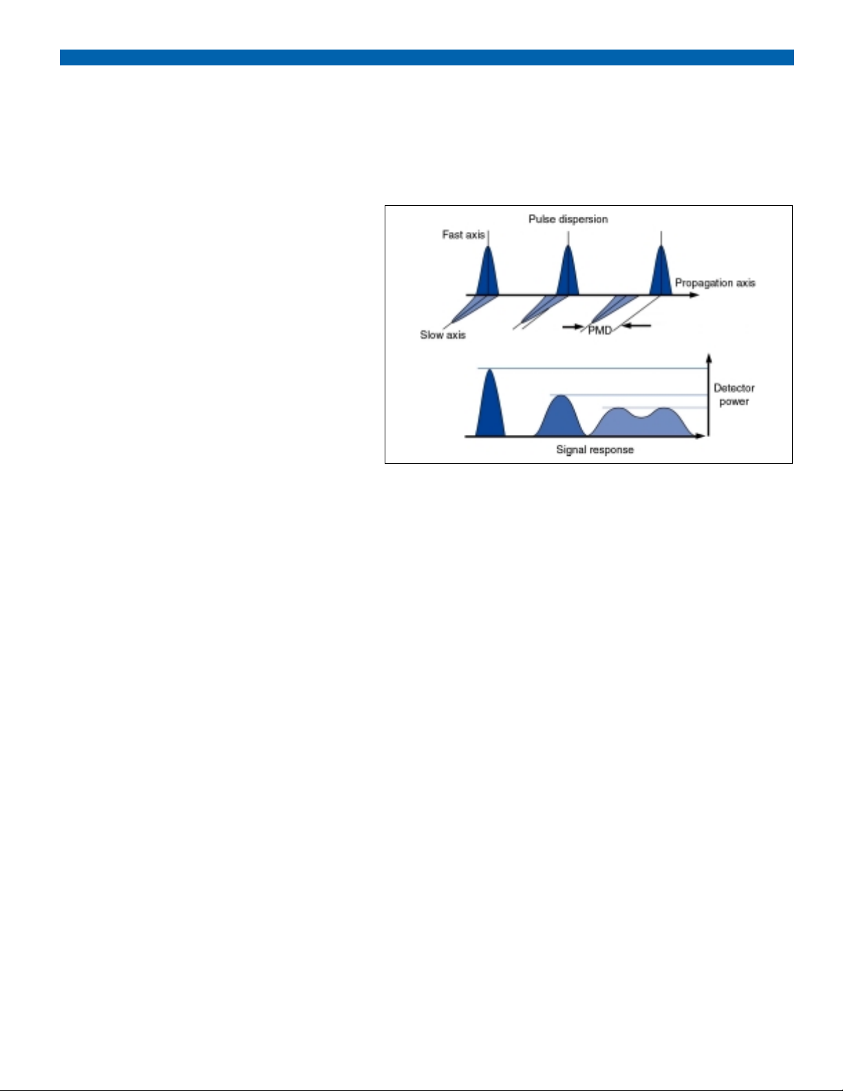
PMD is caused by asymmetry in the fiber’s geometry and/or by
localized stress throughout the waveguide. Birefringence in the
optical fiber, which causes light to be propagated along two polarization axes that are orthogonal to each other, produces slow
and fast axes.The difference in propagation speed results in temporal spreading or dispersion as shown in the figure to the right.
With a digital signal, PMD increases the BER, which, limits system bandwidth.With an analog signal, PMD creates distortion,
limiting the number of channels.
Network planners quickly realized the danger of this situation: an entire
bandwidth upgrade could be jeopardized by PMD. Consequently, plenty
of testing was carried out when the industry recognized the importance
of characterizing PMD in existing networks.
The introduction of the interferometric method subsequently changed
the reality of PMD measurement.The interferometric method, which was
introduced by the GAP Optique team from the University of Geneva,
quickly demonstrated its usefulness as a fast and secure way of measuring PMD, regardless of environmental conditions.
The interferometric method allows field measurement of PMD; this is not
possible with conventional methods such as JME or wavelength scanning.The interferometric method is faster and almost immune to vibrations and adverse field conditions.
With the marketing of OC-192 (STM-64) and the advent of OC-768
(STM-256), fiber and cable manufacturers eventually acknowledged the
importance of PMD and began guaranteeing specifications.
In light of these developments, however, companies who specialize in
cable installation, maintenance, and troubleshooting still need to be concerned about PMD for a number of reasons:
• PMD is statistical in nature.
• Large variation in PMD values can be observed during the life
cycle of a fiber.
• Additional stress can be applied to a fiber during transportation
and cabling.
• Effects of temperature and vibration are still regarded as
potential problems by operators.
• Cable can be crushed, stressed, or physically damaged
during installation.
• Cable handling causes variations in PMD.
The TIA standard
The inteferometric method is the fastest PMD measurement method.It
was approved by the TIA in April 1999 (EIA/TIA-455-124). The test
method documentation demonstrates the validity of the method and its
limitation in accuracy for PMD values smaller than 0.12 ps using a standard LED source at 1550 nm.With this method, no end-to-end communication is required.This allows for less equipment and human intervention as well as faster, more efficient data collection.
A major concern for network planners
Page 3

Measuring PMD the Smart Way
The FTB-5500 PMD Analyzer module uses a Michelson interferometer
to accurately measure PMD delay. It performs a mean measurement
over the entire wavelength range of a broad-spectrum polarized LED
source. After fitting the Gaussian distribution curve, the analysis software calculates and displays the fiber’s total PMD and second-order
PMD value and coefficient.
Vibration-proof: The broad spectrum and shor t coherence time of the
LED source used in the interferometric method renders the EXFO
PMD analyzer almost immune to vibration.This characteristic is especially important when testing installed cables. Acquisition speed is also a
factor with regard to vibration immunity.
Fast results: The interferometric method also provides fast results by
automating the measurement process.The software typically completes
the test cycle in 15 seconds.
High dynamic range
Averaging PMD over the entire source wavelength range (without filtering) preserves full power for PMD measurement.The standard
40 dB dynamic range remains available for testing long fiber spans.
A high dynamic range option, using EXFO’s M-2100 Broadband Light
Source, a high-power EELED source, increases the dynamic range to
more than 50 dB to measure fiber spans longer than 250 km.
Great measurement range
The interferometric method can handle high PMD values.An extended
range option increases the instrument's analysis from 0.05 to 200 ps.
The measurement range of the instrument goes from 0.1 to 115 ps, but
users can obtain calculated values down to 0.05 ps and estimated values from 115 up to 200 ps.
Second-order PMD
Second-order PMD is derived from the measured PMD value and is proportional to the link length, unlike first-order PMD.This means that second-order PMD is particularly impor tant in long-distance links. Moreover,
second-order PMD, because it is based on the mean variation in the
slope of the first-order PMD curve, is wavelength-dependent.
EXFO's PMD software provides second-order PMD delay and coefficient
values.These figures help to characterize fibers and cables more precisely than simple PMD, which makes for better control of transmission
quality in both digital and analog high-bandwidth systems.
Field-proof advanced technology
Page 4

PMD at the Touch of a Button
Simple step-by-step measurements
Step-by-step instructions make testing easy and virtually error-free.
Due to the user-friendly software, novices and experts can obtain
fast, accurate, and efficient PMD measurements with little training.
Automated testing mode
The unique auto-range function scans all the measurement ranges
and automatically provides the PMD range best suited for measurement.This option is extremely useful when testing a fiber in
which the expected PMD value is unknown.
To reduce the auto-range measurement time, it is also possible to
select a maximum Auto Highest Range.This reduces scanning
time by eliminating the higher range.
Auto-diagnostic capabilities
In default mode, the software performs an auto-diagnosis on measured PMD and supplies the user with comments and suggestions.
Multiple-measurement possibilities
This software also features a multiple-measurement mode that
allows users to average several PMD measurements taken over a
long period of time.
Statistical result tables
After completing multiple tests, the PMD analyzer automatically
compiles the results in a table and provides statistical results:
• mean PMD delay and coefficient
• standard deviation PMD delay and coefficient
• minimum and maximum PMD delay and coefficient
Several data management features
The software also includes a variety of data management features
such as file auto-naming and statistical and table management.
The PMD Analyzer quickly produces the results you need.
The PMD Analyzer provides a threshold alarm with maximum recommended PMD values.
Auto-diagnosis makes it easier to obtain accurate measurements.
Page 5

Get Ready for the Future
EXFO, a world leader in fiber-optic test equipment, has been
working on PMD for many years.In fact, we were the first
fiber-optic test and measurement company to introduce a PMD
test instrument for the field.
The FTB-5500 PMD Analyzer module provides the user with
instant access to all test modes in a true multitasking environment, thus increasing testing efficiency.This user-friendly software
makes it easy to learn and work; ease-of-use reduces training
costs. Combined with the Windows 95-based operating system,
the PMD software offers an enhanced graphical user interface that
definitely takes the guesswork out of testing.
Now more than ever, it is essential to test fiber-optic cables during
manufacturing and after installation to ensure that a network can
handle higher bit rates.When turning up bandwidth, PMD is a definite concern. The FTB-5500 PMD Analyzer helps you evaluate
the potential to upgrade your network.
The FTB-300 Universal Test System, which hosts the FTB-5500
PMD Analyzer, is a future-proof test platform featuring test modules than can be purchased or upgraded as needed. Here is a
selection of the modules that perform advanced testing and monitoring tasks:
• FTB-7000 OTDR Series (including the 1625 nm OTDR)
• FTB-5240 Optical Spectrum Analyzer
• FTB-5320 Multi-Wavelength Meter
• FTB-9000 Optical Switch
EXFO's exclusive ToolBox 5 software suite runs the test module
applications on the FTB-300 Universal Test System.The software's easy-to-read graphics and clear instructions simplify testing
and increase productivity in the field. In addition, all applications
have a common structure and graphical user interface (GUI)—
once you've grasped one ToolBox application, learning another is
smooth and simple. And to keep you in sync with the latest technology, we release frequent updates, upgrades, and new applications.
The platform advantage
Leading the way
Page 6

SPECIFICATIONS (FTB-5500 PMD ANALYZER)
Model FTB-5502 FTB-5503 FTB-5523
Wavelength (nm) 1310 1550 1310/1550
Analysis range
1
(ps)
standard (typ.) 0.06 to 35 0.05 to 35 0.05
2
to 35
extended range (typ.) 0.06 to 200 0.05 to 200 0.05
2
to 200
(ER option)
Dynamic range3(dB) 45 (50)
4
40 (48)
4
32 (40)
4
Average measuring time (s) 15 15 15
GENERAL SPECIFICATIONS (FTB-5500 PMD ANALYZER)
Temperature operating 5 to 40°C 41 to 104°F
storage −20 to 60°C −4 to 140°F
Relative humidity 0 to 80% non-condensing
NOTES
1. Measurement range is 0.1 to 115 ps with a calculated value lower than 0.1 ps
and estimated value higher than 115 ps.
2. With the 1550 nm light source.
3. At 1 ps.
4. With the M-2100 Broadband Light Source.
STANDARD ACCESSORIES
Instruction manual, PMD software, connector cleaners
SPFTBPMDAnalyzer.4AN 00/09
© 2000 EXFO Electro-Optical Engineering Inc. All rights reserved.
Printed in Canada
CORPORATE HEADQUARTERS 465 Godin Avenue, Vanier QC G1M 3G7 Canada Tel.:(418) 683-0211 Fax: (418) 683-2170
EXFO AMERICA 1201 Richardson Drive, Suite 260, Richardson, TX, 75080, USA Tel.:1 800 663-3936 Fax: (972) 907-2297
EXFO EUROPE Centre d’Affaires Les Metz, 100, rue Albert Calmette, 78353, Jouy-en-Josas, France Tel.:+33 1 34 63 00 20 Fax: +33 1 34 65 90 93
EXFO ASIA Honkomagome 6-6-20 Bunkyo-Ku T-113 0021 Tokyo-To Japan Tel.: +81-3-5940-5410 Fax: +81-3-5940-5415
1 800 663-3936
info@exfo.com
www.exfo.com
ORDERING INFORMATION
FTB-300 Universal Test System PMD Analyzer module Polarized light source Broadband light source
FTB-300-XX FTB-55XX-XX-XX FLS-110-XXP-XX M21XX-BP-XX-XXX
Option code 02 = 1310 nm 02 = 1310 nm LED 02 =1300 nm
D2 = Active color matrix touchscreen 03 = 1550 nm 03 = 1550 nm LED 03 =1545 nm
M1 = 3.5 in. floppy disk 23 = 1310/1550 nm P = polarized
W1 = PCMCIA interface ER = extended range option Connector type BP = Polarized EELED
W2 = PCMCIA interface and 14.4 kBds fax/modem card 89 = FC/UPC singlemode fiber source
N3 = 4 MB memory upgrade (total of 20 MB) Connector type 90 = ST/UPC
89 = FC/UPC Connector code
N4 = 16 MB memory upgrade (total of 32 MB) 90 = ST/UPC 58 = FC/APC
Power code
115 V
220 V
SPECIFICATIONS (FTB-300 UTS)
Display touchscreen, monochrome, 640x480 full dot LCD 9.4 in.
touchscreen, active matrix color, 640x480 full dot
LCD 8.4 in. (optional)
Interfaces RS-232
parallel printer
external VGA monitor
external keyboard (PS/2)
PCMCIA type II (optional, for fax modem card)
Memory 16 MB RAM, internal 2.1 GB hard drive
internal 3.5 in. 1.44 MB floppy drive (optional)
Batteries rechargeable NiMH battery pack (two batteries)
Four hours of continuous operation as per Bellcore
TR-NWT-001138
Power supply AC input: 90 to 250 V, 50/60 Hz
Size (H x W x D) 22.9cm x 30.5cm x 10.1 cm 9 in. x 12 in. x 4 in.
Weight 6.52 kg 14.35 lb.
F
O
X
E
Y
T
I
L
A
U
Q
1
0
1
0
0
9
0
9
O
S
O
I
S
C
I
D
E
R
E
I
T
F
I
 Loading...