

Page 1
Manufacturers > Rohde & Schwarz
Categories > Spectrum | Signal Analyzers > Low Frequency, FFT Spectrum
\ Signal Analyzers > Spectrum \ Signal Analyzers greater than 26.5 GHz >
EMC Test Equipment > Conducted \ Radiated Emissions Test > EMI Analyz-
ers \ EMC Receivers
How-To Video
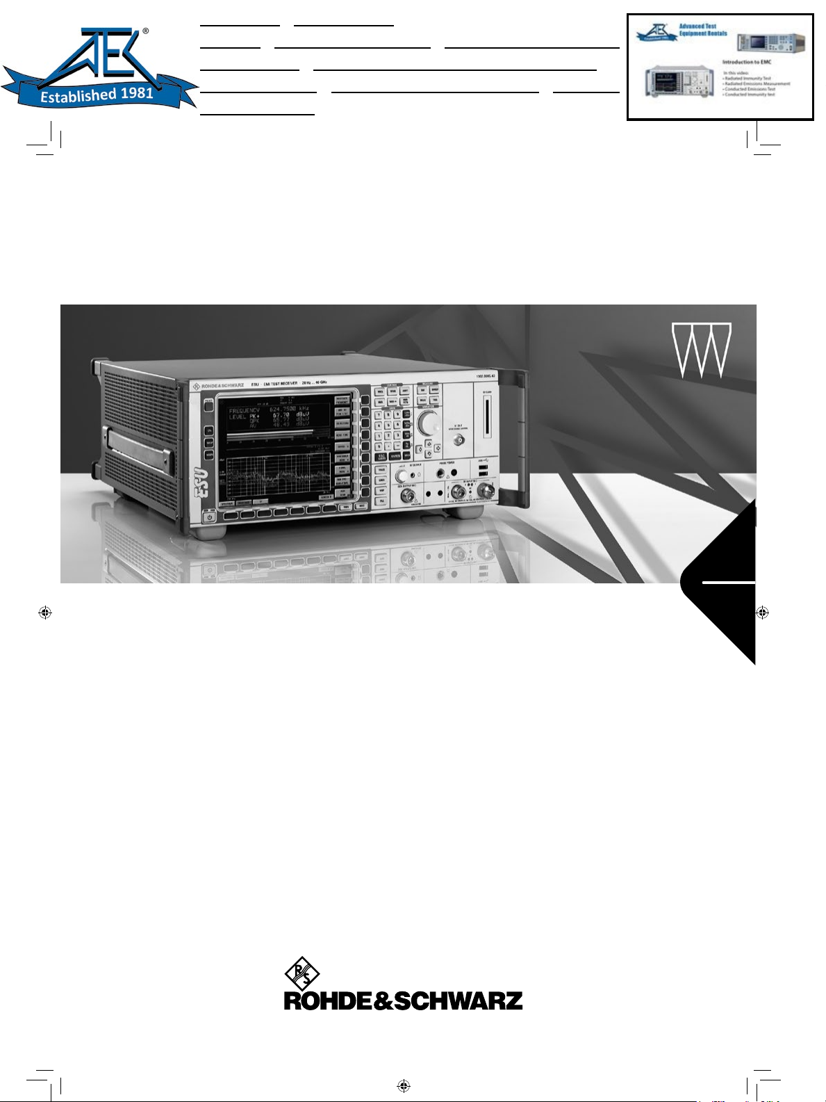
¸ESU EMI Test Receiver
Data sheet
Version
02.00
October
2007
TitelundRueck.indd 1 19.10.2007 14:19:52
Page 2

CONTENTS
BASE UNIT ................................................................................................................................................................................................3
FREQUENCY .............................................................................................................................................................................................3
RECEIVER SCAN........................................................................................................................................................................................4
SWEEP .....................................................................................................................................................................................................4
PRESELECTION .........................................................................................................................................................................................4
IF AND RESOLUTION BANDWIDTHS..............................................................................................................................................................5
LEVEL.......................................................................................................................................................................................................5
I/Q DATA.................................................................................................................................................................................................11
AUDIO DEMODULATION ............................................................................................................................................................................11
TRIGGER FUNCTIONS ..............................................................................................................................................................................12
INPUTS AND OUTPUTS (FRONT PANEL)......................................................................................................................................................12
INPUTS AND OUTPUTS (REAR PANEL)........................................................................................................................................................13
GENERAL SPECIFICATIONS ......................................................................................................................................................................14
R&S®FSU-B9 TRACKING GENERATOR, R&S®FSU-B12 ATTENUATOR FOR TRACKING GENERATOR.......................................15
R&S®ESU-B24 LOW-NOISE PREAMPLIFIER........................................................................................................................................17
ORDERING INFORMATION ....................................................................................................................................................................22
OPTIONS ................................................................................................................................................................................................22
RECOMMENDED EXTRAS..........................................................................................................................................................................23
Specifications apply under the following conditions: 30 minutes warm-up time at ambient temperature, specified environmenttal conditions met, calibration cycle adhered to, and total calibration performed. Data without tolerances: typical values
only. Data designated 'nominal' applies to design parameters and is not tested.
2 R&S®ESU EMI Test Receiver Version 02.00, October 2007
Page 3
Base Unit
Frequency
Frequency range
Frequency resolution 0.01 Hz
R&S®ESU8
DC coupled 20 Hz to 8 GHz
AC coupled 1 MHz to 8 GHz
R&S®ESU26
DC coupled 20 Hz to 26.5 GHz
AC coupled 10 MHz to 26.5 GHz
R&S®ESU40
DC coupled 20 Hz to 40 GHz
AC coupled 10 MHz to 40 GHz
all models
DC coupled, input 2 20 Hz to 1 GHz
AC coupled, input 2 9 kHz to 1 GHz
Reference frequency, internal, nominal standard OCXO
Aging per day after 30 days of continuous operation 1 × 10
Aging per year after 30 days of continuous operation 1 × 10
–9
–7
Temperature drift +5° C to +45° C 8 × 10⁻⁸
Total error per year 1.8 × 10⁻⁷
Reference frequency, internal, nominal option R&S®FSU-B4
Aging per day after 30 days of continuous operation 2 × 10
Aging per year after 30 days of continuous operation 3 × 10
–10
–8
Temperature drift +5° C to +45° C 1 × 10⁻⁹
Total error per year 5 × 10⁻⁸
External reference frequency 1 MHz to 20 MHz, 1 Hz steps
Frequency display
Marker resolution
with marker or frequency counter
span/624
Maximum deviation sweep time >3 × auto sweep time ±(marker frequency × reference error +
0.5 % × span +10 % × resolution
bandwidth + ½ (last digit))
Frequency counter resolution selectable 0.1 Hz to 10 kHz
Count accuracy S/N >25 dB ±(frequency × reference error +
½ (last digit))
Display range for frequency axis
Resolution
Max. span deviation
0 Hz, 10 Hz to max. frequency
0.1 Hz
1 %
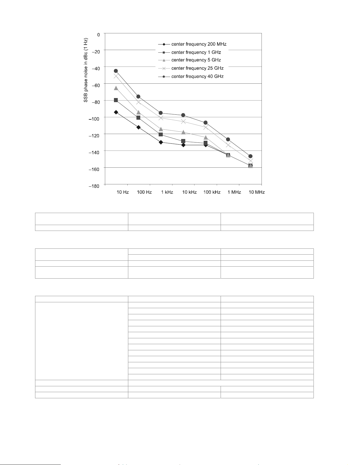
Spectral purity,
SSB phase noise (1 Hz)
f = 640 MHz
Residual FM RBW 10 kHz, RMS <1 Hz nominal
Carrier offset
10 Hz <–73 dBc, nominal
10 Hz with option R&S®FSU-B4 fitted <–86 dBc, nominal
100 Hz <–98 dBc, typ. –104 dBc
1 kHz <–116 dBc, typ. –124 dBc
10 kHz <–128 dBc, typ. –133 dBc
100 kHz <–128 dBc, typ. –133 dBc
1 MHz <–140 dBc, typ. –146 dBc
10 MHz typ. –160 dBc
Version 02.00, October 2007 R&S
®
ESU EMI Test Receiver 3
Page 4
Receiver scan
Scan scan with max. 10 subranges with different
Measurement time per frequency selectable 10 µs to 100 s
settings
Sweep
time sweep, span = 0 Hz 1 µs to 16000 s in steps of 5 % Sweep time
Max. deviation of sweep time 3 %
Measurement in time domain
frequency sweep, span ≥10 Hz 2.5 ms to 16000 s in steps of ≤10 %
with marker and cursor lines
(resolution 31.25 ns)
Preselection
Preselection can be switched off in analyzer mode 13 preselection filters
Bandwidth (–6 dB), nominal
Preamplifier switchable between preselection and 1st mixer
Range 1 kHz to 3.6 GHz
Gain 20 dB, nominal
20 Hz to 150 kHz 230 kHz, fixed lowpass filter
150 kHz to 2 MHz 2.6 MHz, fixed bandpass filter
2 MHz to 8 MHz 2 MHz, tracking bandpass filter
8 MHz to 30 MHz 6 MHz, tracking bandpass filter
30 MHz to 70 MHz 15 MHz, tracking bandpass filter
70 MHz to 150 MHz 30 MHz, tracking bandpass filter
150 MHz to 300 MHz 60 MHz, tracking bandpass filter
300 MHz to 600 MHz 80 MHz, tracking bandpass filter
600 MHz to 1 GHz 100 MHz, tracking bandpass filter
1 GHz to 2 GHz tracking highpass filter
2 GHz to 3 GHz fixed highpass filter
3 GHz to 3.6 GHz fixed highpass filter
3.6 GHz to 8/26.5/40 GHz 60 MHz + f/500, YIG filter
4 R&S®ESU EMI Test Receiver Version 02.00, October 2007
Page 5
IF and resolution bandwidths
3 dB bandwidths 10 Hz to 10 MHz in 1/2/3/5 sequence
Bandwidth uncertainty
Shape factor 60 dB:3 dB
10 Hz to 100 kHz (digital) <3 %
200 kHz to 5 MHz (analog) <10 %
10 MHz –30 % to +10 %
≤100 kHz <6
200 kHz to 2 MHz <12
3 MHz to 10 MHz <7
6 dB bandwidths 10 Hz, 100 Hz, 200 Hz, 1 kHz, 9 kHz,
Bandwidth uncertainty 3 %
Shape factor 60 dB:6 dB <5
FFT filters (analyzer mode only)
3 dB bandwidths 1 Hz to 30 kHz in 1/2/3/5 sequence
Bandwidth uncertainty <5 %, nominal
Shape factor 60 dB:3 dB <3, nominal
Channel filters
Bandwidths
Shape factor 60 dB:3 dB <2, nominal
Bandwidth uncertainty <2 %, nominal
Video bandwidths (analyzer mode only) 1 Hz to 10 MHz in 1/2/3/5 sequence
100, 200, 300, 500 Hz,
with option R&S
®
ESPI-K50: 5.6 MHz (ISDB-T, Japan),
10 kHz, 100 kHz, 120 kHz, 1 MHz
1, 1.5, 2, 2.4, 2.7, 3, 3.4, 4, 4.5, 5, 6, 8.5,
9, 10, 12.5, 14, 15, 16, 18 (RRC), 20, 21,
24.3 (RRC), 25, 30, 50, 100, 150, 192,
200, 300, 500 kHz,
1, 1.2288, 1.28 (RRC), 1.5, 2, 3,
3.84 (RRC), 4.096 (RRC), 5 MHz
6.0 MHz (DVB-T, USA), 6.4 MHz
Level
Display range displayed noise floor to 137 dBµV
Maximum input level
RF input, AC coupled 50 V DC voltage
RF input, DC coupled 0 V
RF attenuation 0 dB 127 dBµV (= 0.1 W) CW RF power
RF attenuation ≥10 dB 137 dBµV (= 1.0 W)
Pulse spectral density 97 dBµV/MHz
Max. pulse voltage
Version 02.00, October 2007 R&S
RF attenuation ≥10 dB
input 1 150 V
input 2 450 V
RF attenuation ≥10 dB, 10 µs, input 1 1 mWs Max. pulse energy
RF attenuation ≥10 dB, 10 µs, input 2 20 mWs
®
ESU EMI Test Receiver 5
Page 6
Intermodulation
1 dB compression of input mixer
Third-order intercept point (TOI)
Second harmonic intercept (SHI)
0 dB RF attenuation, preselection/preamplifier = OFF1
≤3.6 GHz +13 dBm, nominal
>3.6 GHz
R&S®ESU8 +10 dBm, nominal
®
R&S
ESU26/40 +7 dBm, nominal
level 2 × –10 dBm, Δf > 5 × RBW or 10 kHz, whichever is larger
preselection/preamplifier = OFF1
R&S®ESU8
10 MHz ≤ fin < 300 MHz >17 dBm, typ. 20 dBm
300 MHz ≤ fin < 3.6 GHz >20 dBm, typ. 25 dBm
3.6 GHz ≤ fin ≤ 8 GHz >18 dBm, typ. 23 dBm
R&S®ESU26, R&S®ESU40
10 MHz ≤ fin < 300 MHz >17 dBm, typ. 20 dBm
300 MHz ≤ fin < 3.6 GHz >22 dBm, typ. 27 dBm
3.6 GHz ≤ fin ≤ 26.5 GHz >12 dBm, typ. 15 dBm
R&S®ESU40
26.5 GHz < fin ≤ 40 GHz >12 dBm, typ. 15 dBm
preselection = ON, preamplifier = OFF
10 MHz ≤ fin < 300 MHz >9 dBm, typ. 12 dBm
300 MHz ≤ fin ≤ 3.6 GHz >12 dBm, typ. 15 dBm
preselection = ON, preamplifier = ON
10 MHz ≤ f
≤ 3.6 GHz >–10 dBm, typ. –7 dBm
in
preselection/preamplifier = OFF1
f < 100 MHz >35 dBm
100 MHz < fin ≤ 400 MHz >45 dBm, typ. 55 dBm
400 MHz < fin ≤ 500 MHz >52 dBm, typ. 60 dBm
500 MHz < fin ≤ 1 GHz >45 dBm, typ. 55 dBm
1 GHz < fin ≤ 1.8 GHz >35 dBm
fin > 1.8 GHz >80 dBm, nominal
preselection = ON, preamplifier = OFF
fin < 100 MHz >40 dBm
100 MHz < fin ≤ 1.8 GHz >55 dBm, typ. 65 dBm
preselection = ON, preamplifier = ON
fin < 100 MHz >35 dBm
100 MHz < f
≤ 1.8 GHz >45 dBm, typ. 55 dBm
in
Displayed average noise level (analyzer mode)
RF attenuation = 0 dB, termination = 50 Ω, log. scaling, normalized to 1 Hz RBW,
preselection = OFF, preamplifier = OFF
f < 10 kHz: 10 Hz FFT Filter, trace average, sweep count = 20
f ≥ 10 kHz: RBW = 1 kHz, VBW = 3 kHz, span = 0 Hz, sweep time = 50 ms, trace
average, sample detector, sweep count = 20, mean marker
all models
20 Hz <–90 dBm
100 Hz <–110 dBm
1 kHz <–120 dBm
10 kHz <–130 dBm
100 kHz <–130 dBm
1 MHz <–140 dBm
10 MHz <–153 dBm
R&S®ESU8
20 MHz ≤ f < 1 GHz <–154 dBm, typ. –158 dBm
1 GHz ≤ f < 2 GHz <–152 dBm, typ. –155 dBm
2 GHz ≤ f < 3.6 GHz <–148 dBm, typ. –151 dBm
3.6 GHz ≤ f < 7 GHz <–152 dBm, typ. –154 dBm
7 GHz ≤ f ≤ 8 GHz <–150 dBm, typ. –152 dBm
1
Only available in analyzer mode.
6 R&S®ESU EMI Test Receiver Version 02.00, October 2007
Page 7
®
R&S
ESU26
20 MHz ≤ f < 1 GHz <–152 dBm, typ. –156 dBm
1 GHz ≤ f < 2 GHz <–150 dBm, typ. –154 dBm
2 GHz ≤ f < 3.6 GHz <–147 dBm, typ. –150 dBm
3.6 GHz ≤ f < 8 GHz <–152 dBm, typ. –156 dBm
8 GHz ≤ f < 13 GHz <–150 dBm, typ. –153 dBm
13 GHz ≤ f < 18 GHz <–148 dBm, typ. –151 dBm
18 GHz ≤ f < 22 GHz <–147 dBm, typ. –150 dBm
22 GHz ≤ f ≤ 26.5 GHz <–145 dBm, typ. –148 dBm
R&S®ESU40
20 MHz ≤ f < 1 GHz <–152 dBm, typ. –156 dBm
1 GHz ≤ f < 2 GHz <–150 dBm, typ. –154 dBm
2 GHz ≤ f < 3.6 GHz <–147 dBm, typ. –150 dBm
3.6 GHz ≤ f < 8 GHz <–150 dBm, typ. –153 dBm
8 GHz ≤ f < 13 GHz <–148 dBm, typ. –151 dBm
13 GHz ≤ f < 18 GHz <–146 dBm, typ. –149 dBm
18 GHz ≤ f < 22 GHz <–145 dBm, typ. –147 dBm
22 GHz ≤ f < 26.5 GHz <–143 dBm, typ. –145 dBm
26.5 GHz ≤ f < 33 GHz <–141 dBm, typ. –144 dBm
33 GHz ≤ f ≤ 40 GHz <–138 dBm, typ. –141 dBm
RF attenuation = 0 dB, termination = 50 Ω, log. scaling, normalized to 1 Hz RBW,
preselection = ON, preamplifier = OFF
f < 10 kHz: RBW = 10 Hz, VBW = 30 Hz, trace average, sample detector, sweep count
= 20, mean marker
f ≥ 10 kHz: RBW = 1 kHz, VBW = 3 kHz, span = 0 Hz, sweep time = 50 ms, trace
average, sample detector, sweep count = 20, mean marker
all models
20 Hz typ. <–90 dBm
100 Hz <–110 dBm
1 kHz <–120 dBm
10 kHz <–130 dBm
100 kHz <–130 dBm
1 MHz <–140 dBm
10 MHz <–153 dBm
R&S®ESU8
20 MHz ≤ f < 2 GHz <–155 dBm, typ. –158 dBm
2 GHz ≤ f < 2.5 GHz <–153 dBm, typ. –156 dBm
2.5 GHz ≤ f < 3 GHz <–150 dBm, typ. –153 dBm
3 GHz ≤ f ≤ 3.6 GHz <–145 dBm, typ. –148 dBm
R&S®ESU26/40
20 MHz ≤ f < 1 GHz <–155 dBm, typ. –158 dBm
1 GHz ≤ f < 2 GHz <–153 dBm, typ. –156 dBm
2 GHz ≤ f < 2.5 GHz <–151 dBm, typ. –154 dBm
2.5 GHz ≤ f < 3 GHz <–147 dBm, typ. –151 dBm
3 GHz ≤ f ≤ 3.6 GHz <–142 dBm, typ. –146 dBm
RF attenuation = 0 dB, termination = 50 Ω, log. scaling, normalized to 1 Hz RBW,
preselection = ON, preamplifier = ON
f < 10 kHz: RBW = 10 Hz, VBW = 30 Hz, trace average, sample detector, sweep count
= 20, mean marker
f ≥ 10 kHz: RBW = 1 kHz, VBW = 3 kHz, span = 0 Hz, sweep time = 50 ms, trace
average, sample detector, sweep count = 20, mean marker
all models
1 kHz <–130 dBm
10 kHz <–140 dBm
100 kHz <–140 dBm
1 MHz <–150 dBm
10 MHz <–165 dBm
R&S®ESU8
20 MHz ≤ f < 500 MHz <–165 dBm, typ. –168 dBm
500 MHz ≤ f < 2 GHz <–163 dBm, typ. –166 dBm
2 GHz ≤ f < 3 GHz <–161 dBm, typ. –164 dBm
3 GHz ≤ f ≤ 3.6 GHz <–157 dBm, typ. –160 dBm
R&S®ESU26/40
20 MHz ≤ f < 500 MHz <–163 dBm, typ. –166 dBm
500 MHz ≤ f < 2 GHz <–161 dBm, typ. –164 dBm
2 GHz ≤ f < 3 GHz <–160 dBm, typ. –163 dBm
3 GHz ≤ f ≤ 3.6 GHz <–155 dBm, typ. –158 dBm
Version 02.00, October 2007 R&S
®
ESU EMI Test Receiver 7
Page 8
Noise indication (receiver mode)
Nominal, calculated from DANL data
RF attenuation = 0 dB, termination = 50 Ω, average (AV) detector, preamplifier = OFF
all models
20 Hz, BW = 10 Hz <27 dBµV
100 Hz, BW = 10 Hz <7 dBµV
1 kHz, BW = 100 Hz <7 dBµV
10 kHz, BW = 200 Hz <0 dBµV
100 kHz, BW = 200 Hz <0 dBµV
1 MHz, BW = 9 kHz <7 dBµV
10 MHz, BW = 9 kHz <–6 dBµV
R&S®ESU8
20 MHz ≤ f < 30 MHz, BW = 9 kHz <–8 dBµV
30 MHz ≤ f < 1 GHz, BW = 120 kHz <3 dBµV
1 GHz ≤ f < 2 GHz, BW = 1 MHz <12 dBµV
2 GHz ≤ f < 2.5 GHz, BW = 1 MHz <14 dBµV
2.5 GHz ≤ f < 3 GHz, BW = 1 MHz <17 dBµV
3 GHz ≤ f < 3.6 GHz, BW = 1 MHz <22 dBµV
3.6 GHz ≤ f < 7 GHz, BW = 1 MHz <15 dBµV
7 GHz ≤ f ≤ 8 GHz, BW = 1 MHz <17 dBµV
R&S®ESU26
20 MHz ≤ f < 30 MHz, BW = 9 kHz <–8 dBµV
30 MHz ≤ f < 1 GHz, BW = 120 kHz <3 dBµV
1 GHz ≤ f < 2 GHz, BW = 1 MHz <12 dBµV
2 GHz ≤ f < 2.5 GHz, BW = 1 MHz <16 dBµV
2.5 GHz ≤ f < 3 GHz, BW = 1 MHz <20 dBµV
3 GHz ≤ f < 3.6 GHz, BW = 1 MHz <25 dBµV
3.6 GHz ≤ f < 8 GHz, BW = 1 MHz <15 dBµV
8 GHz ≤ f < 13 GHz, BW = 1 MHz <17 dBµV
13 GHz ≤ f < 18 GHz, BW = 1 MHz <19 dBµV
18 GHz ≤ f < 22 GHz, BW = 1 MHz <20 dBµV
22 GHz ≤ f ≤ 26.5 GHz, BW = 1 MHz <22 dBµV
R&S®ESU40
20 MHz ≤ f < 30 MHz, BW = 9 kHz <–8 dBµV
30 MHz ≤ f < 1 GHz, BW = 120 kHz <3 dBµV
1 GHz ≤ f < 2 GHz, BW = 1 MHz <12 dBµV
2 GHz ≤ f < 2.5 GHz, BW = 1 MHz <16 dBµV
2.5 GHz ≤ f < 3 GHz, BW = 1 MHz <20 dBµV
3 GHz ≤ f < 3.6 GHz, BW = 1 MHz <25 dBµV
3.6 GHz ≤ f < 8 GHz, BW = 1 MHz <17 dBµV
8 GHz ≤ f < 13 GHz, BW = 1 MHz <19 dBµV
13 GHz ≤ f < 18 GHz, BW = 1 MHz <21 dBµV
18 GHz ≤ f < 22 GHz, BW = 1 MHz <22 dBµV
22 GHz ≤ f < 26.5 GHz, BW = 1 MHz <24 dBµV
26.5 GHz ≤ f < 33 GHz, BW = 1 MHz <26 dBµV
33 GHz ≤ f ≤ 40 GHz, BW = 1 MHz <29 dBµV
RF attenuation = 0 dB, termination = 50 Ω, average (AV) detector, preamplifier = ON
all models
1 kHz, BW = 100 Hz <–3 dBµV
10 kHz, BW = 200 Hz <–10 dBµV
100 kHz, BW = 200 Hz <–10 dBµV
1 MHz, BW = 9 kHz <–3 dBµV
10 MHz, BW = 9 kHz <–18 dBµV
R&S®ESU8
20 MHz ≤ f < 30 MHz, BW = 9 kHz <–18 dBµV
30 MHz ≤ f < 500 MHz, BW = 120 kHz <–7 dBµV
500 MHz ≤ f < 1 GHz, BW = 120 kHz <–5 dBµV
1 GHz ≤ f < 2 GHz, BW = 1 MHz <4 dBµV
2 GHz ≤ f < 3 GHz, BW = 1 MHz <6 dBµV
3 GHz ≤ f ≤ 3.6 GHz, BW = 1 MHz <10 dBµV
8 R&S®ESU EMI Test Receiver Version 02.00, October 2007
Page 9

R&S
®
ESU26/40
20 MHz ≤ f < 30 MHz, BW = 9 kHz <–16 dBµV
30 MHz ≤ f < 500 MHz, BW = 120 kHz <–5 dBµV
500 MHz ≤ f < 1 GHz, BW = 120 kHz <–3 dBµV
1 GHz ≤ f < 2 GHz, BW = 1 MHz <6 dBµV
2 GHz ≤ f < 3 GHz, BW = 1 MHz <7 dBµV
3 GHz ≤ f ≤ 3.6 GHz, BW = 1 MHz <11 dBµV
Increase of DANL relative to AV display
max peak typ. +11 dB
RMS typ. +1 dB
quasi peak
band A typ. +3 dB
band B typ. +4 dB
bands C and D typ. +6 dB
Immunity to interference
Image frequency
f ≤ 3.6 GHz >90 dB suppression, typ. >110 dB
f > 3.6 GHz >70 dB suppression, typ. >100 dB
f = receive frequency
Intermediate frequency
f ≤ 3.6 GHz >90 dB suppression, typ. >110 dB
3.6 GHz < f ≤ 4.2 GHz typ. 70 dB suppression
f > 4.2 GHz >70 dB suppression, typ. >90 dB
f = receive frequency
Spurious response f > 1 MHz, without input signal,
RF attenuation = 0 dB, termination = 50 Ω
Other interfering signals
∆f > 100 kHz
mixer level <–10 dBm, fin ≤ 2.3 GHz <–80 dBc
mixer level <–35 dBm, 2.3 GHz <fin<4 GHz <–70 dBc
mixer level <–10 dBm
4 GHz ≤ f < 8 GHz <–70 dBc
8 GHz ≤ f < 16 GHz <–64 dBc
16 GHz ≤ f < 26 GHz <–58 dBc
26.5 GHz ≤ f < 40 GHz <–52 dBc
f = receive frequency
<–103 dBm
Level display (analyzer mode)
Screen 625 × 500 pixels (one diagram), max.
2 diagrams with independent settings
Logarithmic level axis 1 dB to 200 dB, in steps of 1/2/5
Linear level axis 10 % of reference level per level division,
10 divisions or logarithmic scaling
1 measurement diagram 3 Number of traces
2 measurement diagrams 6
Trace detector
max peak, min peak, auto peak (normal),
sample, RMS, average, quasi peak,
CISPR-AV, CISPR-RMS
default value 625 Number of measurement points
range 155 to 30001 in steps of about a factor of 2
Trace functions
Trace update rate
local measurement, display update rate,
625 points, zero span
clear/write, max hold, min hold, average
80 per second
remote measurement, display off:
zero span/sweep time 1 ms 70 per second
span = 10 MHz, sweep time 2.5 ms 50 per second
Setting range of reference level logarithmic level display –130 dBm to (+5 dBm + RF attenuation),
max. 30 dBm, in steps of 0.1 dB
linear level display 7.0 nV to 7.07 V in steps of 1 %
logarithmic level display dBm, dBµV, dBmV, dBµA, dBpW Units of level axis
linear level display µV, mV, µA, mA, pW, nW
Version 02.00, October 2007 R&S
®
ESU EMI Test Receiver 9
Page 10

Level display (receiver mode)
Screen 625 x 500 pixels, max. 2 diagrams
analog numeric; 0.01 dB resolution Level display
digital bargraph display, separately for each
detector
Detectors max. 3 selectable max peak, min peak, RMS, average,
CISPR-AV, CISPR-RMS, quasi peak
Measurement time selectable 5 µs to 100 s
Units of level axis logarithmic level display dBm, dBµV, dBmV, dBµA, dBpW, dBpT
RF spectrum
Logarithmic level axis 10 dB to 200 dB, in steps of 10
Frequency axis selectable linear or logarithmic
Number of traces 3
IF spectrum
Span selectable 1 kHz to 10 MHz, depending on RBW
Resolution bandwidth selectable 10 Hz to 100 kHz
Detector sample
Logarithmic level axis 80 dB to 120 dB, depending on RBW,
selectable 10 dB to 200 dB
Frequency axis linear
Number of traces 3
Level measurement uncertainty
Absolute level uncertainty at 128 MHz
RBW = 10 kHz, level –30 dBm,
reference level –30 dBm,
RF attenuation 10 dB
preselection = OFF, preamplifier = OFF2 <0.2 dB (σ = 0.07 dB)
preselection/preamplifier = ON <0.3 dB (σ = 0.1 dB)
Frequency response
referenced to 128 MHz
DC coupling, RF attenuation ≥10 dB,
preselection= OFF, preamplifier = OFF
2
+20 °C to +30 °C
20 Hz to 10 MHz <0.5 dB (σ = 0.16 dB)
10 MHz ≤ f < 2 GHz <0.3 dB (σ = 0.1 dB)
2 GHz ≤ f < 3.6 GHz <0.5 dB (σ = 0.16 dB)
3.6 GHz ≤ f < 8 GHz, span < 1 GHz <1.5 dB (σ = 0.5 dB)
8 GHz ≤ f ≤ 40 GHz, span < 1 GHz <2 dB (σ = 0.7 dB)
RF attenuation > 40 dB or
f ≥ 3.6 GHz, span ≥ 1 GHz
add 0.5 dB to above values
+5 °C to +45 °C
20 Hz ≤ f < 3.6 GHz <0.6 dB (σ = 0.2 dB)
3.6 GHz ≤ f < 26.5 GHz add 0.5 dB to above values
f ≥ 26.5 GHz add 1.0 dB to above values
RF attenuation > 40 dB or
f ≥ 3.6 GHz, span ≥ 1 GHz
DC coupling, RF attenuation ≥10 dB,
preselection/preamplifier = ON
add 0.5 dB to above values
+20 °C to +30 °C
20 Hz to 10 MHz <0.8 dB (σ = 0.26 dB)
10 MHz ≤ f < 2 GHz <0.6 dB (σ = 0.2 dB)
2 GHz ≤ f ≤ 3.6 GHz <0.8 dB (σ = 0.26 dB)
+5 °C to ≤ +45 °C
20 Hz ≤ f ≤ 3.6 GHz <0.9 dB (σ = 0.26 dB)
f = 128 MHz <0.2 dB (σ = 0.07 dB) Attenuator switching uncertainty
0 dB to 70 dB, referenced to 10 dB
attenuation
Uncertainty of reference level setting RF attenuation 10 dB, referenced to
<0.15 dB (σ = 0.05 dB)
–10 dBm reference level setting
Quasi-peak display in line with CISPR 16-1
2
Only available in analyzer mode.
10 R&S®ESU EMI Test Receiver Version 02.00, October 2007
Page 11

Display nonlinearity +20 °C to +30 °C, mixer level ≤–10 dBm
Logarithmic level display
RBW ≤100 kHz or channel filters, S/N >20 dB
0 dB to –70 dB <0.1 dB (σ = 0.03 dB)
–70 dB to –90 dB <0.3 dB (σ =0.1 dB)
200 kHz ≤ RBW ≤10 MHz, S/N >16 dB
0 dB to –50 dB <0.2 dB (σ = 0.07 dB)
–50 dB to –70 dB <0.5 dB (σ = 0.17 dB)
Linear level display 5 % of reference level
Bandwidth switching error
referenced to RBW = 10 kHz
1 Hz to 100 kHz <0.1 dB (σ = 0.03 dB)
200 kHz to 3 MHz <0.2 dB (σ = 0.07 dB)
5 MHz to 10 MHz <0.5 dB (σ = 0.15 dB)
FFT filter 1 Hz to 3 kHz <0.2 dB (σ = 0.07 dB)
Total measurement uncertainty
signal level 0 dB to –70 dB below reference level, S/N >20 dB,
10 dB ≤ RF attenuation ≤ 40 dB, span/RBW <100, 95 % confidence level,
+20 °C to +30 °C, mixer level ≤–10 dBm, preselection = OFF, preamplifier = OFF
10 MHz ≤ f < 2 GHz, RBW ≤100 kHz 0.3 dB
2 GHz ≤ f < 3.6 GHz, RBW ≤100 kHz 0.5 dB
10 MHz ≤ f < 3.6 GHz, RBW >100 kHz 0.5 dB
3.6 GHz ≤ f < 8 GHz 1.2 dB
8 GHz ≤ f ≤ 40 GHz 1.5 dB
signal level 0 dB to –70 dB below reference level, S/N >20 dB,
10 dB ≤ RF attenuation ≤ 40 dB, span/RBW <100, 95 % confidence level,
+20 °C to +30 °C, mixer level ≤–10 dBm, preselection/preamplifier = ON
10 MHz ≤ f < 2 GHz, RBW ≤100 kHz 0.5 dB
2 GHz ≤ f ≤ 3.6 GHz, RBW ≤100 kHz 0.8 dB
10 MHz ≤ f ≤ 3.6 GHz, RBW >100 kHz 0.8 dB
I/Q data
General
Interface GPIB or LAN interface
Sampling rate programmable: 10 kHz to 81.6 MHz
in steps of 0.1 Hz
ADC resolution 14 bit
I/Q memory 16 Msamples each for I and Q data
RF path
Max. information bandwidth 7 MHz
Harmonic distortion full-scale input signal typ. <–70 dBc
Third order distortion two input tones 6 dB below full scale typ. <–80 dBc
LO feedthrough f
Aliased DC offset f
= 81.6 MHz – f
I/Q
center
,
mixer level = –10 dBm
= 20.4 MHz; within ±10 K temperature
I/Q
change after I/Q or total calibration
typ. <–65 dBfs
typ. <–65 dBfs
3
Frequency response
within 2/3 RBW; RBW = 3/5/10 MHz
f ≤ 3.6 GHz typ. 0.3 dB
within 2/3 RBW; RBW = 3/5/10 MHz Deviation from linear phase
f ≤ 3.6 GHz typ. 1°
Audio demodulation
AF demodulation types AM and FM
Audio output loudspeaker and phone jack
Marker stop time in spectrum mode 100 ms to 60 s
3
Only available in analyzer mode.
Version 02.00, October 2007 R&S
®
ESU EMI Test Receiver 11
Page 12

Trigger functions
Trigger
Trigger source
Trigger offset
Max. deviation of trigger offset analyzer mode ± (31.25 ns + (0.1 % × trigger offset))
Gated sweep (analyzer mode)
Gate source external, IF level, video
Gate delay 1 µs to 100 s
Gate length 125 ns to 100 s,
Max. deviation of gate length ± (31.25 ns + (0.05 % × gate length))
analyzer mode
receiver mode free run, video, external
analyzer mode, span ≥10 Hz 125 ns to 100 s, resolution min. 125 ns
analyzer mode, span = 0 Hz ± (125 ns to 100 s), resolution min. 125 ns,
free run, video, external, IF level
(mixer level 10 dBm to –50 dBm)
(or 1 % of offset)
depending on sweep time
resolution min. 125 ns or 1 % of gate length
Inputs and outputs (front panel)
RF input
Impedance
Connector
VSWR
Setting range of attenuator 0 dB to 75 dB, in steps of 5 dB
input 1
R&S®ESU8 N female
R&S®ESU26 test port adapter APC 3.5 mm/N female
R&S®ESU40 test port adapter 2.92 mm (K)/N female
input 2 N female
RF attenuation ≥10 dB, DC coupled
f ≤ 1 GHz <1.2
1 GHz < f < 3.6 GHz <1.5
R&S®ESU8
3.6 GHz ≤ f ≤ 8 GHz <2
R&S®ESU26/40
3.6 GHz ≤ f < 18 GHz <1.8
18 GHz ≤ f < 26.5 GHz <2.0
26.5 GHz ≤ f ≤ 40 GHz <2.5
RF attenuation <10 dB, DC coupled,
+5 °C to +30 °C
f ≤ 1 GHz <2.0
f > 1 GHz <3.0
RF attenuation ≥10 dB, AC coupled
input 1
20 MHz ≤ f ≤ 1 GHz <1.2
1 GHz < f < 18 GHz typ. 1.8
18 GHz ≤ f < 26.5 GHz typ. 2.0
26.5 GHz ≤ f ≤ 40 GHz typ. 2.5
input 2
100 kHz ≤ f ≤ 1 GHz <1.2
50 Ω
Probe power supply
Supply voltages +15 V DC, –12.6 V DC and ground,
max. 150 mA, nominal
Power supply for antennas etc 5-pin connector
Supply voltages ±10 V and ground, max. 100 mA, nominal
USB interface type A plug, version 2.0
AF output 3.5 mm mini jack
Output impedance 10 Ω
Open-circuit voltage up to 1.5 V, adjustable
Power supply for noise source BNC female
Output voltage 0 V and 28 V, switchable, nominal
12 R&S®ESU EMI Test Receiver Version 02.00, October 2007
Page 13

Inputs and outputs (rear panel)
IF 20.4 MHz BNC female
Impedance 50 Ω
Bandwidth
Video output BNC female
Impedance 50 Ω
Output voltage RBW ≥200 kHz, logarithmic scaling,
Reference output BNC female
Impedance 50 Ω
Level >0 dBm, nominal
Reference input BNC female
Impedance 50 Ω
Input frequency range 1 MHz ≤ fin ≤ 20 MHz, in steps of 1 Hz
Required level >0 dBm from 50 Ω
RBW ≤30 kHz 1.67 × resolution bandwidth, min. 2.6 kHz
RBW = 50 kHz, 100 kHz 400 kHz
200 kHz ≤ RBW ≤10 MHz equal to resolution bandwidth
RBW ≤100 kHz, FFT filter,
mixer level > –70 dBm
RBW = 200 kHz to 10 MHz,
mixer level > –50 dBm
full scale
internal reference 10 MHz Output frequency
external reference same as reference input signal
–20 dBm at reference level Level
0 dBm at reference level
0 V to 1 V (EMF)
Sweep output BNC female
Output voltage
External trigger/gate input BNC female
Trigger voltage 0.5 V to 3.5 V
Input impedance ≥10 kΩ
IEC/IEEE bus control interface in line with
Command set SCPI 1997.0 or HP8566 compatible
Connector 24-pin Amphenol female
Interface functions SH1, AH1, T6, L4, SR1, RL1, PP1, DC1,
LAN interface 10/100BaseT, RJ-45
Serial interface RS-232-C (COM), 9-pin female connectors
Printer interface parallel (Centronics compatible)
Mouse interface PS/2 compatible
Connector for external monitor (VGA) 15-pin D-Sub
upper connector type A plug, version 1.1 USB interface
lower connector type A plug, version 2.0
0 V to 5 V, proportional to displayed
frequency
IEC 625-2 (IEEE 488.2)
DT1, C0
Version 02.00, October 2007 R&S
®
ESU EMI Test Receiver 13
Page 14

General specifications
Display 21 cm LC TFT color display (8.4")
Resolution 800 × 600 pixels (SVGA resolution)
Pixel failure rate <1 × 10⁻⁵
Mass memory
hard disk Mass memory
option R&S
Data storage >500 instrument settings and traces
Temperature
operating temperature range +5° C to +40 °C
permissible temperature range +0° C to +50 °C
storage temperature range –40°C to +70 °C
Climatic loading +40 °C at 95 % relative humidity
Mechanical resistance
sinusoidal vibration 5 Hz to 150 Hz, max. 2 g at 55 Hz;
random vibration 10 Hz to 100 Hz, acceleration 1 g (RMS)
shock 40 g shock spectrum, in line with
operation with external reference 2 years Recommended calibration interval
operation with internal reference 1 year
RFI suppression Complies with European EMC Directive
Power supply
AC supply 100 V to 240 V, 50 Hz to 400 Hz
Rated power consumption 3.1 A to 1.3 A or 500 VA
R&S®ESU8 typ. 130 VA Power consumption
R&S
Safety in line with EN 61010-1, UL 61010B-1,
Test mark VDE, GS, CSA, CSA-NRTL
Dimensions W × H × D 435 mm × 192 mm × 460 mm
Weight net, w/o options, nominal
R&S®ESU8 15.6 kg (34.4 lb)
R&S®ESU26 16.7 kg (36.8 lb)
R&S
®
ESU-B18 hard disk replaced by a flash disk
(in line with EN 60068-2-30: 2000-02)
0.5 g from 55 Hz to 150 Hz;
in line with EN 60068-2-6: 1996-05,
EN 60068-2-30: 2000-02,
EN 61010-1, MIL-T-28800D, class 5
MIL-STD-810C and MIL-T-28800D,
classes 3 and 5
89/336/EEC and new EMC Directive
2004/108/EC including:
IEC/EN 61326 Class B (Emission)
CISPR 11/EN 55011/Group 1 Class B
(Emission)
IEC/EN 61326 Table A.1 (Immunity,
Industrial)
®
ESU26/40 typ. 150 VA
CSA C22.2 No. 1010-1, IEC 61010-1
(17,13 in × 7,56 in × 18,11 in)
®
ESU40 17.0 kg (37.5 lb)
14 R&S®ESU EMI Test Receiver Version 02.00, October 2007
Page 15

R&S®FSU-B9 Tracking Generator,
®
R&S
Unless specified otherwise, specifications not valid for frequency range from –3 × RBW to +3 × RBW, however at least not valid from
–100 kHz to +100 kHz. Maximum output level +5 dBm (peak modulation in the case of amplitude-modulated signals).
Frequency
Frequency range 100 kHz to 3.6 GHz
Resolution 1 Hz
Frequency offset
Setting range ±200 MHz
Resolution 1 Hz
Spectral purity
SSB phase noise
Level
with option R&S
Max. deviation of output level
Absolute f = 128 MHz,
Frequency response
FSU-B12 Attenuator for Tracking Generator
f = 500 MHz, carrier offset 10 kHz
normal mode typ. –120 dBc (1 Hz)
with frequency offset typ. –110 dBc (1 Hz)
with FM modulation on typ. –110 dBc (1 Hz)
–30 dBm to +5 dBm in steps of 0.1 dB Level setting range
output level –20 dBm to 0 dBm
referenced to level at 128 MHz, sweep time >100 ms, +5 °C to +45 °C
output level –20 dBm to 0 dBm,
100 kHz to 3.6 GHz
output level –30 dBm to –20 dBm,
f = 100 kHz to 3.6 GHz
additional deviation with R&S
100 kHz to 3.6 GHz
®
FSU-B12 –100 dBm to +5 dBm in steps of 0.1 dB
<1 dB (σ = 0.34 dB)
<3 dB, typ. 1.9 dB
®
FSU-B12,
3 dB
<1 dB
Dynamic range
Attenuation measurement range RBW = 1 kHz, f > 10 MHz 100 dB
Harmonics output level –10 dBm typ. –30 dBc
Spurious, nonharmonics output level 0 dBm typ. –30 dBc
Version 02.00, October 2007 R&S
®
ESU EMI Test Receiver 15
Page 16

Modulation
Modulation format external I/Q, AM, FM
Input voltage
full scale
AM, FM, V pp 1 V
22
=+
UU
0.5 V
qi
AM f
center
I/Q
> f
mod
, span = 0 Hz
Modulation depth 0 % to 99 %
0 Hz to 5 MHz 1 dB Modulation frequency response
0 Hz to 30 MHz 3 dB
FM f
center
> f
, span = 0 Hz
mod
Frequency deviation full range: 100 Hz, 1 kHz, 10 kHz,
100 kHz, 1 MHz
deviation ≤10 MHz 0 Hz to 1 kHz Modulation frequency range
deviation ≤1 MHz 0 Hz to 100 kHz
Modulation frequency response 0 kHz to 100 kHz 1 dB
I/Q modulation f
center
> f
, span = 0 Hz
mod
0 Hz to 5 MHz 1 dB Modulation frequency response
0 Hz to 30 MHz 3 dB
Modulation deviation of tracking
I/Q modulation, typical values, baseband signals generated by the R&S®AMIQ
generator
EVM
NADC/TETRA/PDC
RMS 2 %
peak 4 %
PHS
RMS 2 %
peak 5 %
Phase error
GSM/DCS1800/PCS1900
RMS 1.5°
peak 5°
Rho factor IS-95 CDMA 0.997
Inputs and outputs (front panel)
RF output N female, 50 Ω
100 kHz ≤ f < 2 GHz 1.2 VSWR
2 GHz ≤ f ≤ 3.6 GHz 1.5
Inputs and outputs (rear panel)
TG I/AM IN BNC female
Impedance 50 Ω
Input voltage Vpp 1 V
TG Q/FM IN BNC female
Impedance 50 Ω
Input voltage Vpp 1 V
16 R&S®ESU EMI Test Receiver Version 02.00, October 2007
Page 17

R&S®ESU-B24 Low-Noise Preamplifier
Frequency range
Nominal gain 30 dB
Displayed average noise level (DANL) (analyzer mode)
R&S®ESU8 100 kHz to 8 GHz
R&S®ESU26 100 kHz to 26.5 GHz
®
R&S
ESU40 100 kHz to 40 GHz
RF attenuation = 0 dB, termination = 50 Ω, log. scaling, normalized to 1 Hz RBW,
preselection = OFF, preamplifier = OFF, low-noise preamplifier = OFF
f < 10 kHz: 10 Hz FFT Filter, trace average, sweep count = 20,
f ≥ 10 kHz: RBW = 1 kHz, VBW = 3 kHz, span = 0 Hz, sweep time = 50 ms, trace
average, sample detector, sweep count = 20, mean marker
all models
20 Hz <–90 dBm
100 Hz <–110 dBm
1 kHz <–120 dBm
10 kHz <–130 dBm
100 kHz <–130 dBm
1 MHz <–140 dBm
10 MHz <–153 dBm
R&S®ESU8:
20 MHz ≤ f < 1 GHz <–154 dBm, typ. –158 dBm
1 GHz ≤ f < 2 GHz <–151 dBm, typ. –155 dBm
2 GHz ≤ f < 3 GHz <–146 dBm, typ. –149 dBm
3 GHz ≤ f < 3.6 GHz <–145 dBm, typ. –148 dBm
3.6 GHz ≤ f < 5 GHz <–148 dBm, typ. –151 dBm
5 GHz ≤ f < 6 GHz <–147 dBm, typ. –150 dBm
6 GHz ≤ f ≤ 8 GHz <–144 dBm, typ. –147 dBm
R&S®ESU26:
20 MHz ≤ f < 1 GHz <–152 dBm, typ. –156 dBm
1 GHz ≤ f < 2 GHz <–150 dBm, typ. –154 dBm
2 GHz ≤ f < 3.6 GHz <–145 dBm, typ. –148 dBm
3.6 GHz ≤ f < 10 GHz <–147 dBm, typ. –150 dBm
10 GHz ≤ f < 18 GHz <–145 dBm, typ. –149 dBm
18 GHz ≤ f < 22 GHz <–142 dBm, typ. –145 dBm
22 GHz ≤ f ≤ 26.5 GHz <–140 dBm, typ. –143 dBm
R&S®ESU40:
20 MHz ≤ f < 1 GHz <–152 dBm, typ. –156 dBm
1 GHz ≤ f < 2 GHz <–150 dBm, typ. –154 dBm
2 GHz ≤ f < 3.6 GHz <–145 dBm, typ. –148 dBm
3.6 GHz ≤ f < 10 GHz <–147 dBm, typ. –150 dBm
10 GHz ≤ f < 18 GHz <–145 dBm, typ. –149 dBm
18 GHz ≤ f < 22 GHz <–142 dBm, typ. –145 dBm
22 GHz ≤ f < 26.5 GHz <–140 dBm, typ. –143 dBm
26.5 GHz ≤ f < 32 GHz <–135 dBm, typ. –138 dBm
32 GHz ≤ f ≤ 40 GHz <–133 dBm, typ. –135 dBm
Version 02.00, October 2007 R&S
®
ESU EMI Test Receiver 17
Page 18

RF attenuation = 0 dB, termination = 50 Ω, log. scaling, normalized to 1 Hz RBW
preselection = ON, preamplifier = OFF
f < 10 kHz: RBW = 10 Hz, VBW = 30 Hz, trace average, sample detector,
sweep count = 20, mean marker
f ≥ 10 kHz: RBW = 1 kHz, VBW = 3 kHz, span = 0 Hz, sweep time = 50 ms, trace
average, sample detector, sweep count = 20, mean marker
all models
20 Hz typ. <–90 dBm
100 Hz <–110 dBm
1 kHz <–120 dBm
10 kHz <–130 dBm
100 kHz <–130 dBm
1 MHz <–140 dBm
10 MHz <–153 dBm
R&S®ESU8:
20 MHz ≤ f < 2 GHz <–155 dBm, typ. –158 dBm
2 GHz ≤ f < 2.5 GHz <–151 dBm, typ. –154 dBm
2.5 GHz ≤ f < 3 GHz <–148 dBm, typ. –151 dBm
3 GHz ≤ f < 3.6 GHz <–142 dBm, typ. –145 dBm
3.6 GHz ≤ f < 5 GHz <–148 dBm, typ. –151 dBm
5 GHz ≤ f < 6 GHz <–147 dBm, typ. –150 dBm
6 GHz ≤ f ≤ 8 GHz <–144 dBm, typ. –147 dBm
R&S®ESU26:
20 MHz ≤ f < 2 GHz <–152 dBm, typ. –156 dBm
2 GHz ≤ f < 3 GHz <–147 dBm, typ. –151 dBm
3 GHz ≤ f < 3.6 GHz <–142 dBm, typ. –145 dBm
3.6 GHz ≤ f < 10 GHz <–147 dBm, typ. –150 dBm
10 GHz ≤ f < 18 GHz <–145 dBm, typ. –149 dBm
18 GHz ≤ f < 22 GHz <–142 dBm, typ. –145 dBm
22 GHz ≤ f ≤ 26.5 GHz <–140 dBm, typ. –143 dBm
R&S®ESU40:
20 MHz ≤ f < 2 GHz <–152 dBm, typ. –156 dBm
2 GHz ≤ f < 3 GHz <–147 dBm, typ. –151 dBm
3 GHz ≤ f < 3.6 GHz <–142 dBm, typ. –145 dBm
3.6 GHz ≤ f < 10 GHz <–147 dBm, typ. –150 dBm
10 GHz ≤ f < 18 GHz <–145 dBm, typ. –149 dBm
18 GHz ≤ f < 22 GHz <–142 dBm, typ. –145 dBm
22 GHz ≤ f < 26.5 GHz <–140 dBm, typ. –143 dBm
26.5 GHz ≤ f < 32 GHz <–135 dBm, typ. –138 dBm
32 GHz ≤ f ≤ 40 GHz <–133 dBm, typ. –135 dBm
18 R&S®ESU EMI Test Receiver Version 02.00, October 2007
Page 19

RF attenuation = 0 dB, termination = 50 Ω, log. scaling, normalized to 1 Hz RBW
preselection = ON, preamplifier = ON
4
f < 10 kHz: RBW = 10 Hz, VBW = 30 Hz, trace average, sample detector,
sweep count = 20, mean marker
f ≥ 10 kHz: RBW = 1 kHz, VBW = 3 kHz, span = 0 Hz, sweep time = 50 ms, trace
average, sample detector, sweep count = 20, mean marker
all models
1 kHz <–130 dBm
10 kHz <–140 dBm
100 kHz <–140 dBm
1 MHz <–150 dBm
10 MHz <–165 dBm
R&S®ESU8:
20 MHz ≤ f < 500 MHz <–165 dBm, typ. –168 dBm
500 MHz ≤ f < 2 GHz <–162 dBm, typ. –165 dBm
2 GHz ≤ f < 3 GHz <–159 dBm, typ. –162 dBm
3 GHz ≤ f < 3.6 GHz <–154 dBm, typ. –157 dBm
3.6 GHz ≤ f < 6 GHz <–162 dBm, typ. –165 dBm
6 GHz ≤ f ≤ 8 GHz <–160 dBm, typ. –163 dBm
R&S®ESU26:
20 MHz ≤ f < 2 GHz <–162 dBm, typ. –165 dBm
2 GHz ≤ f < 3 GHz <–158 dBm, typ. –161 dBm
3 GHz ≤ f < 3.6 GHz <–155 dBm, typ. –158 dBm
3.6 GHz ≤ f < 13 GHz <–165 dBm, typ. –168 dBm
13 GHz ≤ f < 22 GHz <–163 dBm, typ. –165 dBm
22 GHz ≤ f ≤ 26.5 GHz <–160 dBm, typ. –163 dBm
R&S®ESU40:
20 MHz ≤ f < 2 GHz <–162 dBm, typ. –165 dBm
2 GHz ≤ f < 3 GHz <–158 dBm, typ. –161 dBm
3 GHz ≤ f < 3.6 GHz <–155 dBm, typ. –158 dBm
3.6 GHz ≤ f < 13 GHz <–165 dBm, typ. –168 dBm
13 GHz ≤ f < 22 GHz <–163 dBm, typ. –165 dBm
22 GHz ≤ f < 32 GHz <–160 dBm, typ. –163 dBm
32 GHz ≤ f ≤ 40 GHz <–155 dBm, typ. –158 dBm
0 dB RF attenuation, termination 50 Ω, log. scaling, normalized to 1 Hz RBW,
preselection = OFF, preamplifier = OFF, low-noise preamplifier = ON
RBW = 1 kHz, VBW = 3 kHz, zero span, sweep time 50 ms, trace average, sweep
count = 20, mean marker
all models
100 kHz <–140 dBm
1 MHz <–150 dBm
10 MHz <-163 dBm
R&S®ESU8
20 MHz ≤ f < 2 GHz <–165 dBm, typ. –168 dBm
2 GHz ≤ f < 3.6 GHz <–163 dBm, typ. –166 dBm
3.6 GHz ≤ f < 6 GHz <–162 dBm, typ. –165 dBm
6 GHz ≤ f ≤ 8 GHz <–160 dBm, typ. –163 dBm
R&S®ESU26:
20 MHz ≤ f < 2 GHz <–164 dBm, typ. –167 dBm
2 GHz ≤ f < 3 < 3.6 GHz <–163 dBm, typ. –166 dBm
3.6 GHz ≤ f < 13 GHz <–165 dBm, typ. –168 dBm
13 GHz ≤ f < 22 GHz <–163 dBm, typ. –166 dBm
22 GHz ≤ f ≤ 26.5 GHz <–160 dBm, typ. –163 dBm
R&S®ESU40:
20 MHz ≤ f < 2 GHz <–164 dBm, typ. –167 dBm
2 GHz ≤ f < 3 < 3.6 GHz <–163 dBm, typ. –166 dBm
3.6 GHz ≤ f < 13 GHz <–165 dBm, typ. –168 dBm
13 GHz ≤ f < 22 GHz <–163 dBm, typ. –166 dBm
22 GHz ≤ f < 32 GHz <–160 dBm, typ. –163 dBm
32 GHz ≤ f ≤ 40 GHz <–155 dBm, typ. –158 dBm
4
With option R&S®ESU-B24 the frequency range of the preamplifier is extended to the upper frequency limit of the instrument.
Version 02.00, October 2007 R&S
®
ESU EMI Test Receiver 19
Page 20

Noise indication (receiver mode)
Nominal, calculated from DANL data
RF attenuation = 0 dB, termination = 50 Ω, average (AV) detector, preamplifier = OFF
all models
20 Hz, BW = 10 Hz <27 dBµV
100 Hz, BW = 10 Hz <7 dBµV
1 kHz, BW = 100 Hz <7 dBµV
10 kHz, BW = 200 Hz <0 dBµV
100 kHz, BW = 200 Hz <0 dBµV
1 MHz, BW = 9 kHz <7 dBµV
10 MHz, BW = 9 kHz <–6 dBµV
R&S®ESU8:
20 MHz ≤ f < 30 MHz, BW = 9 kHz <–8 dBµV
30 MHz ≤ f < 1 GHz, BW = 120 kHz <3 dBµV
1 GHz ≤ f < 2 GHz, BW = 1 MHz <12 dBµV
2 GHz ≤ f < 2.5 GHz, BW = 1 MHz <16 dBµV
2.5 GHz ≤ f < 3 GHz, BW = 1 MHz <19 dBµV
3 GHz ≤ f < 3.6 GHz, BW = 1 MHz <25 dBµV
3.6 GHz ≤ f < 5 GHz, BW = 1 MHz <19 dBµV
5 GHz ≤ f < 6 GHz, BW = 1 MHz <20 dBµV
6 GHz ≤ f ≤ 8 GHz, BW = 1 MHz <23 dBµV
R&S®ESU26:
20 MHz ≤ f < 30 MHz, BW = 9 kHz <–5 dBµV
30 MHz ≤ f < 1 GHz, BW = 120 kHz <6 dBµV
1 GHz ≤ f < 2 GHz, BW = 1 MHz <15 dBµV
2 GHz ≤ f < 3 GHz, BW = 1 MHz <20 dBµV
3 GHz ≤ f < 3.6 GHz, BW = 1 MHz <25 dBµV
3.6 GHz ≤ f < 10 GHz, BW = 1 MHz <20 dBµV
10 GHz ≤ f < 18 GHz, BW = 1 MHz <22 dBµV
18 GHz ≤ f < 22 GHz, BW = 1 MHz <25 dBµV
22 GHz ≤ f ≤ 26.5 GHz, BW = 1 MHz <27 dBµV
R&S®ESU40:
20 MHz ≤ f < 30 MHz, BW = 9 kHz <–5 dBµV
30 MHz ≤ f < 1 GHz, BW = 120 kHz <6 dBµV
1 GHz ≤ f < 2 GHz, BW = 1 MHz <15 dBµV
2 GHz ≤ f < 3 GHz, BW = 1 MHz <20 dBµV
3 GHz ≤ f < 3.6 GHz, BW = 1 MHz <25 dBµV
3.6 GHz ≤ f < 10 GHz, BW = 1 MHz <20 dBµV
10 GHz ≤ f < 18 GHz, BW = 1 MHz <22 dBµV
18 GHz ≤ f < 22 GHz, BW = 1 MHz <25 dBµV
22 GHz ≤ f < 26.5 GHz, BW = 1 MHz <27 dBµV
22 GHz ≤ f < 32 GHz, BW = 1 MHz <32 dBµV
32 GHz ≤ f ≤ 40 GHz, BW = 1 MHz <34 dBµV
RF attenuation = 0 dB, termination = 50 Ω, average (AV) detector, preamplifier = ON
all models
1 kHz, BW = 100 Hz <–3 dBµV
10 kHz, BW = 200 Hz <–10 dBµV
100 kHz, BW = 200 Hz <–10 dBµV
1 MHz, BW = 9 kHz <–3 dBµV
10 MHz, BW = 9 kHz <–18 dBµV
R&S®ESU8:
20 MHz ≤ f < 30 MHz, BW = 9 kHz <–18 dBµV
30 MHz ≤ f < 500 MHz, BW = 120 kHz <–7 dBµV
500 MHz ≤ f < 1 GHz, BW = 120 kHz <–4 dBµV
1 GHz ≤ f < 2 GHz, BW = 1 MHz <5 dBµV
2 GHz ≤ f < 3 GHz, BW = 1 MHz <8 dBµV
3 GHz ≤ f < 3.6 GHz, BW = 1 MHz <13 dBµV
3.6 GHz ≤ f < 6 GHz, BW = 1 MHz <5 dBµV
6 GHz ≤ f ≤ 8 GHz, BW = 1 MHz <7 dBµV
5
5
With option R&S®ESU-B24 the frequency range of the preamplifier is extended to the upper frequency limit of the instrument.
20 R&S®ESU EMI Test Receiver Version 02.00, October 2007
Page 21

®
R&S
ESU26:
20 MHz ≤ f < 30 MHz, BW = 9 kHz <–15 dBµV
30 MHz ≤ f < 1 GHz, BW = 120 kHz <–4 dBµV
1 GHz ≤ f < 2 GHz, BW = 1 MHz <5 dBµV
2 GHz ≤ f < 3 GHz, BW = 1 MHz <9 dBµV
3 GHz ≤ f < 3.6 GHz, BW = 1 MHz <12 dBµV
3.6 GHz ≤ f < 13 GHz, BW = 1 MHz <2 dBµV
13 GHz ≤ f < 22 GHz, BW = 1 MHz <4 dBµV
22 GHz ≤ f ≤ 26.5 GHz, BW = 1 MHz <7 dBµV
R&S®ESU40:
20 MHz ≤ f < 30 MHz, BW = 9 kHz <–15 dBµV
30 MHz ≤ f < 1 GHz, BW = 120 kHz <–4 dBµV
1 GHz ≤ f < 2 GHz, BW = 1 MHz <5 dBµV
2 GHz ≤ f < 3 GHz, BW = 1 MHz <9 dBµV
3 GHz ≤ f < 3.6 GHz, BW = 1 MHz <12 dBµV
3.6 GHz ≤ f < 13 GHz, BW = 1 MHz <2 dBµV
13 GHz ≤ f < 22 GHz, BW = 1 MHz <4 dBµV
22 GHz ≤ f < 32 GHz, BW = 1 MHz <7 dBµV
32 GHz ≤ f ≤ 40 GHz, BW = 1 MHz <12 dBµV
Level measurement uncertainty
Absolute level uncertainty at 128 MHz
Frequency response
referenced to 128 MHz
RBW = 10 kHz, level –30 dBm, reference level –30 dBm, RF attenuation 10 dB
preselection = OFF, preamplifier = OFF,
low-noise preamplifier = OFF
low-noise preamplifier = ON6 <0.3 dB (σ = 0.1 dB)
preselection/preamplifier = ON
DC coupling, RF attenuation ≥10 dB, preselection = OFF, preamplifier = OFF,
low-noise preamplifier = OFF
6
7
<0.3 dB (σ = 0.1 dB)
6
<0.2 dB (σ = 0.07 dB)
+20 °C to +30 °C
20 Hz ≤ f < 10 MHz <0.5 dB (σ = 0.16 dB)
10 MHz ≤ f < 2 GHz <0.3 dB (σ = 0.1 dB)
2 GHz ≤ f < 3.6 GHz <0.5 dB (σ = 0.16 dB)
3.6 GHz ≤ f < 8 GHz, span < 1 GHz <1.5 dB (σ = 0.5 dB)
8 GHz ≤ f ≤ 40 GHz, span < 1 GHz <2.0 dB (σ = 0.7 dB)
RF attenuation > 40 dB or
f ≥ 3.6 GHz, span ≥ 1 GHz
add 0.5 dB to above values
+5 °C to +45 °C
20 Hz ≤ f < 3.6 GHz <0.6 dB (σ = 0.2 dB)
3.6 GHz ≤ f < 8 GHz add 0.5 dB to above values
8 GHz ≤ f < 26.5 GHz add 1.0 dB to above values
26.5 GHz ≤ f ≤ 40 GHz add 1.5 dB to above values
RF attenuation > 40 dB or
f ≥ 3.6 GHz, span ≥ 1 GHz
DC coupling, RF attenuation ≥10 dB,
add 0.5 dB to above values
preselection = OFF, preamplifier = OFF, low-noise preamplifier = ON
+20 °C to +30 °C
100 kHz ≤ f < 10 MHz <0.8 dB (σ = 0.26 dB)
10 MHz ≤ f < 3.6 GHz <0.6 dB (σ = 0.2 dB)
3.6 GHz ≤ f < 8 GHz, span < 1 GHz <1.5 dB (σ = 0.5 dB)
8 GHz ≤ f ≤ 40 GHz, span < 1 GHz <2.0 dB (σ = 0.7 dB)
RF attenuation > 40 dB or
f ≥ 3.6 GHz, span ≥ 1 GHz
add 0.5 dB to above values
+5 °C to +45 °C
100 kHz ≤ f < 10 MHz <1.0 dB (σ = 0.33 dB)
10 MHz ≤ f < 3.6 GHz <0.8 dB (σ = 0.26 dB)
3.6 GHz ≤ f < 22 GHz add 0.5 dB to above values
22 GHz ≤ f < 26.5 GHz add 1.0 dB to above values
26.5 GHz ≤ f ≤ 40 GHz add 2.0 dB to above values
RF attenuation > 40 dB or
f ≥ 3.6 GHz, span ≥ 1 GHz
add 0.5 dB to above values
6
Only available in analyzer mode.
7
With option R&S®ESU-B24 the frequency range of the preamplifier is extended to the upper frequency limit of the instrument.
Version 02.00, October 2007 R&S
®
ESU EMI Test Receiver 21
6
Page 22

DC coupling, RF attenuation ≥10 dB,
preselection = ON, preamplifier = ON
8
+20 °C to +30 °C
1 kHz ≤ f < 10 MHz <0.8 dB (σ = 0.26 dB)
10 MHz ≤ f < 2 GHz <0.6 dB (σ = 0.2 dB)
2 GHz ≤ f < 3.6 GHz <0.8 dB (σ = 0.26 dB)
3.6 GHz ≤ f < 8 GHz, span < 1 GHz <1,5 dB (σ = 0.7 dB)
8 GHz ≤ f ≤ 40 GHz, span < 1 GHz <2.0 dB (σ = 0.7 dB)
RF attenuation > 40 dB or
f ≥ 3.6 GHz, span ≥ 1 GHz
+5 °C to +45 °C
add 0.5 dB to above values
1 kHz ≤ f < 3.6 GHz <0.9 dB (σ = 0.3 dB)
3.6 GHz ≤ f < 22 GHz add 0.5 dB to above values
22 GHz ≤ f < 26.5 GHz add 1.0 dB to above values
26.5 GHz ≤ f ≤ 40 GHz add 2.0 dB to above values
RF attenuation > 40 dB or
f ≥ 3.6 GHz, span ≥ 1 GHz
®
ESU26, R&S®FSU40: Second harmonic intercept (SHI)
R&S
> 1.8 GHz >65 dBm, nominal
f
in
add 0.5 dB to above values
VSWR
RF attenuation <10 dB, DC coupled,
+5 °C to +30 °C
f ≤ 1 GHz <2.0
1 GHz ≤ f < 2.5 GHz <3.0
2.5 GHz < f ≤ 3.6 GHz <4.0
f ≥ 3.6 GHz <3.0
Ordering information
Designation Type Order No.
EMI Test Receiver 20 Hz to 8 GHz R&S®ESU8 1302.6005.08
EMI Test Receiver 20 Hz to 26.5 GHz R&S®ESU26 1302.6005.26
EMI Test Receiver 20 Hz to 40 GHz R&S®ESU40 1302.6005.40
Accessories supplied
Power cable, probe power cable, printed quick start guide and CD-ROM (with operating manual and service manual)
®
R&S
ESU26: test port adapter with 3.5 mm female (1021.0512.00) and N female (1021.0535.00) connector
®
R&S
ESU40: test port adapter with K female (1036.4790.00) and N female (1036.4777.00) connector
Options
Designation Type Order No. Retrofittable Remarks
Options
OCXO, low aging/ improved phase noise
at 10 Hz carrier offset
Tracking Generator, 100 kHz to 3.6 GHz R&S®FSU-B9 1142.8994.02 yes
External Generator Control R&S®FSP-B10 1129.7246.03 yes
Output Attenuator, 0 dB to 70 dB, for
®
R&S
FSU-B9
Removable Hard Disk R&S®ESU-B18 1303.0400.06 no
Second Hard Disk for R&S®ESU-B18 R&S®ESU-B19 1303.0500.06 – requires R&S®ESU-B18
Low-Noise Preamplifier
(100 kHz to 8 GHz)
Low-Noise Preamplifier
(100 kHz to 26.5 GHz)
Low-Noise Preamplifier
(100 kHz to 40 GHz)
Firmware/software
Time Domain Scan R&S®ESU-K53 1305.8509.02 yes key code
Triggered Scan for Coverage Meas. R&S®ESPIK50 1106.4386.02 yes key code
R&S®FSU-B4 1144.9000.02 yes
®
FSU-B12 1142.9349.02 yes requires R&S®FSU-B9
R&S
R&S®ESU-B24 1157.2100.08 yes for R&S®ESU8 only
R&S®ESU-B24 1157.2100.26 yes for R&S®ESU26 only
R&S®ESU-B24 1157.2100.40 yes for R&S®ESU40 only
8
With option R&S®ESU-B24 the frequency range of the preamplifier is extended to the upper frequency limit of the instrument.
22 R&S®ESU EMI Test Receiver Version 02.00, October 2007
Page 23

Recommended extras
Designation Type Order No.
Headphones 0708.9010.00
Printed manuals (includes operating and
service manuals)
IEC/IEEE Bus Cable, 1 m R&S®PCK 0292.2013.10
IEC/IEEE Bus Cable, 2 m R&S®PCK 0292.2013.20
19” Rack Adapter R&S®ZZA-411 1096.3283.00
Adapter for mounting on telescopic rails
(only with 19” Adapter R&S
®
ZZA-411)
Matching pads, 50/75 Ω
L Section, matching at both ends R&S®RAM 0358.5414.02
Series Resistor, 25 Ω, matching at one
end (taken into account in instrument
function RF INPUT 75 Ω)
SWR bridges, 50 Ω
SWR Bridge, 5 MHz to 3 GHz R&S®ZRB2 0373.9017.5X (X = 2/3/5/6)
SWR Bridge, 40 kHz to 4 GHz R&S®ZRC 1039.9492.5X (X = 2/5)
High power attenuators
100 W, 3/6/10/20/30 dB, 1 GHz R&S®RBU100 1073.8495.XX (XX = 03/06/10/20/30)
50 W, 3/6/10/20/30 dB, 2 GHz R&S®RBU50 1073.8695.XX (XX = 03/06/10/20/30)
50 W, 20 dB, 6 GHz R&S®RDL50 1035.1700.52
Connectors and cables
Probe power connector, 3 pin 1065.9480.00
For R&S®ESU26 only
Test port adapter, N male 1021.0541.00
Test port adapter, 3.5 mm male 1021.0529.00
Microwave Measurement Cable with test
port adapter set N male and 3.5 mm male
For R&S®ESU40 only
Test port adapter, N male 1036.4783.00
Test port adapter, K male 1036.4802.00
Test Port Adapter, 2.4 mm female R&S®FSE-Z5 1088.1627.02
1302.6170.32
®
ZZA-T45 1109.3774.00
R&S
®
R&S
RAZ 0358.5714.02
R&S®FSE-Z15 1046.2002.02
Version 02.00, October 2007 R&S
®
ESU EMI Test Receiver 23
Page 24

Certified Quality System
ISO 9001
DQS REG. NO 1954 QM
Certified Environmental System
ISO
14001
DQS REG. NO 1954 UM
For product brochure, see PD 5213.6693.12
and www.rohde-schwarz.com
(search term: ESU)
¸ is a registered trademark of Rohde & Schwarz GmbH & Co. KG · Trade names are trademarks of the owners · Printed in Germany (sv)
PD 5213.6693.22 · ¸ESU · Version 02.00 · October 2007 · Data without tolerance limits is not binding · Subject to change
Europe: +49 1805 12 4242, customersupport@rohde-schwarz.com
www.rohde-schwarz.com
USA and Canada: +1-888-837-8772, customer.support@rsa.rohde-schwarz.com
Asia: +65 65 130 488, customersupport.asia@rohde-schwarz.com
 Loading...