

Page 1
Elgar ■1.800.733.5427 ■858.450.0085 ■Fax 858.458.0267 ■9250 Brown Deer Road, San Diego, CA 92121 ■www.elgar.com ■email: sales@elgar.com
16
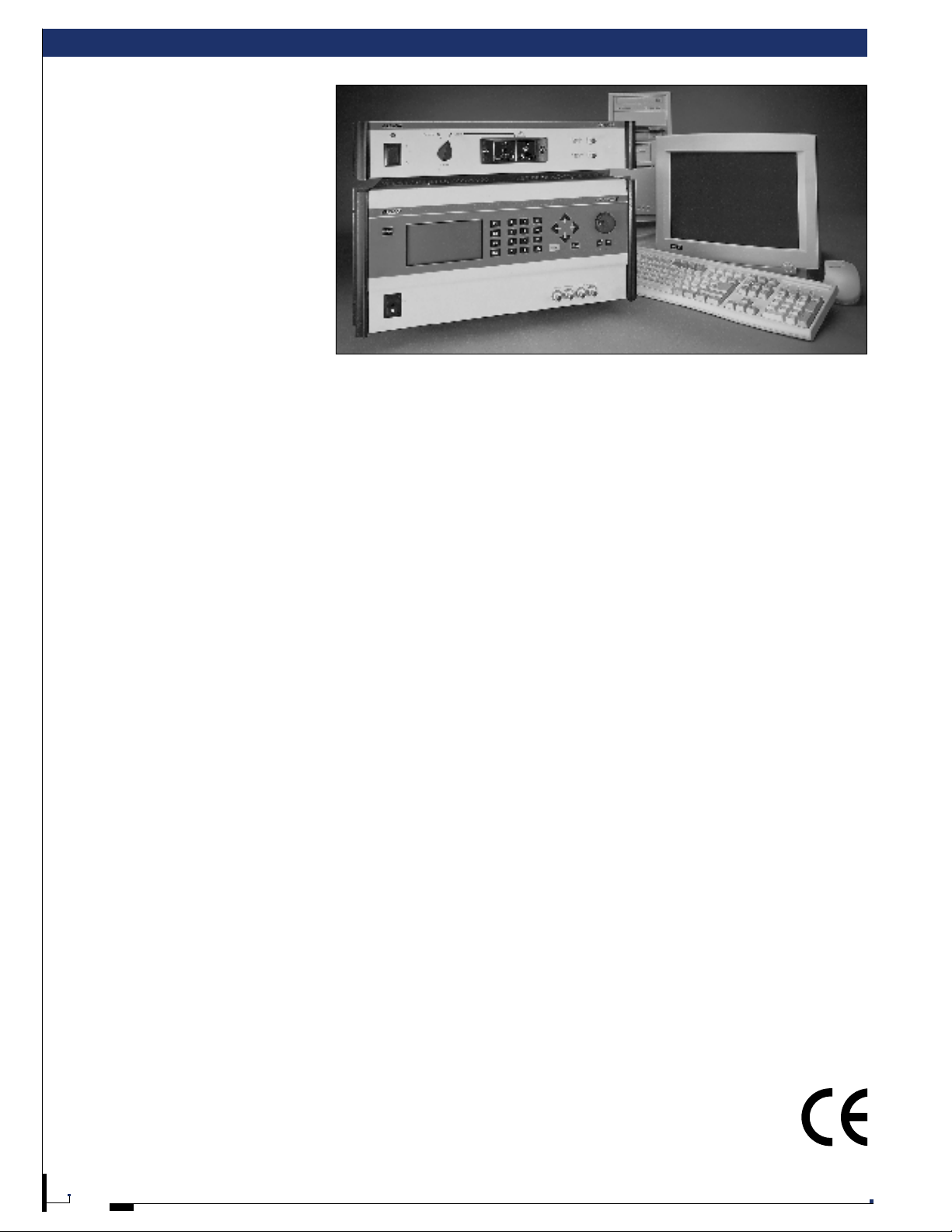
EUROPEAN STANDARD TESTER (EST)
PRODUCT OVERVIEW
The Elgar European Standards Tester (EST)
is a complete solution for harmonics and
flicker emissions compliance testing. The
system is controlled through a Windows
®
95/98 or NT User Interface which has been
designed for ease of use, the highest data
analyzing integrity and powerful test report
generation. Data analysis displays include
power analysis measurement and unique
graphs that assist in troubleshooting your
equipment.
INTEGRATED EST
SYSTEM
The EST system incorporates Elgar’s
powerful SmartWave AC Power Source
(SWA E) and the PA 1000 Analyzer with
proprietary applications software to deliver
the most accurate harmonic and flicker
compliance testing analysis and reporting.
It also can be used as a stand alone power
analyzer.
FEATU RE S AND
BE N E FITS
■
SmartWave SWAE AC Power Source
with low impedance, 1750 VA,
3700 VA (16A at 230 VAC out) or
5250 VA single phase output power
■
DSP base d PA 1000 Analyzer for
harmonics and flicker analysis and
power measurements
■
User interface software with
comprehensive diagnostics, displays,
and report generator ready to operate
with other applications in any
Windows®95/98 or NT environment
■
Optional Discrete Reference Impedance
The Elgar European Standard Tester (EST)
was designed for quick set-up, flexibility
and strict compliance to the standards.
Incorporating these features into the EST
offers users many advantages including:
■
Wizard Set-Up Screens: Guide
the user through the set-up process
using a standard Wizard format
■
On-line Context Sensitive Help:
Quickly helps the user configure any
test with little or no test experience,
using such tools as an on-line
manual, tool-tips and a “what is
this?” button
■
Flexible User Interface: Displays test
data in graphical and tabular forms
■
Unique Analysis Displays: Helps
the user efficiently troubleshoot the
equipment under test
■
Reporting with Tables and Charts:
Prints standard short and long
form reports
■
Data Integrity: Constant self-test
and self-monitoring ensures “no
gaps or overlaps” as required in
EN 61000-3-2 Annex B.4.2,
paragraph A.
■
Compliant AC Source: The output of
the SWA E is monitored to ensure it
meets the AC source requirements.
■
Immunity Testing: The SWAE
generates waveforms required by
EN 61000-4-13,-4-14,-4-28, 4-17,
and pre-compliance only for 4-11
Elgar has designed the European
Standards Tester (E ST) for maximum
versatility and ease of use. The systems are
completely integrated for quick start-up
and short operator learning curves. User
friendly features like automatic class A/D
test selection eliminate confusion and
speed testing. All of these systems and
their components are backed by Elgar’s 35
year commitment to supplying optimum AC
test power solutions.
THE EUROP EAN STANDARD S T E ST E R
(EST) I S IDEAL FOR:
Testing Services requiring simple
operation with high throughput test
capability for certifying product compliance
to European standards
Manufacturers requiring programmable
AC power test equipment for certifying
compliance to European standards
Development Laboratories requiring
versatile programmable AC power test
equipment for harmonic and flicker
measurement as well as custom waveform
generation
System Integrators who are required to
prove compliance for complete systems
European Standards Tester
Page 2
Elgar ■1.800.733.5427 ■858.450.0085 ■Fax 858.458.0267 ■9250 Brown Deer Road, San Diego, CA 92121 ■www.elgar.com ■email: sales@elgar.com
17
EUROPEAN STANDARDS TESTER (EST)
PA 1000
Unique among analyzer systems, the EST
Series PA 1000 performs all measurements
and real-time digital signal processing. The
PC is only used to display the User
Interface which provides control of the
equipment. Other key features of the
analyzer are:
■
Sampling rate of 175,000 samples/s
■
18 bit A-to- D converters
■
24 bit/80 MI P S real-time DSP
■
Optional Discrete Reference
Impedance
■
No range switching required to
measure the full 16 amp range
■
Continuous AC power source
monitoring
■
Front or rear panel EUT p ower
connections
■
Flickermeter complies with EN 86 8
and EN 61000-4-15
■
1 year calibration interval
The PA 1000 offers full compliance with
on-board, self contained, computation.
The PA 1000 digital signal processor
performs all computations including
filtering, weighing, FFT’s and DF T’s.
SET-UP
Simple start-up windows provide easy test
set-up fields and EST system control. Each
test configuration can be rerun from the
test template screen and is stored as part
of a test log history file. Class selection
includes A, B, C and D and an auto A/ D
feature that enables the analyzer to classify
the equipment during the test. All data is
exportable to spreadsheet applications.
HARMO NICS (EN 61000-3-2)
The harmonics graphs and tables are
updated continuously during the test. The
harmonic bar chart displays the harmonic
content of the EUT as well as displaying
the limit for each harmonic specified by the
standard. Absolute and relative harmonic
measurements can be displayed
simultaneously. Worst case measurements
are stored throughout the test and
displayed with pass/fail designation.
The PA 1000 meets the exact requirements
of the EN 61000-3-2, as described in
Annex B.4.2.
Annex B.4.2 Additional requirements for all other
cases, including fluctuating harmonics
a) There shall be no gap, and no overlapping between
successive measuring windows for rectangular
(“uniform”) windows.
FLIC K E R (EN 61000-3-3)
Pt plot displays the distribution of
instantaneous flicker values. An
innovative dt distribution graph assists
the user in troubleshooting the equipment
under test. This plot displays the
distribution of voltage deviations.
IMMUNITY TESTING
The EST’s AC source generates waveforms
compliant with the following immunity test
standards:
EN 61000-4-11 Voltage Dips, Short
Interruptions and Voltage
Variations (Pre-Compliance)
EN 61000-4-13 Harmonics, Interharmonics
including Mains Signaling
at AC Powerport –
Immunity Test
EN 61000-4-14 Voltage Fluctuation –
Immunity Test
EN 61000-4-17Ripple on DC Input Power
Port – Immunity Test
EN 61000-4-28 Variation of the Power
Frequency - Immunity Test
The EST’s User Interface includes test
routines for each of these immunity tests.
The tests can be executed following a
simple wizard format. All test parameters
can be changed. During all immunity tests
three charts are plotted continually (plot
points updated ever y 1.5 seconds, user
adjustable) for frequency, VRMS and IRMS .
The short form report contains pass/fail,
calibration data and test configuration (the
minimum information typically required by
regulatory agencies).
Sampling data is provided for harmonics
and flicker, worst case values, and other
data that is useful for troubleshooting and
maintaining historical records for
equipment designers.
IMMUNITY TEST REPORTS
Reports are also generated for the
immunity tests. After each test sequence is
run a note pad screen is automatically
generated. This note pad stores the
operator’s comments and observations for
each sequence. These notes are
automatically logged in the test report in
the test and sequence order. Reports also
contain all test configuration data fields.
Reports and all test data may be downloaded for spreadsheet applications for
maximum user versatility.
Note: For more information on the SWAE see page 15.
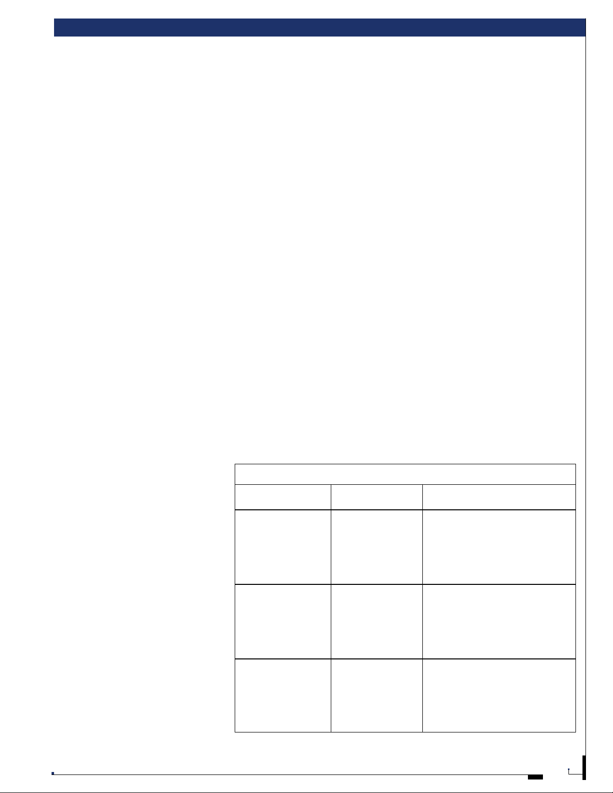
Ordering Information
Model Output Power AC Input
Rating
EST 1750-1 1750 VA
1
187-264VRMS (L- L), 3 wire
EST 1750-2 1750 VA
1
342-457VRMS (L- L), 4 w ire
EST 1750-3* 1750 VA
1
187-264VRMS (L- L), 3 wire
EST 1750-4* 1750 VA
1
342-457VRMS (L- L), 4 w ire
230 V L-N, Single Phase, 3 wire
EST 3700-1 3700 VA
2
187-264VRMS (L- L), 3 wire
EST 3700-2 3700 VA
2
342-457VRMS (L- L), 4 w ire
EST 3700-3* 3700 VA
2
187-264VRMS (L- L), 3 wire
EST 3700-4* 3700 VA
2
342-457VRMS (L- L), 4 w ire
230 V L-N, Single Phase, 3 wire
EST 5250-1 5250 VA
3
187-264VRMS (L- L), 3 wire
EST 5250-2 5250 VA
3
342-457 VRMS (L- L), 4 w ire
EST 5250-3* 5250 VA
3
187-264VRMS (L- L), 3 wire
EST 5250-4* 5250 VA
3
342-457VRMS (L- L), 4 w ire
230 V L-N, Single Phase, 3 wire
* Power factor corrected
1
1495 VA at 230V output
2
3680 VA at 230V output34485 VA at 230V output
Any model can be ordered with the optional discrete reference impedance in addition to the standard synthesized impedance.
 Loading...