

Page 1
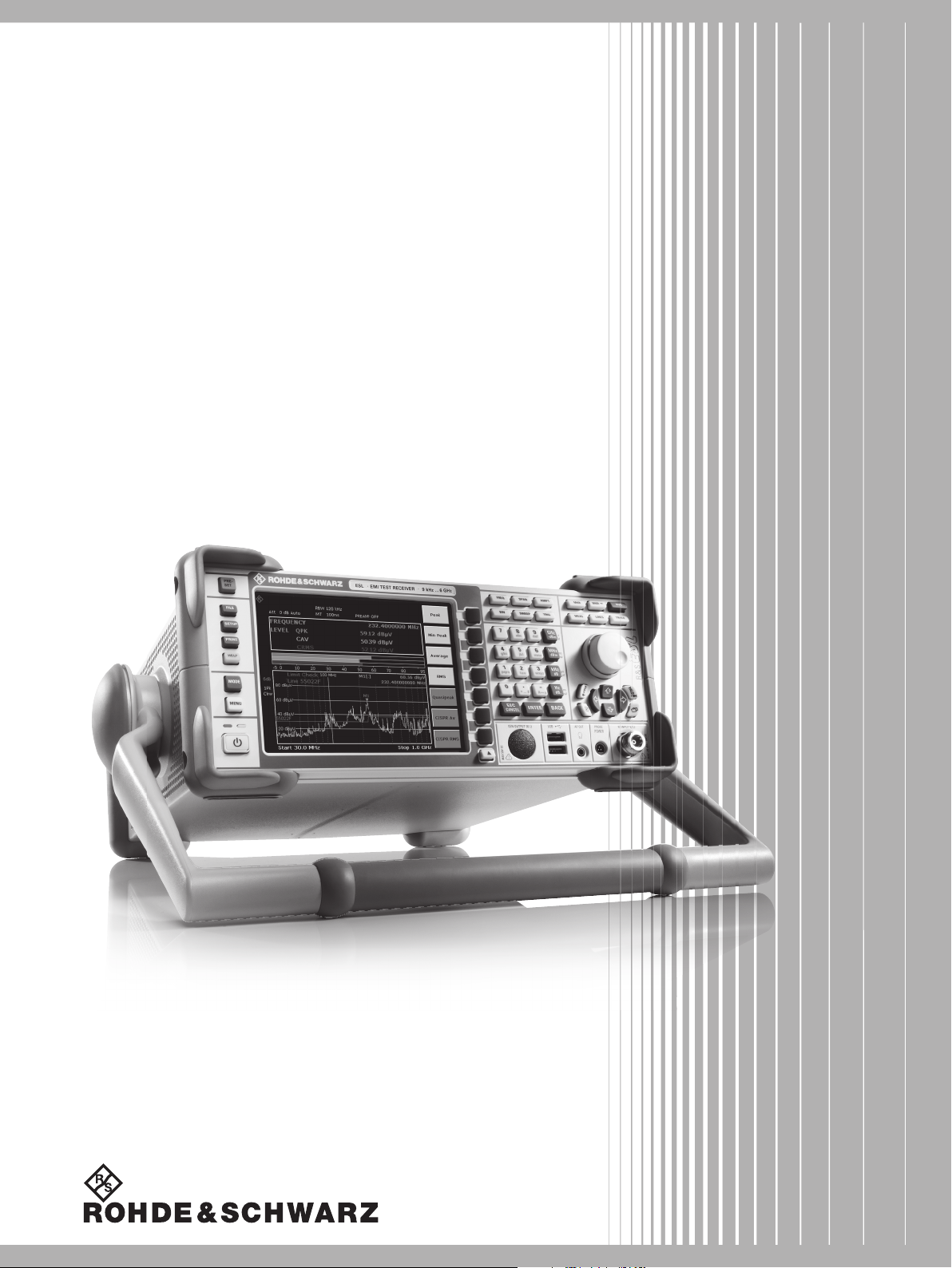
R&S®ESL
EMI Test Receiver
Specifications
Data Sheet | 02.00
Test & Measurement
Page 2

Version 02.00, March 2013
CONTENTS
Specifications .................................................................................................................................................................. 3
Frequency ............................................................................................................................................................................................... 3
Receiver scan ......................................................................................................................................................................................... 3
Sweep time ............................................................................................................................................................................................. 3
IF and resolution bandwidths .................................................................................................................................................................. 4
Level ....................................................................................................................................................................................................... 5
Trigger functions ..................................................................................................................................................................................... 8
I/Q data ................................................................................................................................................................................................... 8
Inputs and outputs .................................................................................................................................................................................. 8
General data ........................................................................................................................................................................................... 9
R&S®FSL-B5 additional interfaces ........................................................................................................................................................ 10
R&S®FSL-K7 AM/FM/φM measurement demodulator .......................................................................................................................... 11
R&S®FSL-K30 application firmware for noise figure and gain measurements ..................................................................................... 13
Frequency ......................................................................................................................................................................................... 13
Noise figure and gain measurement ................................................................................................................................................. 13
Required hardware ............................................................................................................................................................................ 13
Ordering information .................................................................................................................................................... 14
Options .................................................................................................................................................................................................. 14
Recommended extras ........................................................................................................................................................................... 14
Power sensors supported by the R&S®FSL-K9 .................................................................................................................................... 15
Specifications apply under the following conditions:
15 minutes warm-up time at ambient temperature, specified environmental conditions met, calibration cycle adhered to.
Data without tolerances: typical values only. Data designated 'nominal' applies to design parameters and is not tested.
Rohde & Schwarz equipment is designed for reliable operation up to an altitude of 3000 m above sea level, and for transport up to an
altitude of 4600 m above sea level.
2 Rohde & Schwarz R&S
®
ESL EMI Test Receiver
Page 3
Version 02.00, March 2013
–
–
–
–
–
–
Specifications
Specifications apply under the following conditions:15 minutes warm-up time at ambient temperature, specified environmental
conditions met, calibration cycle adhered to. Data without tolerances: typical values only. Data designated 'nominal' applies to design
parameters and is not tested. Rohde & Schwarz equipment is designed for reliable operation up to an altitude of 3000 m above sea
level, and for transport up to an altitude of 4600 m above sea level.
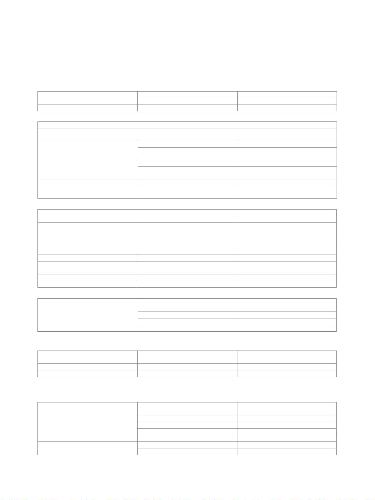
Frequency
Frequency range R&S®ESL3 9 kHz to 3 GHz
R&S®ESL6 9 kHz to 6 GHz
Frequency resolution 1 Hz
Reference frequency, internal
Accuracy (time since last adjustment × aging rate) +
temperature drift + calibration accuracy
1 × 10
1 × 10
5 × 10
6
7
6
7
7
8
Aging per year standard 1 × 10
with R&S®FSL-B4 OCXO reference
frequency option
Temperature drift (+5 °C to +45 °C) standard 1 × 10
with R&S®FSL-B4 OCXO reference
frequency option
Max. initial calibration accuracy standard 5 × 10
with R&S®FSL-B4 OCXO reference
frequency option
Frequency readout
Marker resolution 1 Hz
Uncertainty ±(marker frequency × reference
uncertainty + 10 % × resolution bandwidth
+ ½ (span / (sweep points – 1)) + 1 Hz)
Marker tuning frequency step size default
marker step size = sweep points
span / 500
span / (sweep points – 1)
Frequency counter resolution 1 Hz
Count uncertainty S/N > 25 dB ±(frequency × reference uncertainty +
½ (last digit))
Frequency span 0 Hz, 10 Hz to 3/6 GHz
Span uncertainty 3 %
Spectral purity SSB phase noise f = 500 MHz
Carrier offset 1 kHz typ. –95 dBc (1 Hz)
10 kHz <–98 dBc (1 Hz), typ. –103 dBc (1 Hz)
100 kHz <–98 dBc (1 Hz), typ. –105 dBc (1 Hz)
1 MHz <–115 dBc (1 Hz), typ. –120 dBc (1 Hz)
Receiver scan
Scan scan with max. 10 subranges with
different settings
Measurement time per frequency 100 µs to 100 s
Number of measurement points 1000000 per trace
Sweep time
Range span = 0 Hz 1 µs to 5 µs in 125 ns steps
10 Hz ≤ span ≤ 3.2 kHz 2.5 ms to 5 s/Hz × span
3.2 kHz < span ≤ 1.5 GHz 2.5 ms to 16000 s
1.5 GHz < span ≤ 3 GHz 5 ms to 16000 s
span > 3 GHz 10 ms to 16000 s
Uncertainty span = 0 Hz nominal 0.1 %
span ≥ 10 Hz nominal 3 %
Rohde & Schwarz R&S
5 µs to 16000 s in 5 % steps
®
ESL EMI Test Receiver 3
Page 4
Version 02.00, March 2013
IF and resolution bandwidths
IF filter and sweep filters
3 dB bandwidths 10 Hz to 10 MHz in 1/3 sequence
receiver mode and zero span 20 MHz additionally
Bandwidth uncertainty nominal <3 %
Shape factor 60 dB:3 dB nominal <5 (Gaussian type filters)
EMI filters
6 dB bandwidths 200 Hz, 9 kHz, 120 kHz, 1MHz
Bandwidth uncertainty nominal <3 %
Shape factor 60 dB:3 dB nominal <6
FFT filters (analyzer mode only)
3 dB bandwidths 1 Hz to 30 kHz in 1/3 sequence
Bandwidth uncertainty nominal 5 %
Shape factor 60 dB:3 dB nominal 2.5
Channel filters
Bandwidths 100, 200, 300; 500 Hz;
1; 1.5; 2; 2.4; 2.7; 3; 3.4; 4; 4.5; 5; 6; 8.5; 9 kHz
10; 12.5; 14; 15; 16; 18 (RRC); 20; 21; 24.3 (RRC); 25; 30; 50; 100; 150; 192; 200; 300;
500 kHz
1; 1.228; 1.28 (RRC); 1.5; 2; 3;3.84 (RRC); 4.096 (RRC); 5 MHz
(RRC = root raised cosine)
Video bandwidths (analyzer mode only) 1-pole lowpass RC filters 1 Hz to 10 MHz in 1/3 sequence
Signal analysis bandwidth nominal 28 MHz
4 Rohde & Schwarz R&S
®
ESL EMI Test Receiver
Page 5
Version 02.00, March 2013
Level
Display range displayed noise floor to +20 dBm
Maximum rated input level
DC voltage 50 V
CW RF power 30 dBm (= 1 W)
Peak RF power 36 dBm (= 4 W) <3 s
Max. pulse voltage 150 V
Max. pulse energy pulse width 10 µs 10 mWs
Intermodulation
Third-order intermodulation intermodulation-free dynamic range, level 2 × –20 dBm, reference level –10 dBm
fin < 30 MHz >54 dBc (TOI +7 dBm, typ. +12 dBm)
fin ≥ 30 MHz >60 dBc (TOI +10 dBm, typ +18 dBm)
Second harmonic intercept (SHI) 20 MHz ≤ fin ≤ 3 GHz nominal +35 dBm
1 dB compression of input mixer 0 dB RF attenuation, preamplifier = OFF,
f > 200 MHz
Displayed average noise level (DANL, analyzer mode)
0 dB RF attenuation, termination 50 Ω, RBW = 1 kHz, VBW = 1 Hz,
sample detector, log scaling, tracking generator OFF, normalized to 1 Hz
frequency preamplifier = OFF
9 kHz to 1 MHz <–115 dBm (1 Hz)
1 MHz to 10 MHz <–120 dBm (1 Hz)
10 MHz to 50 MHz <–130 dBm (1 Hz)
50 MHz to 3 GHz <–140 dBm (1 Hz)
3 GHz to 5 GHz <–136 dBm (1 Hz)
5 GHz to 6 GHz <–130 dBm (1 Hz)
with R&S®FSL-B22 option
frequency preamplifier = ON
9 kHz to 1 MHz <–130 dBm (1 Hz)
1 MHz to 10 MHz <–135 dBm (1 Hz)
10 MHz to 50 MHz <–145 dBm (1 Hz)
50 MHz to 3 GHz <–152 dBm (1 Hz)
3 GHz to 5 GHz <–146 dBm (1 Hz)
5 GHz to 6 GHz <–140 dBm (1 Hz)
frequency preamplifier = ON, typical values
500 MHz –162 dBm (1 Hz)
1 GHz –160 dBm (1 Hz)
3 GHz –158 dBm (1 Hz)
6 GHz –147 dBm (1 Hz)
nominal +5 dBm
Rohde & Schwarz R&S
®
ESL EMI Test Receiver 5
Page 6

Version 02.00, March 2013
Noise indication (receiver mode, nominal values, calculated from DANL data)
RF attenuation = 0 dB, termination = 50 Ω, average (AV) detector,
tracking generator = OFF
frequency preamplifier = OFF
9 kHz to 150 kHz, BW = 200 Hz <15 dBµV
150 kHz to 1 MHz, BW = 9 kHz <32 dBµV
1 MHz to 10 MHz, BW = 9 kHz <27 dBµV
10 MHz to 30 MHz, BW = 9 kHz <17 dBµV
30 MHz to 50 MHz, BW = 120 kHz <28 dBµV
50 MHz to 1 GHz, BW = 120 kHz <18 dBµV
1 GHz to 3 GHz, BW = 1 MHz <27 dBµV
3 GHz to 5 GHz, BW = 1 MHz <31 dBµV
5 GHz to 6 GHz, BW = 1 MHz <37 dBµV
with R&S®FSL-B22 option
frequency preamplifier = ON
9 kHz to 150 kHz, BW = 200 Hz <0 dBµV
150 kHz to 1 MHz, BW = 9 kHz <17 dBµV
1 MHz to 10 MHz, BW = 9 kHz <12 dBµV
10 MHz to 30 MHz, BW = 9 kHz <2 dBµV
30 MHz to 50 MHz, BW = 120 kHz <13 dBµV
50 MHz to 1 GHz, BW = 120 kHz <6 dBµV
1 GHz to 3 GHz, BW = 1 MHz <15 dBµV
3 GHz to 5 GHz, BW = 1 MHz <21 dBµV
5 GHz to 6 GHz, BW = 1 MHz <27 dBµV
frequency preamplifier = ON, typical values
500 MHz, BW = 120 kHz <–4dBµV
1 GHz, BW = 120 kHz <–2 dBµV
3 GHz, BW = 1 MHz <9 dBµV
6 GHz, BW = 1 MHz <20dBµV
Increase of DANL relative to AV display max. peak typ. +11 dB
RMS typ. +1 dB
quasi peak
band A typ. +3 dB
band B typ. +4 dB
bands C and D typ. +6 dB
Spurious responses
Image response fin – 2 × 48.375 MHz <–80 dBc, typ. –90 dBc
fin – 2 × 838.375 MHz <–80 dBc, typ. –90 dBc
fin – 2 × 7158.375 MHz typ. –60 dBc
Intermediate frequency response 48.375 MHz, 838.375 MHz,
<–60 dBc, typ. –80 dBc
7158.375 MHz
Residual spurious response f > 30 MHz, without input signal,
<–90 dBm
RF attenuation = 0 dB, RBW ≤ 10 kHz
Local oscillator related spurious response offset from carrier <100 kHz typ. –60 dBc
offset from carrier ≥100 kHz <–60 dBc
Other interfering signals:
A/D conversion related spurious
typ. <–70 dBc
response
Subharmonic of 1st LO spur at 7158.375 MHz – 2 × fin typ. –60 dBc
Harmonic of 1st LO mixer level <–10 dBm
(spur at f
– 3579.1875 MHz)
in
typ. –60 dBc
6 Rohde & Schwarz R&S
®
ESL EMI Test Receiver
Page 7

Version 02.00, March 2013
Level display (analyzer mode)
Logarithmic level axis 10 dB to 100 dB
Linear level axis 0 % to 100 %/10 divisions
Number of traces 4
Trace detectors max. peak, min. peak, auto peak, sample,
RMS, CISPR-AV, CISPR-RMS quasi
peak, average
Number of measurement points default value 501
range 125 to 32001
Trace functions clear/write, max. hold, average, min. hold,
Setting range of reference level logarithmic level display –80 dBm to 20 dBm
linear level display –80 dBm to 20 dBm, 0 % to 100 %
Units of level axis logarithmic level display dBm, dBmV, dBµV, dBµA, dBpW
linear level display µV, mV, V, µA, mA, A, pW, nW, µW, mW,
Level display (receiver mode)
Screen bargraph display + diagram
Level display digital numeric; 0.01 dB resolution
analog bargraph display, separately for each
Detectors max. 4 selectable max. peak, min. peak, RMS, average,
EMI detectors quasi peak, CISPR-AV, CISPR-RMS weighting in line with CISPR 16-1-1
Measurement time selectable 50 µs to 100 s
Units of level axis logarithmic level display dBm, dBµV, dBmV, dBµA, dBpW, dBpT
RF spectrum
Logarithmic level axis 10 dB to 200 dB, in steps of 10
Frequency axis selectable linear or logarithmic
Number of traces 6
in steps of about a factor of 2
view
in steps of 2 dB, 5 dB or 10 dB
W
detector
CISPR-AV, CISPR-RMS, quasi peak
Level measurement uncertainty
95 % confidence level, +20 °C to +30 °C,
S/N >16 dB, 0 dB to –50 dB from
reference level
10 MHz < f ≤ 3 GHz <0.5 dB
3 GHz < f ≤ 6 GHz <0.8 dB
Absolute uncertainty at 65.83 MHz <0.3 dB
Frequency response (+20 °C to +30 °C) 9 kHz ≤ f < 30 kHz nominal 1.5 dB
30 kHz ≤ f ≤ 3 GHz <0.5 dB, typ. 0.3 dB
3 GHz < f ≤ 6 GHz <0.8 dB, typ. 0.3 dB
Attenuator uncertainty <0.3 dB
Uncertainty of reference level setting nominal <0.1 dB
Display nonlinearity
Logarithmic level display S/N >16 dB
0 dB to –50 dB
Bandwidth switching uncertainty reference: RBW = 10 kHz nominal <0.1 dB
<0.2 dB
Rohde & Schwarz R&S
®
ESL EMI Test Receiver 7
Page 8

Version 02.00, March 2013
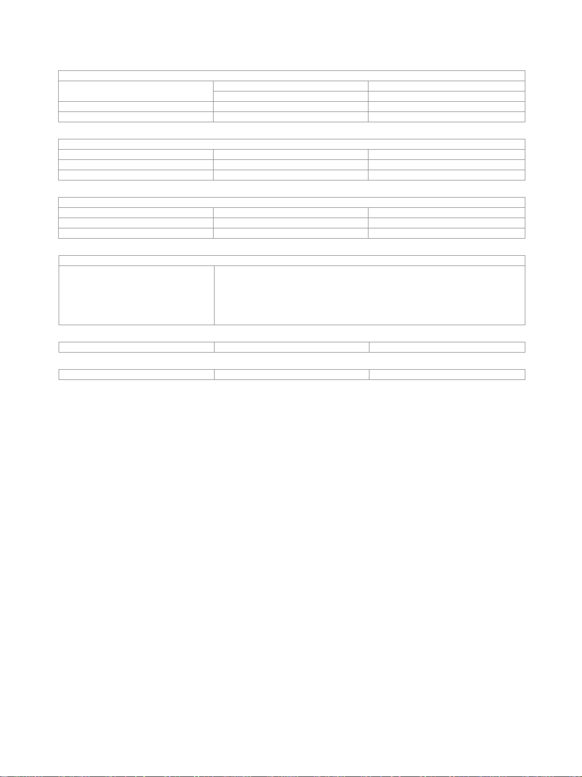
Trigger functions
Trigger
Trigger source free run, video, external, IF power
External trigger level TTL level
I/Q data
Interface LAN
R&S®FSL-B10 LAN or GPIB
Memory length max. 512 ksample I and Q
Sample rate 10 kHz to 65.8 MHz
Signal bandwidth sample rate 65.8 MHz nominal 28 MHz
Inputs and outputs
RF input
Impedance 50 Ω
Connector N female
VSWR RF attenuation ≥ 10 dB
10 MHz ≤ f ≤ 1 GHz nominal 1.2
1 GHz < f ≤ 6 GHz nominal 1.5
Input attenuator 0 dB to 50 dB in 5 dB steps
AF output
Connector 3.5 mm mini jack
Output impedance <100 Ω
Open-circuit voltage up to 1.5 V, adjustable
Tracking generator
Tracking generator models .13 and .16 only N female, 50 Ω
Output level –50 dBm to 0 dBm in 1 dB steps
Frequency range 1 MHz to 3 GHz/6 GHz
Dynamic range RF attenuation = 0 dB, source power 0 dBm
10 MHz to 2 GHz nominal 80 dB
2 GHz to f
Reverse power
DC voltage 50 V
CW RF power 30 dBm (= 1 W)
Max. pulse voltage 150 V
Max. pulse energy (10 µs) 10 mWs
External reference
Connector BNC female, 50 Ω
Input level 0 dBm to +10 dBm
Output level with R&S®FSL-B4 typ. 0 dBm
Frequency 10 MHz ±5 ppm
External trigger/gate input
Connector BNC female, 50 Ω
Input level TTL-compatible
Probe power
+15 V DC, –12.6 V DC and ground,
nominal 60 dB
max
max. 150 mA, nominal
External monitor
Connector VGA
®
8 Rohde & Schwarz R&S
ESL EMI Test Receiver
Page 9

Version 02.00, March 2013
–
General data
Remote control
LAN interface 10/100BaseT, RJ-45
IEC/IEEE bus (GPIB) R&S®FSL-B10 SCPI 1997.0
Display
Resolution 640 × 480 pixels
Pixel failure rate <2 × 10
Mass memory
Mass memory flash disk (internal), USB memory stick
Data storage >500 instrument settings and traces
Temperature
Operating temperature range +0 °C to +50 °C
Permissible temperature range +0 °C to +55 °C
Storage temperature range –40 °C to +70 °C
Climatic loading +25 °C/+40 °C at 85 % relative humidity
Mechanical resistance
Vibration sinusoidal IEC 60068-2-6
random IEC 60068-2-64
Shock 40 g shock spectrum,
5
(not supplied)
(IEC 60068-2-30)
in line with MIL-STD-810E, method 516.4
procedure 1, IEC 60068-2-27
Power supply
Input voltage range, AC, nominal 100 V to 240 V
AC supply frequency 50 Hz to 400 Hz
Input current, AC 0.9 A to 0.3 A
Input voltage range, DC, nominal R&S®FSL-B30 10 V to 28 V
Input current, DC R&S®FSL-B30 8.0 A to 2.2 A
Power consumption typ. 45 W, max. 65 W with all options
Safety IEC 61010-1, EN 61010-1, UL 61010B-1,
CSA C22.2 No. 1010-1
Test mark VDE, GS, CSA, CSA-NRTL
EMC EMC Directive 2004/108/EC including:
EN 61326 class B (emission)
CISPR 11/EN 55011/group 1
class B (emission)
EN 61326 table A.1 (immunity,
industrial)
Dimensions (W × H × D) with handle 408.8 mm × 158.1 mm × 465.3 mm
(16.09 in × 6.22 in × 18.32 in)
without handle 342.3 mm × 158.1 mm × 367.0 mm
(13.48 in × 6.22 in × 14.45 in)
Weight without options <7 kg (<15.43 lb)
with battery pack <8 kg (<17.64 lb)
Recommended calibration interval 1 year
operation with external reference 2 years
®
Rohde & Schwarz R&S
ESL EMI Test Receiver 9
Page 10

Version 02.00, March 2013
R&S®FSL-B5 additional interfaces
User port
Connector 9-pin D-Sub male
Output TTL-compatible, 0 V/5 V max. 15 mA
Input TTL-compatible, max. 5 V
Noise source control
Connector BNC female
Output 0 V/28 V, max. 100 mA, switchable,
supply for noise source
Power sensor
Connector 6-pin LEMOSA female for supported
IF/video out
Connector BNC female, 50 Ω
IF out
Bandwidth nominal 28 MHz
IF frequency RBW 20 MHz,
center frequency >20 MHz, span 0 Hz
Output level (gain versus RF input) RF attenuation 0 dB, RF preamplifier = OFF, span 0 Hz, RBW 20 MHz
center frequency
100 MHz approx. +3 dB
3 GHz approx. –1 dB
6 GHz approx. –7 dB
Video out
Bandwidth equal to VBW setting, max. RBW/2
Output scaling log scaling with display scale set to log,
Output level center frequency >10 MHz, span 0 Hz, signal at reference level and center frequency
video 1 V 1 V ±10 % (open circuit) (nominal)
video 200 mV 200 mV ±10 % (open circuit) (nominal)
®
NRP-Zxx power sensors
R&S
17.45833 MHz (nominal) ±2 MHz,
dependent on center frequency
lin scaling with display scale set to lin
10 Rohde & Schwarz R&S
®
ESL EMI Test Receiver
Page 11

Version 02.00, March 2013
R&S®FSL-K7 AM/FM/φM measurement demodulator
Measurement of analog modulation signals
Demodulation bandwidth 100 Hz to 6.4 kHz, binary steps
12.5 kHz to 1.6 MHz, binary steps
3 MHz, 5 MHz, 8 MHz, 10 MHz, 18 MHz
Recording length maximum 512 ksample
Recording time demodulation bandwidth
100 Hz 3276.8 s
6.4 kHz 51.2 s
12.5 kHz 26.6 s
1.6 MHz 200 ms
3 MHz 100 ms
5 MHz 50 ms
8 MHz 25 ms
10 MHz 12.5 ms
18 MHz 12.5 ms
Display frequency versus time (FM), amplitude versus time (AM), phase versus time (φM),
AF (modulation frequency)
Range
Resolution 5 digits
Measurement uncertainty 0.1 %
AF filters
Lowpass 3 kHz, 15 kHz, 150 kHz,
Highpass 50 Hz, 300 Hz
Deemphasis 25 µs, 50 µs, 75 µs, 750 µs
RF power versus time, RF spectrum (FFT), AF spectrum (FFT),
table with numeric values for: modulation deviation (peak, RMS), modulation
frequency, carrier offset, carrier power (power of unmodulated carrier), THD, SINAD
9 MHz
max. 0.5 × demodulation bandwidth
5 %, 10 %, 25 % of demodulation
bandwidth
AM demodulation
Measurement range modulation depth 0 % to 100 %
Modulation depth uncertainty AF 1 MHz <3 % of reading + residual AM
Residual AM demodulation bandwidth 200 kHz, RMS,
RF 3 GHz, RF input level
(RF attenuation/dB – 30) dBm
Distortion 10 Hz AF 100 kHz 0.3 %
FM rejection AF ≤ 1 MHz and
AF + deviation ≤ 0.5 × demodulation
bandwidth
FM demodulation
Measurement range frequency deviation
Deviation uncertainty AF ≤ 1 MHz and
AF + deviation ≤ 0.5 × demodulation
bandwidth
Residual FM demodulation bandwidth ≤100 kHz, RMS,
RF input level ≥ (RF attenuation/dB –30) dBm
RF ≤ 1 GHz 150 Hz
RF = 3 GHz 200 Hz
Distortion 10 Hz ≤ AF ≤ 100 kHz,
deviation < 400 kHz
AM rejection 100 Hz ≤ AF ≤ 1 kHz,
modulation depth 50 %
0.2 %
typ. 1 % + residual AM
9 MHz
<3 % of reading + residual FM
0.3 %
30 Hz
®
Rohde & Schwarz R&S
ESL EMI Test Receiver 11
Page 12

Version 02.00, March 2013
M demodulation
AF 5 MHz,
max. 0.5 × demodulation bandwidth
Measurement range phase deviation <1000 rad
Residual M demodulation bandwidth ≤100 kHz, RMS,
5 mrad
RF = 1 GHz, highpass 300 Hz,
RF input level ≥ (RF attenuation/dB
– 30 dBm)
Carrier power versus time
Display range noise floor to +20 dBm
Measurement uncertainty unmodulated carrier, S/N > 16 dB,
typ. 1 dB
RF: 50 kHz to 3 GHz
Maximum dynamic range demodulation bandwidth 200 kHz typ. 75 dB
Display linearity S/N > 16 dB typ. 0.2 dB
AF spectrum
Span
9 MHz
Resolution bandwidth 1 Hz to 10 MHz
RF spectrum
Span
18 MHz
Resolution bandwidth 1 Hz to 10 MHz
Shape factor 60 dB:3 dB 2.5, nominal
Modulation distortion
Measurement functions THD, SINAD
Measurement range –100 dB to 0 dB
Resolution 0.01 dB
Measurement uncertainty typ. 0.5 dB
AF frequency range 10 Hz to 5 MHz
Trigger
Trigger functions RF level, AM, FM, M demodulation
®
12 Rohde & Schwarz R&S
ESL EMI Test Receiver
Page 13

Version 02.00, March 2013
®
R&S®FSL-K30 application firmware for noise figure and gain measurements
Frequency
Frequency range R&S®ESL3 100 kHz to 3 GHz
R&S®ESL6 100 kHz to 6 GHz
Measurement bandwidth 10 Hz to 10 MHz (–3 dB) in 1/3 sequence
Noise figure and gain measurement
Noise figure
Measurement range 0 dB to 35 dB
Resolution 0.01 dB
Accuracy instrument uncertainty (95 % confidence level)
frequency range 100 kHz to 10 MHz
measurement with external preamplifier
(gain 50 dB, noise figure <5 dB),
RBW <10 kHz, DUT noise figure
1 dB to 10 dB and gain >10 dB
frequency range >10 MHz to 6 GHz
measurement with external preamplifier
(gain 30 dB, noise figure <5 dB),
RBW 1 MHz, DUT noise figure
1 dB to 10 dB and gain >10 dB
R&S®FSL-B22 (internal preamplifier)
active, measurement with external
preamplifier (gain 20 dB, noise figure
<5 dB),
RBW 1 MHz, DUT noise figure
1 dB to 10 dB and gain >10 dB
0.3 dB
0.3 dB
0.3 dB
Gain
Measurement range 0 dB to 60 dB
Resolution 0.01 dB
Accuracy frequency range 100 kHz to 10 MHz
measurement with external preamplifier
(gain 50 dB, noise figure <5 dB),
RBW <10 kHz
frequency range >10 MHz to 6 GHz
measurement with external preamplifier
(gain 30 dB, noise figure <5 dB),
RBW 1 MHz
0.2 dB
0.2 dB
Required hardware
Spectrum analyzer
Noise source supply via 28 V connector on rear panel of
Noise source recommendation NoiseCom NC346
Preamplifier, external frequency range 100 kHz to 3/6 GHz gain approx. 30 dB, noise figure max. 5 dB
R&S
®
FSL
R&S
FSL-B5
®
Rohde & Schwarz R&S
ESL EMI Test Receiver 13
Page 14

Version 02.00, March 2013
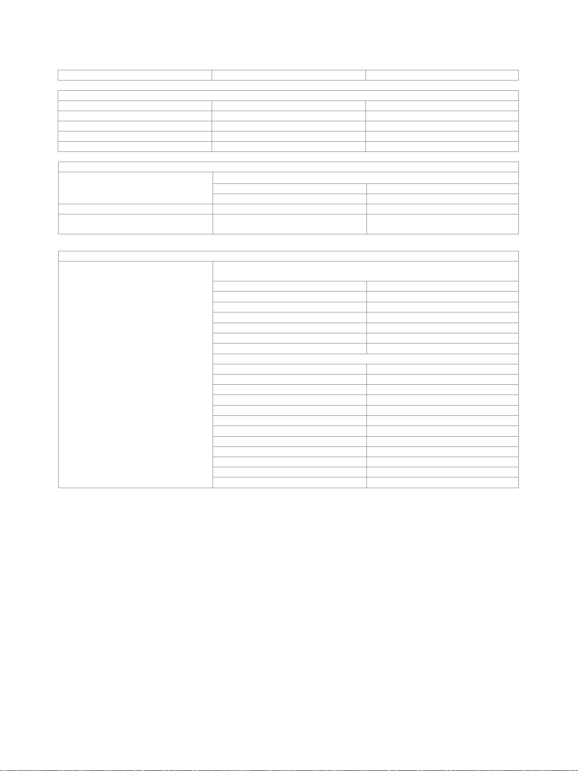
Ordering information
Designation Type Order No.
Test Receiver, 9 kHz to 3 GHz R&S®ESL3 1300.5001.03
Test Receiver, 9 kHz to 3 GHz,
with tracking generator
Test Receiver, 9 kHz to 6 GHz R&S®ESL6 1300.5001.06
Test Receiver, 9 kHz to 6 GHz,
with tracking generator
Accessories supplied
Power cable, quick start guide and CD-ROM (with operating manual and service manual)
Recommended extras
Printed manual (includes operating
manual and service manual)
Options
Designation Type Order No. Retrofittable Remarks
Options
OCXO Reference Frequency R&S®FSL-B4 1300.6008.02 yes
Additional Interfaces R&S®FSL-B5 1300.6108.02 yes video out, IF out, noise
Gated Sweep R&S®FSL-B8 1300.5701.02 yes
GPIB Interface R&S®FSL-B10 1300.6208.02 yes
RF Preamplifier (3/6 GHz) R&S®FSL-B22 1300.5953.02 yes
DC Power Supply R&S®FSL-B30 1300.6308.02 yes
NiMH Battery Pack R&S®FSL-B31 1300.6408.02 yes requires R&S®FSL-B30
Firmware/Software
AM/FM/φM Measurement Demodulator R&S®FSL-K7 1301.9246.02
Power Sensor Support R&S®FSL-K9 1301.9530.02 requires R&S®FSL-B5 or
Application Firmware for Noise Figure and
Gain Measurements
R&S®ESL3 1300.5001.13
R&S®ESL6 1300.5001.16
1300.5053.32
source control, AUX port,
®
NRP-Zx power
R&S
sensor
®
R&S
NRP-Z3/4
R&S®FSL-K30 1301.9817.02 requires R&S®FSL-B5 and
preamplifier
Recommended extras
Order designation Type Order No.
19’’ Rackmount Adapter R&S®ZZA-S334 1109.4487.00
Soft Carrying Bag R&S®FSL-Z3 1300.5401.00
Protective Hard Cover R&S®EVS-Z6 5201.7760.00
Additional Charger Unit R&S®FSL-Z4 1300.5430.02
Matching Pad 75 Ω, L section R&S®RAM 0358.5414.02
Matching Pad 75 Ω, series resistor 25 Ω R&S®RAZ 0358.5714.02
Matching Pad 75 Ω, L section, N to BNC R&S®FSH-Z38 1300.7740.02
14 Rohde & Schwarz R&S
®
ESL EMI Test Receiver
Page 15

Version 02.00, March 2013
Power sensors supported by the R&S®FSL-K9
Order designation Type Order No.
Average Power Sensor
10 MHz to 8 GHz, 200 mW
Average Power Sensor
10 MHz to 18 GHz, 200 mW
Average Power Sensor
10 MHz to 18 GHz, 2 W
Average Power Sensor
10 MHz to 18 GHz, 15 W
Average Power Sensor
10 MHz to 18 GHz, 30 W
Power Sensor Module with Power Splitter
DC to 18 GHz, 500 mW
Power Sensor Module with Power Splitter
DC to 26.5 GHz, 500 mW
Average Power Sensor
9 kHz to 6 GHz, 200 mW
Thermal Power Sensor
0 Hz to 18 GHz, 100 mW
Thermal Power Sensor
0 Hz to 40 GHz, 100 mW
Wideband Power Sensor
50 MHz to 18 GHz, 100 mW
R&S®NRP-Z11 1138.3004.02
R&S®NRP-Z21 1137.6000.02
R&S®NRP-Z22 1137.7506.02
R&S®NRP-Z23 1137.8002.02
R&S®NRP-Z24 1137.8502.02
R&S®NRP-Z27 1169.4102.02
R&S®NRP-Z37 1169.3206.02
R&S®NRP-Z91 1168.8004.02
R&S®NRP-Z51 1138.0005.02
R&S®NRP-Z55 1138.2008.02
R&S®NRP-Z81 1137.9009.02
Service options
Extended Warranty, one year R&S®WE1ESL Please contact your local Rohde
Extended Warranty, two years R&S®WE2ESL
& Schwarz sales office.
Extended Warranty, three years R&S®WE3ESL
Extended Warranty, four years R&S®WE4ESL
Extended Warranty with Calibration Coverage, one year R&S®CW1ESL
Extended Warranty with Calibration Coverage, two years R&S®CW2 ESL
Extended Warranty with Calibration Coverage, three years R&S®CW3 ESL
Extended Warranty with Calibration Coverage, four years R&S®CW4 ESL
Extended warranty with a term of one to four years (WE1 to WE4)
Repairs carried out during the contract term are free of charge
1
. Necessary calibration and adjustments carried out during repairs are
also covered. Simply contact the forwarding agent we name; your product will be picked up free of charge and returned to you in top
condition a couple of days later.
Extended warranty with calibration (CW1 to CW4)
Enhance your extended warranty by adding calibration coverage at a package price. This package ensures that your
Rohde & Schwarz product is regularly calibrated, inspected and maintained during the term of the contract. It includes all repairs
1
and
calibration at the recommended intervals as well as any calibration carried out during repairs or option upgrades.
For product brochure, see PD 5214.0430.12 and www.rohde-schwarz.com
1
Excluding defects caused by incorrect operation or handling and force majeure. Wear-and-tear parts are not included.
Rohde & Schwarz R&S
®
ESL EMI Test Receiver 15
Page 16

Service you can rely on
5214043022
❙ Worldwide
❙ Local and personalized
❙ Customized and flexible
❙ Uncompromising quality
❙ Long-term dependability
About Rohde & Schwarz
Rohde & Schwarz is an independent group of companies
specializing in electronics. It is a leading supplier of solutions in the fields of test and measurement, broadcasting,
radiomonitoring and radiolocation, as well as secure
communications. Established more than 75 years ago,
Rohde & Schwarz has a global presence and a dedicated
service network in over 70 countries. Company headquarters are in Munich, Germany.
Environmental commitment
J Energy-efcient products
J Continuous improvement in environmental sustainability
J ISO 14001-certied environmental management system
Cert ied Quali ty Syste m
ISO 9001
Rohde & Schwarz GmbH & Co. KG
www.rohde-schwarz.com
Regional contact
J Europe, Africa, Middle East | +49 89 4129 12345
customersupport@rohde-schwarz.com
J North America | 1 888 TEST RSA (1 888 837 87 72)
customer.support@rsa.rohde-schwarz.com
J Latin America | +1 410 910 79 88
customersupport.la@rohde-schwarz.com
J Asia/Pacic | +65 65 13 04 88
customersupport.asia@rohde-schwarz.com
J China | +86 800 810 8228/+86 400 650 5896
customersupport.china@rohde-schwarz.com
R&S® is a registered trademark of Rohde & Schwarz GmbH & Co. KG
Trade names are trademarks of the owners | Printed in Germany (as)
PD 5214.0430.22 | Version 02.00 | March 2013 | R&S®ESL
Subject to change
© 2008 - 2013 Rohde & Schwarz GmbH & Co. KG | 81671 München, Germany
 Loading...