

Page 1
R&S®ESCI/ESCI7
EMI Test Receiver
Specifications
Data Sheet | 03.00
Test & Measurement
Page 2
Version 03.00, June 2009
Specifications
Specifications apply under the following conditions: 15 minutes warm-up time at ambient temperature, specified environmental
conditions met, calibration cycle adhered to, and all internal automatic adjustments performed. Data without tolerances: typical values
only. Data designated 'nominal' applies to design parameters and is not assured by Rohde & Schwarz.
Frequency
Frequency range
Resolution
Internal reference frequency (nominal) standard
Aging per year after 30 days of continuous operation 1 × 10
Temperature drift +5 °C to +45 °C 1 × 10
Internal reference frequency (nominal) R&S
Aging per year after 30 days of continuous operation 1 × 10
Temperature drift +5 °C to +45 °C 1 × 10
External reference frequency 10 MHz
Frequency display (receiver mode) numeric display
Resolution 0.1 Hz
Frequency display (analyzer mode) with marker or frequency counter
Marker resolution span/500
Max. deviation sweep time > 3 × auto sweep time ±(marker frequency × reference frequency
Frequency counter resolution selectable 0.1 Hz to 10 kHz
Count accuracy S/N > 25 dB ± (marker frequency × reference
Display range of frequency axis R&S®ESCI 0 Hz, 10 Hz to 3 GHz
R&S®ESCI7 0 Hz, 10 Hz to 7 GHz
Max. deviation of display range 0.1 %
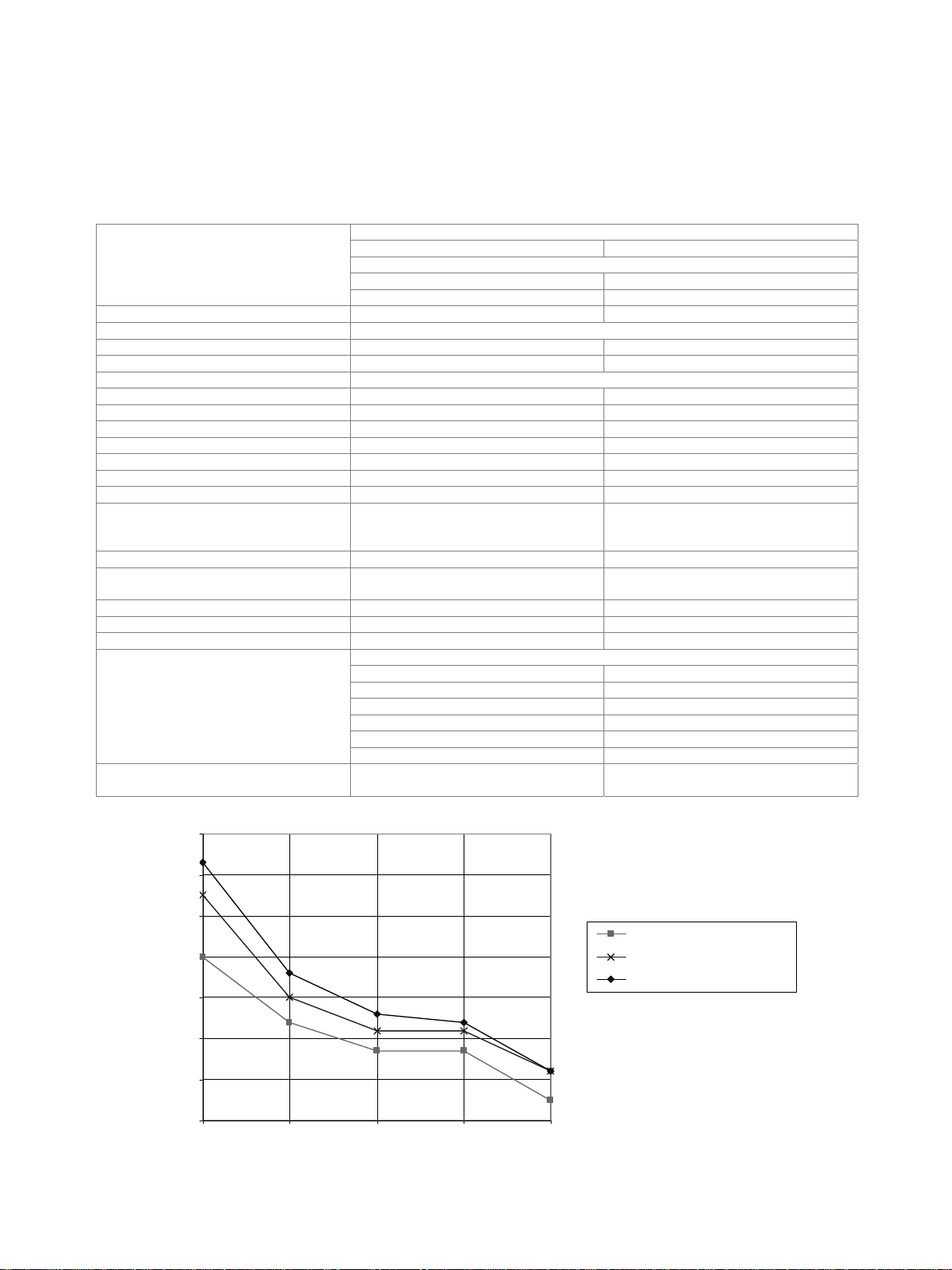
Spectral purity, SSB phase noise
Residual FM f = 500 MHz, RBW = 1 kHz,
R&S®ESCI
DC, AC coupled 9 kHz to 3 GHz
R&S®ESCI7
DC coupled 9 kHz to 7 GHz
AC coupled 1 MHz to 7 GHz
®
FSP-B4 option (OCXO)
0.01 Hz
–6
–6
–7
–8
error + 0.5 % × span + 10 % × resolution
bandwidth + ½ (last digit))
frequency error + ½ (last digit))
f = 500 MHz, for f > 500 MHz see diagram
100 Hz < –84 dBc (1 Hz), typ. –90 dBc (1 Hz)
1 kHz < –100 dBc (1 Hz), typ. –108 dBc (1 Hz)
10 kHz < –106 dBc (1 Hz), typ. –113 dBc (1 Hz)
100 kHz, span > 100 kHz < –110 dBc (1 Hz), typ. –113 dBc (1 Hz)
1 MHz, span > 100 kHz < –120 dBc (1 Hz), typ. –125 dBc (1 Hz)
10 MHz typ. –145 dBc (1 Hz)
typ. 3 Hz
sweep time = 100 ms
-60
-70
-80
-90
-100
-110
SSB phase noise (dBc(1Hz))
-120
-130
100 Hz 1 kHz 10 kHz 100 kHz 1 MHz
2 Rohde & Schwarz R&S
Typical phase noise at different center frequencies
®
ESCI/ESCI7 EMI Test Receiver
center frequency 500 MHz
center frequency 3 GHz
center frequency 7 GHz
Page 3
Version 03.00, June 2009
Scan (receiver mode)
Scan scan of max. 10 subranges with different,
Measurement time per frequency selectable 33 s to 100 s
independent settings
Sweep (analyzer mode)
Sweep time
Max. deviation of sweep time 1 %
in time domain, span = 0 Hz 1 s to 16000 s
resolution 125 ns
in frequency domain, span 10 Hz 2.5 ms to 16000 s
Resolution bandwidths
Sweep filters
3 dB bandwidths 10 Hz to 3 MHz, in steps of 1/3/10
100 kHz < 3 % Bandwidth accuracy
300 kHz to 3 MHz < 10 %
100 kHz < 5 Shape factor 60 dB:3 dB
300 kHz to 3 MHz < 15
6 dB bandwidths 200 Hz, 9 kHz, 120 kHz EMI bandwidths
pulse bandwidth 1 MHz
120 kHz < 3 % Bandwidth accuracy
1 MHz < 10 %
120 kHz < 5 Shape factor 60 dB:6 dB
1 MHz < 15
Video bandwidths analyzer mode 1 Hz to 10 MHz, in steps of 1/3/10
FFT filters analyzer mode
3 dB bandwidths 1 Hz to 30 kHz, in steps of 1/3/10
Bandwidth accuracy 5 %, nominal
Shape factor 60 dB:3 dB 2.5, nominal
Channel filters
Bandwidths 100/200/300/500 Hz;
1/1.5/2/2.4/2.7/3/3.4/4/4.5/5/6/8.5/9/
12.5/14/15/16/18 (RRC)/20/21/24.3 (RRC)/
25/30/50/100/150/192/200/300/500 kHz
1/1.228/1.28 (RRC)/1.5/2/3/3.84 (RRC)/
4.096 (RRC)/ 5 MHz
(RRC = root raised cosine)
10/
Preselection
Preselection can be switched off in analyzer mode R&S®ESCI: 11 preselection filters
Bandwidths (–6 dB), nominal R&S®ESCI, R&S®ESCI7
Preamplifier switchable, between preselection and
< 150 kHz 230 kHz, fixed-tuned lowpass filter
150 kHz to 2 MHz 2.6 MHz, fixed-tuned bandpass filter
2 MHz to 8 MHz 2 MHz, tracking bandpass filter
8 MHz to 30 MHz 6 MHz, tracking bandpass filter
30 MHz to 70 MHz 15 MHz, tracking bandpass filter
70 MHz to 150 MHz 30 MHz, tracking bandpass filter
150 MHz to 300 MHz 60 MHz, tracking bandpass filter
300 MHz to 600 MHz 80 MHz, tracking bandpass filter
600 MHz to 1 GHz 100 MHz, tracking bandpass filter
1 GHz to 2 GHz tracking highpass filter
2 GHz to 3 GHz fixed-tuned highpass filter
R&S®ESCI7
3 GHz to 7 GHz tracking bandpass filter
1st mixer
®
R&S
ESCI7: 12 preselection filters
20 dB
Rohde & Schwarz R&S
®
ESCI/ESCI7 EMI Test Receiver 3
Page 4
Version 03.00, June 2009
Level
Display range displayed average noise level (DANL)
Maximum input level
DC-coupled 0 V DC voltage
AC-coupled 50 V
RF attenuation 0 dB 20 dBm CW RF power
RF attenuation 10 dB 30 dBm
Pulse spectral density RF attenuation 0 dB 97 dBV/MHz
Max. pulse voltage RF attenuation 10 dB, 10 s 150 V
Max. pulse energy
Intermodulation
1 dB compression of input mixer f > 200 MHz, RF attenuation 0 dB,
Third-order intercept (TOI)
Second harmonic intercept (SHI)
R&S®ESCI
RF attenuation 10 dB, 20 s 10 mWs
R&S®ESCI7
RF attenuation 10 dB, 10 s 1 mWs
preselection and preamplifier off
RF attenuation 0 dB, level 2 × –30 dBm, f > 5 × RBW or 10 kHz, whichever is larger
without preselection, without preamplifier
R&S®ESCI, R&S®ESCI7
20 MHz to 200 MHz > 5 dBm
200 MHz to 3 GHz > 7 dBm, typ. 10 dBm
R&S®ESCI7
3 GHz to 7 GHz > 10 dBm, typ. 15 dBm
with preselection, without preamplifier
R&S®ESCI, R&S®ESCI7
20 MHz to 200 MHz > 0 dBm
200 MHz to 3 GHz > 2 dBm, typ. 5 dBm
R&S®ESCI7
3 GHz to 7 GHz > 10 dBm, typ. 15 dBm
with preselection, with preamplifier
R&S®ESCI, R&S®ESCI7
20 MHz to 200 MHz > –20 dBm
200 MHz to 3 GHz > –18 dBm, typ. –15 dBm
R&S®ESCI7
3 GHz to 7 GHz > –10 dBm, typ. –5 dBm
RF attenuation 0 dB, level –10 dBm, without preselection, without preamplifier
R&S®ESCI, R&S®ESCI7
< 100 MHz typ. 25 dBm
100 MHz to 1.5 GHz typ. 35 dBm
R&S®ESCI7
1.5 GHz to 3.5 GHz typ. 70 dBm
RF attenuation 0 dB, level –15 dBm, with preselection, without preamplifier
R&S®ESCI, R&S®ESCI7
4 MHz to 100 MHz > 40 dBm
100 MHz to 1.5 GHz > 50 dBm
R&S®ESCI7
1.5 GHz to 3.5 GHz typ. 70 dBm
RF attenuation 0 dB, level –35 dBm, with preselection, with preamplifier
R&S®ESCI, R&S®ESCI7
4 MHz to 100 MHz > 25 dBm
100 MHz to 1.5 GHz > 35 dBm
R&S®ESCI7
1.5 GHz to 3.5 GHz typ. 10 dBm
to 30 dBm
5 dBm, nominal
4 Rohde & Schwarz R&S
®
ESCI/ESCI7 EMI Test Receiver
Page 5

Version 03.00, June 2009
Displayed average noise level (DANL)
(analyzer mode)
RF attenuation 0 dB, RBW = 10 Hz,
VBW = 1 Hz, span = 0 Hz, trace average function over 20 sweeps, 50 termination
without preselection, without preamplifier, AC-coupled
R&S®ESCI
9 kHz < –105 dBm, nominal
100 kHz < –110 dBm, nominal
1 MHz < –130 dBm, nominal
10 MHz to 1 GHz < –142 dBm, typ. –145 dBm
1 GHz to 2.5 GHz < –140 dBm, typ. –143 dBm
2.5 GHz to 3 GHz < –138 dBm, typ. –141 dBm
R&S®ESCI7
1 MHz < –128 dBm, nominal
10 MHz to 1 GHz < –140 dBm, typ. –143 dBm
1 GHz to 2.5 GHz < –138 dBm, typ. –141 dBm
2.5 GHz to 3 GHz < –136 dBm, typ. –139 dBm
3 GHz to 7 GHz < –138 dBm, typ. –141 dBm
without preselection, without preamplifier, DC-coupled
R&S®ESCI
9 kHz < –115 dBm
100 kHz < –120 dBm
1 MHz < –140 dBm, typ. –143 dBm
10 MHz to 1 GHz < –142 dBm, typ. –145 dBm
1 GHz to 2.5 GHz < –140 dBm, typ. –143 dBm
2.5 GHz to 3 GHz < –138 dBm, typ. –141 dBm
R&S®ESCI7
9 kHz < –115 dBm
100 kHz < –120 dBm
1 MHz < –138 dBm, typ. –141 dBm
10 MHz to 1 GHz < –140 dBm, typ. –143 dBm
1 GHz to 2.5 GHz < –138 dBm, typ. –141 dBm
2.5 GHz to 3 GHz < –136 dBm, typ. –139 dBm
3 GHz to 7 GHz < –138 dBm, typ. –141 dBm
with preselection, without preamplifier, DC-coupled
R&S®ESCI
9 kHz < –115 dBm
100 kHz < –120 dBm, typ. –140 dBm
1 MHz < –140 dBm, typ. –148 dBm
10 MHz to 1 GHz < –142 dBm, typ. –150 dBm
1 GHz to 2.5 GHz < –140 dBm, typ. –148 dBm
2.5 GHz to 3 GHz < –138 dBm, typ. –141 dBm
R&S®ESCI7
9 kHz < –115 dBm
100 kHz < –120 dBm, typ. –140 dBm
1 MHz < –138 dBm, typ. –146 dBm
10 MHz to 1 GHz < –140 dBm, typ. –148 dBm
1 GHz to 2.5 GHz < –138 dBm, typ. –146 dBm
2.5 GHz to 3 GHz < –136 dBm, typ. –139 dBm
3 GHz to 7 GHz < –138 dBm, typ. –141 dBm
with preselection, with preamplifier, DC-coupled
R&S®ESCI
9 kHz < –135 dBm
100 kHz < –140 dBm
1 MHz < –150 dBm, typ. –153 dBm
10 MHz to 1 GHz < –152 dBm, typ. –155 dBm
1 GHz to 3 GHz < –150 dBm, typ. –153 dBm
R&S®ESCI7
9 kHz < –135 dBm
100 kHz < –140 dBm
1 MHz < –148 dBm, typ. –151 dBm
10 MHz to 1 GHz < –150 dBm, typ. –153 dBm
1 GHz to 7 GHz < –148 dBm, typ. –151 dBm
Rohde & Schwarz R&S
®
ESCI/ESCI7 EMI Test Receiver 5
Page 6

Version 03.00, June 2009
Noise indication (receiver mode) Nominal, calculated from DANL data, 0 dB RF attenuation, 50 termination
Average (AV) display
without preamplifier
R&S®ESCI, R&S®ESCI7
9 kHz, BW = 200 Hz < 5 dBV
150 kHz, BW = 200 Hz < 0 dBV
150 kHz, BW = 9 kHz < 16 dBV
1 MHz, BW = 9 kHz < –4 dBV
10 MHz to 30 MHz, BW = 9 kHz < –6 dBV
30 MHz to 1 GHz, BW = 120 kHz < 6 dBV
1 GHz to 3 GHz, BW = 1 MHz < 16 dBV
R&S®ESCI7
3 GHz to 7 GHz, BW = 1 MHz < 20 dBV
with preamplifier
R&S®ESCI, R&S®ESCI7
9 kHz, BW = 200 Hz < –15 dBV
150 kHz, BW = 200 Hz < –20 dBV
150 kHz, BW = 9 kHz < –4 dBV
1 MHz, BW = 9 kHz < –14 dBV
10 MHz to 30 MHz, BW = 9 kHz < –16 dBV
30 MHz to 1 GHz, BW = 120 kHz < –4 dBV
1 GHz to 3 GHz, BW = 1 MHz < 6 dBV
R&S®ESCI7
3 GHz to 7 GHz, BW = 1 MHz < 3 dBV
Increase of DANL relative to AV display
max peak typ. +11 dB
RMS typ. +1 dB
quasi-peak
band A typ. +3 dB
band B typ. +4 dB
bands C and D typ. +6 dB
Immunity to interference
Image frequency
Intermediate frequency
Spurious response f > 1 MHz, 0 dB RF attenuation,
> 70 dB
> 70 dB
< –103 dBm
without input signal
Other interfering signals f > 100 kHz, mixer level < –10 dBm < –70 dBc
RF shielding field strength 3 V/m, 0 dB RF attenuation,
50 termination, f f
IF
level indication < 10 dBV, nominal
Level display (receiver mode)
Level display
digital numeric,
resolution 0.01 dB
analog bargraph display separate for each
detector
level axis 10 dB to 200 dB in steps of 10 dB Spectrum
frequency axis linear or logarithmic selectable
Detectors Three detectors can be switched on
simultaneously.
average (AV), RMS, max peak, min peak,
quasi-peak (QPK), CISPR-AV, CISPR-RMS
Units of level display dBV, dBm, dBA, dBpW, dBpT
Measurement time selectable 33 s to 100 s
Level display (analyzer mode)
Screen 501 × 400 pixels
(one measurement diagram);
max. two measurement diagrams
with independent settings
Logarithmic level display range 1 dB, 10 dB to 200 dB in steps of 10 dB
Linear level display range 10 % of reference level per level division,
10 divisions
one measurement diagram 3 Number of traces
two measurement diagrams 6
Trace detectors max peak, min peak, auto peak, sample,
quasi-peak, average, RMS
Trace functions clear/write, max hold, min hold, average
default value 501 Number of measurement points
range 125 to 8001 in steps of approx. a factor of 2
6 Rohde & Schwarz R&S
®
ESCI/ESCI7 EMI Test Receiver
Page 7

Version 03.00, June 2009
Setting range of reference level
logarithmic level display –130 dBm to 30 dBm in steps of 0.1 dB
linear level display 70.71 nV to 7.07 V in steps of 1 %
logarithmic level display dBm, dBmV, dBV, dBA, dBpW Units of level axis
linear level display mV, V, mA, A, nW, pW
Max. uncertainty of level measurement
Reference level uncertainty at 128 MHz
level = –30 dBm, RF attenuation 10 dB, RBW 10 kHz, reference level –25 dBm
without preselection/preamplifier <0.2 dB ( = 0.07 dB)
with preselection/preamplifier <0.3 dB ( = 0.1 dB)
Frequency response referenced to
128 MHz
without preselection/preamplifier, AC-coupled
R&S®ESCI
9 kHz to 50 kHz < +0.5 dB/–1 dB, nominal
50 kHz to 3 GHz < 0.5 dB ( = 0.17 dB)
R&S®ESCI7
1 MHz to 3 GHz < 0.5 dB ( = 0.17 dB)
3 GHz to 7 GHz < 2 dB ( = 0.7 dB)
without preselection/preamplifier, DC-coupled
R&S®ESCI
9 kHz to 3 GHz < 0.5 dB ( = 0.17 dB)
R&S®ESCI7
9 kHz to 3 GHz < 0.5 dB ( = 0.17 dB)
3 GHz to 7 GHz < 2 dB ( = 0.7 dB)
with preselection/preamplifier, AC-coupled
R&S®ESCI
9 kHz to 50 kHz < +0.8 dB/–1.3 dB, nominal
50 kHz to 3 GHz < 0.8 dB ( = 0.27 dB)
R&S®ESCI7
1 MHz to 3 GHz < 0.8 dB ( = 0.27 dB)
3 GHz to 7 GHz < 2 dB ( = 0.7 dB)
with preselection/preamplifier, DC-coupled
R&S®ESCI
9 kHz to 3 GHz < 0.8 dB ( = 0.27 dB)
R&S®ESCI7
9 kHz to 3 GHz < 0.8 dB ( = 0.27 dB)
3 GHz to 7 GHz < 2 dB ( = 0.7 dB)
Uncertainty of attenuator setting f = 128 MHz,
< 0.2 dB ( = 0.07 dB)
0 dB to 70 dB, referenced to 10 dB
RF attenuation
Uncertainty of reference level setting < 0.2 dB ( = 0.07 dB)
Log/lin display nonlinearity
S/N > 16 dB
RBW 120 kHz
0 dB to –70 dB < 0.2 dB ( = 0.07 dB)
–70 dB to –90 dB < 0.5 dB ( = 0.17 dB)
RBW > 120 kHz
0 dB to –50 dB < 0.2 dB ( = 0.07 dB)
–50 dB to –70 dB < 0.5 dB ( = 0.17 dB)
Bandwidth switching uncertainty
referenced to RBW = 10 kHz
10 kHz to 120 kHz < 0.1 dB ( = 0.03 dB)
300 kHz to 10 MHz < 0.2 dB ( = 0.07 dB)
FFT filter, 1 Hz to 3 kHz < 0.2 dB ( = 0.07 dB)
Total measurement uncertainty
(95 % confidence level)
Signal level 0 dB to –70 dB below reference level, S/N > 20 dB, RBW 120 kHz,
DC-coupled
without preselection/preamplifier
< 3 GHz 0.5 dB
3 GHz to 7 GHz 1.5 dB
with preselection/preamplifier
< 3 GHz 1 dB
3 GHz to 7 GHz 1.5 dB
Quasi-peak indication in line with CISPR 16-1-1
Rohde & Schwarz R&S
®
ESCI/ESCI7 EMI Test Receiver 7
Page 8

Version 03.00, June 2009
Trigger functions
Trigger
Trigger source free run, video, external, IF level
Trigger offset
Max. deviation of trigger offset ±(125 ns + (0.1 % × trigger offset))
Gated sweep
Gate source video, external, IF level
Gate delay 1 s to 100 s
Gate length 125 ns to 100 s, resolution min. 125 ns
Max. deviation of gate length ± (125 ns + (0.1 % × gate length))
span 10 Hz 125 ns to 100 s, resolution min. 125 ns
(or 1 % of offset)
span = 0 Hz ±(125 ns to 100 s), resolution min. 125 ns,
dependent on sweep time
(or 1 % of gate length)
Audio demodulation
AF demodulation modes AM and FM
Audio output loudspeaker and earphone jack
Marker hold time in analyzer mode selectable 100 ms to 60 s
Inputs and outputs (front panel)
RF input
Impedance 50
Connector N female
VSWR
Setting range of attenuator 0 dB to 70 dB in steps of 5 dB
RF attenuation < 10 dB, DC-coupled
R&S®ESCI, R&S®ESCI7
9 kHz to 1 GHz < 2.0, typ. 1.5
1 GHz to 3 GHz < 3.0, typ. 2.5
R&S®ESCI7
3 GHz to 7 GHz < 3.0, typ. 2.5
RF attenuation 10 dB, DC-coupled
R&S®ESCI, R&S®ESCI7
9 kHz to 1 GHz < 1.2
1 GHz to 3 GHz < 1.5
R&S®ESCI7
3 GHz to 7 GHz < 2.0
RF attenuation < 10 dB, AC-coupled
R&S®ESCI
9 kHz to 100 kHz 2.5
100 kHz to 1 GHz 2.0
1 GHz to 3 GHz 3.0
R&S®ESCI7
1 MHz to 5 MHz 2.5
5 MHz to 1 GHz 2.0
1 GHz to 7 GHz 3.0
RF attenuation 10 dB, AC-coupled
R&S®ESCI
9 kHz to 100 kHz typ. 2.5
100 kHz to 1 GHz < 1.2
1 GHz to 3 GHz < 1.5
R&S®ESCI7
1 MHz to 5 MHz typ. 2.5
5 MHz to 1 GHz < 1.2
1 GHz to 3 GHz < 1.5
3 GHz to 7 GHz < 2.0
Probe power supply
Supply voltages +15 V DC, –12.6 V DC and ground,
8 Rohde & Schwarz R&S
®
ESCI/ESCI7 EMI Test Receiver
max. 150 mA, nominal
Page 9

Version 03.00, June 2009
Power supply for antennas, etc.
Supply voltages ±10 V DC and ground,
max. 100 mA, nominal
USB interface 2 ports, type A plug, version 2.0
AF outp ut
Connector 3.5 mm jack
Impedance 10
Open-circuit voltage adjustable up to 1.5 V
Inputs and outputs (rear panel)
IF 20.4 MHz
Connector
Impedance
Level
Reference frequency output
Connector BNC female
Impedance 50
Output frequency 10 MHz
Level 0 dBm, nominal
mixer level > –60 dBm
RBW 100 kHz or FFT –10 dBm at reference level
RBW > 100 kHz 0 dBm at reference level
BNC female
50
Reference frequency input
Connector BNC female
Input frequency 10 MHz
Required level 0 dBm from 50
Power supply for noise source
Connector BNC female
Output voltage switchable 28 V, nominal
External trigger/gate input
Connector BNC female
Impedance > 10 k
Trigger voltage 1.4 V (TTL)
IEC/IEEE bus remote control interface in line with IEC 625-2
(IEEE 488.2)
Connector 24-pin Amphenol female
Command set SCPI 1997.0
Interface functions SH1, AH1, T6, SR1, RL1, PP1, DC1, DT1,
Serial interface RS-232-C (COM), 9-pin D-Sub
Printer interface parallel (Centronics compatible)
USB interface
upper connector type A plug, version 1.1
lower connector type A plug, version 2.0
C0
External monitor (VGA)
Connector VGA-compatible, 15-pin D-Sub
User interface 25-pin D-Sub
Rohde & Schwarz R&S
®
ESCI/ESCI7 EMI Test Receiver 9
Page 10

Version 03.00, June 2009
General data
Display 21 cm TFT color display
Resolution 640 × 480 pixel (VGA)
Pixel error rate < 2 × 10
Mass memory 1.44 Mbyte 3½'' disk drive, hard disk
Data storage R&S®ESCI only > 500 instrument setups and traces
Temperature ranges
Operating temperature range
with R&S
with R&S
®
ESCI-B20 option 0 °C to +50 °C
®
ESCI-B20 option 0 °C to +55 °C
Storage temperature range –40 °C to +70 °C
Climatic loading +40 °C at 95 % relative humidity
Mechanical resistance
Sinusoidal vibration 0.5 g from 5 Hz to 150 Hz,
Shock
10 Hz to 100 Hz, acceleration 1 g (rms) Random vibration
with R&S
®
ESCI-B20 option 10 Hz to 300 Hz, acceleration 1.9 g (rms)
–5
+5 °C to + 40 °C
+5 °C to + 45 °C Permissible temperature range
(EN 60068-2-30)
max. 2 g at 55 Hz,
in line with EN 60068-2-6, EN 61010-1,
MIL-T-28800D, class 5
40 g shock spectrum,
in line with MIL-STD-810C and
MIL-T-28800D, classes 3 and 5
Recommended calibration interval
operation with external reference 2 years
operation with internal reference 1 year
Power supply
AC supply 100 V to 240 V AC, 50 Hz to 400 Hz,
3.1 A to 1.3 A,
class of protection I in line with VDE 411
Power consumption typ. 70 VA
Safety in line with EN 61010-1, UL 3111-1,
CSA C22.2 No. 1010-1, IEC 1010-1
EMC
EMC Directive 2004/108/EC
including:
EN 61326 class B (emission),
CISPR 11/EN 55011 group 1 class B
(emission)
EN 61326 table A.1 (immunity,
industrial)
Test marks VDE, GS, CSA, CSA-NRTL/C
Dimensions and weight
Dimensions W × H × D 412 mm × 197 mm × 417 mm
(16.22 in × 7.76 in × 16.42 in)
R&S®ESCI 10.5 kg (23.15 lb) Weight without options
®
ESCI7 12.4 kg (27.34 lb)
R&S
10 Rohde & Schwarz R&S
®
ESCI/ESCI7 EMI Test Receiver
Page 11

Version 03.00, June 2009
Ordering information
Designation Type Order No.
EMI Test Receiver 9 kHz to 3 GHz R&S®ESCI 1166.5950.03
EMI Test Receiver 9 kHz to 7 GHz R&S®ESCI7 1166.5950.07
Accessories supplied
Power cable, operating manual, service manual
Options
Designation Type Order No.
Rugged Case, with carrying handle R&S®FSP-B1 1129.7998.02
OCXO Reference Frequency R&S®FSP-B4 1129.6740.02
TV Trigger/RF Power Trigger R&S®FSP-B6 1129.8594.02
Internal Tracking Generator, I/Q Modulator R&S®FSP-B9 1129.6991.02
External Generator Control R&S®FSP-B10 1129.7246.03
LAN Interface 100BaseT R&S®FSP-B16 1129.8042.03
Expanded Environmental Specifications R&S®ESCI-B20 1155.1606.14
DC Power Supply R&S®FSP-B30 1155.1158.02
Battery Pack R&S®FSP-B31 1155.1258.02
Spare Battery Pack R&S®FSP-B32 1155.1506.02
Service Options
Designation Type Order No.
R&S®ESCI
One-Year Repair Service
following the warranty period
Two-Year Repair Service
following the warranty period
Four-Year Repair Service
following the warranty period
Two-Year Calibration Service R&S®CO2ESCI 1166.5950.S15
Three-Year Calibration Service R&S®CO3ESCI 1166.5950.S11
Five-Year Calibration Service R&S®CO5ESCI 1166.5950.S13
R&S®ESCI7
One-Year Repair Service
following the warranty period
Two-Year Repair Service
following the warranty period
Four-Year Repair Service
following the warranty period
Two-Year Calibration Service R&S®CO2ESCI7 1166.5950.S25
Three-Year Calibration Service R&S®CO3ESCI7 1166.5950.S21
Five-Year Calibration Service R&S®CO5ESCI7 1166.5950.S23
For product brochure, see:
R&S®RO2ESCI 1166.5950.S16
R&S®RO3ESCI 1166.5950.S12
R&S®RO5ESCI 1166.5950.S14
R&S®RO2ESCI7 1166.5950.S26
R&S®RO3ESCI7 1166.5950.S22
R&S®RO5ESCI7 1166.5950.S24
• PD 0758.1558.12 (ESCI)
• PD 5214.2762.12 (ESCI7)
and www.rohde-schwarz.com
Rohde & Schwarz R&S
®
ESCI/ESCI7 EMI Test Receiver 11
Page 12

Service you can rely on
J Worldwide
J Local and personalized
J Customizedandexible
J Uncompromising quality
J Long-term dependability
About Rohde & Schwarz
Rohde & Schwarz is an independent group of companies
specializing in electronics. It is a leading supplier of solutions in the fields of test and measurement, broadcasting,
radiomonitoring and radiolocation, as well as secure communications. Established 75 years ago, Rohde & Schwarz
has a global presence and a dedicated service network in
over 70 countries. Company headquarters are in Munich,
Germany.
Regional contact
Europe, Africa, Middle East
+49 1805 12 42 42* or +49 89 4129 137 74
customersupport@rohde-schwarz.com
North America
1 888 TEST RSA (1 888 837 87 72)
customer.support@rsa.rohde-schwarz.com
Latin America
+1 410 910 79 88
customersupport.la@rohde-schwarz.com
Asia/Pacific
+65 65 13 04 88
customersupport.asia@rohde-schwarz.com
Cert ied Quali ty Syste m
ISO 9001
Cert ied Envir onmental S ystem
ISO 14001
Rohde & Schwarz GmbH & Co. KG
Mühldorfstraße 15 | 81671 München
Phone +49 89 41 290 | Fax +49 89 41 29 121 64
www.rohde-schwarz.com
R&S® is a registered trademark of Rohde & Schwarz GmbH & Co. KG
Trade names are trademarks of the owners | Printed in Germany (sv)
PD 0758.1558.22 | Version 03.00 | June 2009 | R&S®ESCI/ESCI7
Subject to change
*0.14 €/min within German wireline network; rates may vary in other
networks (wireline and mobile) and countries.
 Loading...