

Page 1

ULTRASONIC FLAW DETECTOR
EPOCH 1000 Series
EPOCH 1000, EPOCH 1000iR, EPOCH 1000i
Conventional UT Conventional UT with PA
Advanced Ultrasonic Flaw Detectors with Phased Array Imaging
920-163E-EN
Page 2

EPOCH 1000 Series —
Advanced Ultrasonic Flaw Detectors with Phased Array Imaging
The EPOCH® 1000 series digital ultrasonic flaw detectors com‑
bine the highest level of performance for conventional portable
flaw detection with the power of phased array imaging. The
EPOCH 1000, 1000iR, and 1000i feature a horizontal case design
with full VGA display, knob and navigation arrows for param‑
eter adjustment, and full EN12668‑1 compliance. The advanced
conventional ultrasonic functionality of the EPOCH 1000 series
has been enhanced with phased array imaging capabilities in the
EPOCH 1000i.
Key Features
■ Available with Phased Array Imaging package
■ EN12668-1 compliant
■ 37 digital receiver filter selections
■ 6 kHz pulse repetition rate for high-speed scanning
■ Encoded or time-based C-scan option
■ Automatic phased array probe recognition
■ Intuitive wedge delay and sensitivity calibration for all
focal laws
■ Programmable analog/alarm outputs
■ Designed for IP66 environmental rating
■ Horizontal design with a navigation panel and knob param-
eter adjustment
■ Digital high dynamic range receiver
■ Full VGA sunlight readable display
■ ClearWave® visual enhancement package for
conventional A-scan interpretation
■ SureView® visualization feature
■ Reference and measurement cursors
■ Standard dynamic DAC/TVG
■ Standard onboard DGS/AVG
2
www.olympus-ims.com
Page 3
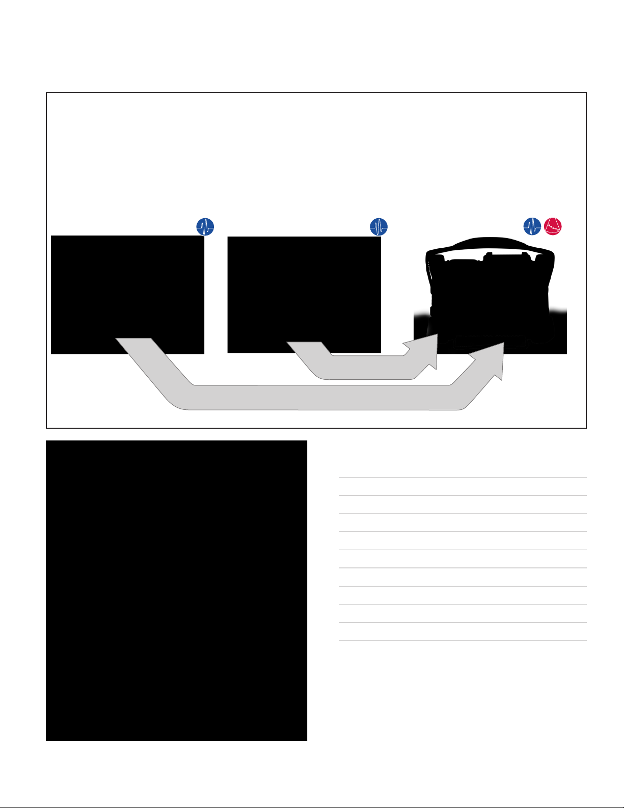
Three Instrument Configuration Levels to Suit Many Inspection Needs
EPOCH 1000
Advanced UT
The EPOCH® 1000 is an advanced
conventional ultrasonic flaw
detector that can be upgraded
with phased array imaging at an
authorized Olympus service center.
EPOCH 1000iR
Advanced UT
+ Phased Array Ready
The EPOCH 1000iR provides
the same ultrasonic flaw detection
capabilities as the EPOCH 1000, with
the benefit of upgrading
to phased array with simple
field‑remote activation.
Field-Remote Upgradable,
Software
Factory Upgradable, Software and Hardware
EPOCH 1000i
Advanced UT
+ Phased Array Built-in
The EPOCH 1000i comes standard
with the same advanced ultrasonic flaw
detection capabilities as the EPOCH
1000, with the addition of a built‑in
phased array imaging package.
Key Industries and Applications
■ General weld inspection
■ Crack detection and sizing
■ Power generation inspections
■ AWS D1.1/D1.5 weld inspection
■ Casting and forging defect inspections
■ DGS/AVG defect sizing
■ In-line inspections
■ Composite delamination and defect inspections
■ Aerospace and maintenance
■ Automotive and transportation
3
Page 4

Advanced Conventional Ultrasound
Upgradeable to Phased Array
The EPOCH® 1000, EPOCH 1000iR, and EPOCH 1000i
provide advanced conventional ultrasound capabilities
for both basic and advanced level users. These portable
instruments can also be integrated into small systems for
high speed scanning and single‑ channel imaging and
come standard with a host of high performance features,
including a 6 kHz maximum Pulse Repetition Frequency
(PRF) with single‑shot measurements for accurate high‑
speed scanning applications, tunable square wave pulser
with PerfectSquare
tal filter sets for exceptional signal‑to‑noise clarity.
Pulser/Receiver Features
• Adjustable pulse repetition frequency (PRF):
5 Hz to 6 kHz.
•
Single‑shot measurements in all standard modes.
• Tunable square wave pulser with PerfectSquare™
technology.
• Programmable analog and alarm outputs.
• Over 30 digital filter sets.
• Digital high dynamic range receiver.
™
technology, and comprehensive digi‑
Standard Software Features
Dynamic DAC/TVG Mode Interface Gate with Gate 1 and Gate 2 Tracking
• Dynamic DAC/TVG – This standard feature enables fast and
dynamic creation of DAC curves using reference reflectors, in
addition to single‑button switching from DAC to TVG mode.
Includes ASME, ASME‑III, JIS, 20% to 80% DAC, Custom, and
TVG Table.
• Onboard DGS/AVG – The DGS/AVG flaw sizing technique
uses calculated attenuation curves to aid you in sizing
potential defects. A vast onboard library of characterized
probes enables you to quickly and easily setup a DGS/AVG
curve and perform precise flaw sizing.
• Interface Gate – This optional third measurement gate enables
real‑time tracking of a variable interface echo in order to
maintain consistent digital measurements.
• AWS Welding Rating – This weld rating calculator provides a
live AWS D1.1/D1.5 code‑compliant “D” value weld rating for
gated flaw indications.
• Floating Gate – This option enables you to “float” Gate 1 and/
or Gate 2 at a selected height compared to a gated echo (–1
dB to –14 dB). This feature provides more consistent, precise
readings, especially in Edge Detection mode.
4
4
www.olympus-ims.com
Page 5

ClearWave™ Conventional Ultrasound Visual Enhancements
SureView Screen
The EPOCH® 1000 series features a new and exciting set of visual
enhancement capabilities to improve the quality and ease of
detection in advanced applications.
• SureView
®
– This feature emulates the functionality of analog
CRT displays, allowing you to visualize peak indications from
reflectors by adding a point of light along the A‑scan trace
where every peak occurs.
• Composite A-scan –
This feature uses every A‑scan acquired
in between screen update rates (multiple A‑scans when
PRF > 60 Hz) to draw a composite A‑scan based on the
maximum envelope of all the acquired A‑scans. This feature
increases confidence of visual detection when scanning
quickly.
• Max Amplitude – This feature displays only the acquired
A‑scan with the highest gated amplitude reading between
screen updates.
Persistence Mode Screen
• Persistence Mode – This feature retains previously acquired
A‑scans on the instrument display for a user‑selectable
duration. This feature provides visual “memory” of an
inspection for enhanced visual detection over a short period
of time.
• Baseline Break
– This feature displays “zero‑cross” points as
lines connecting individual A‑scan lobes to the baseline in full
‑wave rectified mode.
• Min Thickness – This feature displays only the A‑scan
representing the minimum thickness reading between screen
updates.
• Averaged A-scan – This feature enables you to view the
average of the acquired A‑scans. Averaging is applied in
multipliers of 2x, 4x, 8x, 16x, 32x, and 64x.
55
Page 6

Phased Array Imaging Package
with Advanced Conventional Ultrasound
The EPOCH® 1000i provides powerful conven‑
tional ultrasonic and phased array flaw detection
in a portable, rugged instrument. This instrument
offers increased probability of detection of flaws,
better visualization of areas of interest, and im‑
proves inspection efficiency by enabling a single
setup to view A‑scans at multiple angles (focal
laws), thus eliminating the need for multiple
probes and wedges. This instrument provides
the same reliable and exceptional performance
for conventional detection as the EPOCH 1000,
with the added benefit of phased array capabili‑
ties. The EPOCH 1000i allows you to perform
code‑compliant inspections in accordance with
conventional standards, with the advantage of
phased array for increased accuracy and ef‑
ficiency.
Available with a standard 16:16 configura‑
tion and upgradable to 16:64 configuration via
software, the EPOCH 1000i also includes many
sizing features to facilitate in flaw inspections.
The instrument comes standard with A‑scan and
S‑scan reference and sizing cursors for flaw‑size
evaluation.
Gain Calibration Curve
Epoch 1000i Phased Array Specifications
Focal Laws 61
Maximum Elements 64 elements
Maximum Active Aperture 16 elements
Video Filtering Off, Low, High
Display Modes
Image Update Rate
A‑scan, S‑scan, Linear scan, C‑scan, A‑scan plus image
60 Hz update for all A‑scans; 20 Hz update for all images
Combined A-scan and S-scan Views
The EPOCH 1000i features a standard combined A‑scan and
S‑scan view that displays A‑scan data from every angle between
two user‑defined start and end values. Each individual angle, col‑
lectively referred to as focal laws, can be selected to display a live
A‑scan enabling you to detect and characterize potential defects
at multiple angles simultaneously using phased array imaging.
Calibration Across All Focal Laws
When calibrating for gain and zero offset in phased array mode,
the EPOCH 1000i
across all focal laws. These automated calibration procedures
allow you to capture peak amplitude or TOF/distance measure‑
ments from a single reflector across all the imaging angles (focal
laws). The instrument then uses the captured amplitude or TOF/
distance data to adjust the gain and zero offset at each focal law
so that calibrated measurements are provided for every A‑scan.
utilizes single‑step procedures to calibrate
6
6
www.olympus-ims.com
Page 7

Phased Array Features for Manual Imaging Inspections
Phased Array DAC Edit Mode Phased Array DGS/AVG Mode
Standard DAC/TVG for All Focal Laws
The EPOCH 1000i comes standard with DAC/TVG for all focal
laws. This allows you to acquire a DAC curve, or create a TVG
setup from known reflectors for all defined angles/focal laws at
once. The instrument then allows you to edit individual points
acquired during setup for precise DAC or TVG presentation. After
completing the setup, you can use the S‑scan image to detect
potential defects at various focal laws.
Standard Phased Array DGS/AVG
The DGS/AVG flaw sizing technique is included as a standard
option in phased array mode. This feature uses the probe ID and
wedge information to establish the DGS/AVG curve characteris‑
tics, and applies the curve at 0°, 45°, 60°, and 70° focal laws. The
standard EPOCH onboard DGS/AVG menu and modified GAIN
calibration tool allow for quick and easy setup. The option also
provides an interpolated image TVG for easy detection across a
given soundpath range.
77
Page 8

Weld Inspection Solutions with Phased Array
Multi-Angle Phased Array ModePhased Array S-scan with Weld Overlay
Weld Overlay
Weld Overlay is a standard inclusion on the EPOCH 1000i, pro‑
viding a visual reference of a weld profile on the S‑scan display.
This profile enables you to visualize the relative position of indi‑
cations in relation to the weld geometry.
A weld centerline cursor allows manual positioning of the overlay
on the S‑scan. The Weld Overlay enhances your ability to locate,
characterize, and size flaws within the component during inspec‑
tion, and improves reporting.
EPOCH 1000i Multi-Angle
The EPOCH 1000i phased array mode includes a standard feature
called Multi‑Angle. This feature enables you to designate any
three angles, or focal laws, available in the sector scan as “vis‑
ible” focal laws. The A‑scans from each of the three designated
angles are overlaid, one on top of the other in the A‑scan window,
enabling you to view all three A‑scans at the same time. Each
individual angle is color coded for ease of use. This feature is
perfect for inspectors using conventional sizing methods requiring
evaluation at 45°, 60°, and 70°.
True Depth Gates
Measurements gates can be displayed in True Depth mode on the
Sector Scan, thus enabling you to acquire measurements from a
constant depth area throughout the part, regardless of the focal
law selected. This is particularly helpful when using the encoded
C‑scan option, as it enables you to collect information for one
entire skip distance with a single gate position.
The True Depth gates display as horizontal lines on the S‑scan
only; the A‑scan view remains in Soundpath mode.
8
8
AWS “D” Weld Rating displayed for 45° focal lawA-scan and S-scan view with True Depth Gates
AWS Weld Rating
The EPOCH 1000i comes with an AWS D1.1/D1.5 weld rating
calculator. In conjunction with Olympus’ AWS‑rated phased
array transducer, this enables you to use imaging capabilities for
flaw detection while sizing flaws at 45°, 60°, and 70° using the
conventional A‑scan technique, and also view the D value for
onscreen weld rating of any selected A‑scan (focal law).
www.olympus-ims.com
Page 9

Linear Scans and Encoded C-scans
This optional software feature expands the EPOCH 1000i to a
16:64 element configuration and enables linear scans in addition
to encoded or timed C‑scans. Linear scans are collected using a
probe with up to 64 elements, and a maximum active aperture of
16 elements.
C‑scan imaging is created by accumulating image data from the
programmed linear scan or S‑scan across a single‑line scan axis.
An encoder is required to track the position as the probe is moved
along the scan axis. This encoded C‑scan image collects both time
of flight (TOF) and amplitude data from two independent mea‑
surement gates. The live A‑scan is viewable during C‑scan
acquisition. Compressed A‑scan images can be stored for all
points on the C‑scan, and can be reviewed along with the S‑scan
or liner scan from a particular C‑scan location for basic visual
analysis. Data source and type can be adjusted dynamically after
the scan is acquired, and cursors are available for basic scan
sizing. Additional color palettes are available for phased array
image scans. These color palettes provide different color scales for
use with varied applications, and can be modified to meet your
specific needs.
Features
• Encoded or time‑based C‑scan.
• Uni‑ or bi‑directional encoding.
• Supports probes with up to 64 elements.
• Minimum scan resolution of 1 mm (0.040 in.).
•
Compressed A‑scan storage for all C‑scan points.
• C‑scan can be created from S‑scan or linear scan.
• Encoding up to 3 m (118.11 in.) per scan (61 focal laws at
1 mm scan resolution).
•
Image and A‑scan review for visual analysis using cursors.
Zero-degree C-scan
Encoded C-scan Specifications
Maximum File Size 70 Mb
Minimum Scan Resolution 1 mm (0.040 in.)
C-scan Acquisition Rate 20 Hz
Saved A-scan size 500 points
99
Page 10

EPOCH 1000i Phased Array Probes and Accessories
The EPOCH® 1000i supports a new series of phased array probes
to meet the demands of critical inspections. These probes include
specialized probes for specific code compliance, and standard
weld inspection probes, including removable or integral wedge
phased array probes. Most common phased array probes with up
to 64 elements are supported.
Fast Switch from Conventional to Phased Array
The EPOCH 1000i is compatible with all standard single element
transducers in conventional mode. Switching between conven‑
tional UT and phased array inspection is as easy as pressing a
button. The EPOCH 1000i
UT to PA mode, enabling you to easily combine conventional UT
and phased array inspections.
Ordering Information
Numbering systems used to order standard phased array probes.
5L16-9.6x10-A10P-P-2.5-OM
features a high‑speed transition from
Frequency
Array Type
Number of Elements
Active Aperture
Elevation
Frequency
2.25 = 2.25 MHz
5 = 5.0 MHz
10 = 10.0 MHz
Array Type
L = Linear
Number of Elements
16 = 16 Elements
Active Aperture
Active aperture in mm
Elevation
Elevation in mm
Example 10 = 10.0 mm
Probe Type
A = angle beam with external wedge
DGS1 = DGS inspection/Atlas (AVG
probe)
AWS1 = AWS Inspection
Casing Type
Casing type for a given probe type
Connector Type
Cable Length
Cable Type
Casing Type
Probe Type
Cable Type
P = PVC outer
M = Metal armor outer
Cable Length
Cable length in m
2.5 = 2.5 m
5 = 5.0 m
10 = 10.0 m
Connector Type
OM = OmniScan® connector
Probes*
Probe
Description
2.25L8‑A10P U8330663
5L16‑A10P U8330661 5.0 16 0.6 9.6 x 10 10 22.5 (0.89) 15.6 (0.61) 20 (0.79)
10L16‑A10P U8330662 10 16 0.6 9.6 x 10 10 22.5 (0.89) 15.6 (0.61) 20 (0.79)
2.25L16‑AWS1 U8330660
2L8‑DGS1 U8330598
4L16‑DGS1 U8330597 4.0 16 0.5 8 x 9 9 27.3 (1.07) 16.8 (0.66) 22.3 (0.88)
5L64‑A12 U8330593
*All probes are supplied with 2.5-meter cable and OmniScan-style connector. For other variations contact Olympus NDT.
** Represents all 64 elements. Only 16 or fewer elements can be active at one time.
Item
Number
Usage/
Code
Compliance
General
Purpose
AWS D1.1/
D1.5
Integral Wedge/
DGS‑AVG
General
Purpose
Frequency
(MHz)
2.25 8 1.2 9.6 x 10 10 22.5 (0.89) 15.6 (0.61) 20 (0.79)
2.25 16 1.0 16 x 16 16 37.6 (1.48) 25.4 (1.0) 17.8 (0.70)
2.0 8 1.0 8 x 9 9 27.3 (1.07) 16.8 (0.66) 22.3 (0.88)
5.0 64 0.6 38.4 x 10** 10 22.5 (0.89) 44.6 (1.76) 20 (0.79)
Number
of
Elements
Pitch
Active
Aperture
(mm)
Elevation
(mm)
Dimensions in mm
L x W x H (in.)
10
www.olympus-ims.com
Page 11

Mini-Wheel Encoder
The Mini‑Wheel encoder can be used with the encoded C‑scan
option for the positioning and dimensioning of defects in the scan
axis, and can synchronize data acquisition with probe movement.
The Mini‑Wheel encoder is waterproof and can be mounted
onto the Olympus PA wedges using the included bracket kit. This
miniature encoder is made entirely of stainless steel, and features
sealed bearings for long‑lasting smooth operation. The custom
electronic circuit was designed for minimal noise induction.
Features
• Waterproof (designed for IP68 rating).
• Small footprint dimensions.
•
Double O‑ring tire for better adherence.
• Sealed bearing for long‑lasting smooth wheel rotation.
• Strain relief for cable protection.
• Two M3 threaded holes on top of the casing for rigid
attachment.
Standard Inclusions
• 1 Encoder with standard wheel
• 1 Bracket kit
• 1 Allen key screwdriver for bracket attachment
• 1 Carrying case
Ordering Information
The Mini‑Wheel encoder has been designed specifically for use with a variety of instruments. EPOCH 1000i users will require an adaptor
cable to use this encoder.
Cable
Number
CABL‑10016‑0008 U8801209 EPOCH 1000i Mini‑Wheel encoder adaptor cable 0.15
ENC1‑2.5‑DE U8780197 Mini encoder, 2.5m cable, DE15 connector for OmniScan MX 2.5
ENC1‑5‑DE U8780198 Mini encoder, 5.0m cable, DE15 connector for OmniScan MX 5.0
Item
Number
Description
Cable
Length (m)
Wedges for Manual Inspection
Wedge
Number
SA10P‑0L U8720704
SA10P‑N55S U8720705
SAWS1‑0L U8700264 2.25L16‑AWS1 0° LW –30 to 30 Normal 38 (1.49) 37.6 (1.48) 40 (1.57)
SAWS1‑N60S U8720552 2.25L16‑AWS1 55° SW 30 to 70 Normal 45.3 (1.78) 38 (1.49) 30.3 (1.19)
Item
Number
Matching Probe(s)
2.25L8‑A10P, 5L16‑A10P,
10L16‑A10P
2.25L8‑A10P, 5L16‑A10P,
10L16‑A10P
Nominal Refracted
Beam Angle
(in steel)
0° LW –30 to 30 Normal 25.4 (1.0) 23.1 (0.91) 20 (0.79)
55° SW 30 to 70 Normal 23 (0.91) 23.2 (0.91) 14.2 (0.56)
Sweep (°)
Probe
Orientation
Dimensions in mm (in.)
L x W x H
Wedges for Encoded Inspection
The wedges listed below have threaded inserts for connection to encoders. These wedges must be used for encoded inspection setups.
Wedge
Number
SA10‑0L U8720544
SA10‑N55S U8720545
SA12‑0L U8720549 5L64‑A12 0° LW –30 to 30 Normal
SA12‑N55S U8720550 5L64‑A12 55° SW 30 to 70 Normal
Item
Number
Matching
Probe(s)
2.25L8‑A10P, 5L16‑A10P,
10L16‑A10P
2.25L8‑A10P, 5L16‑A10P,
10L16‑A10P
Nominal
Refracted
Beam Angle
0° LW –30 to 30 Normal
55° SW 30 to 70 Normal
Sweep (°)
Orientation
Probe
Dimensions in mm (in.)
L x W x H
25.4
(1.0)
23
(0.91)
61.8
(2.43)
58
(2.28)
23
(0.91)
23
(0.91)
23
(0.91)
23
(0.91)
20
(0.79)
14.2
(0.56)
53.4
(2.1)
23
(0.91)
Removable
IHC Ring
SA10‑IHC
SA10‑IHC
SA12‑IHC
SA12‑IHC
11
Page 12

Onboard Media and Report Generation
The EPOCH 1000 series is equipped with onboard capabilities for
file and database transfers, image capture, and basic reporting.
These features provide you with multiple options for accessing
previously stored data, in addition to live images.
Two forms of removable media, compact flash (CF) cards and
USB memory sticks, can be used to export of images and reports.
A compact flash (CF) card is included with every EPOCH 1000
series instrument.
Instrument Data Logger
The sophisticated data logger is designed for easy data capture for
image reporting, measurements, and calibration information. The
data logger features dedicated calibration files with quick recall
capability for fast setup adjustment, in addition to inspections files
with either full data or basic image and measurement captures for
quick reporting purposes. Advanced file types are also available
for a variety of corrosion applications.
File and Database Transfers
The complete instrument database can be backed up to a USB
memory stick and restored onto any EPOCH 1000 series unit.
Individual files can also be copied to a USB memory stick for
transfer between units.
Image Capture
Screen shots of the live instrument screen can be captured and ex‑
ported using either removable media format (CF or USB). Specific
file types can also be created to allow for easy export of the saved
file image for use in any kind of report.
Reporting Capabilities
The enhanced reporting capabilities of the EPOCH 1000 series
enable dynamic output of information in a variety of formats.
Reports from stored data files can be created onboard the instru‑
ment and sent to the desired media destination (CF or USB) in
HTML format. Two report options are available based on the
specific information required for the report. A custom logo can be
imported and used in place of the standard Olympus logo in the
report header.
Specifications
Format HTML
Type Summary (measurement data only)
Header Logo Customizable (bmp, jpg, png formats)
Data (complete setup and waveform)
12
www.olympus-ims.com
Page 13

PC Data Management and Reporting
GageView® Pro Data Software
The EPOCH 1000 series is fully compatible with GageView Pro
Olympus’ standard portable instrument PC interface program.
The GageView Pro interface program can be used to download
saved data for review, export, and backup, and to generate reports
containing setup parameters, measurement data, and waveforms.
Database backup files can be viewed directly in GageView Pro
using a USB memory stick without having to connect the EPOCH
1000 series instrument to the PC. This feature allows for backup,
data review, and report generation of instrument files without
having to remove the instrument from in‑field work. Other tools,
including an instrument firmware upgrade utility, are also available
as part of this program.
Features
• Download saved inspection data and setup files.
• Review setup information and measurements on a PC.
• Export measurements and calibration data to common
spreadsheet programs.
• Back up calibration and inspection data from the instrument
• Upgrade instrument firmware.
• Generate reports with setup parameters, measurements, and
waveforms.
• Access saved data through unit database backup files.
Accessories
The EPOCH 1000 series offers various optional accessories to al‑
low full functionality of available features.
EPXT-C-VGA-6 (U8779019): VGA output cable
EP4P/C-USB-6 (U8840084): USB client cable
EP1000-C-RS232-6 (U8779197):
EP1000-C-26OUT-6 (U8779018): Hardware I/O cable
(alarm outputs triggering)
EP1000-C-9OUT-6 (U8779017): Hardware I/O cable
(analog output)
EP4/CH (U8140055): Chest harness
EPXT-EC-X: External battery charger
EPXT-BAT-L (U8760021):
EP1000-TC-S (U8764078): Small Transport Case
EP1000-TC-L (U864079): Large Transport Case
Extra battery (lithium‑ion)
RS‑232 communications cable
Small Transport Case (P/N: EP1000-TC-S)
Large Transport Case (P/N: EP1000-TC-L)
13
Page 14

Rugged. Portable. Meets the Demands of the Toughest
Inspection Environments.
The EPOCH® 1000 series is designed to meet the IP66 environ‑
mental rating. Tested for shock, vibration, explosive atmosphere,
and wide temperature range, these instruments can withstand op‑
eration in harsh inspection conditions. Some of the EPOCH 1000
series’ other key physical features include:
• Large, full VGA (640x480) resolution color transflective display
for optimum viewing in low or bright lighting conditions.
• Rugged rubber handle for easy transport.
•
Durable instrument‑mounted D‑rings for chest harness use.
• Front and rear stands for table‑top or steep inclined viewing.
• USB Client and Host ports for PC communication, direct
printing and communication with peripheral devices.
• VGA output for presentations, training, and remote instrument
monitoring.
•
Programmable analog outputs, alarm outputs, and RS‑232
communication.
•
Standard internal, rechargeable lithium‑ion battery.
General Specifications
Overall Dimensions (W x H x D) 252 mm x 177 mm x 107 mm (9.92 in. x 6.97 in. x 4.2 in.)
Weight
Keypad English, International, Japanese, Chinese
Languages English, Spanish, French, German, Japanese, Chinese, Russian, Italian, Polish
Transducer Connections BNC or Number 1 LEMO
Data Storage Onboard up to 10,000 IDs with waveform, standard 4 GB compact flash card (removable)
Battery Type
Battery Life 8 hours (conventional UT mode); 7 hours (phased array mode)
Power Requirements AC Mains: 100 VAC to 120 VAC, 200 VAC to 240 VAC, 50 Hz to 60 Hz
Standby Mode Adjustable from 15 minutes to 120 minutes with 50% less battery consumption.
Display Type Full VGA (640 x 480 pixels) Transflective Color LCD, 60 Hz update rate
Display Dimensions (W x H, Diag.) 132.5 mm x 99.4 mm, 165.1 mm (5.2 in. x 3.9 in., 6.5 in.)
Inputs/Outputs
USB Ports 1 USB Client, 3 USB Host ports
RS‑232 Yes
Video Output VGA output standard
Analog Output 4 analog outputs, Selectable 1V/10V Full Scale, 4 mA max
Alarm Output 6 alarm outputs, 5V TTL, 10 mA
Trigger I/O Trigger input 5V TTL; trigger output, 5 V TTL, 10 mA
Encoder Inputs
Environmental Ratings
IP Rating Designed to meet requirements of IP66
Explosive Atmosphere
Shock Tested
Vibration Tested Sine vibration, IEC 60068‑2‑6, 5 Hz to 150 Hz @ 0.03 in. or 2 g’s Displacement Amplitude, 20 sweep cycles
Operating Temperature –10 °C to 50 °C (–14 °F to 122 °F)
Battery Storage Temperature –20 °C to 60 °C (–4 °F to 140 °F)
Battery Recharge Temperature 0 °C to 40 °C (32 °F to 104 °F)
3.67 kg (8.1 lb), including lithium‑ion battery
Single lithium‑ion rechargeable standard
2‑axis encoder line (quadrature)
Tested to MIL‑STD‑810F, Method 511.4, Procedure 1. Atmosphere defined per NFPA 70, Article 500 as Class I, Division
2, Group D.
IEC 600689‑2‑27, 60 g’s, 6 µsec Half‑Sine, 18 Axes total
14
www.olympus-ims.com
Page 15

EPOCH 1000 Series Conventional/Phased Array Specifications*
EPOCH® 1000, EPOCH 1000iR, EPOCH 1000i
(conventional UT mode)
Pulser
Pulser Type Tunable Square Wave
PRF 5 Hz to 6,000 Hz in 5 Hz increments Manually adjustable. Maximum 1,520 Hz
Energy Settings 50 V to 475 V in 25 V increments 40 V or 80 V
Pulse Width
Damping 50 Ω, 100 Ω, 200 Ω, 400 Ω Not applicable
Pulser Delay Not applicable 0 to 10 µs, 2.5 ns resolution
Receiver
Gain 0 to 110 dB 0 to 80 dB
Maximum Input Signal
Receiver Input Imped‑
ance
Receiver Bandwidth 0.2 MHz to 26.5 MHz @ –3 dB 0.5 MHz to 12.5 MHz @ –3 dB
Receiver Delay NA 0 µs to 10 µs, 2.5 ns resolution
Digital Filter Settings
Rectification Full wave, positive half wave, negative half wave, RF
Reject 0 to 80% FSH with visual warning
Amplitude Measurement
Measurement Rate Equivalent to PRF in all modes
Calibration
Automated Calibration
Test Modes Pulse Echo, Dual, or Through Transmission Pulse Echo
Units Millimeters, inches, or microseconds
Range
Velocity 635 to 15, 240 m/s (0.0250 to 0.6000 in./µs)
ZeroOffset 0 µs to 750 µs Not applicable
Display Delay –59 mm to 25,400 mm (–2.323 in. to 1000 in.) 0 to max range
Refracted Angle 0° to 85° in 0.1° increments
Gates
Measurement Gates
Measurement Mode Soundpath Soundpath, Depth
Interface Gate Optional, with Gate 1 and Gate 2 tracking Not applicable
Gate Start Variable over entire displayed range
Gate Width Variable from gate start to end of displayed range
Gate Height
Alarms
Reference Cursors Two reference cursors for A‑scans
Measurements
Displayed Measurement Six locations available (manual or auto selection)
Gate 1
Gate 2 Same as Gate 1
IF Gate (optional) Thickness Not applicable
Echo‑to‑Echo Standard. Choose between Gate2‑1, Gate2‑IF, and Gate1‑IF Standard
Other Measurements Overshoot (dB) value for DGS/AVG, ERS (equivalent reflector size) for DGS/AVG, AWS D1.1/D1.5 rating (D), reject value
DAC/TVG Standard
DAC Points Up to 50 points, 110 dB dynamic range Up to 20 points, 40 dB dynamic
Special DAC Modes 20% to 80% DAC, Custom DAC (up to 6 curves) Not applicable
TVG Table
Curved Surface Correction Standard. Tube or bar OD correction for angle beam measurements
Adjustable from 25 ns to 5,000 ns (0.1 MHz) with Per‑
fectSquare
20 Vp‑p 250 mVp‑p per channel
400 Ω ± 5% 50 Ω ± 10%
Standard filter set (EN12668‑1 Test & Compliant): 7 filters
Advanced filter set (not tested to EN12668‑1): 30 filters
0% to 110% full‑screen height with 0.25% resolution
•Velocity,ZeroOffset
•StraightBeam(rstbackwallorecho-to-echo)
•AngleBeam(SoundpathorDepth)
3.60 mm to 26,808 mm (0.143 in. to 1055 in.)
Longitudinal velocity in steel
Two fully independent gates for amplitude and time‑of‑flight measurements
Variable from 2% to 95% full‑screen height
•Positiveandnegativethreshold
•Minimumdepth
Thickness, soundpath, projection, depth, amplitude, time‑of‑flight, min./max. depth, min./max. amplitude
Up to 50 points, 110 dB dynamic range, compatible with IF
Gate at all PRF settings
™
Technology
EPOCH 1000i
(PA mode)
Adjustable from 40 ns to 1,000 ns with PerfectSquare™ Technol‑
ogy
6 filters
•Velocity,ZeroOffset,Sensitivity
•SoundpathorDepth(ZeroOffset)
31 focal laws, 2.58 mm to 37.5 mm (0.101 in. to 14.76 in.)
Longitudinal velocity in steel
61 angular focal laws, 0.5°, 1.0, 1.5°, or 2.0° increments
Adjustable from –80° to +80°
•Positiveandnegativethreshold(forselectedfocallaw)
•Minimumdepth(forselectedfocallaw)
Two reference cursors for A‑scans; four reference cursors for im‑
ages
Up to 20 points, 40 dB dynamic
15
Page 16

The EPOCH® Flaw Detector Family: The EPOCH flaw detector
line features vertical and horizontal layout instruments that span
the range of inspection capabilities from basic to advanced.
The EPOCH 600 and EPOCH 1000 series flaw detectors feature
horizontal layout instruments for enlarged A‑scan and image
representation in a portable format, and provide an exceptionally
high quality of digital flaw detection technology.
www.olympus-ims.com
info@olympusNDT.com
48 Woerd Avenue, Waltham, MA 02453, USA, Tel.: (1) 781-419-3900
12569 Gulf Freeway, Houston, TX 77034, USA, Tel.: (1) 281-922-9300
505, boul. du Parc-Technologique, Québec (Québec) G1P 4S9, Tel.: (1) 418-872-1155
1109 78 Ave, Edmonton (Alberta) T6P 1L8
Epoch1000_EN_201109• Printed in the USA • Copyright © 2010 by Olympus NDT.
*All specications are subject to change without notice.
All brands are trademarks or registered trademarks of their respective owners and third party entities.
is ISO 9001 and 14001 certified.
 Loading...