

Page 1
Model 2680M1-M7
Variable
Gain
Amplifier
Optional
2 Pole
Butterworth
Low Pass
Filter
Charge
Convertor
Regulator
A+28 VDC
B
C
Unbiased
Output
Biased
Output
Signal &
Power
Ground
D
E
Case GND
Viking
VR5/4AG15
10-32 THD
Input
Connector
GAIN ADJUST
.154 (3.91) DIA 2 PL
.755 (19.18)
.745 (18.92)
1.000
(25.40)
.060
(1.52)
COUNTERBORED FOR
#6 CAP SCREW
.750
(19.05)
OUTPUT (VIKING
#VR5/4AG15 OR
EQUIVALENT)
PIN FUNCTIONS
A - +28 V DC
B - UNBIASED OUTPUT
C - BIASED OUTPUT
D - SIG & PWR GND
E - CASE GND
INPUT (MICRODOT #51-49 OR
EQUIVALENT) 10-32 UNF-2A THD
.200
(5.08)
.120
(3.05)
1.500
(38.10)
.120
(3.05)
1.000
(25.40)
1.255 (31.75)
1.245 (31.62)
D
C
B
A
E
STANDARD TOLERANCE
INCHES (MILLIMETERS)
.XX = +/- .02 (.X = +/- .5)
.XXX = +/- .010 (.XX = +/- .25)
Airborne charge amplifiers
Features Description
• For use with piezoelectric transducers
• Small, rugged, light weight
• Dual outputs, biased and unbiased
• Adjustable gain
• Optional low pass filter
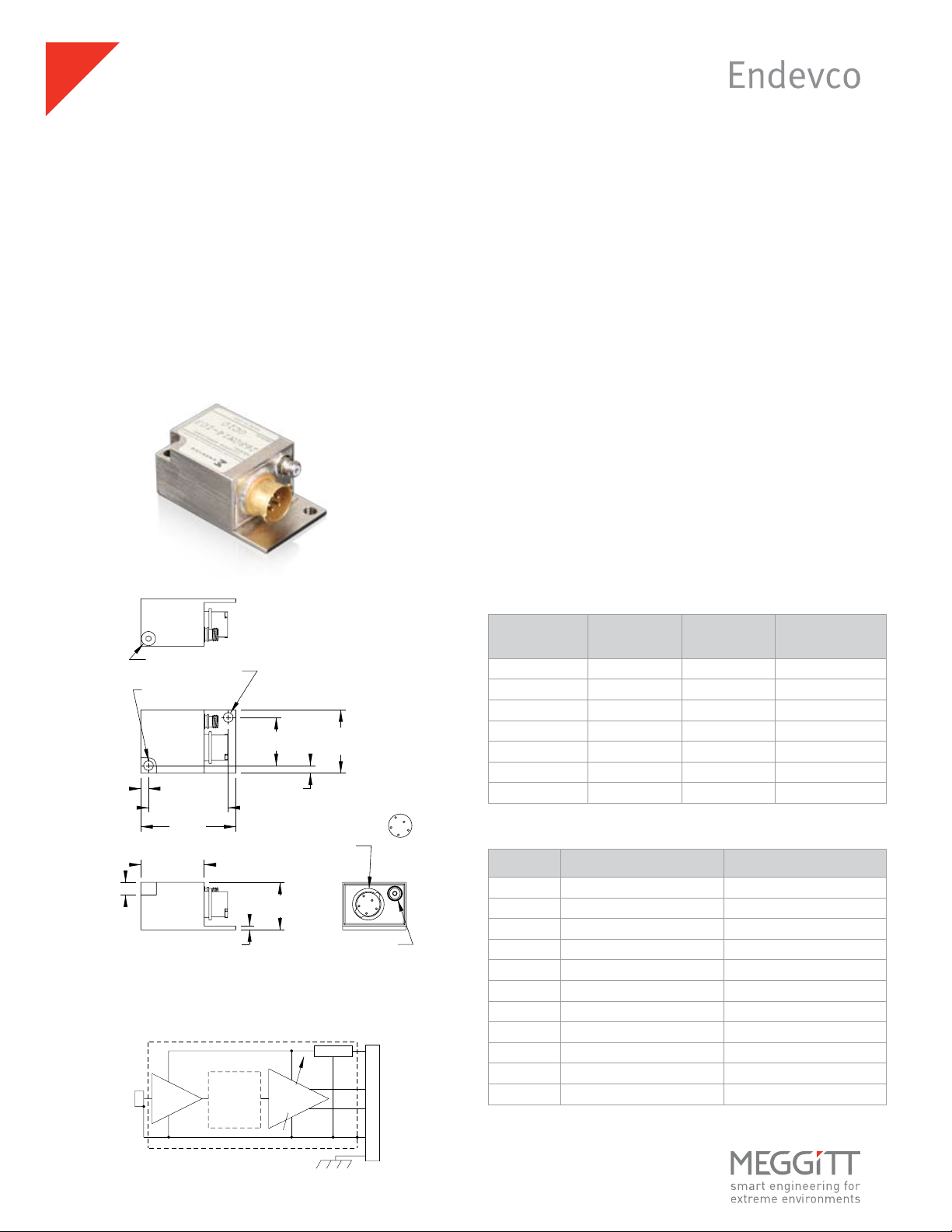
The Endevco models 2680M1-XXX through 2680M7-XXX Charge
Amplifiers are designed for use with piezoelectric transducers
and are suitable for airborne applications. Hybrid microcircuit
construction results in small size, ruggedness and low power
consumption. The airborne charge amplifiers have an output
voltage proportional to the input charge. As a result, the amplifier sensitivity is not appreciably affected by the capacitance of
the input cable.
The use of modular construction techniques permits great
versatility in gain and filter choices. This unit has two outputs, a
biased output and an unbiased output. Both outputs are adjustable with a common gain control. The M1 through M7 defines
the charge gain per Table 1.
The -XXX describes the upper cutoff frequency (-5% point) per
Table 2. For example, a -101 has a low pass filter which is flat up
to 100 Hz, a -502 has a low pass filter which is flat up to 5000 Hz.
"M" number Gain range Input pulse Residual noise
[mV/pC] [pC] [mV rms]
M1 0.1 to 1.0 50 000 1.5
M2 0.2 to 2.0 25 000 1.5
M3 0.5 to 5.0 10 000 1.5
M4 1.0 to 10.0 5000 1.5
M5 2.0 to 20.0 2500 1.5
M6 5.0 to 50.0 1000 1.5
M7 10.0 to 100 500 2.0
Table 1: Gain ranges
Dash No. Lower cutoff freq. [-5%] Upper cutoff freq. [-5%]
None 5 Hz 20 kHz (10 kHz for M7)
101 5 Hz 100 Hz
201 5 Hz 200 Hz
501 5 Hz 500 Hz
102 5 Hz 1 kHz
202 5 Hz 2 kHz
502 5 Hz 5 kHz
103 5 Hz 10 kHz
203 5 Hz 20 kHz (10 kHz for M7)
402 5 Hz 4 kHz
250 5 Hz 25 Hz
Table 2: Frequency response
Page 2
APPLIES TO CALIFORNIA FACILITY
Model 2680M1-M7
Airborne charge amplifiers
Specifications
The following performance specifications conform to ISA-RP-37.2 (1964) and are typical values, referenced at +75˚F (+24˚C) and 100 Hz,
unless otherwise noted. Calibration data, traceable to National Institute of Standards and Technology (NIST), is supplied.
Inputs
Type Piezoelectric single-ended with one side connected to signal ground
Source resistance 25 MΩ minimum
Source capacitance 10 000 pF max
Overload recovery A half sine pulse of 1ms duration and with an amplitude as specified in Table 1 (or less) will cause no
spurious effects at the amplifier output other than clipping.
Outputs
Type Both biased and unbiased outputs are single-ended with one side connected to circuit ground.
Load impedance The parallel combination of both outputs load resistors shall be 10 kΩ or greater to meet all specifications.
Output impedance Biased output 50 Ω max, direct coupled
Unbiased output 50 Ω max, in series with at least 16 μF
DC output bias voltage Biased output 2.50 V ±3% with load resistances of 10 kΩ minimum
Unbiased output 0.00 V +0.050 V / -0.00 V
Linear output voltage Biased output 4.65 V pk-pk minimum with 10 kΩ load
Unbiased output 4.65 V pk-pk minimum with 1 MΩ load
4.25 V pk-pk minimum with 10 kΩ load
Limited output voltage (biased output) 0.00 V +0.075/-0.000 V and 5.30 V +0.00/-0.30 V
Limited output current (both output) 0.465 mA pk-pk minimum with 10 kΩ load
Transfer characteristics
Gain range Adjustable as specified in Table 1
Gain stability 0.05% maximum change per 1000 pF change in source capacitance at the input
Gain stability with supply voltage 0.25% maximum with changes in supply voltage over the specified limits
Frequency response The gain at the upper and lower cutoff frequencies is 5% lower than the gain at 20 Hz. See Table 2.
Amplitude linearity ±0.5% of reading from best fit straight line approximation
Residual noise 0.01 pC rms + 0.01 pC rms per 1000 pF RTI or noise RTO as specified in Table 1 whichever is greater,
when measured over a bandwidth of 3 Hz to 20 kHz
Shock and vibration sensitivity 0.01 pC/g maximum RTI
Environmental
Temperature Operating -67°F to 212°F (-55°C to 100°C)
Storage -99°F to 257°F (-73°C to 125°C)
Humidity 100% R.H. when sealing screw is soldered. Meets MIL-STD-810D, Method 507.2, Procedure III
Altitude No effect when sealing screw is soldered.
Vibration 120 mils D.A. 5 Hz to 55 Hz
20 g 55 Hz to 2000 Hz
Shock 100 g 6.5 millisecond sawtooth
EMC capability The unit meets the requirements of the following specifications:
MIL-STD-826, CLASS Am; MIL-I-6181D; MSFC-SPEC-279, CLASS 1; AF/BSD EXHIBIT 62-87
Power
Voltage 20 to 32 VDC (28 VDC nominal)
Current 20 mA maximum for unfiltered units, 25 mA maximum for filtered units
Polarity protection Not damaged by a polarity reversal of the 28 V supply
Case isolation Case and signal grounds isolated from each other by 50 M½ or greater at 50 VDC
Physical characteristics
Dimensions 1.00” l x 1.00” w x 0.75” h (25.4 mm x 25.4 mm x 19.1 mm) exclusive of mounting flange and connectors
Mounting Unit mounts with two 6-32 screws
Case material Aluminum with electroless nickel plate finish
Weight 1.2 oz (34 gm) maximum
Connectors Input 10-32 coaxial
Output Viking VR5/4AG15. Pin A is the 28 VDC, Pin B unbiased output, Pin C biased output,
Pin D power and signal ground, Pin E case ground
Accessories
Instruction manual
21997 Accessory Kit includes:
EP38 Mating plug Viking #VP5/4CE6
EP35 Hood Viking #VS4/16C5
EP31 Potting sleeve Viking #VS4/16C9
Continued product improvement necessitates that Endevco reserve the right to modify these specifications without notice. Endevco maintains a program of constant surveillance
over all products to ensure a high level of reliability. This program includes attention to reliability factors during product design, the support of stringent Quality Control
requirements, and compulsory corrective action procedures. These measures, together with conservative specifications have made the name Endevco synonymous with reliability.
©ENDEVCO CORPORATION. ALL RIGHTS RESERVED 30700 RANCHO VIEJO ROAD, SAN JUAN CAPISTRANO, CA92675 USA
(800) 982-6732 • (949) 493-8181 fax (949) 661-7231 • www.endevco.com • Email: applications@endevco.com 111909
 Loading...