

Page 1
RF Safety
Test Solutions
Electric and Magnetic Field Measurement
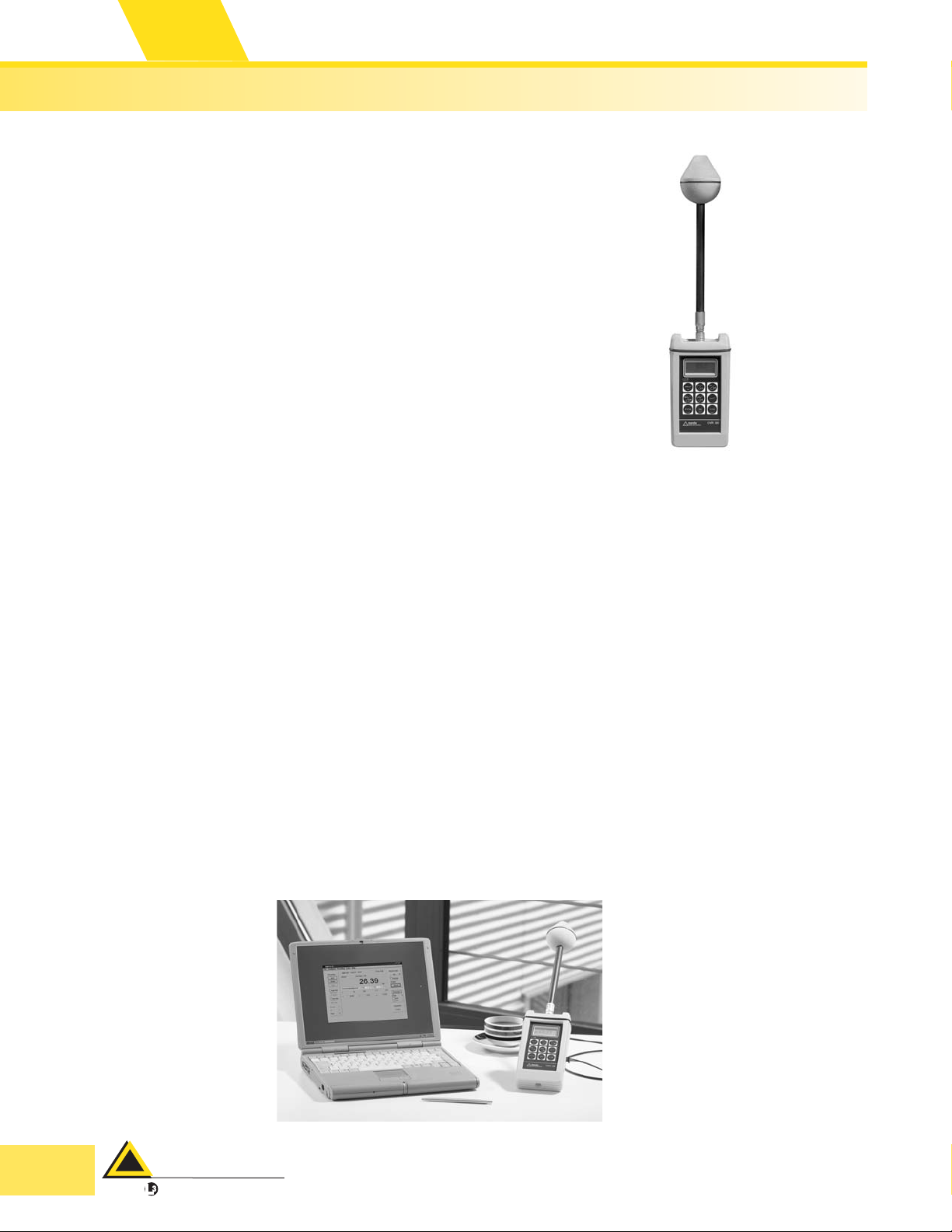
EMR-300 Broadband
RF Survey Meter
Available with Isotropic Probes to cover
◆
3 kHz to 60 GHz
Easy-to-Use Design
◆
Lightweight and Rugged
◆
Cost Effective
◆
Fully Automatic Zeroing
◆
24 Month Calibration Interval
◆
Description
The EMR-300 Meter features a lightweight design with an
integral shock resistant cover. Customers utilize this
meter for high sensitivity andhighdynamic range surveys.
Electric, Magnetic and shaped probes are available to satisfy virtually every survey need. Every probe available has
approximately 60dB of dynamic range, without changing
measurement ranges. Unique to this series are H-field
probes available from 3 kHz to 1 GHz.
All other specifications are the same. This lightweight meter provides simple operation. All probes are automatically detected at turn-on, and automatically “zeroed”,
even while immersed in an RF field. At six-minute intervals,
this meter re-zeroes itself without operator intervention.
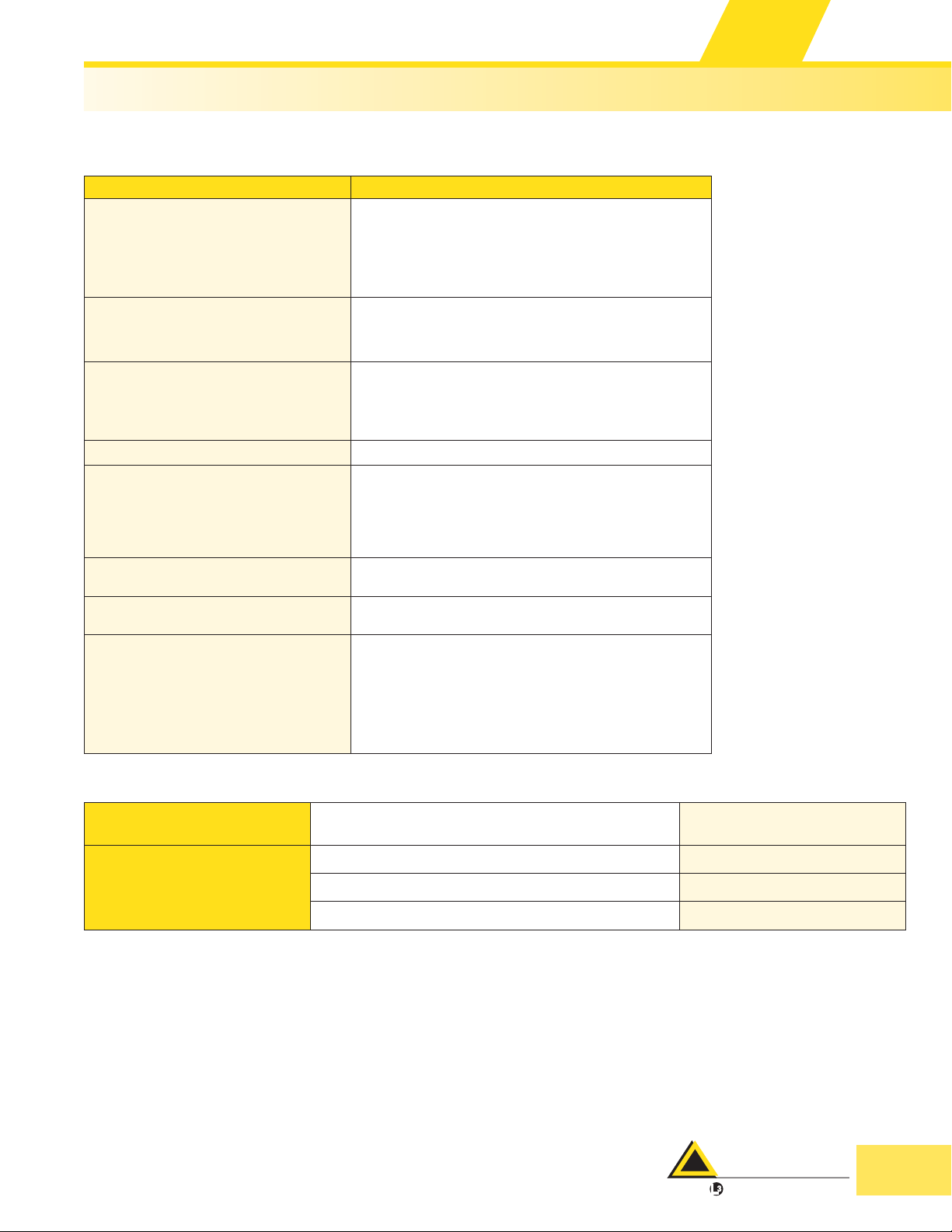
The EMR-300 is supplied with the EMR-TS software and
data transfer package. This includes 2meter and 20 meter
fiber optic cables that allow bi-directional communication
from your computer to the EMR meter.
The EMR-300 has the ability to store readings and also
has time and spatial averaging capabilities. Spatially aver
aged limits are the basis for almost all international stan
dards or guidance’s. For readings of averaged fields such
as vertical scans over the height of the body, or time
averaged readings in front of a rotating radar, averaging is
almost always required to properly assess the whole body
limits.
Data logging is an additional feature of the EMR-300. Being able to store readings can be a time saving, important
method of documenting your survey. Data is stored with
time-of-day information so that you can tie readings directly to the date and time of your survey.
The probes compatible with the EMR-300 are available as
calibrated (“C”) or non-calibrated versions. See pages
48-51 for more details.
The EMR-300 is supplied with a case that holds the meter,
manual, charger and multiple probes (available probes
are listed on pages 48-51). The EMR-TS software and ca
ble system is also supplied as standard, which consists of
the software, 2 and 20 meter fiber optic cables and an
adapter to convert the fiber optic signals to a common
9-pin serial connector. All EMR meters and probes have a
two-year warranty and calibration interval.
50 Years of
Excellence
-
narda
Safety Test Solutions
communications company
an
USA TEL: (1) 631 231-1700 • FAX: (1) 631 231-1711 • E-MAIL: NardaSTS@L-3COM.com • www.narda-sts.com
GERMANY TEL: 49-7121-9732-777 • FAX: 49-7121-9732-790 • E-MAIL: support@narda-sts.de • www.narda-sts.de
Page 2
RF Safety
Test Solutions
50 Years of
Excellence
Electric and Magnetic Field Measurement
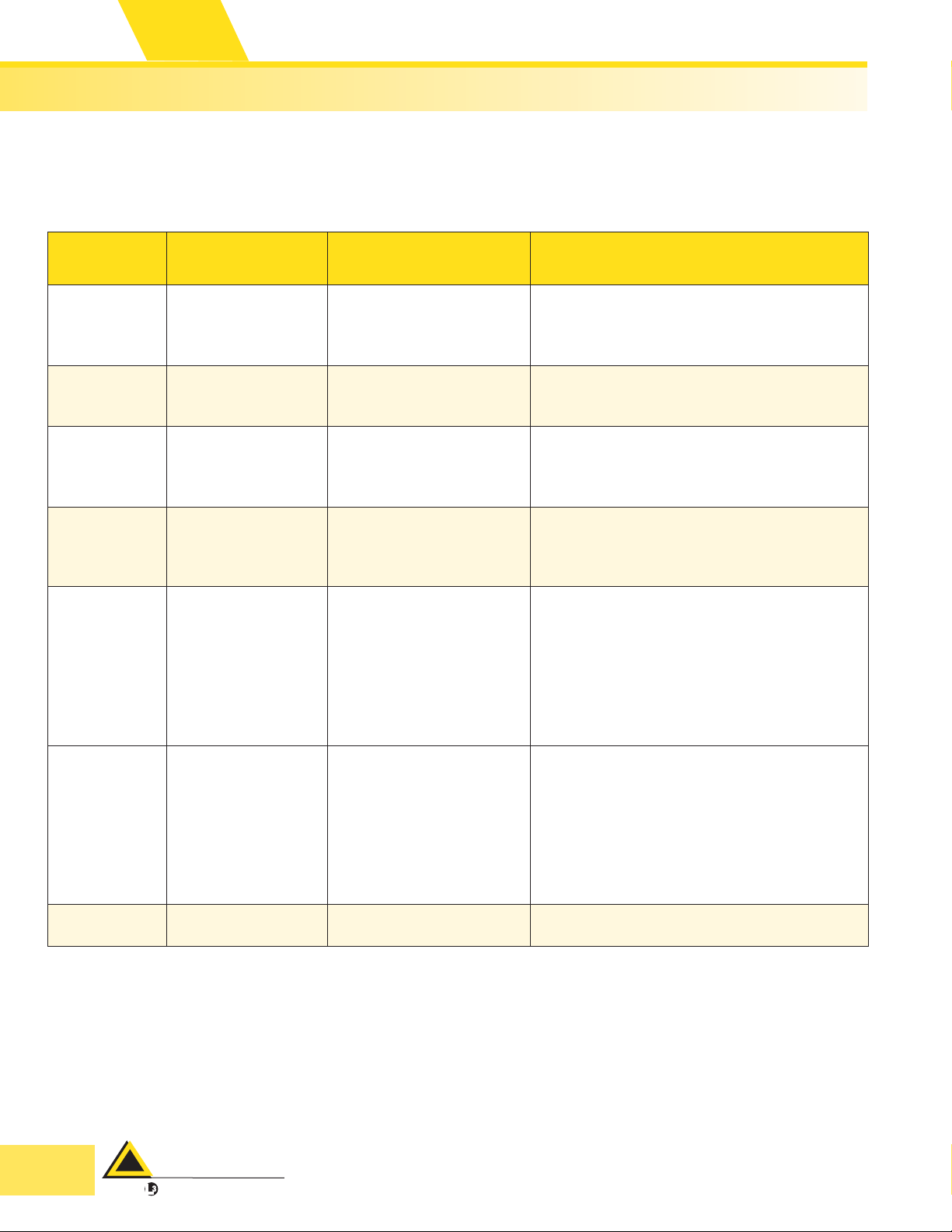
Specifications
Specifications EMR-300
Display Specification
Display Type
Display Refresh Rate
Resolution
Settling Time (Typical)
Warning Circuits
Visible
Audible
Measurement Functions
Units
Results Displayed
Averaging
Calibration Data One calibration factor settable per probe
Self Tests
Interfaces
Additional Functions
General Specifications
Power Supply
Operating Time
Operating Temperature Range
Size (HxWxD)
Weight
4 ½ Digit LCD
400 msec., typical
0.01 V/m, 0.0001 A/m
1 sec. (0 to 90% of measured value)
Red LED’s in the keypad
ON/OFF and variable threshold
Piezoelectric, tone varies with measured value
2
V/m, A/m, mW/cm
Current result or maximum value since turn-on
Current result or variable from 4 sec. to 15 min.
Automatic self-test of A/D converter, battery,
supply voltages, memory and zero adjustment.
Periodic zero adjustment and battery check
during operation
All tests can be performed during exposure to the field.
Fiber optic, serial interface for results transfer, remote
control and calibration. V.24 (RS-232)
Storage of up to 1500 values, real-time clock and spatial
averaging (over time or over measurement points)
2 ea. AA type, re-chargeable batteries
8 hours (typical), re-charged via supplied charger
0 to +50°C
18.3" x 3.78" x 2.52" (465 x 96 x 64 mm)
450 grams (approx.)
, W/m2, % of limit value
Ordering Information
EMR-300 Meter
Optional Accessories
USA TEL: (1) 631 231-1700 • FAX: (1) 631 231-1711 • E-MAIL: NardaSTS@L-3COM.com • www.narda-sts.com
GERMANY TEL: 49-7121-9732-777 • FAX: 49-7121-9732-790 • E-MAIL: support@narda-sts.de • www.narda-sts.de
Supplied with non-metallic support, EMR-TS PC transfer set,
carrying case, batteries, charger and manuals
Non-metallic Tripod 2244/90.31
Probe Cable, 1.2 meter 2244/90.35
27 MHz, Test Generator 2244/90.38
2244/31
narda
Safety Test Solutions
communications company
an
Page 3
RF Safety
Test Solutions
Electric and Magnetic Field Measurement
EMR-300 Probes
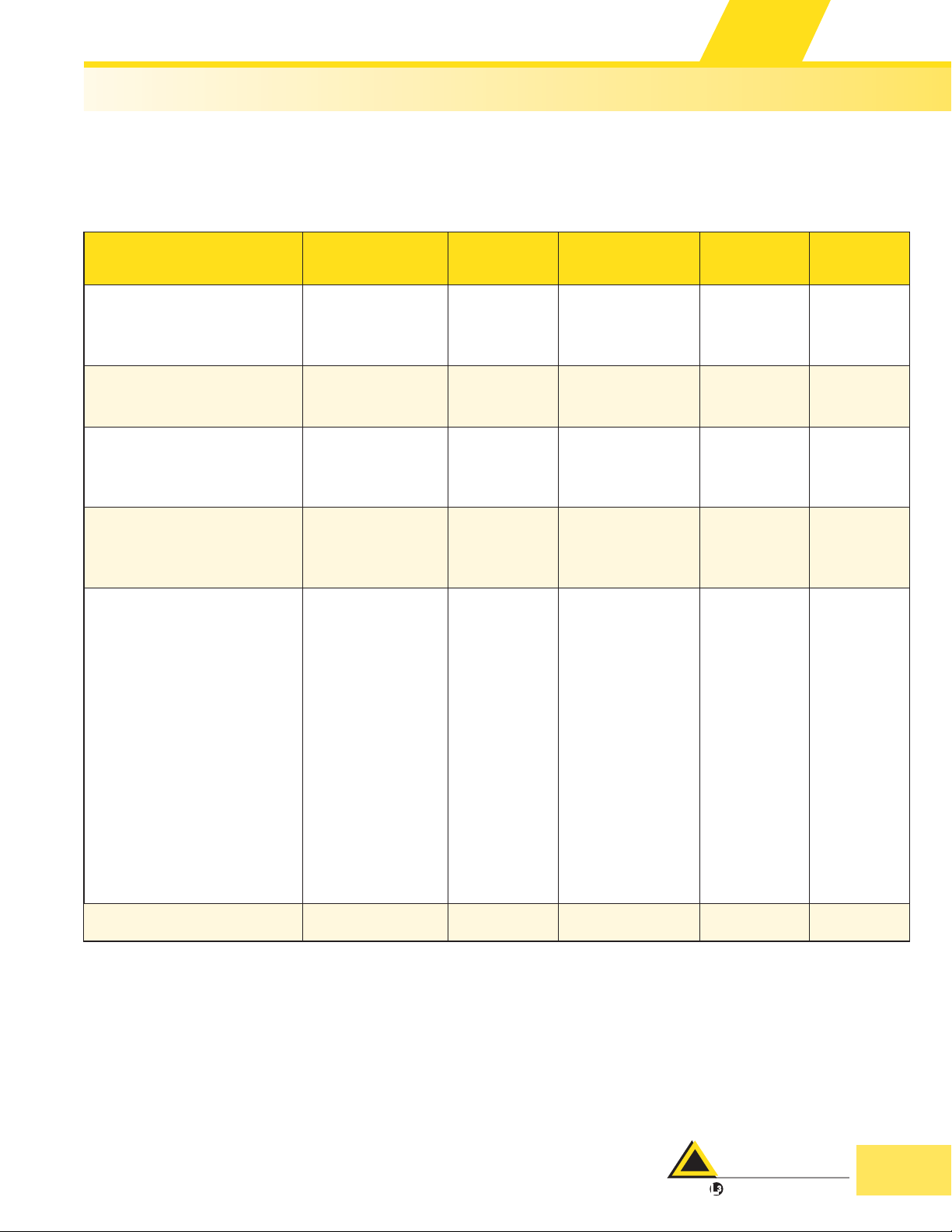
Electric Field
Probe Model Frequency Range Measurement Range Frequency Sensitivity
Type 8C
2244/90.21
Type 18C
2244/90.73
Type 9C
2244/90.23
Type 11C
2244/90.25
Type 25C
2244/90.59
Type 26C
2244/90.61
Type 33C
2244/90.81
100 kHz to 3 GHz 0.6 to 800 V/m
100 kHz to 3 GHz 0.2 to 320 V/m
3 MHz to 18 GHz 0.8 to 1000 V/m
27 MHz to 60 GHz 0.7 to 300 V/m
300 kHz to 40 GHz 0.3 to 600% of Standard
300 kHz to 40 GHz 0.3 to 600% of Standard
300 MHz to 50 GHz 8.0 to 614 V/m ±1.25 dB (1.8 to 40 GHz)
b
b
±0.5 dB (100 kHz to 100 MHz)
± 1.4 dB (100 MHz to 3 GHz)
± 1.2 dB (300 kHz to 1.2 GHz)
±1.5 dB (1.2 to 2.5 GHz)
-3dB (at 3 GHz)
±1.5 dB (10 to 100 MHz)
± 2.4 dB (100 MHz to 8 GHz)
±3.0 dB (8.0 to 18 GHz)
±0.5dB (27 to 150 MHz)
± 0.8dB (150 MHz to 1 GHz)
± 0.5 dB (1 to 40 GHz)
±1dB (40 to 60 GHz
±1.0 dB (300 kHz to 1 MHz)
± 1.0 dB (1 to 200 MHz)
±1.2 dB (200 MHz to 1 GHz)
±1.5 dB (1 to 2 GHz)
± 2.0 dB (2 to 4 GHz)
+4/-3 dB (4 to 18 GHz)
+5/-2 dB (18 to 36 GHz)
+0/-6 dB (36 to 40 GHz)
±6.0 dB (300 kHz to 1 MHz)
±1.0 dB (1 to 200 MHz)
±1.2 dB (200 MHz to 1 GHz)
±1.5 dB (1 to 2 GHz)
±2.0 dB (2 to 4 GHz)
+4/-3 dB (4 to 18 GHz)
+5/-2 dB (18 to 36 GHz)
+0/-6 dB (36 to 40 GHz)
50 Years of
Excellence
a
a
)
narda
communications company
an
USA TEL: (1) 631 231-1700 • FAX: (1) 631 231-1711 • E-MAIL: NardaSTS@L-3COM.com • www.narda-sts.com
GERMANY TEL: 49-7121-9732-777 • FAX: 49-7121-9732-790 • E-MAIL: support@narda-sts.de • www.narda-sts.de
33
Page 4
RF Safety
Test Solutions
50 Years of
Excellence
Linearity
±3 dB (0.6 to 1.25 V/m)
±1.0 dB (1.25 to 2.5 V/m)
±0.5 dB (2.5 to 400 V/m)
±0.7 dB (400 to 800 V/m)
±0.5 dB (1.2 to 200 V/m)
±0.7 dB (200 to 320 V/m)
±3dB (0.8 to 1.65 V/m)
±1.0 dB (1.65 to 3.3 V/m)
±0.5 dB (3.3 to 300 V/m)
±8 dB (300 to 1000 V/m)
Electric and Magnetic Field Measurement
c
Isotropic
Deviation
d
±1.0 dB for
f>1MHz
Overload
Limit
700 mW/cm
70 W/cm
>45 dB (300 kHz)
2
,
2
>35 dB (1 MHz)
H-field
Suppression
>20 dB
Thermal
Response
+0.2 / -1.5 dB
(above 5 MHz)
±1.0 dB
±1.5 dB
(10 MHz to 8 GHz)
±2.0 dB
175 mW/cm2,
17.5 W/cm
700 mW/cm
70 W/cm
2
2
2
>20 dB (Typ.) +0.2 / -1.5 dB
,
> 20 dB ±0.8 dB
(f > 8 GHz)
e
Dimensions
Diameter,
Length
64 mm,
310 mm
75 mm,
310 mm
64 mm,
310 mm
+2/-3 dB (1.0 to 2.0 V/m)
±1.0 dB (2 to 250 V/m)
±1.0 dB
1600 V/m,
1 W/cm
2
>20 dB (Typ.) ±0.8 dB
64 mm,
310 mm
+3.0 dB/- 0.5 dB
±3 dB (0.3 to 1.3%)
±1.0 dB (1.3 to 5%)
±0.5 dB (5 to 10,000%)
(10 to 300 MHz)
±1.0 dB
(300 MHz to 1 GHz)
±2.0 dB
32 dB
(< 10kV/m),
50 dB
(< 100 kV/m)
>45 dB (300 kHz)
>35 dB (1 MHz)
>20 dB
(above 5 MHz)
+0.8 /- 1.0 dB
64 mm,
310 mm
(1 to 12 GHz)
±0.5 dB (39 to 614 V/m) ±1.0 dB
Notes:
a
Typical performance data
b
Type 25 is shaped to FCC limits for "Controlled Occupational" environments,
Type 26 probe is shaped to Canadian Safety Code 6 (RF/microwave workers) and recommendations of ICNIRP for occupational exposures.
c
Linearity referred to 27.5 V/m at 27.12 MHz (27.5 V/m and 100 MHz for Type 9C, 27.5 V/m for Type 11C
and 50% of standard and 100 MHz for Types 25C and 26C) where there is an absolute error of ±1.0 dB
d
Includes EMR meter, Typical
e
0 to +50°C, except Types 11C, 25C and 26C which are -10 to +50°C
0.6W/m
200 W/m
2
,
2
N/A ±0 dB
64 mm,
310 mm
USA TEL: (1) 631 231-1700 • FAX: (1) 631 231-1711 • E-MAIL: NardaSTS@L-3COM.com • www.narda-sts.com
34
GERMANY TEL: 49-7121-9732-777 • FAX: 49-7121-9732-790 • E-MAIL: support@narda-sts.de • www.narda-sts.de
narda
Safety Test Solutions
communications company
an
Page 5

RF Safety
Test Solutions
Electric and Magnetic Field Measurement
Magnetic Field Probes
Probe Type Frequency Range
Type 13C
2244/90.51
Type 12C
2244/90.29
Type 10C
2244/90.27
Type 14C
2244/90.53
3 kHz to 3 MHz 0.25 to 250 A/m ±0.5 dB (10 kHz to 3 MHz)
300 kHz to 30 MHz 0.017 to 17 A/m ± 0.5 dB (100 kHz to 30 MHz)
27 MHz to 1 GHz 0.025 to 16 A/m
100 MHz to 1 GHz 0.008 to 5 A/m
Measurement
Range
50 Years of
Excellence
Frequency Sensitivity
±0.5 dB (10 to 300 MHz)
±0.65 dB (300 to 750 MHz)
±1.2 dB (750 MHz to 1 GHz)
±0.4 dB (100 to 300 MHz)
±0.65 dB (300 to 750 MHz)
±1.2 dB (750 MHz to 1 GHz)
narda
Safety Test Solutions
communications company
an
USA TEL: (1) 631 231-1700 • FAX: (1) 631 231-1711 • E-MAIL: NardaSTS@L-3COM.com • www.narda-sts.com
GERMANY TEL: 49-7121-9732-777 • FAX: 49-7121-9732-790 • E-MAIL: support@narda-sts.de • www.narda-sts.de
Page 6
RF Safety
Test Solutions
50 Years of
Excellence
Linearity
±dB (0.25 to 0.5 A/m)
±1 dB (0.5 to 1 A/m)
±0.5 dB (1 to 40 A/m)
±3 dB (0.017 to 0.033 A/m)
±1 dB (0.033 to 0.066 A/m)
±0.5 dB (0.066 to 3 A/m)
±1 dB (3 to 17 A/m)
±3 dB (0.025 to 0.05 A/m)
±1 dB (0.05 to 0.1 A/m)
±0.5 dB (0.1 to 3 A/m)
±1 dB (3 to 16 A/m)
±1 dB (0.015 to 0.035 A/m)
±0.5 dB (0.035 to 1 A/m)
±1 dB (1 to 5 A/m)
Electric and Magnetic Field Measurement
c
Isotropic
Deviation
d
±1 dB
(Typical, 100 kHz)
±1 dB
(Typical, 27.12 MHz)
±1 dB, Typical 20 A/m,
±1 dB, Typical
Overload
Limit
>500 A/m,
>5000 A/m
>35 A/m,
350 A/m
200 A/m
> 6.3 A/m,
>63A/m
E-field
Suppression
Thermal
Response
>20 dB, Typical ±0.8 dB
>20 dB, Typical ±0.8 dB
> 20 dB ±0.8 dB
>20 dB, Typical ±.5/-0.8 dB
e
Dimensions
Diameter,
Length
120 mm,
300 mm
120 mm,
300 mm
65 mm,
310 mm
65 mm,
310 mm
Notes:
a
Typical performance data
b
Type 25 is shaped to FCC limits for "Controlled Occupational" environments,
Type 26 probe is shaped to Canadian Safety Code 6 (RF/microwave workers) and recommendations of ICNIRP for occupational exposures.
c
Linearity referred to 27.5 V/m at 27.12 MHz (27.5 V/m and 100 MHz for Type 9C, 27.5 V/m for Type 11C
and 50% of standard and 100 MHz for Types 25C and 26C) where there is an absolute error of ±1.0 dB
d
Includes EMR meter, Typical
e
0 to +50°C, except Types 11C, 25C and 26C which are -10 to +50°C
USA TEL: (1) 631 231-1700 • FAX: (1) 631 231-1711 • E-MAIL: NardaSTS@L-3COM.com • www.narda-sts.com
GERMANY TEL: 49-7121-9732-777 • FAX: 49-7121-9732-790 • E-MAIL: support@narda-sts.de • www.narda-sts.de
narda
Safety Test Solutions
communications company
an
 Loading...