

Page 1
Radiation Meters EMR-20, EMR-30
REG.NO 572 - 02
Wandel& Goltermann Germany
EMR-20,
EMR-30
100 kHz to 3 GHz
For isotropic measurements
of electric fields
.
Non-directional (isotropic) measurement with
three-channel measurement probe
.
High dynamic range due to three-channel digital results
processing
. Optical interface for calibration and result data transfer
. Excellent measurement accuracy with automatic zeroing
even during field exposure
. Easy to use
. Shock, dust and water-resistant
. Built-in stand and tripod bush
. Calibrated
Applications
Precision measurement of electric field strength for personal
safety at work where high radiation levels are present, and for
applications involving electromagnetic compatibility (EMC),
such as:
± Service work on transmitting equipment
± Working with plastic welding machines
± Operating diathermy equipment and other medical instruments
producing short-wave radiation
± Drying equipment in the tanning and timber industries
± Field strength measurements in TEM cells and absorber
chambers
Features
The EMR-20 and EMR-30 Radiation Meters are compact, batterypowered, and easy to operate. The remote sensor is a nondirectional measurement probe. The built-in optical interface
allows each of the three axes to be evaluated separately and also
allows complete remote-control of all instrument functions.
Long operating time from batteries
The EMR-20/30 is equipped with rechargeable batteries as
standard. These can be recharged while still fitted in the instrument, and give about 8 hours operating time. If dry batteries are
used, up to 30 hours operating time can be expected.
Calibration
Every instrument in the EMR range is calibrated for absolute level
and linearity vs. level. Typical frequency response values are also
provided (CAL factor) together with a calibration certificate. The
frequency response of every C-series instrument (EMR-20C/30C)
is measured individually, and a calibration report containing all the
measured values is included with the instrument. The instruments
can be calibrated automatically via the bi-directional optical interface. This allows easy calibration by the user or by recognized
national calibration laboratories, resulting in a significant reduction
Wandel &Goltermann GmbH &Co.
Elektronische Meûtechnik
Postfach 12 62
72795 Eningen, Germany
Tel. +49 (0) 7121-86 16 16
Fax +49 (0) 7121- 86 14 80
e-mail: support@safety-test-solutions.de
http://www.safety-test-solutions.de
Page 2
in the cost of regular re-calibration, which is recommended for all
field measuring instruments.
Limit values for common industrial and medical frequencies,
derived from the above-mentioned draft standard:
Fields of application
The diagram shows some typical applications where electromagnetic radiation occurs or is utilized. The frequency spectrum
is normally divided into two areas:
1: Low frequencies up to about 30 kHz.
This region includes some railway system overhead power
supplies running at 16
2
/3Hz, domestic a.c. power at 50/60 Hz
and extends up to VDU workstations at 30 kHz (see EFA data
sheets).
2: High frequencies above 30 kHz.
Typical frequencies encountered here are FM radio (88 to 108
MHz), television signals (40 to 900 MHz), mobile radio (400 to
1800 MHz) and satellite communications (up to 18 GHz). Other
frequencies which are often used in industry and medicine
are 27, 433 and 2450 MHz. Knowledge of the frequency is
important when monitoring limit values for electromagnetic
fields because these limit values depend on the frequency.
AC line
voltage
Long wave
Industry
Medium
wave
Short wave
Radio waves
and medicine
VSW/VHF
Television
Cellular radio Satellite radio
UHF
Microwaves
Centimeter
waves (EHF)
Millimeter
27 MHz 433 MHz 2.45 GHz
Workplace 61.4 V/m
0.16 A/m
10 W/m
Public areas 27.5 V/m
0.07 A/m
2
2 W/m
63 V/m
0.17 A/m
2
11 W/m
28 V/m
0.08 A/m
2.2 W/m
137 V/m
0.36 A/m
2
50 W/m
61.4 V/m
0.16 A/m
2
10 W/m
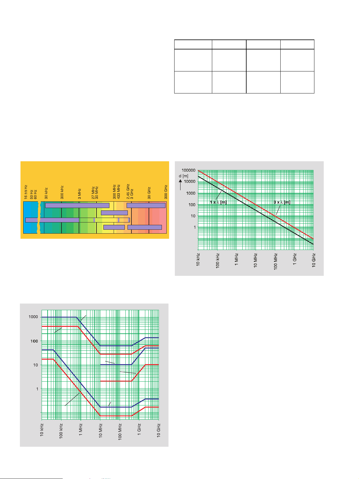
Near-field and far-field
Electromagnetic fields can be split into two components: the electric field E [measured in V/m] and the magnetic field H [measured
in A/m]. The E-field and H-field are strongly interdependent for the
far-field, i.e. anywhere more than a certain distance from the
source (see diagram). If, say, the H-field is measured in this
region, the magnitude of the E-field and the power density S
[W/m] can be calculated from it. In contrast, the H-field and E-field
must be measured separately in the near-field region.
waves (SHF)
Far-field
Near-field
2
2
Frequency ranges of electromagnetic radiation encountered
in everyday life.
Limit values
Work on defining legally binding limit values for electromagnetic
radiation is currently being done at national and international
levels. The limit values specified in the draft CENELEC European
standard are quoted here as an example.
E-field, workplace [V/m]
E-field,
public areas [V/m]
H-field,
public areas [A/m]0.1
Power density,
workplace [W/m
2
]
Power density,
public areas [W/m
H-field,
workplace [A/m]
2
]
Near-field and far-field definition. Measurements at a
distance d of 1 x wavelength ll (better: 3 x ll) from the source
are made under far-field conditions.
Applications and tips
± Induction heaters, RF welding equipment and erosion
machines: Electric fields are less important here, the magnetic
fields need to be monitored. Use EMR-10/EMR-10C Magnetic
Field Meter
± Radio and TV transmitters /antennas: As long as the location
is in the far-field region, an E-field sensor is preferable due to
the large bandwidth (EMR-20/EMR-30). When working close
to antennas (near-field) separate checking of the E-field and
the H-field is unavoidable (use EMR-20/EMR-30 for E-field,
EMR-10 for H-field)
± Diathermy equipment (RF equipment for medical therapy):
Very high field strengths are present at the electrodes and on
the connecting leads to the electrodes. The main component
is normally the electric field (use EMR-20/EMR-30).
± Microwave ovens: The very short wavelength means that
exposure is normally in the far-field. E-field measurements are
therefore sufficient (use EMR-20/EMR-30)
3 Limit values for electromagnetic radiation.
Further details are found in the draft European standard
CENELEC 50166-2.
Page 3

Spatial averaging
The spatial distribution of a field is seldom homogeneous, even
within the confines of a low-reflection absorber chamber.
Measurements at several points within the area are thus needed.
By measuring at different positions, it is also possible to estimate
complete body exposure levels. The root mean square of these
values is required. The EMR-30 makes light work of this. When
set to Spatial Averaging mode, a new measurement is made
simply by pressing a key. The squares of these values are summed
automatically, providing a display of the average field strength
for the area. If the ``Spatialº key is held down, the EMR-30 will
calculate the average for the time that the key was pressed.
All instruments in the EMR range are also equipped with an
averaging function for the 6-minute average specified by the
relevant standards.
PC Transfer Set
If high field strengths are to be measured or long-term monitoring
is required, the measured values can be transferred to a PC or
printer using an optical interface and the ETS-1 Transfer Set.
All products in the EMR range can also be fully remote-controlled
via this interface. The software supplied with the Transfer Set
makes it easy to record the results and then process them using
programs such as Excel. The EMR-30 can, in fact, store up
to 1500 measured values, complete with timestamp and all
parameters, so it is capable of monitoring for a whole day without
needing to be connected to a PC or printer. The results can be
displayed later or read out together with all major parameters by
using the ETS-1 Transfer Set.
The Transfer Set allows independent output of the measured
values, i.e. spatial field strength and the three measurement axes
X, Y and Z.
Spatial averaging
Non-directional measurement
Free-space electromagnetic fields are seldom due to a single
source, but are generally the result of several transmitters from
different directions. To be able to correctly determine the radiation
exposure, any measurement must be non-directional, i.e. isotropic. The value measured by an isotropic instrument is also not
affected by the position in which the instrument is used. For these
reasons, the probe of the EMR-20/EMR-30 is fitted with three
sensors which measure the field strength of the X, Yand Z directions separately. The field strength is calculated by the instrument's processor by summing the squares of the three measured
values. This method has the advantage over conventional analog
summing within the probe that all three sensors can be independently calibrated to achieve very high linearity. It also eliminates
dependence on the square-law sensor characteristic which leads
to large measurement errors as it no longer holds true at high field
strengths. Use of this novel, innovative method means that the
EMR-20 and EMR-30 can measure the entire field strength range
from 1 V/m to 800 V/m for the first time using just a single probe.
This simplifies measurement and makes the purchase of
additional probes unnecessary.
Zeroing
Normally, an instrument for measuring electromagnetic radiation
requires zeroing every time it is switched on or the temperature
changes, if accurate measurements are to be obtained. Up till
now, the instrument had to be placed in a room where no field
was present in order to zero it. More often than not, such a room
is not available, and the whole procedure is inconvenient. A new
zeroing method is used in the EMR range of products that is fully
automatic and which is also valid even in the presence of high
field strengths. The measurement errors due to inaccurate zeroing
can be excluded as far as the EMR range of instruments is
concerned.
Rugged casing
The casing is specially constructed to withstand shocks and
impacts, to allow use under difficult conditions, e.g. outdoors or
at industrial sites. The basic unit includes anti-slip, impactresistant shock protection. All mechanical connections such as
the test probe are designed to withstand rough handling. Practical
details like the tripod bush and built-in stand make the instrument
equally suitable for laboratory applications.
Page 4

Specifications* of the Radiation Meters EMR-20, EMR-30
Radiation measurement
Type ................................ electrical field (E)
Frequency range ...................... 100kHzto3GHz
Specified measurement principle . digital triaxial measurement
Directional pattern ............... isotropic, 3-dimensional
Measurement range
CW signals (f 4300 kHz) .............. 0.6V/mto800V/m
true RMS . . . ........................ 0.6V/mto20V/m
Range selection .............. onesingle continuous range
with 462 dB dynamic
Display resolution ............................ 0.01 V/m
Absolute error at 27.5 V/m and 27.12 MHz ..........+1dB
Linearity referred to 27.5 V/m and 27.12 MHz
from 0.6 V/m to 1.25 V/m . . . ...................+3dB
from 1.25 V/m to 2.5 V/m . . . ...................+1dB
from2.5V/mto400V/m .....................+0.5 dB
from400V/mto800V/m ....................+0.7 dB
Frequency response:
EMR-20C/-30C with consideration
of CAL factor and inclusive of calibration accuracy
from100kHzto100MHz ...................+0.45 dB
from100MHzto3GHz......................+1.4 dB
EMR-20/-30 with consideration of typical CAL factor
from100kHzto100MHz ....................+1.0 dB
from100MHzto1GHz......................+1.5 dB
from1GHzto3GHz ........................+2.4 dB
Isotropic deviation
Field sensor only .............. typ.+0.5 dB for f 41 MHz
Field sensor plus
radiation meter ................ typ.+1.0 dB for f 41 MHz
Temperature dependency (0 to +50 8C) ......... +0.2/±1dB
Overload protection CW / impulse ....0.7W/cm
2
/ 70 W/cm
Suppression H/E
from100kHzto5MHz .....435 dB ± 20 dB6log (f/MHz)
above 5 MHz........................ typically 420 dB
Settling time . ........ typically 1 s (0 to 90% of meas. value)
Display refresh rate . . . .................. typically 400 ms
Display and warning circuits
Display type . ................... LCD, instrument specific
Visible warning ........... bright red LEDs in the foil keypad
Audible warning .............. built-in piezoelectric device,
tone sequence depending on measured value
Measurement functions
Units ...........V/m, A/m, mW/cm
2
, W/m2, % of limit value
Detection . . . ............................ diode rectifier
Result display .............................current result
or maximum value since switch-on
Averaging . . . .......................... current result or
6-minute average
Alarm functions ..............variable threshold and on/off
Calibration data ..................oneCALfactor settable
Self tests
Automatic switch-on self test of
A/D converter, battery, supply voltages, memory and
zero adjustment.
Periodical zero adjustment and battery check during
operation.
All tests can be performed during exposure to the field.
Calibration
EMR-20/-30 with linearity calibration certificate and typical
CAL factors for frequency response included.
EMR-20C/-30C with calibration report and special calibration
of frequency response, isotropy and linearity.
Recommended confirmation interval ............24months
Interfaces
Serial interface for results transfer, remote operation
and calibration ...........V.24(RS232) optical/bidirectional
Additional functions EMR-30/EMR-30C
Result storage .............................1500 values
Real-time clock
Spatial averaging within a time period or over measurement
points.
General specifications
2
Power supply
Rechargeable batteries ..............26Mignon (AA) 1.2 V
Dry batteries . ......................26Mignon (AA) 1.5 V
Operating time
rechargeable / dry batteries. . . . ........... typ. 8 h / 415 h
Recharging . . ...........using NT-20 Charger Unit supplied
Ambient temperature
Operating range ............................ 0to+508C
Dimensions (w6h6d)inmm.......approx. 966646465
(incl. sensor and impact protection)
We i g h t (incl. batteries).. ................... approx. 450 g
* Unless otherwise stated, the data are valid for the following conditions:
sinusoidal signals;
instrument in the far-field of the source, sensor showing to the source;
ambient temperature 23 8C+3 8C;
relative air humidity 25 to 75 %.
Ordering information
EMR-20 Radiation Meter BN 2244/20
EMR-20C Radiation Meter BN 2244/70
with special calibration
EMR-30 Radiation Meter BN 2244/30
EMR-30C Radiation Meter BN 2244/80
with special calibration
Supplied with:
Impact protection with strap and tripod bush
NiCd cells, Mignon (AA) size
NT-20 Charger Unit (please specify type)
Euro version BN 2238/90.02
UK version BN 2238/90.03
US version BN 2238/90.04
Australian version BN 2238/90.05
Accessories:
Soft case BN 2244/60
Tripod, non-metallic BN 2244/90.31
Support, non-metallic BN 2244/90.32
Warning sign ªElectromagnetic Radiationº
large, 2 pieces BN 2244/90.36
small, 10 pieces BN 2244/90.37
ETS-1 PC Transfer Set BN 2244/90.33
(O/E converter, fiber cable, floppy disk)
NiCd/NiMH battery charger
(Euro version) BN 2237/90.03
Handheld test generator, 27 MHz BN 2244/90.38
Sensor extension, 1.2 m, flexible BN 2244/90.35
Storage case, aluminium-lined BN 2244/62
Safety Test Solutions
from Wandel & Goltermann
Subject to change without notice ± EM/EN/D028/09.99/AE/repl 935 ± Printed in Germany
 Loading...