

Page 1
Solid State Broadband High Power Amplifier
2157 - BBS4A5AVT
1000 – 2000 MHz / 1300 Watts
316 W. Florence Ave.
Inglewood, CA 90301
Ph. 1 (310) 412-8100
Fax. 1 (310) 412-9232
www.EmpowerRF.com
Stock No. 2157
D.S. Rev. 1.2 / 09-06-2011
Parameter
Symbol
Min
Typ
Max
Unit
Operating Frequency
BW
1000
2000
MHz
Power Output CW
P
SAT
1300
Watt
Gain @ Rated output power
GP
60
62 dB
Input Power for rated output power
PIN 0 dBm
Gain Flatness
G
±1.0
±1.5
dB
Gain Adjustment Range
VVA
20
25 dB
Input/Output Return Loss
S11 / S22
-10
dB
Noise Figure
NF 15 dB
Third Order Intercept Point
IP3 +65
dBm
Harmonics @ 1 dB Gain Compression Point
H -20
dBc
Spurious Signals
Spur -70
-60
dBc
Switching Time
TON / T
OFF
2
μSec
Operating Voltage (3 Phase) Delta Connection Line
to Line
VAC
180
208
264
Volt
AC Power Consumption @ 1300 W CW
PD 5000
6500
Watt
Parameter
Value
Limit
Dimensions W x H x D w/o enclosure
19” x 14” x 22” (432 x 35 x 560mm)
Typ
Weight
135 lb.
Max
RF Connectors Input / Output
TNC female / 16 mm DIN Female
I/O Control Connector
Dsub, 15 Pins, Male
Cooling
Built in forced-air system
LCD
Local: Front panel touch screen LCD controller including
Fwd/Rev Power indication (dB or Watt scale), Gain
Adjustment, ALC Fast/Slow & On/Off, Standby mode, Fault
indication.
Remote: Rear panel GPIB IEEE-488.2 or full duplex RS232
serial interface or Ethernet
Note: Output Power is lowered by 0.5-0.75dB with this
option.
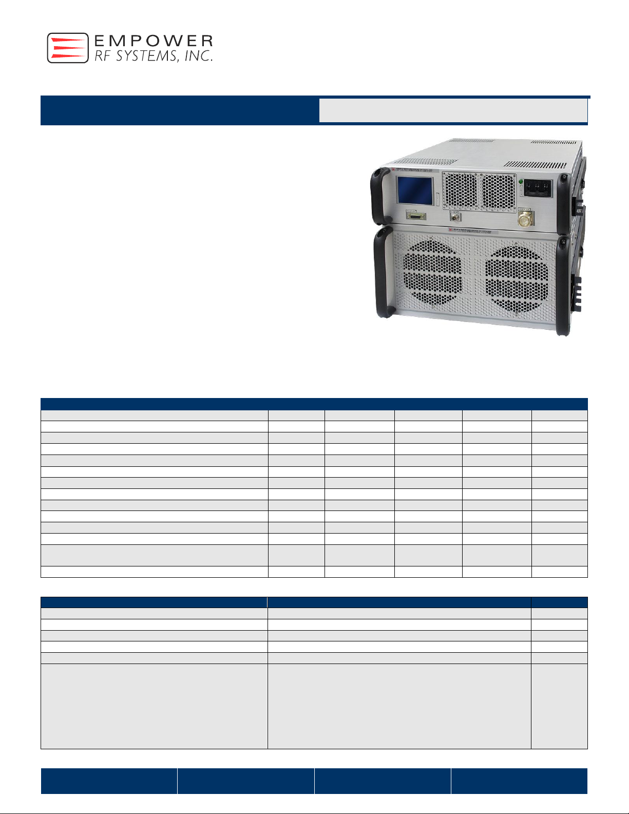
The BBS4A5AVT (SKU 2157) is suitable L & S Bands broadband or band
specific high power linear, CW and pulse applications. This amplifier
utilizes high power GaN devices that provide wide frequency response,
high gain, high peak power capability, and low distortions. Exceptional
performance, long-term reliability and high efficiency are achieved by
employing advanced broadband RF matching networks and combining
techniques, EMI/RFI filters, and all qualified components. The amplifier is
housed in two 19” rack mountable cabinets (LRU’s) and as a option can
be supplied in a rack cabinet. The larger LRU (5U) contains the RF power
section while the smaller LRU (3U) contains the main power supply and
control circuits. The system operates from a single phase power supply
and has built in control, monitoring and protection functions and forced air-
cooling system. Empower RF’s ISO9001 Quality Assurance Program
assures consistent performance and the highest reliability.
Solid-state linear design
Instantaneous broadband
Modular LRU design
Suitable for CW, AM and FM (for other modulation types, consult
factory).
50 ohm input/output impedance
High reliability and ruggedness
Built in Control, Monitoring and Protection Circuits
ELECTRICAL SPECIFICATIONS @ 208 VAC, 3, 25C, 50 System
MECHANICAL SPECIFICATIONS
Page 2
Solid State Broadband High Power Amplifier
2157 - BBS4A5AVT
1000 – 2000 MHz / 1300 Watts
316 W. Florence Ave.
Inglewood, CA 90301
Ph. 1 (310) 412-8100
Fax. 1 (310) 412-9232
www.EmpowerRF.com
Stock No. 2157
D.S. Rev. 1.2 / 09-06-2011
Parameter
Symbol
Min
Typ
Max
Unit
Operating Ambient Temperature
Tc 0
+50
°C
Storage Temperature
Tstg
-20 +85
°C
Relative humidity (condensing)
RH
95
%
Altitude (MIL-STD-810F Method 500.4)
ALT
8,000
30,000
Feet
Vibration
VI
MIL-STD-810F Method 514.5 Proc I random
sinusoidal Category 4 or 9 or 13
Shock
SH
MIL-STD-810F Method 516.4 Proc I
Operational: Acceleration (A) of 20.0 g ±1.5 g with
Duration of 11.0 ms ±1.0 ms shock pulse.
Non-Operational: Impact shocks of 25 g ±3.0 g
with Duration of 11.0 ms ±1.0 ms shock pulse.
Input Overdrive
+10 dBm
Max
Load VSWR @1000W
3:1 @ any angle & magnitude
Nom
Thermal Overload
85C shutdown
Max
Pin #
Description
Specifications
1
Forward TP
Analog Voltage 0-5 V Test Point relative to Forward Power Output
2
Reverse TP
Analog Voltage 0-5 V Test Point relative to Reverse Power
3
N/C
Spare
4
RS422 In (-) (S/D)
RS422 Serial Port In (-) External Shutdown
5
RS422 In (+) (S/D)
RS422 Serial Port In (+) External Shutdown
6
N/C
Reserved
7
N/C
Reserved
8
+5 V TP
Measurement Voltage Output 5 V
9
GND
Ground
10
+12 V TP
Measurement Voltage Output 12 V Test Point
11
RS422 In (+)
RS422 Serial Port Driver In (+) CPU
12
RS422 In (-)
RS422 Serial Port Driver In (-) CPU
13
RS422 Out (+)
RS422 Serial Port Driver Out (+) CPU
14
RS422 Out (-)
RS422 Serial Port Driver Out (-) CPU
15
+28V TP
Measurement Voltage Output 28 V Test Point
Pin #
Description
Specifications
1
N/C
2
RS-232 RX
Receive Data
3
RS-232 TX
Transmit Data
4
N/C 5
GND
Signal Ground
6
N/C
7
RS-232 RTS
Request to Send
8
RS-232 CTS
Clear to Send
9
N/C
ENVIRONMENTAL CHARACTERISTICS (Design to Meet)
PROTECTIONS
I/O CONNECTOR – D-sub, 15 Pin
Remote Control RS-232 – J14- D-sub, 9 Socket
Page 3

Solid State Broadband High Power Amplifier
2157 - BBS4A5AVT
1000 – 2000 MHz / 1300 Watts
316 W. Florence Ave.
Inglewood, CA 90301
Ph. 1 (310) 412-8100
Fax. 1 (310) 412-9232
www.EmpowerRF.com
Stock No. 2157
D.S. Rev. 1.2 / 09-06-2011
Pin #
Description
Specifications
A
Phase 1
208 VAC
B
Phase 2
208 VAC
C
Phase 3
208 VAC
D
GND
Ground
Pin #
Description
Specifications
1
DIO 1
Data Input / Output bit.
2
DIO 5
Data Input / Output bit.
3
DIO 2
Data Input / Output bit.
4
DIO 6
Data Input / Output bit.
5
DIO 3
Data Input / Output bit.
6
DIO 7
Data Input / Output bit.
7
DIO 4
Data Input / Output bit.
8
DIO 8
Data Input / Output bit.
9
EOI
End-or-identity
10
REN
Remote Enable
11
DAV
Data Valid
12
GND 13
NRFD
Not ready for data
14
GND
15
NDAC
Not data accepted
16
GND 17
IFC
Interface Clear
18
GND
(DAV)
19
SRQ
Service Request
20
GND
(NDAC)
21
ATN
Attention
22
GND
(SRQ)
23
GND
(ATN)
24
GND
Signal Ground
AC Power CONNECTOR- J2
Remote Control HPIB IEEE-488.2 – J15
Page 4

Solid State Broadband High Power Amplifier
2157 - BBS4A5AVT
1000 – 2000 MHz / 1300 Watts
316 W. Florence Ave.
Inglewood, CA 90301
Ph. 1 (310) 412-8100
Fax. 1 (310) 412-9232
www.EmpowerRF.com
Stock No. 2157
D.S. Rev. 1.2 / 09-06-2011
SYSTEM Block Diagram
SYSTEM OUTLINE DRAWING - OUTLINE
Page 5

Solid State Broadband High Power Amplifier
2157 - BBS4A5AVT
1000 – 2000 MHz / 1300 Watts
316 W. Florence Ave.
Inglewood, CA 90301
Ph. 1 (310) 412-8100
Fax. 1 (310) 412-9232
www.EmpowerRF.com
Stock No. 2157
D.S. Rev. 1.2 / 09-06-2011
SYSTEM OUTLINE DRAWING - REAR VIEW
Page 6

Solid State Broadband High Power Amplifier
2157 - BBS4A5AVT
1000 – 2000 MHz / 1300 Watts
316 W. Florence Ave.
Inglewood, CA 90301
Ph. 1 (310) 412-8100
Fax. 1 (310) 412-9232
www.EmpowerRF.com
Stock No. 2157
D.S. Rev. 1.2 / 09-06-2011
Plots 1 - Small Signal and P
1dB
Gain
Top Curve: Small Signal Gain @ PIN = -20dBm
Middle Curve: Power Gain @ P
1dB
, PIN = -15 dBm (Note 2, 3)
Reference: 66dB, 1dB/Div.
Bottom Curve: Input Return Loss
Reference: 0dB, 10dB/Div.
Plot 2 - Small Signal and P
SAT
Top Curve: Small Signal Gain @ PIN = -20dBm
Bottom Curve: Power Gain @ P
SAT
, PIN = 1.0dBm (Note 2, 3)
Reference: 64dB, 1dB/Div.
Middle Curve: Input Return Loss
Reference: 0dB, 10dB/Div.
Plot 3 - Gain Adjustment Range
Top Curve: Maximum Gain @ PIN = -20dBm
Middle Curve: VVA @ Minimum Gain
Reference: 40dB, 10dB/Div.
Bottom Curve: Input Return Loss
Reference: 0dB, 10dB/Div.
Plot 4 - ALC Flatness @ 1000W & 200W
Top Curve: ALC @ 1000W, PIN = 0dBm
Middle Curve: ALC @ 200W, PIN = 0dBm
Reference: 56dB, 1dB/Div.
Middle Curve: Input Return Loss
Reference: 30dB, 10dB/Div.
Notes: 2. Source correction included in PIN measurement: 0.0dB @ 2000MHz
Performance Plots
3. Output Directional Coupler may reduce Power Capability by 0.5-0.75dB
 Loading...