

Page 1
Features:
l
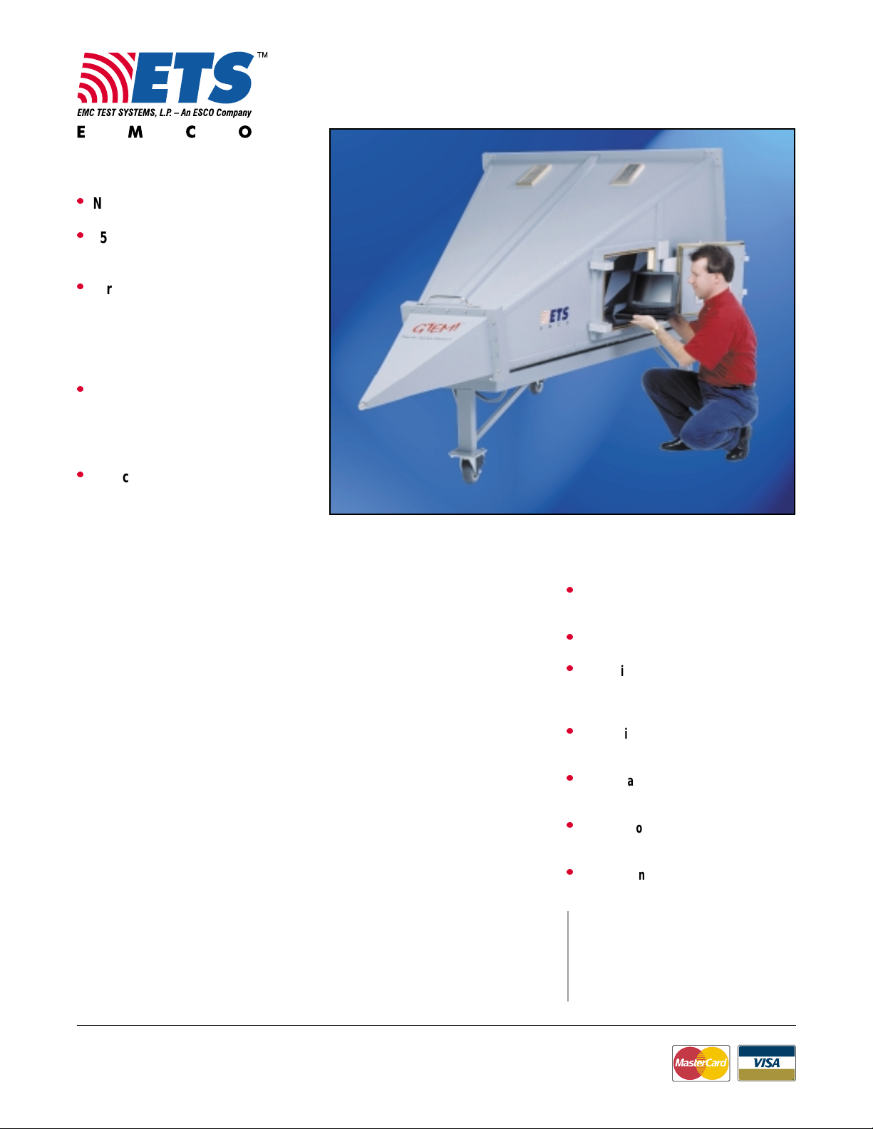
New Sizes, Lower Price
RF Emissions/Immunity Test Cell
TM
GTEM! Models 5405/5407
l
25x25x25 cm3 or 40x40x40 cm
3
EUT Test Volumes
l
For All Phases of EMC Testing:
- Design Qualification
- Pre-Compliance
- Full Compliance
- Post Production
l
For Full Compliance Demonstration of:
- IEC 61000-4-3, EN 61000-4-3,
- MIL-STD 462, ANSI C63.4,
- EN 55022 and VDE 0871
l
Reduces Test Time
≈≈
-
≈ 8:1 for RE (vs. OATS)
≈≈
≈≈
-
≈ 2:1 for RI (vs. chamber)
≈≈
EMCO’s Model 5405 and 5407 GTEM!
TM
Cells enable users to perform radiated
emissions and radiated immunity tests
in less time than at either an OATS or i n a
chamber. Tests can be performed quickly
and accurately throughout the product
life cycle. Beginning with design
qualification testing and moving through
to pre-compliance testing, full compliance testing and production sampling,
EMCO’s GTEM! cells are time-sa ving
devices for your test lab. A typical
radiated emiss ions test (10,000 point
scan) can be completed in 15 minutes or
less, while a typical radiated immunity
test can usually be completed in h alf the
normal time.
The GTEM! is based on experience, not
experimentation. Originally developed in
the EMC Baden (Switzerland) labs of
ABB, the cell has been accepted in the
EMC community for more than 10 years,
New Model 5405
and is field proven daily at more than
400 installation s worldwide. Measurements mad e with a GTEM! are accepted
for final compliance demo nstration by
the FCC for Part 15 & 18 radiated
emissions testing, and comply with IEC
61000-4-3 Annex D for immunity testing.
The GTEM!’s unique taper ed shape,
offset septum, r e sisti v e termination
network and absorber-lined backwall
remove performance lim i tations of TEM
cells and boxy enclosures. Electromagnetic wave and RF current termination
are smooth and controlled. Field
uniformity is ± 3 dB up to 1 GHz, and
± 4 dB above 1 GHz.
These new models are the result of an
on-going program of research and
development. The new s izes are a resu l t
of customer requirements, while the
lower price is a result of pr ocess and
material im prov e m en ts.
Standard Configuration
l
GTEM! cell with door placement on
right side (viewed from feed)
l
Mobile base with locking caster wheels
l
Hydraulically damped door with
recessed contact mechanism, contact
RF sealing and shielded window
l
Rantec high performance RF anechoic
absorber
l
Single phase, 20A, 50/60 Hz filter with
choice of two floor mounted receptacles
l
One wall mounted fiber optic
feedthrough (4 lines)
l
Three N connector feedthroughs
For a performance comparison of the
TM
and several contemporary TEM
GTEM!
devices, request a reprint of a paper by Dr. H.
Garbe, University of Hannover, Field
Homogeneity in Different TEM Waveguides.
USA:
Tel +1.512.835.4684
Fax +1.512.835.4729
Information presented is subject to change as product enhancements are made. Contact ETS Sales Department for current specifications.Information presented is subject to change as product enhancements are made. Contact ETS Sales Department for current specifications.
Information presented is subject to change as product enhancements are made. Contact ETS Sales Department for current specifications.
Information presented is subject to change as product enhancements are made. Contact ETS Sales Department for current specifications.Information presented is subject to change as product enhancements are made. Contact ETS Sales Department for current specifications.
FINLAND:
Tel +358.2.8383.300
Fax +358.2.8651.233
ONLINE:
info@ emctest.com
http://www.emctest.com
2/00 - 1k S © 2000 ETS-EMCO REV-A2/00 - 1k S © 2000 ETS-EMCO REV-A
2/00 - 1k S © 2000 ETS-EMCO REV-A
2/00 - 1k S © 2000 ETS-EMCO REV-A2/00 - 1k S © 2000 ETS-EMCO REV-A
11
1
11
Page 2
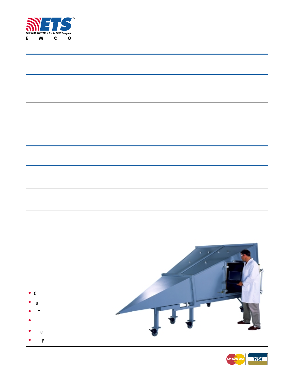
RF Emissions/Immunity Test Cell
TM
GTEM! Models 5405/5407
Electric al Specifications
MODEL FREQUENCY VSWR MAXIMUM INPUT FEED SHIELDING
RANGE TYPICAL CW INPUT IMPEDANCE CONNECTOR EFFECTIVENESS
POWER TYPE
11
1
11
5405 5405
5405 9 kHz – 5 GHz
5405 5405
RI TESTS
DC – 20 GHz
RE TESTS
RE TESTS
5407 5407
5407 9 kHz – 5 GHz
5407 5407
RI TESTS
DC – 20 GHz
CHARACTERISTIC FREQ
22
2
22
11
1
11
CHARACTERISTIC FREQ
22
2
22
≤≤
≤ 1.75:1 50
≤≤
ALL OTHER FREQ 400 W TO N JACK 80 dB MINIMUM
≤≤
≤ 1.3:1 W/ OPT. BLOWER ADAPTER 10 kHz – 1 GHz
≤≤
≤≤
≤ 1.75:1 50
≤≤
ALL OTHER FREQ 500 W TO N JACK 80 dB MINIMUM
≤≤
≤ 1.3:1 W/ OPT. BLOWER ADAPTER 10 kHz – 1 GHz
≤≤
Physical Specifications
MODEL OUTER DOOR HIGHEST ACCURACY APPROX MAXIMUM DISTRIB
CELL DIMENSION TRANSVERSE TEST SURFACE CELL SEPTUM LOAD
DIMENSION IN CENTER OF CELL
3
3
250 W
200 W
Ω 7/16
Ω 7/16
4
WEIGHT HEIGHT
CW CW
CW FROM
CW CW
DIN PLUG INTERNAL E-FIELDS
CW CW
CW FROM
CW CW
DIN PLUG INTERNAL E-FIELDS
5
RATING
6
(L) 3.0 m (9.8 ft) 250 kg 550.0 mm 250 kg
5405 (W) 1.6 m (5.2 ft) (W) 460 mm (18.1 in) (W) 300 mm (11.8 in) (551 lb) (21.7 in) (551 lb)
(H) 1.7 m (5.6 ft) W BASE (H) 385 mm (15.2 in) (H) 300 mm (11.8 in)
(H) 1.1 m (3.7 ft) W/O BASE
(L) 4.0 m (13.10 ft) 500 kg 900.0 mm 430 kg
5407 (W) 2.2 m (7.1 ft) (W) 686 mm (27.0 in) (W) 400 mm (15.8 in) (1100 lb) (35.4 in) (950 lb)
(H) 2.1 m (6.8 ft) W BASE (H) 747 mm (29.4 in) (H) 400 mm (15.8 in)
(H) 1.4 m (4.6 ft) W/O BASE
1
Frequency range where OATS correlation demonstrated:
3-position algorithm 30 MHz - 5 GHz, 9-position
algorithm 9kHz - 5 GHz
2
Low VSWR to f ≥ 20 GHz; subject to field uniformity
tolerance
3
Characteristic frequency: resistor board/RF absorber
crossover frequency
4
≤ 8 dB Uniformity
5
At resistor board junction
6
Total EUT and personnel load distributed at maximum
loading of 450 kg/m2. Point loads less than 7 cm2 should
not exceed 20 kg/cm2.
Note:
The 5405 is shipped fully assembled. Please note dimensions
in the Physical Specifications table to ensure the unit will fit
through your doorways. As standard, the 5407 is shipped partially
assembled with instructions for installation. Doorways that are
218.5 cm (86 in) wide and 203.2 cm (80 in) high are needed for
subassembly passage. If space limitations exist, the unit can be
shipped unassembled. Contact EMCO sales department regarding
requests to ship the unit unassembled and for supervision of
installation.
Options
l
Custom Electrical Filters
l
Custom Feedthrough Panels
l
EUT XYZ Axis Positioning Device
l
EUT Illumination
l
Forced Ventilation
l
High Power Configuration
USA:
Tel +1.512.835.4684
Fax +1.512.835.4729
Information presented is subject to change as product enhancements are made. Contact ETS Sales Department for current specifications.Information presented is subject to change as product enhancements are made. Contact ETS Sales Department for current specifications.
Information presented is subject to change as product enhancements are made. Contact ETS Sales Department for current specifications.
Information presented is subject to change as product enhancements are made. Contact ETS Sales Department for current specifications.Information presented is subject to change as product enhancements are made. Contact ETS Sales Department for current specifications.
FINLAND:
Tel +358.2.8383.300
Fax +358.2.8651.233
ONLINE:
info@ emctest.com
http://www.emctest.com
Model 5407
2/00 - 1k S © 2000 ETS-EMCO REV-A2/00 - 1k S © 2000 ETS-EMCO REV-A
2/00 - 1k S © 2000 ETS-EMCO REV-A
2/00 - 1k S © 2000 ETS-EMCO REV-A2/00 - 1k S © 2000 ETS-EMCO REV-A
22
2
22
 Loading...