

Page 1

Z170-AR
Motherboard
Page 2

E10395
First Edition
July 2015
Copyright © 2015 ASUSTeK COMPUTER INC. All Rights Reserved.
No part of this manual, including the products and software described in it, may be reproduced,
transmitted, transcribed, stored in a retrieval system, or translated into any language in any form or by any
means, except documentation kept by the purchaser for backup purposes, without the express written
permission of ASUSTeK COMPUTER INC. (“ASUS”).
Product warranty or service will not be extended if: (1) the product is repaired, modied or altered, unless
such repair, modication of alteration is authorized in writing by ASUS; or (2) the serial number of the
product is defaced or missing.
ASUS PROVIDES THIS MANUAL “AS IS” WITHOUT WARRANTY OF ANY KIND, EITHER EXPRESS
OR IMPLIED, INCLUDING BUT NOT LIMITED TO THE IMPLIED WARRANTIES OR CONDITIONS OF
MERCHANTABILITY OR FITNESS FOR A PARTICULAR PURPOSE. IN NO EVENT SHALL ASUS, ITS
DIRECTORS, OFFICERS, EMPLOYEES OR AGENTS BE LIABLE FOR ANY INDIRECT, SPECIAL,
INCIDENTAL, OR CONSEQUENTIAL DAMAGES (INCLUDING DAMAGES FOR LOSS OF PROFITS,
LOSS OF BUSINESS, LOSS OF USE OR DATA, INTERRUPTION OF BUSINESS AND THE LIKE),
EVEN IF ASUS HAS BEEN ADVISED OF THE POSSIBILITY OF SUCH DAMAGES ARISING FROM ANY
DEFECT OR ERROR IN THIS MANUAL OR PRODUCT.
SPECIFICATIONS AND INFORMATION CONTAINED IN THIS MANUAL ARE FURNISHED FOR
INFORMATIONAL USE ONLY, AND ARE SUBJECT TO CHANGE AT ANY TIME WITHOUT NOTICE,
AND SHOULD NOT BE CONSTRUED AS A COMMITMENT BY ASUS. ASUS ASSUMES NO
RESPONSIBILITY OR LIABILITY FOR ANY ERRORS OR INACCURACIES THAT MAY APPEAR IN THIS
MANUAL, INCLUDING THE PRODUCTS AND SOFTWARE DESCRIBED IN IT.
Products and corporate names appearing in this manual may or may not be registered trademarks or
copyrights of their respective companies, and are used only for identication or explanation and to the
owners’ benet, without intent to infringe.
Offer to Provide Source Code of Certain Software
This product contains copyrighted software that is licensed under the General Public License (“GPL”),
under the Lesser General Public License Version (“LGPL”) and/or other Free Open Source Software
Licenses. Such software in this product is distributed without any warranty to the extent permitted by the
applicable law. Copies of these licenses are included in this product.
Where the applicable license entitles you to the source code of such software and/or other additional data,
you may obtain it for a period of three years after our last shipment of the product, either
(1) for free by downloading it from http://support.asus.com/download
or
(2) for the cost of reproduction and shipment, which is dependent on the preferred carrier and the location
where you want to have it shipped to, by sending a request to:
ASUSTeK Computer Inc.
Legal Compliance Dept.
15 Li Te Rd.,
Beitou, Taipei 112
Taiwan
In your request please provide the name, model number and version, as stated in the About Box of the
product for which you wish to obtain the corresponding source code and your contact details so that we
can coordinate the terms and cost of shipment with you.
The source code will be distributed WITHOUT ANY WARRANTY and licensed under the same license as
the corresponding binary/object code.
This offer is valid to anyone in receipt of this information.
ASUSTeK is eager to duly provide complete source code as required under various Free Open Source
Software licenses. If however you encounter any problems in obtaining the full corresponding source
code we would be much obliged if you give us a notication to the email address gpl@asus.com, stating
the product and describing the problem (please DO NOT send large attachments such as source code
archives, etc. to this email address).
ii
Page 3

Contents
Safety information ....................................................................................................... v
About this guide .......................................................................................................... v
Package contents ...................................................................................................... vii
Z170-AR specifications summary ............................................................................ vii
Chapter 1: Product Introduction
1.1 Before you proceed ...................................................................................1-1
1.2 Motherboard overview ............................................................................... 1-1
1.3 Central Processing Unit (CPU) .................................................................1-4
1.4 System memory .........................................................................................1-8
1.5 Expansion slots ........................................................................................1-16
1.6 Jumpers .................................................................................................... 1-19
1.7 Connectors ............................................................................................... 1-21
1.8 Onboard LEDs .......................................................................................... 1-34
1.9 Onboard buttons and switches ..............................................................1-36
1.10 Software support ......................................................................................1-39
Chapter 2: BIOS Setup
2.1 Knowing BIOS ............................................................................................ 2-1
2.2 BIOS setup program .................................................................................. 2-2
2.2.1 EZ Mode......................................................................................2-3
2.2.2 Advanced Mode ..........................................................................2-4
2.2.3 QFan Control...............................................................................2-7
2.2.4 EZ Tuning Wizard .......................................................................2-9
2.3 My Favorites ............................................................................................. 2-12
2.4 Main menu ................................................................................................2-14
2.5 Ai Tweaker menu ......................................................................................2-16
2.6 Advanced menu .......................................................................................2-32
2.6.1 CPU Conguration ....................................................................2-33
2.6.2 Platform Misc Conguration ......................................................2-35
2.6.3 System Agent (SA) Conguration .............................................2-37
2.6.4 PCH Conguration ....................................................................2-38
2.6.5 PCH Storage Conguration.......................................................2-38
2.6.6 USB Conguration ....................................................................2-40
2.6.7 Network Stack Conguration.....................................................2-41
2.6.8 Onboard Devices Conguration ................................................2-41
2.6.9 APM Conguration ....................................................................2-44
2.6.10 HDD/SSD SMART Information .................................................2-45
2.6.11 Intel(R) Thunderbolt ..................................................................2-45
iii
Page 4

2.7 Monitor menu ...........................................................................................2-46
2.8 Boot menu ................................................................................................2-51
2.9 Tool menu ................................................................................................. 2-57
2.9.1 ASUS EZ Flash 3 Utility ............................................................2-57
2.9.2 Secure Erase ............................................................................2-57
2.9.3 ASUS O.C. Prole .....................................................................2-59
2.9.4 ASUS DRAM SPD Information .................................................2-60
2.9.5 Graphics Card Information ........................................................2-60
2.10 Exit menu .................................................................................................. 2-61
2.11 Updating BIOS .......................................................................................... 2-62
2.11.1 EZ Update .................................................................................2-62
2.11.2 ASUS EZ Flash 3 ......................................................................2-63
2.11.3 ASUS CrashFree BIOS 3 ..........................................................2-65
2.12 Installing an operating system ...............................................................2-66
2.12.1 Windows® 7 and USB 3.0 driver for 100 Series ........................ 2-66
Appendices
Notices .................................................................................................................... A-1
ASUS contact information ...................................................................................... A-5
iv
Page 5

Safety information
Electrical safety
• To prevent electrical shock hazard, disconnect the power cable from the electrical outlet
before relocating the system.
• When adding or removing devices to or from the system, ensure that the power cables
for the devices are unplugged before the signal cables are connected. If possible,
disconnect all power cables from the existing system before you add a device.
• Before connecting or removing signal cables from the motherboard, ensure that all
power cables are unplugged.
• Seek professional assistance before using an adapter or extension cord. These devices
could interrupt the grounding circuit.
• Ensure that your power supply is set to the correct voltage in your area. If you are not
sure about the voltage of the electrical outlet you are using, contact your local power
company.
• If the power supply is broken, do not try to x it by yourself. Contact a qualied service
technician or your retailer.
Operation safety
• Before installing the motherboard and adding components, carefully read all the manuals
that came with the package.
• Before using the product, ensure all cables are correctly connected and the power
cables are not damaged. If you detect any damage, contact your dealer immediately.
• To avoid short circuits, keep paper clips, screws, and staples away from connectors,
slots, sockets and circuitry.
• Avoid dust, humidity, and temperature extremes. Do not place the product in any area
where it may be exposed to moisture.
• Place the product on a stable surface.
• If you encounter technical problems with the product, contact a qualied service
technician or your retailer.
About this guide
This user guide contains the information you need when installing and conguring the
motherboard.
How this guide is organized
This guide contains the following parts:
• Chapter1:Productintroduction
This chapter describes the features of the motherboard and the new technology it
supports. It includes descriptions of the switches, jumpers, and connectors on the
motherboard.
• Chapter2:BIOSsetup
This chapter discusses changing system settings through the BIOS Setup menus.
Detailed descriptions for the BIOS parameters are also provided.
v
Page 6

Where to find more information
Refer to the following sources for additional information and for product and software
updates.
1. ASUS websites
The ASUS website provides updated information on ASUS hardware and software
products. Refer to the ASUS contact information.
2. Optional documentation
Your product package may include optional documentation, such as warranty yers,
that may have been added by your dealer. These documents are not part of the
standard package.
Conventions used in this guide
To ensure that you perform certain tasks properly, take note of the following symbols used
throughout this manual.
DANGER/WARNING: Information to prevent injury to yourself when
completing a task.
CAUTION: Information to prevent damage to the components when
completing a task
IMPORTANT: Instructions that you MUST follow to complete a task.
NOTE: Tips and additional information to help you complete a task.
Typography
Bold text
Italics
<Key> Keys enclosed in the less-than and greater-than sign
<Key1> + <Key2> + <Key3> If you must press two or more keys simultaneously, the key
vi
Indicates a menu or an item to select.
Used to emphasize a word or a phrase.
means that you must press the enclosed key.
Example: <Enter> means that you must press the Enter or
Return key.
names are linked with a plus sign (+).
Page 7

Package contents
Check your motherboard package for the following items:
Motherboard
Cables
ASUS Z170-AR Motherboard
2 x Serial ATA 6.0 Gb/s cables
1 x ASUS SLI bridge connector
Accessories
2-in-1 Q-connector
M.2 screw package
CPU installation tool
Application DVD
Documentation
If any of the above items is damaged or missing, contact your retailer.
Support DVD
User Guide and Feature Manual
Z170-AR specifications summary
LGA1151 socket for 6th Generation Intel® Core™ i7/ i5/ i3/Pentium®/Celeron®
Processors
CPU
Chipset
Memory
Expansion
Slots
VGA
Supports 14nm CPU
Supports Intel® Turbo Boost Technology 2.0*
* The Intel® Turbo Boost Technology 2.0 support depends on the CPU types.
Intel® Z170 Express Chipset
4 x DIMM, max. 64GB, DDR4 3400(O.C.)*/3333(O.C.)*/3200(O.C.)*/3100(O.C.)*/
3000(O.C.)*/2933(O.C.)*/2800(O.C.)*/2666(O.C.)*/2600(O.C.)*/2400(O.C.)*/2133
MHz, non-ECC, un-buffered memory
Dual channel memory architecture
Supports Intel® Extreme Memory Prole (XMP)
* Hyper DIMM support is subject to the physical characteristics of individual CPUs.
Please refer to Memory QVL (Qualified Vendors List) for details.
2 x PCI Express 3.0/2.0 x16 slots (single at x16 or dual at x8/x8 mode)
1 x PCI Express 3.0/2.0 x16 slot* (max. at x4 mode, compatible with PCIe x1 and
x4 devices)
3 x PCI Express 3.0/2.0 x1 slots
1 x PCI slot
* The PCIe x16_3 slot shares bandwidth with SATA6G_56. The PCIe x16_3 is default set
at x2 mode.
Integrated Graphics Processor- Intel® HD Graphics support
Multi-VGA output support: DisplayPort/HDMI ports
Supports DisplayPort 1.2* with max. resolution 4096 x 2304@60Hz/24Hz
Supports HDMI 1.4b with max. resolution 4096 x 2160@24Hz / 2560 x
1600@60Hz
(continued on the next page)
vii
Page 8

Z170-AR specifications summary
Supports Intel® InTru™ 3D/Quick Sync Video/Clear Video HD Technology/Insider™
Supports up to 2 displays simultaneously
VGA
Multi-GPU
Support
Storage
LAN
Audio
Maximum shared memory of 512MB
* DP 1.2 Multi-Stream Transport compliant, supports DP 1.2 monitor daisy chain up to 3
displays.
Supports NVIDIA® 2-way / Quad-GPU SLI™ Technology (with 2 PCIex16 graphics
cards)
Supports AMD® 3-way / Quad-GPU CrossFireX™ Technology
Intel® Z170 Express Chipset with RAID 0, 1, 5, 10 and Intel Rapid Storage
Technology 14 support
- 1 x SATA Express port (compatible with 2 x SATA 6.0 Gb/s ports)
- 6 x SATA 6.0 Gb/s ports(gray, 2 from SATA Express)
- Supports Intel® Smart Response Technology*
- 1 x M.2 Socket 3 with M Key**, type 2242/2260/2280/22110 storage devices
support (both SATA & PCIE mode)***
* These functions will work depending on the CPU installed.
** Supports PCIE RAID configurations via onboard M.2 and PCIex16_3.
*** M.2 shares SATA mode with SATA Express. Change this item before installing M.2
SATA devices.
Gigabit Intel LAN connection- 802.3az Energy Efcient Ethernet (EEE) appliance
Intel® I219-V Gigabit LAN- Dual interconnect between the integrated Media Access
Controller (MAC) and physical layer (PHY)
ASUS LAN Guard
ASUS Turbo LAN Utility
Realtek® ALC892 8-channel high definition audio CODEC featuring Crystal
Sound 3
- Power pre-regulator reduces power input noise to ensure consistent performance
- Separate layer for left and right track, ensuring both sound deliver equal quality
- Top notch audio sensation delivers according to the audio conguration
- Audio shielding ensures precise analog/digital separation and greatly reduced
multi-lateral interference
- EMI protection cover to prevent electrical noise to affect the amplier quality
- Audio Amplier to enhance the highest quality sound for headphone and
speakers
- Unique de-pop circuit to reduce start-up popping noise to audio outputs
- Premium Japan-made audio capacitors provides warm, natural, and immersive
sound with exceptional clarity and delity
- Absolute Pitch 192khz/24bit true BD lossless sound
- DTS Studio Sound™
- DTS Connect
- Supports jack-detection, multi-streaming, front panel jack-retasking (MIC)
- Optical S/PDIF out port at back I/O
viii
(continued on the next page)
Page 9

Z170-AR specifications summary
Intel® Z170 Express Chipset- supports ASUS USB 3.1 Boost
- 6 x USB 3.0/2.0 ports (4 ports at mid-board, 2 ports at back panel, blue)
USB
ASUS
Exclusive
Features
- 6 x USB 2.0/1.1 ports (4 ports at mid-board, 2 ports at back panel)
ASMedia® USB 3.1 controllers- supports ASUS USB 3.1 Boost and 3A
power output
- 1 x USB 3.1/3.0/2.0 ports at back panel (teal blue, Type-A)
- 1 x USB 3.1/3.0/2.0 port at back panel (Type-C)
Superb Performance
OC Design - ASUS PRO Clock Technology
- Full BCLK range for extreme overclocking performance
5-Way Optimization
- Whole system optimization with a single click! Perfectly consolidates better
CPU performance, power saving, digital power control, system cooling and
app usages.
DIGI+ VRM
-CPU Power: Digital 8-phase power design
-iGPU Power: Digital 2-phase power design
TPU
- Auto Tuning, TPU, GPU Boost, 2-level TPU switch
EPU
- EPU
Fan Xpert 3 featuring Fan Auto Tuning function and multiple thermistors
selection for optimized system cooling control
Turbo App featuring system performance tuning, network priority, and audio
scene conguration for selected applications.
UEFI BIOS
- Most advanced options with fast response time
Special Memory O.C. Design
- Superb memory O.C. capability under full load by minimizing the coupling
noise and signal reection effect
PC Cleaner
- Fast and easy way to get rid of unnecessary junk les
Remote Entertainment
Remote GO!
- Remote GO! Function: Cloud GO!, Remote Desktop, Remote Keyboard &
Mouse, File Transfer
- Wi-Fi GO! & NFC Remote app for portable smartphone/tablet, supporting iOS 7
& Android 4.0 systems
Media Streamer
- Pipe music or movies from your PC to a smart TV, your entertainment goes
wherever you go!
- Media Streamer app for portable smartphone/tablet, supporting iOS 7 &
Android 4.0 systems
HyStream
- Stream iOS devices’ screen on your PC screen.*
* Contact your device vendor for supporting information.
(continued on the next page)
ix
Page 10

Z170-AR specifications summary
eSports Champions
Turbo LAN
- Fast and smooth online gaming with lower pings and less lags
Crystal Sound 3
- Hear the cleanest sound with dedicated audio design onboard!
Turbo APP
- Tailored app performance, network priority and audio conguration for your
needs
EZ DIY
ASUS
Exclusive
Features
ASUS Special
Features
Push Notice
- Monitor your PC status with smart devices in real time
USB BIOS Flashback Card supported
UEFI BIOS EZ Mode featuring friendly graphics user interface
- TPU
- CrashFree BIOS 3
- EZ Flash 3
ASUS Q-Design
- ASUS Q-LED (CPU, DRAM, VGA, Boot Device LED)
- ASUS Q-Slot
- ASUS Q-DIMM
- ASUS Q-Connector
ASUS 5X Protection
- ASUS DIGI+ VRM - 8 Phase digital power design
- ASUS Enhanced DRAM Overcurrent Protection - Short circuit damage
prevention
- ASUS ESD Guards - Enhanced ESD protection
- ASUS High-Quality 5K-Hour Solid Capacitors - 2.5x long lifespan with excellent
durability
- ASUS Stainless Steel Back I/O - 3x more durable corrosion-resistant coating
Special Features
- Mobo Connect
- LAN Guard
- USB 3.1 Boost
- Ai Charger+
- AI Suite 3
- MemOK!
- EZ XMP
(continued on the next page)
x
Page 11

Z170-AR specifications summary
ASUS Quiet
Thermal
Solution
ASUS
Exclusive
Overclocking
Features
Rear Panel I/O
Ports
Internal I/O
Connectors
Quiet Thermal Design:
- ASUS Fan Xpert 3
- ASUS Fanless Design: Heat-sink solution
Precision Tweaker 2:
- CPU Core/Cache Voltage: Adjustable CPU Core/Cache Voltage at 0.005V
increment
- CPU Graphics Voltage: Adjustable CPU Graphics voltage at 0.005V increment
- CPU VCCIO Voltage: Adjustable CPU VCCIO Voltage at 0.0125V increment
- CPU System Agent Voltage: Adjustable CPU System Agent Voltage at
0.0125V increment
- DRAM Voltage: 152-step Memory voltage control
- PCH Core Voltage: 88-step Chipset voltage control
SFS (Stepless Frequency Selection)
- BCLK/PCIE frequency tuning from 40MHz up to 500MHz at 0.01MHz
increment
Overclocking Protection:
- ASUS C.P.R.(CPU Parameter Recall)
1 x PS/2 Keyboard/mouse combo port
1 x DisplayPort
1 x HDMI port
1 x Optical S/PDIF out
1 x Intel LAN (RJ45) ports
1 x USB 3.1/3.0/2.0 ports (teal blue, Type A)
1 x USB 3.1/3.0/2.0 ports (Type C)
2 x USB 3.0/2.0 ports (blue)
2 x USB 2.0 ports
8-channel Audio I/O ports
2 x USB 3.0/2.0 connectors support additional 4 USB ports (19-pin)
2 x USB 2.0/1/1 connectors support additional 4 USB ports
1 x M.2 Socket 3 (for M Key, type 2242/2260/2280/22110 storage devices)
1 x SATA Express connectors (gray)
4 x SATA 6.0Gb/s connectors (gray)
1 x CPU Fan connector (4-pin) for both 3-pin(DC mode) and 4-pin(PWM mode)
CPU coolers control with auto detection support
1 x CPU OPT Fan connector (4-pin)
1 x Water Pump header (3-pin)
4 x Chassis Fan connectors (4-pin) for both 3-pin(DC mode) and 4-pin(PWM
mode) coolers control
1 x Front panel audio connector (AAFP)
(continued on the next page)
xi
Page 12

Z170-AR specifications summary
1 x BIOS Flashback header
1 x S/PDIF out header
1 x Thunderbolt header (5-pin) for ASUS ThunderboltEX series support
1 x TPM connector
1 x COM port
1 x 24-pin EATX Power connector
Internal I/O
Connectors
BIOS Features
Manageability
Accessories
Support DVD
Operating
System
Support
Form Factor
1 x 8-pin EATX 12V Power connector
1 x System Panel(Q-Connector)
1 x MemOK! button
1 x Clear CMOS jumper
1 x DRCT(Direct Key) connector
1 x TPU switch (advanced two-stage adjustments)
1 x EZ XMP switch
1 x Power-on button
1 x 5-pin EXT_FAN(Extension Fan) connector
128 Mb Flash ROM, UEFI AMI BIOS, PnP, DMI3.0, WfM2.0, SM BIOS 3.0, ACPI
5.0, Multi-language BIOS,
ASUS EZ Flash 3, CrashFree BIOS 3, F11 EZ Tuning Wizard, F6 Qfan Control,
F3 My Favorites, Quick Note, Last Modied log,
F12 PrintScreen and ASUS DRAM SPD (Serial Presence Detect) memory
information
WfM 2.0, DMI 3.0, WOL by PME, PXE
2 x Serial ATA 6.0Gb/s cables
1 x ASUS SLI bridge connector
1 x 2 in 1 Q-connector
1 x M.2 screw package
1 x CPU installation tool
1 x User’s manual
1 x Z170 Series Exclusive Feature manual
Drivers
ASUS Utilities
EZ Update
Anti-virus software (OEM version)
Windows® 10*
Windows® 8.1*
Windows® 7
*64-bit supported only
ATX Form Factor, 12”x 9.6” (30.5cm x 24.4cm)
Specications are subject to change without notice.
xii
Page 13

Chapter 1: Product Introduction
Product Introduction
1
1.1 Before you proceed
Take note of the following precautions before you install motherboard components or change
any motherboard settings.
• Unplug the power cord from the wall socket before touching any component.
• Before handling components, use a grounded wrist strap or touch a safely grounded
object or a metal object, such as the power supply case, to avoid damaging them due
to static electricity.
• Hold components by the edges to avoid touching the ICs on them.
• Whenever you uninstall any component, place it on a grounded antistatic pad or in the
bag that came with the component.
• Before you install or remove any component, ensure that the ATX power supply is
switched off or the power cord is detached from the power supply. Failure to do so
may cause severe damage to the motherboard, peripherals, or components.
1.2 Motherboard overview
Before you install the motherboard, study the conguration of your chassis to ensure that the
motherboard ts.
Unplug the power cord before installing or removing the motherboard. Failure to do so can
cause you physical injury and damage to motherboard components.
1.2.1 Placement direction
When installing the motherboard, place it into the chassis in the correct orientation. The edge
with external ports goes to the rear part of the chassis.
1.2.2 Screw holes
Place nine screws into the holes indicated by circles to secure the motherboard to the
chassis.
Do not overtighten the screws! Doing so can damage the motherboard.
ASUS Z170-AR Series
1-1
Page 14
Place this side towards the
rear of the chassis
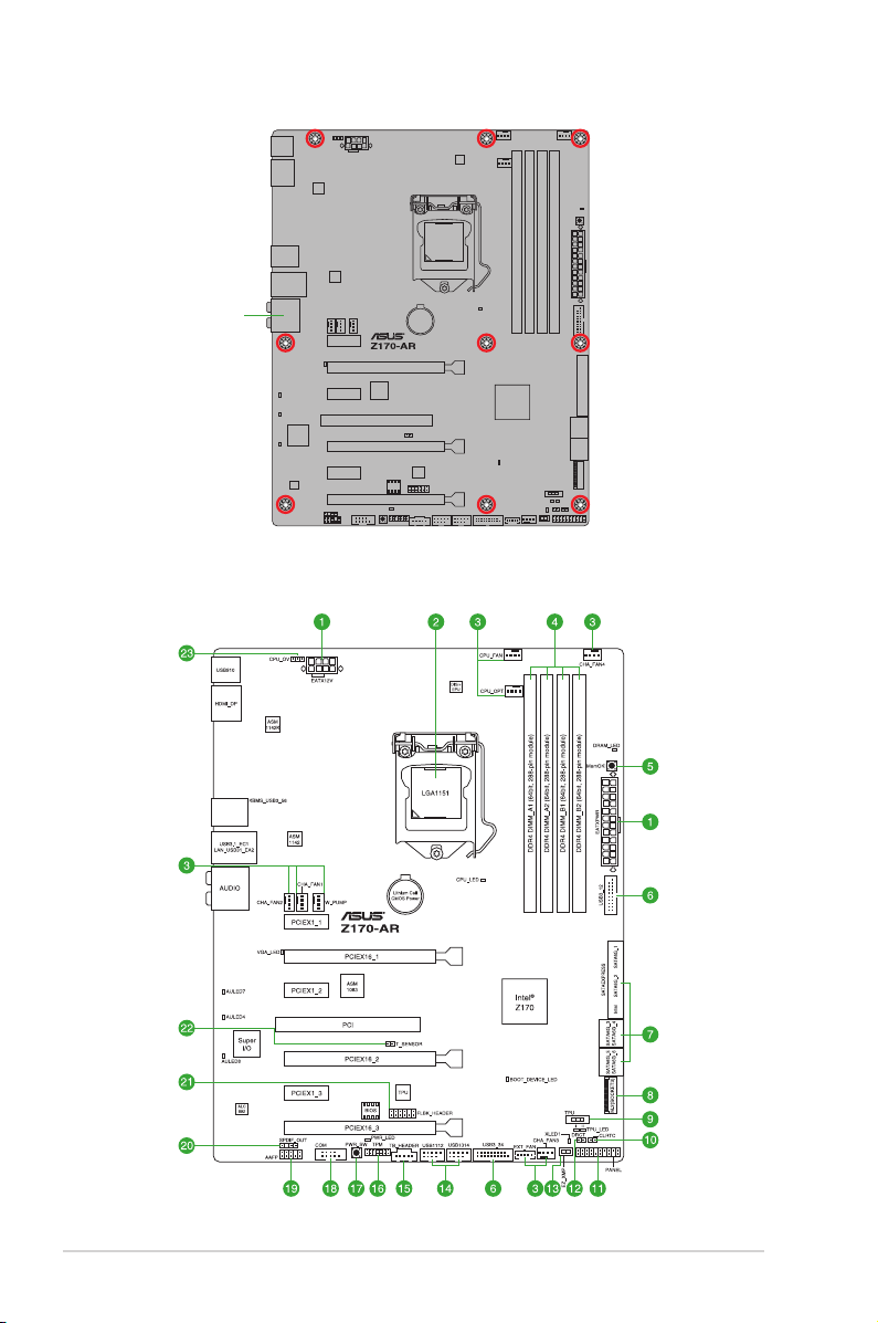
1.2.3 Motherboard layout
1-2
Chapter 1: Product Introduction
Page 15

1.2.4 Layout contents
Connectors/Jumpers/Slots/LED Page
1. ATX power connectors (24-pin EATXPWR, 8-pin EATX12V)
2. Intel® LGA1151 CPU socket 1-4
3. CPU, water pump, CPU optional, extension, and chassis fan connectors
(4-pin CPU_FAN; 3-pin W_PUMP; 4-pin CPU_OPT; 5-pin EXT_FAN; 4-pin
CHA_FAN1-4)
4. DDR4 DIMM slots 1-8
5. MemOK! button 1-36
6. USB 3.0 connectors (20-1 pin USB3_12, USB3_34)
7. Intel® Z170 Serial ATA 6.0 Gb/s connectors (7-pin SATA6G_12,
SATA6G_34, SATA6G_56, SATA Express)
8. M.2 Socket 3 1-28
9. TPU switch 1-37
10. Clear RTC RAM (2-pin CLRTC) 1-19
11. System panel connector (20-3 pin PANEL) 1-30
12. DirectKey connector (2-pin DRCT) 1-28
13. EZ XMP switch 1-38
14. USB 2.0 connectors (10-1 pin USB1112, USB1314) 1-29
15. Thunderbolt header (5-pin TB_HEADER) 1-32
16. TPM connector (14-1 pin TPM) 1-29
17. Power-on button 1-38
18. Serial port connector (10-1 pin COM) 1-23
19. Front panel audio connector (10-1 pin AAFP) 1-27
20. Digital audio connector (4-1 pin SPDIF_OUT) 1-27
21. Flashback header (12-1 pin FLBK_HEADER) 1-33
22. T_Sensor connector (2-pin T_SENSOR) 1-32
23. CPU Over Voltage jumper (3-pin CPU_OV) 1-20
1-26
1-25
1-31
1-24
ASUS Z170-AR Series
1-3
Page 16
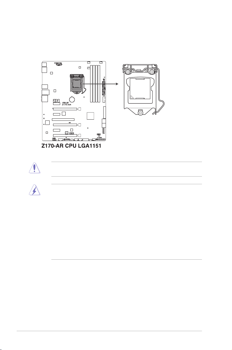
1.3 Central Processing Unit (CPU)
The motherboard comes with a surface mount LGA1151 socket designed for the 6th
Generation Intel® Core™ i7 / Intel® Core™ i5 / Intel® Core™ i3, Pentium®, and Celeron®
processors.
Ensure that you install the correct CPU designed for LGA1151 socket only. DO NOT install
a CPU designed for other sockets on the LGA1151 socket.
• Ensure that all power cables are unplugged before installing the CPU.
• Upon purchase of the motherboard, ensure that the PnP cap is on the socket and
the socket contacts are not bent. Contact your retailer immediately if the PnP cap
is missing, or if you see any damage to the PnP cap/socket contacts/motherboard
components. ASUS will shoulder the cost of repair only if the damage is shipment/
transit-related.
• Keep the cap after installing the motherboard. ASUS will process Return Merchandise
Authorization (RMA) requests only if the motherboard comes with the cap on the
LGA1150 socket.
• The product warranty does not cover damage to the socket contacts resulting from
incorrect CPU installation/removal, or misplacement/loss/incorrect removal of the PnP
cap.
1-4
Chapter 1: Product Introduction
Page 17
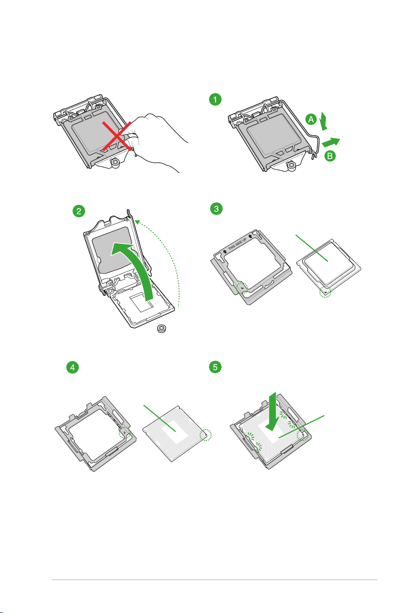
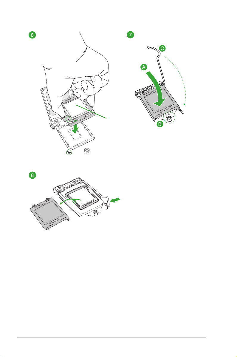
1.3.1 Installing the CPU
Top of CPU
Bottom of CPU
ASUS Z170-AR Series
Bottom of CPU
1-5
Page 18
Top of CPU
1-6
Chapter 1: Product Introduction
Page 19
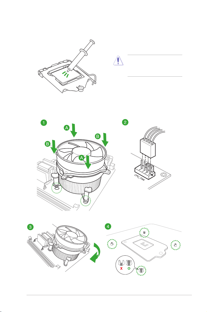
1.3.2 CPU heatsink and fan assembly installation
Apply the Thermal Interface Material
to the CPU heatsink and CPU
before you install the heatsink and
fan, if necessary.
To install the CPU heatsink and fan assembly
ASUS Z170-AR Series
1-7
Page 20
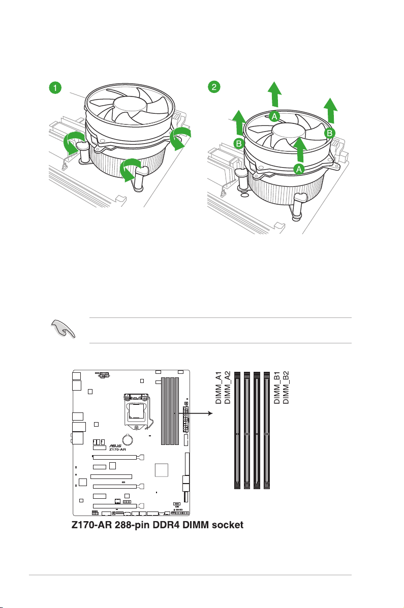
To uninstall the CPU heatsink and fan assembly
1.4 System memory
1.4.1 Overview
The motherboard comes with four Double Data Rate 4 (DDR4) Dual Inline Memory Modules
(DIMM) slots.
A DDR4 module is notched differently from a DDR, DDR2, or DDR3 module. DO NOT
install a DDR, DDR2, or DDR3 memory module to the DDR4 slot.
1-8
Chapter 1: Product Introduction
Page 21
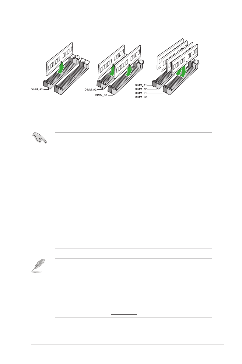
Recommended memory configurations
1.4.2 Memory configurations
You may install 1 GB, 2 GB, 4 GB, 8GB, and 16 GB unbuffered non-ECC DDR4 DIMMs into
the DIMM sockets. You can refer to the recommended memory population below.
• You may install varying memory sizes in Channel A and Channel B. The system
maps the total size of the lower-sized channel for the dual-channel conguration. Any
excess memory from the higher-sized channel is then mapped for single-channel
operation.
• Always install DIMMs with the same CAS latency. For optimal compatibility, we
recommend that you install memory modules of the same version or date code (D/C)
from the same vendor. Check with the retailer to get the correct memory modules.
• Due to the memory address limitation on 32-bit Windows® OS, when you install 4GB
or more memory on the motherboard, the actual usable memory for the OS can be
about 3GB or less. For effective use of memory, we recommend that you do any of the
following:
a) Use a maximum of 3GB system memory if you are using a 32-bit Windows® OS.
b) Install a 64-bit Windows® OS when you want to install 4 GB or more on the
motherboard.
c) For more details, refer to the Microsoft® support site at http://support.microsoft.
com/kb/929605/en-us.
• This motherboard does not support DIMMs made up of 512 Mb (64 MB) chips or less.
• The default memory operation frequency is dependent on its Serial Presence Detect
(SPD), which is the standard way of accessing information from a memory module.
Under the default state, some memory modules for overclocking may operate at a
lower frequency than the vendor-marked value. To operate at the vendor-marked
or at a higher frequency, refer to section 2.5 Ai Tweaker menu for manual memory
frequency adjustment.
• For system stability, use a more efcient memory cooling system to support a full
memory load (4 DIMMs).
• Visit the ASUS website at: www.asus.com for the latest QVL.
ASUS Z170-AR Series
1-9
Page 22

Z170-AR Motherboard Qualified Vendors Lists (QVL)
DDR4 3400 (O.C.) MHz capability
Vendors Part No. Size SS/DS Chip
CORSAIR CMD16GX4M4B3400C16
ver. 4.23
16GB(4GB*4) SS Samsung K4A4G085WD 16-18-18-38 1.35V •
Chip NO. Timing Voltage DIMM socket
Brand
support (Optional)
1 2 4
DDR4 3333 (O.C.) MHz capability
Vendors Part No. Size SS/DSChip
G.SKILL F4-3333C16D-8GTZ 8GB(4GB*2) SS SK Hynix H5AN4G8NMFR 16-18-18-38 1.35V •
G.SKILL F4-3333C16Q-16GRKD 16GB(4GB*4) SS Samsung K4A4G085WD 16-16-16-36 1.35V •
CORSAIR CMD16GX4M4B3333C16
ver4.23
A-DATA AX4U3333W4G16 16GB(4GB*4) SS SK Hynix H5AN4G8NMFR 16-16-16-36 1.35V •
16GB(4GB*4) SS Samsung K4A4G085WD 16-18-18-36 1.35V •
Chip NO. Timing Voltage DIMM socket
Brand
support (Optional)
1 2 4
DDR4 3300 (O.C.) MHz capability
Vendors Part No. Size SS/DSChip
G.SKILL F4-3300C16Q-16GRK 16GB(4GB*4) SS SK Hynix H5AN4G8NMFR 16-16-16-36 1.35V • •
G.SKILL F4-3300C16D-8GTZ 8GB(4GB*2) SS Samsung K4A4G085WD 16-18-18-38 1.35V • •
CORSAIR CMD16GX4M4B3300C16 16GB(4GB*4) SS Samsung K4A4G085WD 16-18-18-36 1.35V •
Chip NO. Timing Voltage DIMM socket
Brand
support (Optional)
1 2 4
DDR4 3200 (O.C.) MHz capability
Vendors Part No. Size SS/DSChip
G.SKILL F4-3200C16Q-16GRR 16GB(4GB*4) SS SK
G.SKILL F4-3200C16Q-16GRB 16GB(4GB*4) SS SK
G.SKILL F4-3200C16Q-16GRRK 16GB(4GB*4) SS SK
AVEXIR AVD4U32001604G-4BZ1 16GB(4GB*4) SS SK
AVEXIR AVD4U32001604G-4CIR 16GB(4GB*4) SS 16-18-18-36 1.35V •
CORSAIR CMD16GX4M4A3200C16 16GB(4GB*4) SS 16-18-18-36 1.35V •
GEIL GPR416GB3200C15QC 16GB(4GB*4) SS 15-15-15-35 1.35V •
Kingston HX432C16PB2K4/16 16GB(4GB*4) SS 16-16-16-39 1.35V •
Panram PUD43200C164G4NJW 16GB(4GB*4) SS 16-18-18-39 1.35V •
Chip NO. Timing Voltage DIMM socket
Brand
H5AN4G8NMFR 16-16-16-36 1.35V • •
Hynix
H5AN4G8NMFR 16-16-16-36 1.35V • •
Hynix
H5AN4G8NMFR 16-16-16-36 1.35V • •
Hynix
H5AN4G8NMFR 16-18-18-36 1.35V •
Hynix
support (Optional)
1 2 4
1-10
Chapter 1: Product Introduction
Page 23

DDR4 3000 (O.C.) MHz capability
Vendors Part No. Size SS/DSChip
G.SKILL F4-3000C15Q-32GRR 32GB(8GB*4) DS SK Hynix H5AN4G8NMFR 15-15-15-35 1.35V •
G.SKILL F4-3000C15Q-32GRB 32GB(8GB*4) DS SK Hynix H5AN4G8NMFR 15-15-15-35 1.35V •
G.SKILL F4-3000C15Q-32GRK 32GB(8GB*4) DS SK Hynix H5AN4G8NMFR 15-15-15-35 1.35V •
G.SKILL F4-3000C16Q-32GRR 32GB(8GB*4) DS SK Hynix H5AN4G8NMFR 16-16-16-36 1.35V •
G.SKILL F4-3000C16Q-32GRB 32GB(8GB*4) DS SK Hynix H5AN4G8NMFR 16-16-16-36 1.35V •
G.SKILL F4-3000C16Q-32GRK 32GB(8GB*4) DS SK Hynix H5AN4G8NMFR 16-16-16-36 1.35V •
G.SKILL F4-3000C15Q-16GRR 16GB(4GB*4) SS SK Hynix H5AN4G8NMFR 15-15-15-35 1.35V • •
G.SKILL F4-3000C15Q-16GRB 16GB(4GB*4) SS SK Hynix H5AN4G8NMFR 15-15-15-35 1.35V • •
G.SKILL F4-3000C15Q-16GRK 16GB(4GB*4) SS SK Hynix H5AN4G8NMFR 15-15-15-35 1.35V • •
G.SKILL F4-3000C15Q2-32GRK 32GB(4GB*8) SS SK Hynix H5AN4G8NMFR 15-15-15-35 1.35V • •
G.SKILL F4-3000C15D-8GTZ 8GB(4GB*2) SS Samsung K4A4G085WD 15-15-15-35 1.35V • •
AVEXIR AVD4U30001604G-4CI 16GB(4GB*4) SS SK Hynix H5AN4G8NMFR 16-18-18-36 1.35V • •
AVEXIR AVD4U30001504G-4BZ1 16GB(4GB*4) SS SK Hynix H5AN4G8NMFR 15-15-15-35 1.35V • •
AVEXIR AVD4U30001608G-4CI 32GB(8GB*4) DS SK Hynix H5AN4G8NMFR 16-18-18-36 1.35V •
Kingston HX430C15PB2K4/16 16GB(4GB*4) SS 15-16-16-39 1.35V • •
CORSAIR CMD16GX4M4B3000C15 16GB(4GB*4) SS Samsung K4A4G085WD 15-17-17-35 1.35V • •
CORSAIR CMK16GX4M4B3000C15 16GB(4GB*4) SS Samsung K4A4G085WD 15-17-17-35 1.35V • •
Panram PUD43000C154G4NJW 16GB(4GB*4) SS 15-17-17-35 1.35V • •
Asint SLB404G08-EWWHMX 16GB(8GB*2) SS SK Hynix H5AN4G8NMFR 15-15-15-44 1.35V •
Chip NO. Timing Voltage DIMM socket
Brand
support
(Optional)
1 2 4
DDR4 2800 (O.C.) MHz capability
Vendors Part No. Size SS/DS Chip
ADATA AX4U2800W4G17 32GB(4GB*8) DS - - 17-17-17-36 1.2 • • •
ADATA AX4U2800W8G17 8GB DS - - 15-15-15-36 1.2 • • •
Apacer 78.BAGM8.AF20B(XMP) 4GB SS - - 17-17-17-36 - • • •
Apacer 78.CAGM8.AF30B(XMP) 8GB DS - - 17-17-17-36 - • • •
AVEXIR AVD4U28001504G-4CIR(XMP) 4GB SS - - 15-15-15-35 1.35 • • •
AVEXIR AVD4U28001608G-4CIR(XMP) 32GB(4GB*8) DS - - 16-16-16-36 1.2 • •
CORSAIR CMD16GX4M4A2800C16(Ver4.23)
(XMP)
CORSAIR CMD16GX4M4A2800C16(Ver5.29) 16GB(4GB*4) SS - - 16-18-18-36 1.2 • • •
CORSAIR CMD32GX4M4A2800C16(Ver5.29)
(XMP)
CORSAIR CMK16GX4M4A2800C16(Ver4.23)
(XMP)
16GB(4GB*4) SS - - 16-18-18-36 1.2 • • •
32GB(8GB*4) DS - - 18-18-18-36 1.2 • • •
16GB(4GB*4) SS - - 16-16-18-36 1.2 • • •
(continued on the next page)
Brand
Chip
Timing Voltage DIMM socket
NO.
support (Optional)
1 2 4
ASUS Z170-AR Series
1-11
Page 24

DDR4 2800 (O.C.) MHz capability
Vendors Part No. Size SS/DS Chip
CORSAIR CMK16GX4M4A2800C16(Ver5.29) 16GB(4GB*4) SS - - 16-18-18-36 1.2 • • •
CORSAIR CMK32GX4M4A2800C16(Ver5.29)
(XMP)
G.SKILL F4-2800C15Q2-64GRK(XMP) 64GB(8GB*8) DS - - 15-16-16-35 1.25 • • •
G.SKILL F4-2800C16Q-16GRR(XMP) 16GB(4GB*4) SS - - 16-16-16-36 1.2 • • •
G.SKILL F4-2800C16Q-32GRR(XMP) 32GB(8GB*4) DS - - 16-16-16-36 1.2 • • •
Kingston HX428C14PBK4/16(XMP) 16GB(4GB*4) SS - - 14-15-15-40 1.35 • • •
Panram PUD42800C164G4NJW(XMP) 16GB(4GB*4) SS - - 16-18-18-36 1.25 • • •
32GB(8GB*4) DS - - 16-18-18-36 1.2 • • •
Brand
Chip
Timing Voltage DIMM socket
NO.
support (Optional)
1 2 4
DDR4 2666 (O.C.) MHz capability
Vendors Part No. Size SS/DS Chip
AVEXIR AVD4U26661504G-4CIR(XMP) 4GB SS - - 15-15-15-35 1.2 • • •
AVEXIR AVD4U26661608G-4CIR(XMP) 32GB
CORSAIR CMD128GX4M8A2666C15(Ver4.31)
(XMP)
CORSAIR CMD16GX4M4A2666C15(Ver4.23)
(XMP)
CORSAIR CMD16GX4M4A2666C16(Ver4.23)
(XMP)
CORSAIR CMD16GX4M4A2666C16(Ver5.29)
(XMP)
CORSAIR CMD32GX4M4A2666C15(Ver4.23)
(XMP)
CORSAIR CMD32GX4M4A2666C15(Ver5.29) 32G
CORSAIR CMD32GX4M4A2666C16(Ver4.23)
(XMP)
CORSAIR CMK16GX4M4A2666C15(Ver4.23)
(XMP)
CORSAIR CMK16GX4M4A2666C15(Ver5.29) 16GB
CORSAIR CMK16GX4M4A2666C16(Ver4.23)
(XMP)
CORSAIR CMK16GX4M4A2666C16(Ver5.29)
(XMP)
CORSAIR CMK32GX4M4A2666C15(Ver4.23)
(XMP)
CORSAIR CMK32GX4M4A2666C15(Ver5.29)
(XMP)
CORSAIR CMK32GX4M4A2666C16(Ver5.29)
(XMP)
CORSAIR CMK32GX4M4A2666C16R(Ver4.23)
(XMP)
G.SKILL F4-2666C15Q-16GRR(XMP) 16GB
G.SKILL F4-2666C15Q-32GRR(XMP) 32GB
DS - - 16-16-16-36 1.2 • • •
(4GB*8)
128GB
DS - - 15-17-17-35 1.2 • • •
(8GB*16)
16GB
SS - - 15-17-17-35 1.2 • • •
(4GB*4)
16GB
SS - - 16-18-18-35 1.2 • • •
(4GB*4)
16GB
SS - - 16-18-18-35 1.2 • • •
(4GB*4)
32GB
DS - - 15-17-17-35 1.2 • • •
(8GB*4)
DS - - 15-17-17-35 1.2 • • •
(8GB*4)
32GB
DS - - 16-18-18-35 1.2 • • •
(8GB*4)
16GB
SS - - 15-17-17-35 1.2 • • •
(4GB*4)
SS - - 15-17-17-35 1.2 • • •
(4GB*4)
16GB
SS - - 16-18-18-35 1.2 • • •
(4GB*4)
16GB
SS - - 16-18-18-35 1.2 • • •
(4GB*4)
32GB
DS - - 15-17-17-35 1.2 • • •
(8GB*4)
32GB
DS - - 15-17-17-35 1.2 • • •
(8GB*4)
32GB
DS - - 16-16-18-35 1.2 • • •
(8GB*4)
32GB
DS - - 16-18-18-35 1.2 • • •
(8GB*4)
SS - - 15-15-15-35 1.2 • • •
(4GB*4)
DS - - 15-15-15-35 1.2 • • •
(8GB*4)
(continued on the next page)
Chip NO. Timing Voltage DIMM socket
Brand
support
(Optional)
1 2 4
1-12
Chapter 1: Product Introduction
Page 25

DDR4 2666 (O.C.) MHz capability
Vendors Part No. Size SS/DS Chip
G.SKILL F4-2666C16Q2-64GRB
(XMP)
ISDT IMA41GU6MFR8N-CF0
(XMP)
ISDT IMA451U6MFR8N-CF0
(XMP)
Team TCD44G2666C15ABK(XMP) 4GB SS Samsung K4A4G085WD 15-15-15-35 1.2 • • •
Team TCD48G2666C15ABK(XMP) 32GB
64GB
DS - - 16-16-16-36 1.2 • • •
(8GB*8)
8GB DS ISDT I5AN4G8NMFR 15-15-15-35 1.2 • • •
4GB SS ISDT I5AN4G8NMFR 15-15-15-35 1.2 • • •
DS Team TCD48G2666C15ABK 15-15-15-35 1.2 • • •
(8GB*4)
Chip NO. Timing Voltage DIMM socket
Brand
support
(Optional)
1 2 4
DDR4 2400 (O.C.) MHz capability
Vendors Part No. Size SS/DS Chip
AVEXIR AVD4U24001604G-4CIR
(XMP)
AVEXIR AVD4U24001608G-4M 32GB
AVEXIR AVD4U24001608G-4M
(XMP)
CORSAIR CMD16GX4M4A2400C14
(Ver4.23)(XMP)
CORSAIR CMD32GX4M4A2400C14
(Ver4.23)(XMP)
CORSAIR CMK16GX4M4A2400C14
(Ver4.23)(XMP)
CORSAIR CMK32GX4M4A2400C14
(Ver4.23)(XMP)
Crucial BLS4G4D240FSA.8FAD 4GB SS - - 16-16-16-40 1.2 • • •
Crucial BLS4G4D240FSA.8FAR
(XMP)
Crucial BLS8G4D240FSA.16FAD 8GB DS - - 16-16-16-40 1.2 • • •
Crucial BLS8G4D240FSA.16FAR
(XMP)
G.SKILL F4-2400C15Q-16GRR 16GB
G.SKILL F4-2400C15Q2-128GRK
(XMP)
G.SKILL F4-2400C15Q-32GRR 32GB
Kingston HX424C12PB2K4/16 16GB
Panram PUD42400C154G4NJW 16GB
Panram PUD42400C158G4NJW 32GB
Team TED44GM2400C16BK 4GB SS Samsung K4A4G085WD 16-16-16-39 1.2 • • •
Team TED48GM2400C16BK 8GB DS Samsung K4A4G085WD 16-16-16-39 1.2 • • •
V-color TD4G8C17-UH 4GB SS V-color DW3J0460HM 15-15-15-36 1.2 • • •
4GB SS - - 16-16-16-36 1.2 • • •
DS SK Hynix H5AN4G8NMFRTFC 16-16-16-39 1.2 • • •
(4GB*8)
32GB
DS SK Hynix H5AN4G8NMFRTFC 16-16-16-36 1.2 • • •
(4GB*8)
16GB
SS - - 14-16-16-31 1.2 • • •
(4GB*4)
32GB
DS - - 14-16-16-31 1.2 • • •
(8GB*4)
16GB
SS - - 14-16-16-31 1.2 • • •
(4GB*4)
32GB
DS - - 14-16-16-31 1.2 • • •
(8GB*4)
4GB SS - - 17-16-16-39 1.2 • • •
8GB DS - - 17-16-16-39 1.2 • • •
SS - - 15-15-15-35 1.2 • • •
(4GB*4)
128GB
DS - - 15-15-15-35 1.2 • • •
(16GB*8)
DS - - 15-15-15-35 1.2 • • •
(8GB*4)
SS - - 15-15-15-36 1.2 • • •
(4GB*4)
SS - - 15-15-15-35 1.2 • • •
(4GB*4)
DS - - 15-15-15-35 1.2 • • •
(8GB*4)
Chip NO. Timing Voltage DIMM socket
Brand
support
(Optional)
1 2 4
ASUS Z170-AR Series
1-13
Page 26

DDR4 2133 MHz capability
Vendors Part No. Size SS/DS Chip
ADATA AD4U2133W4G15-B 4GB SS SK Hynix H5AN4G8NMFRTFC 15-15-15-36 - • • •
ADATA AD4U2133W8G15 8GB DS SK Hynix H5AN4G8NMFRTFC 15-15-15-36 1.2 • • •
Apacer 78.B1GM3.AF00B 4GB SS SK Hynix H5AN4G8NMFRTFC 15-15-15-36 1.2 • • •
Apacer 78.C1GM3.AF10B 8GB DS SK Hynix H5AN4G8NMFRTFC 15-15-15-36 1.2 • • •
AVEXIR AVD4U21331504G-4M 4GB SS AVEXIR 512X8DDR4 15-15-15-35 1.2 • • •
Century CD8G-D4U2133 8GB DS SK Hynix H5AN4G8NMFRTFC 15-15-15-36 - • • •
CORSAIR CMK16GX4M4A2133C13
(Ver4.23)(XMP)
CORSAIR CMK32GX4M4A2133C13
(Ver4.23)(XMP)
CORSAIR CMK64GX4M8A2133C13
(Ver4.23)(XMP)
CORSAIR CMV4GX4M1A2133C15 4GB SS - - 15-15-15-36 1.2 • • •
CORSAIR CMV8GX4M1A2133C15 8GB DS - - 15-15-15-36 1.2 • • •
G.SKILL F4-2133C15Q-16GRR 16GB
G.SKILL F4-2133C15Q-32GRR 32GB
ISDT IMA41GU6MFR8N-TF0 8GB DS ISDT I5AN4G8NMFR 15-15-15-35 1.2 • • •
ISDT IMA451U6MFR8N-TF0 4GB SS ISDT I5AN4G8NMFR 15-15-15-35 1.2 • • •
Panram PUD42133C134G4NJW 16GB
Panram PUD42133C138G4NJW 32GB
Panram PUD42133C154G2VS 8GB
Panram PUD42133C154GNJK 4GB SS - - 15-15-15-36 1.2 • • •
Panram PUD42133C158G2VS 16GB
Panram PUD42133C158GNJK 8GB DS - - 15-15-15-36 1.2 • • •
Samsung M378A1G43DB0-CPB 8GB DS Samsung K4A4G085WD 15-15-15-36 - • • •
SanMax SMD-4G28HP-21P 4GB SS SK Hynix H5AN4G8NMFRTFC 15-15-15-37 - • • •
SanMax SMD-8G28HP-21P 8GB DS SK Hynix H5AN4G8NMFRTFC 15-15-15-37 - • • •
SK Hynix HMA82GU6MFR8N-TF 16GB DS SK Hynix H5AN8G8NMFRTFC 15-15-15-36 - • • •
SUPER
FBU2B008GM 8GB DS Micron D9RGQ 15-15-15-36 1.2 • • •
TALENT
Team TED44GM2133C15ABK 4GB SS SK Hynix H5AN4G8NMFRTFC 15-15-15-36 1.2 • • •
Transcend TS1GLH64V1H 8GB DS Samsung K4A4G085WD 15-15-15-37 - • • •
Transcend TS512MLH64V1H 4GB SS Samsung K4A4G085WD 15-15-15-37 - • • •
UMAX 84G44G93MC-
21OMCALGF15
UMAX 84G48G93MC-
21OMCGNGF15
16GB
SS - - 13-15-15-28 1.2 • • •
(4GB*4)
32GB
DS - - 13-15-15-28 1.2 • • •
(8GB*4)
64GB
DS - - 13-15-15-28 1.2 • • •
(8GB*8)
SS - - 15-15-15-35 1.2 • • •
(4GB*4)
DS - - 15-15-15-35 - • • •
(8GB*4)
SS - - 13-13-13-35 1.2 • • •
(4GB*4)
DS - - 13-13-13-35 1.2 • • •
(8GB*4)
SS SK Hynix H5AN4GBNMFRTFC 15-15-15-36 1.2 • • •
(4GB*2)
DS SK Hynix H5AN4GBNMFRTFC 15-15-15-36 1.2 • • •
(8GB*2)
4GB SS Micron D9RGQ 15-15-15-36 - • • •
8GB DS Micron D9RGQ 15-15-15-36 - • • •
Chip NO. Timing Voltage DIMM socket
Brand
support
(Optional)
1 2 4
1-14
Chapter 1: Product Introduction
Page 27
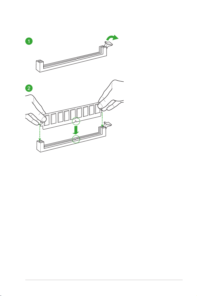
1.4.3 DIMM installation
ASUS Z170-AR Series
1-15
Page 28
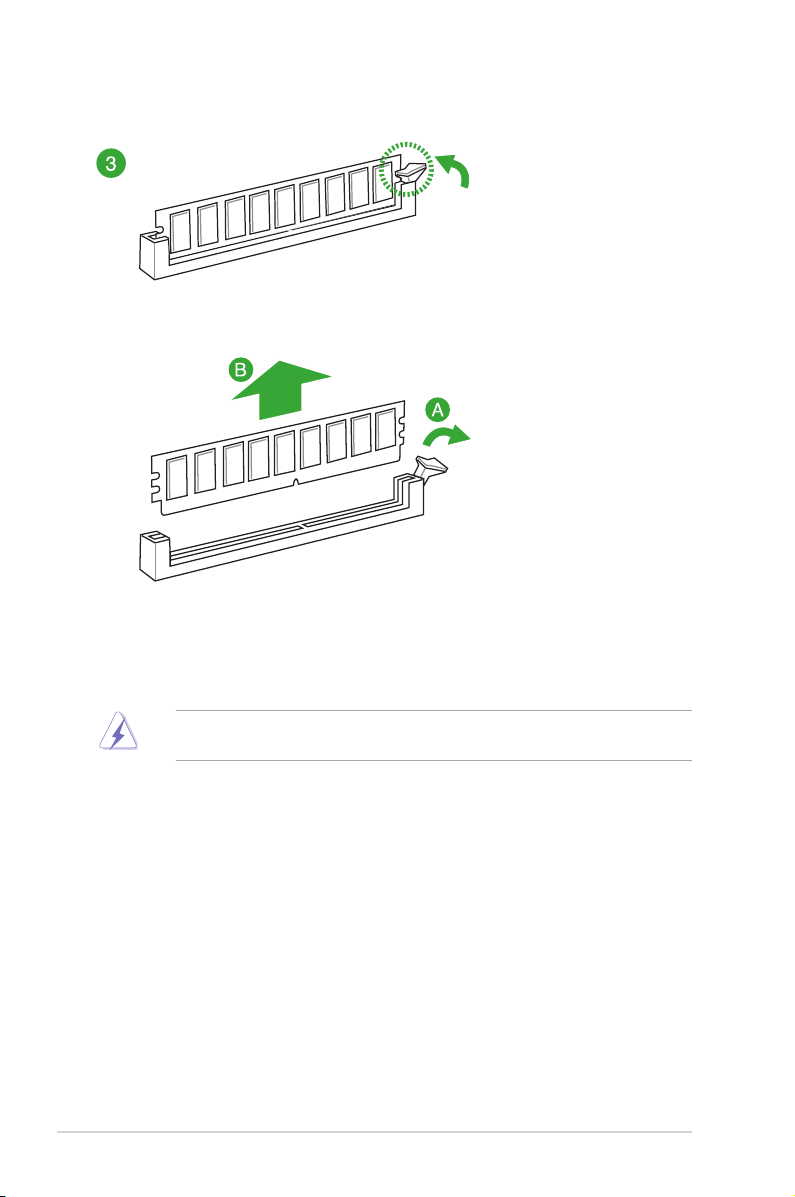
To remove a DIMM
1.5 Expansion slots
In the future, you may need to install expansion cards. The following sub-sections describe
the slots and the expansion cards that they support.
Unplug the power cord before adding or removing expansion cards. Failure to do so may
cause you physical injury and damage motherboard components.
1.5.1 Installing an expansion card
To install an expansion card:
1. Before installing the expansion card, read the documentation that came with it and
make the necessary hardware settings for the card.
2. Remove the system unit cover (if your motherboard is already installed in a chassis).
3. Remove the bracket opposite the slot that you intend to use. Keep the screw for later
use.
4. Align the card connector with the slot and press rmly until the card is completely
seated on the slot.
5. Secure the card to the chassis with the screw you removed earlier.
6. Replace the system cover.
1-16
Chapter 1: Product Introduction
Page 29
1.5.2 Configuring an expansion card
After installing the expansion card, congure it by adjusting the software settings:
1. Turn on the system and change the necessary BIOS settings, if any. See Chapter 2 for
information on BIOS setup.
2. Assign an IRQ to the card.
3. Install the software drivers for the expansion card.
When using PCI cards on shared slots, ensure that the drivers support “Share IRQ” or that
the cards do not need IRQ assignments. Otherwise, conicts arise between the two PCI
groups, making the system unstable and the card inoperable.
1.5.3 PCI slot
The PCI slot supports cards such as a LAN card, SCSI card, USB card, and other cards that
comply with PCI specications.
1.5.4 PCI Express 3.0 / 2.0 x1 slots
This motherboard supports PCI Express x1 network cards, SCSI cards, and other cards that
comply with the PCI Express specications.
1.5.5 PCI Express 3.0 / 2.0 x16 slots
This motherboard supports PCI Express x16 network cards, SCSI cards, and other cards that
comply with the PCI Express specications.
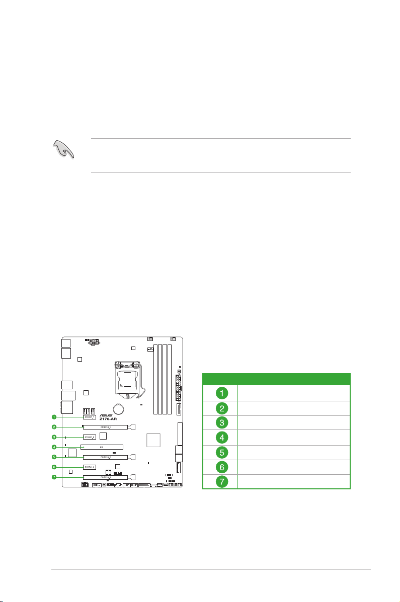
ASUS Z170-AR Series
Slot No. Expansion slot
PCIe 3.0/2.0 x1_1 slot
PCIe 3.0/2.0 x16_1 slot
PCIe 3.0/2.0 x1_2 slot
PCI slot
PCIe 3.0/2.0 x16_2 slot
PCIe 3.0/2.0 x1_3 slot
PCIe 3.0/2.0 x16_3 slot
1-17
Page 30

VGA configuration
PCI Express 3.0 operating mode
PCIe 3.0/2.0 x16_1 PCIe 3.0/2.0 x16_2
Single VGA/PCIe card
Dual VGA/PCIe card x8 x8
• We recommend that you provide sufcient power when running CrossFireX™ or SLI™
mode.
• Connect a chassis fan to the motherboard connector labeled CHA_FAN1-4 when
using multiple graphics cards for better thermal environment.
x16 (single VGA
recommended)
IRQ assignments for this motherboard
A B
PCIE x16_1 Shared – – –
PCIE x16_2 Shared – – –
PCIE x16_3 Shared – – –
PCIE x1_1 – Shared – –
PCIE x1_2 – – Shared –
PCIE x1_3 – – – Shared
SMBUS Controller Shared – – –
Intel SATA Controller Shared – – –
Intel LAN Shared – – –
Intel xHCI Shared – – –
HD Audio Shared – – –
ASMedia Controller Shared – – –
PCI Slot – – Shared –
D
C
N/A
1-18
Chapter 1: Product Introduction
Page 31

1.6 Jumpers
1. Clear RTC RAM (2-pin CLRTC)
This jumper allows you to clear the Real Time Clock (RTC) RAM in CMOS. You can
clear the CMOS memory of date, time, and system setup parameters by erasing the
CMOS RTC RAM data. The onboard button cell battery powers the RAM data in
CMOS, which include system setup information such as system passwords.
To erase the RTC RAM:
1. Turn OFF the computer and unplug the power cord.
2. Short-circuit pin 1-2 with a metal object or jumper cap for about 5-10 seconds.
3. Plug the power cord and turn ON the computer.
4. Hold down the <Del> key during the boot process and enter BIOS setup to re-
enter data.
Except when clearing the RTC RAM, never short-circuit the CLRTC jumper. Shorting the
CLRTC jumper will cause system boot failure!
• If the steps above do not help, remove the onboard battery and move the jumper
again to clear the CMOS RTC RAM data. After clearing the CMOS, reinstall the
battery.
• You do not need to clear the RTC when thae system hangs due to overclocking. For
system failure due to overclocking, use the CPU Parameter Recall (C.P.R.) feature.
Shut down and reboot the system, then the BIOS automatically resets parameter
settings to default values.
• Due to chipset behavior, AC power off is required to enable C.P.R. function. You must
turn off and on the power supply or unplug and plug the power cord before rebooting
the system.
ASUS Z170-AR Series
1-19
Page 32

2. CPU Over Voltage jumper (3-pin CPU_OV)
The CPU Over Voltage jumper allows you to set a higher CPU voltage for a exible
overclocking system, depending on the type of the installed CPU. To gain more CPU
voltage setting, insert the jumper to pins 2-3. To go back to its default CPU voltage
setting, insert the jumper to pins 1-2.
1-20
Chapter 1: Product Introduction
Page 33

1.7 Connectors
1.7.1 Rear panel connectors
Rear panel connectors
1. USB 2.0 ports 910 6.
2. DisplayPort 7.
3. PS/2 keyboard/mouse port 8.
4. LAN port* 9. Optical S/PDIF Out port
5. HDMI port 10. Audio I/O ports**
* and **: Refer to the tables on the next page for LAN port LEDs and audio port definitions.
ASUS Z170-AR Series
USB 3.0 ports 56 (supports USB 3.1
Boost)
USB Type-C port EC1 (supports USB
3.1 Boost)
LAN_USB31_EA2 (supports USB 3.1
Boost)
1-21
Page 34

• The plugged USB 3.0 device will run on xHCI mode.
• USB 3.0 devices can only be used for data storage.
• We strongly recommend that you connect USB 3.0 devices to USB 3.0 ports for faster
and better performance from your USB 3.0 devices.
• Due to the design of the Intel® chipset, all USB devices connected to the USB 2.0 and
USB 3.0 ports are controlled by the xHCI controller. Some legacy USB devices must
update their rmware for better compatibility.
• Multi-VGA output supports up to three displays under Windows® OS environment, two
displays under BIOS, and one display under DOS.
• Intel display architecture design supports the following maximum supported pixel
clocks (Pixel Clock = H total x V Total x Frame Rate (Screen refresh rate)):
- DVI port: 148 MHz
- DisplayPort: 675 MHz
- VGA port: 210 MHz
- HDMI port: 300 MHz
* LAN ports LED indications
Activity Link LED Speed LED
Status Description Status Description
Off
Orange
Orange (Blinking)
Orange (Blinking
then steady)
No link Off 10 Mbps connection
Linked Orange 100 Mbps connection
Data activity Green 1 Gbps connection
Ready to wake up
from S5 mode
ACT/LINK
LED
LAN port
SPEED
LED
**Audio 2, 4, 6, or 8-channel configuration
Port
Headset
2-channel
4-channel 6-channel 8-channel
Light Blue Line In Line In Line In Side Speaker Out
Lime Line Out Front Speaker Out Front Speaker Out Front Speaker Out
Pink Mic In Mic In Mic In Mic In
Orange – – Center/Subwoofer Center/Subwoofer
Black – Rear Speaker Out Rear Speaker Out Rear Speaker Out
1-22
Chapter 1: Product Introduction
Page 35

1.7.2 Internal connectors
1. Serial port connector (10-1 pin COM)
This connector is for a serial (COM) port. Connect the serial port module cable to this
connector, then install the module to a slot opening at the back of the system chassis.
The COM module is purchased separately.
ASUS Z170-AR Series
1-23
Page 36

2. Intel® Z170 Serial ATA 6.0 Gb/s connectors (7-pin SATA6G_12, SATA6G_34,
SATA6G_56, SATA Express)
These connectors connect to Serial ATA 6 Gb/s hard disk drives via Serial ATA 6 Gb/s
signal cables.
If you installed Serial ATA hard disk drives, you can create a RAID 0, 1, 5, and 10
conguration with the Intel® Rapid Storage Technology through the onboard Intel
®
Z170 chipset.
These connectors are set to [AHCI Mode] by default. If you intend to create a Serial ATA
RAID set using these connectors, set the SATA Mode item in the BIOS to [RAID Mode].
Refer to section 2.6.5 PCH Storage Configuration for details.
• The M.2 socket shares SATA ports with SATA Express. Only one SATA device could
be activated. To use an M.2 SATA device, refer to section 2.6.8 Onboard Devices
Configuration regarding the BIOS switch.
• The SATAEXPRESS connector can support one SATA Express device or two SATA
devices.
1-24
Chapter 1: Product Introduction
Page 37

3. CPU, water pump, CPU optional, extension, and chassis fan connectors (4-pin
CPU_FAN; 3-pin W_PUMP; 4-pin CPU_OPT; 5-pin EXT_FAN; 4-pin CHA_FAN1-4)
Connect the fan cables to the fan connectors on the motherboard, ensuring that the
black wire of each cable matches the ground pin of the connector.
• DO NOT forget to connect the fan cables to the fan connectors. Insufcient air ow
inside the system may damage the motherboard components. These are not jumpers!
Do not place jumper caps on the fan connectors! The CPU_FAN connector supports a
CPU fan of maximum 1 A (12 W) fan power.
• Ensure that the CPU fan cable is securely installed to the CPU fan connector.
• The CPU_FAN connector supports the CPU fan of maximum 1A (12 W) fan power.
• W_PUMP function support depends on water cooling device.
• The CPU_FAN connector and CHA_FAN connectors support the ASUS FAN Xpert 3
feature.
• The CPU fan connector detects the type of CPU fan installed and automatically
switches the control modes. To congure the CPU fan’s control mode, go to
Advanced Mode > Monitor > CPU Q-Fan Control item in BIOS.
• The chassis fan connectors support DC and PWM modes. To set these fans to DC or
PWM, go to Advanced Mode > Monitor > Chassis Fan 1/4 Q-Fan Control items in
BIOS.
The FAN EXTENSION CARD is purchased separately.
ASUS Z170-AR Series
1-25
Page 38

4. ATX power connectors (24-pin EATXPWR, 8-pin EATX12V)
These connectors are for ATX power supply plugs. The power supply plugs are
designed to t these connectors in only one orientation. Find the proper orientation and
push down rmly until the connectors completely t.
• For a fully congured system, we recommend that you use a power supply unit
(PSU) that complies with ATX 12 V Specication 2.0 (or later version) and provides a
minimum power of 350 W.
• DO NOT forget to connect the 4-pin/8-pin ATX +12V power plug. Otherwise, the
system will not boot up.
• We recommend that you use a PSU with higher power output when conguring a
system with more power-consuming devices or when you intend to install additional
devices. The system may become unstable or may not boot up if the power is
inadequate.
• If you want to use two or more high-end PCI Express x16 cards, use a PSU with
1000W power or above to ensure the system stability.
• If you are uncertain about the minimum power supply requirement for your system,
refer to the Recommended Power Supply Wattage Calculator at http://support.asus.
com/PowerSupplyCalculator/PSCalculator.aspx?SLanguage=en-us for details.
1-26
Chapter 1: Product Introduction
Page 39

5. Front panel audio connector (10-1 pin AAFP)
This connector is for a chassis-mounted front panel audio I/O module that supports
either HD Audio or legacy AC`97 audio standard. Connect one end of the front panel
audio I/O module cable to this connector.
• We recommend that you connect a high-denition front panel audio module to this
connector to avail of the motherboard’s high-denition audio capability.
• If you want to connect a high-denition front panel audio module to this connector,
set the Front Panel Type item in the BIOS setup to [HD Audio]. If you want to connect
an AC’97 front panel audio module to this connector, set the item to [AC97]. By
default, this connector is set to [HD Audio]. See section 2.6.8 Onboard Devices
Configuration for details.
6. Digital audio connector (4-1 pin SPDIF_OUT)
This connector is for an additional Sony/Philips Digital Interface (S/PDIF) port. Connect
the S/PDIF Out module cable to this connector, then install the module to a slot
opening at the back of the system chassis.
The S/PDIF module is purchased separately.
ASUS Z170-AR Series
1-27
Page 40

7. DirectKey connector (2-pin DRCT)
This connector is for the chassis-mounted button that supports the DirectKey function.
Connect the button cable that supports DirectKey, from the chassis to this connector
on the motherboard.
Ensure that your chassis comes with the extra button cable that supports the DirectKey
feature. Refer to the technical documentation that came with the chassis for details.
8. M.2 socket 3
This socket allows you to install an M.2 (NGFF) SSD module.
1-28
• This socket supports M Key and type 2242/2260/2280/22110 storage devices.
• The M.2 (NGFF) SSD module is purchased separately.
• The M.2 shares SATA mode with SATA Express. Change this item before installing
M.2 SATA devices.
Chapter 1: Product Introduction
Page 41

9. USB 2.0 connectors (10-1 pin USB1112, USB1314)
These connectors are for USB 2.0 ports. Connect the USB module cable to any of
these connectors, then install the module to a slot opening at the back of the system
chassis. These USB connectors comply with USB 2.0 specications and supports up to
480 Mb/s connection speed.
Never connect a 1394 cable to the USB connectors. Doing so will damage the
motherboard!
The USB 2.0 module is purchased separately.
These connectors are based on xHCI specication. We recommend you to install the
related driver to fully use the USB 2.0 ports under Windows® 7.
10. TPM connector (14-1 pin TPM)
This connector supports a Trusted Platform Module (TPM) system, which securely
store keys, digital certicates, passwords and data. A TPM system also helps enhance
network security, protects digital identities, and ensures platform integrity.
ASUS Z170-AR Series
1-29
Page 42

11. System panel connector (20-3 pin PANEL)
This connector supports several chassis-mounted functions.
• SystempowerLED(2-pinor3-pinPWR_LED)
The 2-pin or 3-pin connector is for the system power LED. Connect the chassis power
LED cable to this connector. The system power LED lights up when you turn on the
system power, and blinks when the system is in sleep mode.
• HarddiskdriveactivityLED(2-pinHDD_LED)
This 2-pin connector is for the HDD Activity LED. Connect the HDD Activity LED cable
to this connector. The HDD LED lights up or ashes when data is read from or written
to the HDD.
• Systemwarningspeaker(4-pinSPEAKER)
This 4-pin connector is for the chassis-mounted system warning speaker. The speaker
allows you to hear system beeps and warnings.
• ATXpowerbutton/soft-offbutton(2-pinPWR_SW)
This connector is for the system power button. Pressing the power button turns the
system on or puts the system in sleep or soft-off mode depending on the operating
system settings. Pressing the power switch for more than four seconds while the
system is ON turns the system OFF.
• Resetbutton(2-pinRESET)
This 2-pin connector is for the chassis-mounted reset button for system reboot without
turning off the system power.
1-30
Chapter 1: Product Introduction
Page 43

12. USB 3.0 connectors (20-1 pin USB3_12, USB3_34)
This connector allows you to connect a USB 3.0 module for additional USB 3.0 front
or rear panel ports. With an installed USB 3.0 module, you can enjoy all the benets of
USB 3.0 including faster data transfer speeds of up to 5 Gb/s, faster charging time for
USB-chargeable devices, optimized power efciency, and backward compatibility with
USB 2.0.
The USB 3.0 module is purchased separately.
• These connectors are based on xHCI specication. We recommend you to install the
related driver to fully use the USB 3.0 ports under Windows® 7.
• The plugged USB 3.0 device will run on xHCI mode.
• These USB 3.0 ports support native UASP transfer standard in Windows® 8 /
Windows® 8.1 and Turbo Mode when using USB 3.0 Boost feature.
ASUS Z170-AR Series
1-31
Page 44

13. Thunderbolt header (5-pin TB_HEADER)
This connector is for the add-on Thunderbolt I/O card that supports Intel’s Thunderbolt
Technology, allowing you to connect up to six Thunderbolt-enabled devices and a
DisplayPort-enabled display in a daisy-chain conguration.
The add-on Thunderbolt I/O card and Thunderbolt cables are purchased separately.
14. T_Sensor connector (2-pin T_SENSOR)
This connector is for the thermistor cable that allows you to monitor the temperature of
your motherboard’s critical components and connected devices.
1-32
The thermistor cable is purchased separately.
Chapter 1: Product Introduction
Page 45

15. Flashback header (12-1 pin FLBK_HEADER)
This connector is for the USB BIOS Flashback card that allows you to easily update the
BIOS without entering the existing BIOS or operating system.
The USB BIOS Flashback card is purchased separately.
ASUS Z170-AR Series
1-33
Page 46

1.8 Onboard LEDs
1. Standby Power LED
The motherboard comes with a standby power LED that lights up to indicate that the
system is ON, in sleep mode, or in soft-off mode. This is a reminder that you should
shut down the system and unplug the power cable before removing or plugging any
motherboard components. The illustration below shows the location of the onboard
LED.
2. POST State LEDs
The POST State LEDs provide the status of these key components during POST
(Power-On-Self Test): CPU, memory modules, VGA card, and hard disk drives. If an
error is found, the critical component’s LED stays lit up until the problem is solved.
1-34
Chapter 1: Product Introduction
Page 47

3. EZ XMP LED (XLED1)
This LED lights up when you enable the EZ XMP switch.
4. LED Design
These LEDs light up when the system is fully powered and operating. To turn off the
LEDs, refer to BIOS section 2.6.8 Onboard Devices Configuration > LED Design
Switch for details.
ASUS Z170-AR Series
1-35
Page 48

1.9 Onboard buttons and switches
Onboard buttons and switches allow you to ne-tune performance when working on a bare or
open-case system. This is ideal for overclockers and gamers who continually change settings
to enhance system performance.
1. MemOK! button
Installing DIMMs that are not compatible with the motherboard may cause system
boot failure. If the system fail to boot during POST stage and the DRAM_LED near the
MemOK! button lights continuously, press the MemOK! button until the DRAM_LED
starts blinking. System will begin automatic memory compatibility tuning and reboot for
successful boot.
• Refer to section 1.8 Onboard LEDs for the exact location of the DRAM_LED.
• The DRAM_LED also lights up when the DIMM is not properly installed. Turn off the
system and reinstall the DIMM before using the MemOK! function.
• The MemOK! button does not function under Windows® OS environment.
• During the tuning process, the system loads and tests failsafe memory settings. It
takes about 30 seconds for the system to test one set of failsafe settings. If the test
fails, the system reboots and test the next set of failsafe settings. The blinking speed
of the DRAM_LED increases, indicating different test processes.
• Due to memory tuning requirement, the system automatically reboots when each
timing set is tested. If the installed DIMMs still fail to boot after the whole tuning
process, the DRAM_LED lights continuously. Replace the DIMMs with ones
recommended in the Memory QVL (Qualied Vendors Lists) in this user manual or at
www.asus.com.
• If you turn off the computer and replace DIMMs during the tuning process, the system
continues memory tuning after turning on the computer. To stop memory tuning, turn
off the computer and unplug the power cord for about 5–10 seconds.
• If your system fails to boot up due to BIOS overclocking, press the MemOK! button
to boot and load the BIOS default settings. A message will appear during POST
reminding you that the BIOS has been restored to its default settings.
• We recommend that you download and update to the latest BIOS version from
www.asus.com after using the MemOK! function.
1-36
Chapter 1: Product Introduction
Page 49

2. TPU switch
With its two-level adjustment functions, the TPU allows you to automatically adjusts the
CPU performance for air-cooling and water-cooling system builts
• Enable this switch when the system is powered off.
• Ensure to apply proper Thermal Interface Material to the CPU heatsink and CPU
before you set the TPU switch to TPU_II (Water-cooling).
• If you enable this switch under Windows® OS environment, the TPU function will be
activated after the next system bootup.
• You may use the 5-Way Optimization and TPU feature in the AI Suite 3 application,
adjust the BIOS setup program or enable the TPU switch at the same time. However,
the system will use the last setting you have made.
ASUS Z170-AR Series
1-37
Page 50

3. Power-on button
The motherboard comes with a power-on button that allows you to power up or wake
up the system. The button also lights up when the system is plugged to a power source
indicating that you should shut down the system and unplug the power cable before
removing or installing any motherboard component.
4. EZ XMP switch
Enable this switch to overclock the installed DIMMs, allowing you to enhance the
DIMM’s speed and performance.
1-38
The EZ XMP LED (XLED1) lights up when you enable the EZ XMP switch. For the location
of the EZ XMP LED, refer to section 1.8 Onboard LEDs.
Chapter 1: Product Introduction
Page 51

1.10 Software support
1.10.1 Installing an operating system
This motherboard supports Windows® 7 (64bit), Windows® 8 (64bit) and Windows® 10 (64bit)
Operating Systems (OS). Always install the latest OS version and corresponding updates to
maximize the features of your hardware.
Motherboard settings and hardware options vary. Refer to your OS documentation for
detailed information.
1.10.2 Support DVD information
The Support DVD that comes with the motherboard package contains the drivers, software
applications, and utilities that you can install to avail all motherboard features.
The contents of the Support DVD are subject to change at any time without notice. Visit the
ASUS website at www.asus.com for updates.
Running the support DVD
Place the Support DVD into the optical drive. If Autorun is enabled in your computer, the DVD
automatically displays the lists of the unique features of your ASUS motherboard. Click the
Drivers, Utilities, AHCI/RAID Driver, Manual, Contact, or Specials tabs to display their
respective menus.
The following screen is for reference only.
Shows the available device drivers
if the system detects installed
devices. Install the necessary
drivers to use the devices.
Click to display the applications
and other software that the
motherboard supports.
Contains the list of supplementary
user manuals. Click an item to
open the folder of the user guide
Click to display product
related information.
Click to select
an item to install
If Autorun is NOT enabled in your computer, browse the contents of the Support DVD to
locate the le ASSETUP.EXE from the BIN folder. Double-click ASSETUP.EXE to run the
DVD.
ASUS Z170-AR Series
Click to display the ASUS contact information.
Click to install the selected items
1-39
Page 52

1-40
Chapter 1: Product Introduction
Page 53

BIOS Setup
2
2.1 Knowing BIOS
The new ASUS UEFI BIOS is a Unied Extensible Interface that complies with UEFI
architecture, offering a user-friendly interface that goes beyond the traditional keyboardonly BIOS controls to enable a more exible and convenient mouse input. You can easily
navigate the new UEFI BIOS with the same smoothness as your operating system. The
term “BIOS” in this user manual refers to “UEFI BIOS” unless otherwise specied.
BIOS (Basic Input and Output System) stores system hardware settings such as storage
device conguration, overclocking settings, advanced power management, and boot
device conguration that are needed for system startup in the motherboard CMOS. In
normal circumstances, the default BIOS settings apply to most conditions to ensure
optimal performance. DO NOT change the default BIOS settings except in the following
circumstances:
• An error message appears on the screen during the system bootup and requests you
to run the BIOS Setup.
• You have installed a new system component that requires further BIOS settings or
update.
Inappropriate BIOS settings may result to instability or boot failure. We strongly
recommend that you change the BIOS settings only with the help of a trained service
personnel.
When downloading or updating the BIOS le, rename it as Z170AR.CAP for this
motherboard.
ASUS Z170-AR Series
2-1
Page 54

2.2 BIOS setup program
Use the BIOS Setup to update the BIOS or congure its parameters. The BIOS screen
include navigation keys and brief onscreen help to guide you in using the BIOS Setup
program.
Entering BIOS at startup
To enter BIOS Setup at startup, press <Delete> during the Power-On Self Test (POST). If you
do not press <Delete>, POST continues with its routines.
Entering BIOS Setup after POST
To enter BIOS Setup after POST:
• Press <Ctrl>+<Alt>+<Delete> simultaneously.
• Press the reset button on the system chassis.
• Press the power button to turn the system off then back on. Do this option only if you
failed to enter BIOS Setup using the rst two options.
After doing either of the three options, press <Delete> key to enter BIOS.
• The BIOS setup screens shown in this section are for reference purposes only, and
may not exactly match what you see on your screen.
• Ensure that a USB mouse is connected to your motherboard if you want to use the
mouse to control the BIOS setup program.
• If the system becomes unstable after changing any BIOS setting, load the default
settings to ensure system compatibility and stability. Select the Load Optimized
Defaults item under the Exit menu or press hotkey <F5>. See section 2.10 Exit Menu
for details.
• If the system fails to boot after changing any BIOS setting, try to clear the CMOS and
reset the motherboard to the default value. See section 1.9 Onboard buttons and
switches for information on how to erase the RTC RAM via the Clear CMOS button.
• The BIOS setup program does not support the Bluetooth devices.
BIOS menu screen
The BIOS Setup program can be used under two modes: EZ Mode and Advanced Mode.
You can change modes from the Exit menu or from the Exit/Advanced Mode screen.
2-2
Chapter 2: BIOS Setup
Page 55

2.2.1 EZ Mode
By default, the EZ Mode screen appears when you enter the BIOS setup program. The EZ
Mode provides you an overview of the basic system information, and allows you to select
the display language, system performance mode and boot device priority. To access the
Advanced Mode, click Exit/Advanced Mode, then select Advanced Mode or press <F7>
hotkey for the advanced BIOS settings.
The default screen for entering the BIOS setup program can be changed between EZ Mode
or Advanced Mode. Refer to the Setup Mode item in section 2.8 Boot menu for details.
Displays the system properties of the selected mode.
Displays the CPU/motherboard temperature,
CPU voltage output, CPU/chassis/power fan
speed, and SATA information
Selects the display language
of the BIOS setup program
Click < or > to switch EZ System Tuning modes
Creates storage RAID and
configures system overclocking
Enables or disables the SATA RAID mode
for Intel Rapid Storage Technology
Displays the CPU Fan’s speed. Click
the button to manually tune the fans
Loads optimized
default settings
The boot device options vary depending on the devices you installed to the system.
ASUS Z170-AR Series
Saves the changes
and resets the system
Click to go to Advanced mode
Click to display boot devices
Selects the boot device priority
Search on the FAQ
2-3
Page 56

2.2.2 Advanced Mode
The Advanced Mode provides advanced options for experienced end-users to congure
the BIOS settings. The gure below shows an example of the Advanced Mode. Refer to the
following sections for the detailed congurations.
To switch from EZ Mode to Advanced Mode, click Advanced Mode or press <F7> hotkey.
Configuration fields
Pop-up Menu
Menu bar
Language
Menu items
Sub-menu item
MyFavorite(F3)
General help
Qfan Control(F6)
Quick Note (F9)
EZ Tuning Wizard(F11)
Last modified settings
Displays the CPU temperature,
CPU, and memory voltage output
Scroll bar
Hot Keys
Go back to EZ Mode
2-4
Chapter 2: BIOS Setup
Page 57

Menu bar
The menu bar on top of the screen has the following main items:
My Favorites
Main
Ai Tweaker
Advanced
Monitor
Boot
Tool
Exit
For saving the frequently-used system settings and conguration.
For changing the basic system conguration
For changing the overclocking settings
For changing the advanced system settings
For displaying the system temperature, power status, and changing the
fan settings.
For changing the system boot conguration
For conguring options for special functions
For selecting the exit options and loading default settings
Menu items
The highlighted item on the menu bar displays the specic items for that menu. For example,
selecting Main shows the Main menu items.
The other items (My Favorites, Ai Tweaker, Advanced, Monitor, Boot, Tool, and Exit) on the
menu bar have their respective menu items.
Submenu items
A greater than sign (>) before each item on any menu screen means that the item has a
submenu. To display the submenu, select the item and press <Enter>.
Language
This button above the menu bar contains the languages that you can select for your BIOS.
Click this button to select the language that you want to display in your BIOS screen.
My Favorites (F3)
This button above the menu bar shows all BIOS items in a Tree Map setup. Select frequentlyused BIOS settings and save it to MyFavorites menu.
Refer to section 2.3 My Favorites for more information.
Q-Fan Control (F6)
This button above the menu bar displays the current settings of your fans. Use this button to
manually tweak the fans to your desired settings.
Refer to section 2.2.3 QFan Control for more information.
EZ Tuning Wizard (F11)
This button above the menu bar allows you to view and tweak the overclocking settings of
your system. It also allows you to change the motherboard’s SATA mode from AHCI to RAID
mode.
Refer to section 2.2.4 EZ Tuning Wizard for more information.
ASUS Z170-AR Series
2-5
Page 58

Search on FAQ
Move your mouse over this button to show a QR code, scan this QR code on your mobile
device to connect to the BIOS FAQ web page of the ASUS support website. You can also
scan the following QR code:
Quick Note (F9)
This button above the menu bar allows you to key in notes of the activities that you have
done in BIOS.
• The Quick Note function does not support the following keyboard functions: delete,
cut, copy, and paste.
• You can only use the alphanumeric characters to enter your notes.
Hot keys
This button above the menu bar contains the navigation keys for the BIOS setup program.
Use the navigation keys to select items in the menu and change the settings.
Scroll bar
A scroll bar appears on the right side of a menu screen when there are items that do not t
on the screen. Press the Up/Down arrow keys or <Page Up> / <Page Down> keys to display
the other items on the screen.
General help
At the top right corner of the menu screen is a brief description of the selected item. Use
<F12> key to capture the BIOS screen and save it to the removable storage device.
Configuration fields
These elds show the values for the menu items. If an item is user-congurable, you can
change the value of the eld opposite the item. You cannot select an item that is not
user-congurable.
A congurable eld is highlighted when selected. To change the value of a eld, select it and
press <Enter> to display a list of options.
Last Modified button
This button shows the items that you last modied and saved in BIOS Setup.
2-6
Chapter 2: BIOS Setup
Page 59

2.2.3 QFan Control
The QFan Control allows you to set a fan prole or manually congure the operating speed of
your CPU and chassis fans.
Click to select a fan to be
configured
Select a profile to apply to
your fans
Click to activate
Click to apply the fan setting
Click to undo the
changes
PWM Mode
Click to go back to main menu
Click to activate DC Mode
Select to manually configure
your fans
ASUS Z170-AR Series
2-7
Page 60

Configuring fans manually
Select Manual from the list of proles to manually congure your fans’ operating speed.
Speed points
Select to manually
configure your fans
To congure your fans:
1. Select the fan that you want to congure and to view its current status.
2. Click and drag the speed points to adjust the fans’ operating speed.
3. Click Apply to save the changes then click Exit (ESC).
2-8
Chapter 2: BIOS Setup
Page 61

2.2.4 EZ Tuning Wizard
EZ Tuning Wizard allows you to easily overclock your CPU and DRAM, computer usage, and
CPU fan to their best settings. You can also set RAID in your system using this feature.
OC setup
RAID setup
OC Tuning
To start OC Tuning:
1. Press <F11> on your keyboard or click from the BIOS screen to open
EZ Tuning Wizard screen.
2. Click OC then click Next.
3. Select a PC scenario Daily Computing or Gaming/Media Editing, then click Next.
ASUS Z170-AR Series
2-9
Page 62

4. Select a Main Cooling System BOX cooler, Tower cooler, Water cooler, or I’m not
sure, then click Next.
5. After selecting the Main Cooling System, click Next then click Yes to start the OC
Tuning.
Creating RAID
To create RAID:
1. Press <F11> on your keyboard or click from the BIOS screen to open
EZ Tuning Wizard screen.
2. Click RAID then click Next.
• Ensure that your HDDs have no existing RAID volumes.
• Ensure to connect your HDDs to Intel® SATA connectors.
3. Select the port that you want to set to [RAID] mode, PCIE or SATA, then click Next.
2-10
Chapter 2: BIOS Setup
Page 63

4. Select the type of storage for your RAID Easy Backup or Super Speed, then click
Next.
a. For Easy Backup, click Next then select from Easy Backup (RAID1) or Easy
Backup (RAID10).
You can only select Easy Backup (RAID 10) if you connect four (4) HDDs.
b. For Super Speed, click Next then select from Super Speed (RAID0) or Super
Speed (RAID5).
5. After selecting the type of RAID, click Next then click Yes to continue the RAID setup.
6. After the RAID setup is done, click Yes to exit the setup then click OK to reset your
system.
ASUS Z170-AR Series
2-11
Page 64

2.3 My Favorites
My Favorites is your personal space where you can easily save and access your favorite
BIOS items.
My Favorites comes with several performance, power saving, and fast boot related items by
default. You can personalize this screen by adding or removing items.
2-12
Chapter 2: BIOS Setup
Page 65

Adding items to My Favorites
To add BIOS items:
1. Press <F3> on your keyboard or click from the BIOS screen to open
Setup Tree Map screen.
2. On the Setup Tree Map screen, select the BIOS items that you want to save in My
Favorites screen.
Main menu panel
Selected shortcut
items
Submenu panel
3. Select an item from main menu panel, then click the submenu that you want to save as
favorite from the submenu panel and click or press <Enter> on your keyboard.
You cannot add the following items to My Favorite items:
• Items with submenu options
• User-managed items such as language and boot order
• Conguration items such as Memory SPD Information, system time and date.
4. Click Exit (ESC) or press <Esc> key to close Setup Tree Map screen.
5. Go to My Favorites menu to view the saved BIOS items.
ASUS Z170-AR Series
2-13
Page 66

2.4 Main menu
The Main menu screen appears when you enter the Advanced Mode of the BIOS Setup
program. The Main menu provides you an overview of the basic system information, and
allows you to set the system date, time, language, and security settings.
Security
The Security menu items allow you to change the system security settings.
2-14
• If you have forgotten your BIOS password, erase the CMOS Real Time Clock (RTC)
RAM to clear the BIOS password. See section 1.9 Onboard buttons and switches
for information on how to erase the RTC RAM via the Clear CMOS button.
• The Administrator or User Password items on top of the screen show the default [Not
Installed]. After you set a password, these items show [Installed].
Chapter 2: BIOS Setup
Page 67

Administrator Password
If you have set an administrator password, we recommend that you enter the administrator
password for accessing the system. Otherwise, you might be able to see or change only
selected elds in the BIOS setup program.
To set an administrator password:
1. Select the Administrator Password item and press <Enter>.
2. From the Create New Password box, key in a password, then press <Enter>.
3. Conrm the password when prompted.
To change an administrator password:
1. Select the Administrator Password item and press <Enter>.
2. From the Enter Current Password box, key in the current password, then press
<Enter>.
3. From the Create New Password box, key in a new password, then press <Enter>.
4. Conrm the password when prompted.
To clear the administrator password, follow the same steps as in changing an administrator
password, but press <Enter> when prompted to create/conrm the password. After you clear
the password, the Administrator Password item on top of the screen shows [Not Installed].
User Password
If you have set a user password, you must enter the user password for accessing the system.
The User Password item on top of the screen shows the default [Not Installed]. After you set
a password, this item shows [Installed.]
To set a user password:
1. Select the User Password item and press <Enter>.
2. From the Create New Password box, key in a password, then press <Enter>.
3. Conrm the password when prompted.
ASUS Z170-AR Series
2-15
Page 68

To change a user password:
1. Select the User Password item and press <Enter>.
2. From the Enter Current Password box, key in the current password, then press
<Enter>.
3. From the Create New Password box, key in a new password, then press <Enter>.
4. Conrm the password when prompted.
To clear the user password, follow the same steps as in changing a user password, but press
<Enter> when prompted to create/conrm the password. After you clear the password, the
User Password item on top of the screen shows [Not Installed].
2.5 Ai Tweaker menu
The Ai Tweaker menu items allow you to congure overclocking-related items.
Be cautious when changing the settings of the Ai Tweaker menu items. Incorrect eld
values can cause the system to malfunction.
The conguration options for this section vary depending on the CPU and DIMM model you
installed on the motherboard.
Scroll down to display other BIOS items.
2-16
Chapter 2: BIOS Setup
Page 69

Ai Overclock Tuner [Auto]
This item allows you to select the CPU overclocking options to achieve the desired CPU
internal frequency. Select any of these preset overclocking conguration options:
[Auto] Loads the optimal settings for the system.
[Manual] Automatically optimizes the CPU ratio and BCLK frequency.
[XMP] If you install memory modules supporting the eXtreme Memory Prole
BCLK Frequency [100.00]
This item allows you to set the BCLK (base clock) frequency to enhance the system
performance. Use the <+> or <-> to adjust the value. The values range from 40.0 MHz
to 500.0 MHz.
(XMP) Technology, choose this item to set the proles supported by your
memory modules for optimizing the system performance.
The following item appears only when you set the Ai Overclocking Tuner to [Manual].
We recommend you to set the value based on the CPU specication, as high BCLK
frequencies may damage the CPU permanently.
ASUS Z170-AR Series
2-17
Page 70

ASUS MultiCore Enhancement [Auto]
[Auto] This item allows you to maximize the oveclocking performance optimized
[Disabled] This item allows you to set to default core ratio settings.
by ASUS core ratio settings.
CPU Core Ratio [Auto]
This item allows you to set the CPU core ratio limit per core or synchronize automatically to
all cores.
Conguration options: [Auto] [Sync All Cores] [Per Core]
When the CPU Core Ratio is set to [Synch All Cores], the following item appears:
1-Core Ratio Limit [Auto]
Select [Auto] to apply the CPU default Turbo Ratio setting or manually
assign a 1-Core Limit value that must be higher than or equal to the 2-Core
Ratio Limit.
When the CPU Core Ratio is set to [Per Core], the following item appears:
1-Core Ratio Limit [Auto]
Select [Auto] to apply the CPU default Turbo Ratio setting or manually
assign a 1-Core Limit value that must be higher than or equal to the 2-Core
Ratio Limit.
2-Core Ratio Limit [Auto]
Select [Auto] to apply the CPU default Turbo Ratio setting or manually
assign a 2-Core Limit value that must be higher than or equal to the 3-Core
Ratio Limit.
3-Core Ratio Limit [Auto]
Select [Auto] to apply the CPU default Turbo Ratio setting or manually
assign a 3-Core Limit value that must be higher than or equal to the 4-Core
Ratio Limit.
4-Core Ratio Limit [Auto]
Select [Auto] to apply the CPU default Turbo Ratio setting or manually
assign a 4-Core Limit value that must be higher than or equal to the 3-Core
Ratio Limit.
If you assign a value for more Core Ratio Limit, do not set the less Core Ratio Limit to
[Auto].
BCLK Frequency : DRAM Frequency Ratio [Auto]
This item allows you to change the BCLK frequency to DRAM frequency ratio.
Conguration options: [Auto] [100:133] [100:100]
DRAM Odd Ratio Mode [Enabled]
This item allows you to enable or disable the odd ratio mode for better granularity.
Conguration options: [Disabled] [Enabled]
2-18
Chapter 2: BIOS Setup
Page 71

DRAM Frequency [Auto]
This item allows you to set the memory operating frequency. The congurable options vary
with the BCLK (base clock) frequency setting. Select the auto mode to apply the optimized
setting.
Conguration options: [DDR4-2133MHz] [DDR4-2200MHz] [DDR4-2266MHz] [DDR42300MHz] [DDR4-2400MHz] [DDR4-2500MHz] [DDR4-2533MHz] [DDR4-2600MHz]
[DDR4-2666MHz] [DDR4-2700MHz] [DDR4-2800MHz] [DDR4-2900MHz] [DDR4-2933MHz]
[DDR4-3000MHz] [DDR4-3066MHz] [DDR4-3100MHz] [DDR4-3200MHz] [DDR4-3333MHz]
[DDR4-3466MHz] [DDR4-3600MHz] [DDR4-3733MHz] [DDR4-3866MHz] [DDR4-4000MHz]
[DDR4-4133MHz] [DDR4-4266MHz]
TPU [Keep Current Settings]
This item allows you to automatically overclock the CPU and DRAM frequencies and voltage
for an enhanced system performance.
[Keep Current Settings] Keep the current settings without changing anything.
[TPU I] Applies air cooling overclocking conditions.
[TPU II] Applies water cooling overclocking conditions.
Ensure to use water cooling device before selecting [TPU II].
EPU Power Saving Mode [Disabled]
The ASUS EPU (Energy Processing Unit) sets the CPU in its minimum power consumption
settings.
Conguration options: [Disabled] [Enabled]
CPU SVID Support
Disable this item to stop the CPU from communicating with the external voltage regulator.
Conguration options: [Auto] [Disabled] [Enabled]
DRAM Timing Control
The subitems in this menu allow you to set the DRAM timing control features. Use the <+>
or <-> keys to adjust the value. To restore the default setting, type [auto] using the keyboard
and press the <Enter> key.
Changing the values in this menu may cause the system to become unstable! If this
happens, revert to the default settings.
ASUS Z170-AR Series
2-19
Page 72

Primary Timings
DRAM CAS# Latency [Auto]
Conguration options: [Auto] [1] – [31]
DRAM RAS# to CAS# Delay [Auto]
Conguration options: [Auto] [1] – [31]
DRAM RAS# ACT Time [Auto]
Conguration options: [Auto] [1] – [63]
DRAM COMMAND Rate [Auto]
Conguration options: [Auto] [1] – [2]
Secondary Timings
DRAM RAS# to RAS# Delay L [Auto]
Conguration options: [Auto] [1] – [15]
DRAM RAS# to RAS# Delay S [Auto]
Conguration options: [Auto] [1] – [15]
DRAM REF Cycle Time [Auto]
Conguration options: [Auto] [1] – [1023]
DRAM Refresh Interval [Auto]
Conguration options: [Auto] [1] – [32767]
DRAM WRITE Recovery Time [Auto]
Conguration options: [Auto] [1] – [31]
DRAM READ to PRE Time [Auto]
Conguration options: [Auto] [1] – [15]
DRAM FOUR ACT WIN Time [Auto]
Conguration options: [Auto] [1] – [63]
DRAM WRITE to READ Delay [Auto]
Conguration options: [Auto] [1] – [15]
DRAM WRITE to READ Delay L [Auto]
Conguration options: [Auto] [1] – [15]
DRAM WRITE to READ Delay S [Auto]
Conguration options: [Auto] [1] – [15]
DRAM CKE Minimum Pulse Width [Auto]
Conguration options: [Auto] [1] – [15]
DRAM Write Latency [Auto]
Conguration options: [Auto] [1] – [31]
2-20
Chapter 2: BIOS Setup
Page 73

Skew Control
ODT RTT WR (CHA) [Auto]
Conguration options: [Auto] [0 DRAM CLOCK] [80 DRAM CLOCK] [120
DRAM CLOCK] [240 DRAM CLOCK] [255 DRAM CLOCK]
ODT RTT PARK (CHA) [Auto]
Conguration options: [Auto] [0 DRAM CLOCK] [34 DRAM CLOCK]
[40 DRAM CLOCK] [48 DRAM CLOCK] [60 DRAM CLOCK] [80 DRAM
CLOCK] [120 DRAM CLOCK] [240 DRAM CLOCK]
ODT RTT NOM (CHA) [Auto]
Conguration options: [Auto] [0 DRAM CLOCK] [34 DRAM CLOCK]
[40 DRAM CLOCK] [48 DRAM CLOCK] [60 DRAM CLOCK] [80 DRAM
CLOCK] [120 DRAM CLOCK] [240 DRAM CLOCK]
ODT RTT WR (CHB) [Auto]
Conguration options: [Auto] [0 DRAM CLOCK] [80 DRAM CLOCK] [120
DRAM CLOCK] [240 DRAM CLOCK] [255 DRAM CLOCK]
ODT RTT PARK (CHB) [Auto]
Conguration options: [Auto] [0 DRAM CLOCK] [34 DRAM CLOCK]
[40 DRAM CLOCK] [48 DRAM CLOCK] [60 DRAM CLOCK] [80 DRAM
CLOCK] [120 DRAM CLOCK] [240 DRAM CLOCK]
ODT RTT NOM (CHB) [Auto]
Conguration options: [Auto] [0 DRAM CLOCK] [34 DRAM CLOCK]
[40 DRAM CLOCK] [48 DRAM CLOCK] [60 DRAM CLOCK] [80 DRAM
CLOCK] [120 DRAM CLOCK] [240 DRAM CLOCK]
Data Rising Slope [Auto]
Conguration options: [Auto] [0] - [15]
Data Rising Slope Offset [Auto]
Conguration options: [Auto] [0] - [1]
CMD Rising Slope [Auto]
Conguration options: [Auto] [0] - [15]
CMD Rising Slope Offset [Auto]
Conguration options: [Auto] [0] - [1]
Ctl Rising Slope [Auto]
Conguration options: [Auto] [0] - [15]
Ctl Rising Slope Offset [Auto]
Conguration options: [Auto] [0] - [1]
Clk Rising Slope [Auto]
Conguration options: [Auto] [0] - [15]
Clk Rising Slope Offset [Auto]
Conguration options: [Auto] [0] - [1]
Data Falling Slope [Auto]
Conguration options: [Auto] [0] - [15]
Data Falling Slope Offset [Auto]
Conguration options: [Auto] [0] - [1]
CMD Falling Slope [Auto]
Conguration options: [Auto] [0] - [15]
CMD FallingSlope Offset [Auto]
Conguration options: [Auto] [0] - [1]
ASUS Z170-AR Series
2-21
Page 74

Ctl Falling Slope [Auto]
Conguration options: [Auto] [0] - [15]
Ctl Falling Slope Offset [Auto]
Conguration options: [Auto] [0] - [1]
Clk Falling Slope [Auto]
Conguration options: [Auto] [0] - [15]
Clk Falling Slope Offset [Auto]
Conguration options: [Auto] [0] - [1]
RTL IOL control
DRAM RTL INIT Value [Auto]
Conguration options: [Auto] [0] - [127]
DRAM RTL (CHA DIMM0 Rank0) [Auto]
Conguration options: [Auto] [0] - [127]
DRAM RTL (CHA DIMM0 Rank1) [Auto]
Conguration options: [Auto] [0] - [127]
DRAM RTL (CHA DIMM1 Rank0) [Auto]
Conguration options: [Auto] [0] - [127]
DRAM RTL (CHA DIMM1 Rank1) [Auto]
Conguration options: [Auto] [0] - [127]
DRAM RTL (CHB DIMM0 Rank0) [Auto]
Conguration options: [Auto] [0] - [127]
DRAM RTL (CHB DIMM0 Rank1) [Auto]
Conguration options: [Auto] [0] - [127]
DRAM RTL (CHB DIMM1 Rank0) [Auto]
Conguration options: [Auto] [0] - [127]
DRAM RTL (CHB DIMM1 Rank1) [Auto]
Conguration options: [Auto] [0] - [127]
DRAM IOL (CHA DIMM0 Rank0) [Auto]
Conguration options: [Auto] [0] - [15]
DRAM IOL (CHA DIMM0 Rank1) [Auto]
Conguration options: [Auto] [0] - [15]
DRAM IOL (CHA DIMM1 Rank0) [Auto]
Conguration options: [Auto] [0] - [15]
DRAM IOL (CHA DIMM1 Rank1) [Auto]
Conguration options: [Auto] [0] - [15]
DRAM IOL (CHB DIMM0 Rank0) [Auto]
Conguration options: [Auto] [0] - [15]
DRAM IOL (CHB DIMM0 Rank1) [Auto]
Conguration options: [Auto] [0] - [15]
DRAM IOL (CHB DIMM1 Rank0) [Auto]
Conguration options: [Auto] [0] - [15]
DRAM IOL (CHB DIMM1 Rank1) [Auto]
Conguration options: [Auto] [0] - [15]
2-22
Chapter 2: BIOS Setup
Page 75

IO Latency offset
CHA IO_Latency_offset
Conguration options: [Auto] [0] - [127]
CHB IO_Latency_offset
Conguration options: [Auto] [0] - [127]
IO Latency RFR delay
CHA RFR delay
Conguration options: [Auto] [0] - [127]
CHB RFR delay
Conguration options: [Auto] [0] - [127]
Third Timings
tRDRD_sg [Auto]
Conguration options: [Auto] [0] - [63]
tRDRD_dg [Auto]
Conguration options: [Auto] [0] - [63]
tRDWR_sg [Auto]
Conguration options: [Auto] [0] - [63]
tRDWR_dg [Auto]
Conguration options: [Auto] [0] - [63]
tWRWR_sg [Auto]
Conguration options: [Auto] [0] - [63]
tWRWR_dg [Auto]
Conguration options: [Auto] [0] - [63]
tWRRD_sg [Auto]
Conguration options: [Auto] [0] - [127]
tWRRD_dg [Auto]
Conguration options: [Auto] [0] - [63]
tRDRD_dr [Auto]
Conguration options: [Auto] [0] - [63]
tRDRD_dd [Auto]
Conguration options: [Auto] [0] - [63]
tRDWR_dr [Auto]
Conguration options: [Auto] [0] - [63]
tRDWR_dd [Auto]
Conguration options: [Auto] [0] - [63]
tWRWR_dr [Auto]
Conguration options: [Auto] [0] - [63]
tWRWR_dd [Auto]
Conguration options: [Auto] [0] - [63]
ASUS Z170-AR Series
2-23
Page 76

tWRRD_dr [Auto]
Conguration options: [Auto] [0] - [63]
tWRRD_dd[Auto]
Conguration options: [Auto] [0] - [63]
TWRPRE [Auto]
Conguration options: [Auto] [0] - [127]
TRDPRE [Auto]
Conguration options: [Auto] [0] - [15]
tREFIX9 [Auto]
Conguration options: [Auto] [0] - [127]
OREF_RI[Auto]
Conguration options: [Auto] [0] – [255]
Misc.
MRC Fast Boot [Auto]
Allows you to enable, disable or automatically set the MRC fast boot.
Conguration options: [Auto] [Enabled] [Disabled]
DRAM CLK Period [Auto]
Conguration options: [Auto] [1] – [40]
Memory Scrambler [Enabled]
Set this item to enable or disable memory scrambler support.
Conguration options: [Enabled] [Disabled]
Channel A DIMM Control [Enable Both DIMMS]
Allows you to enable or disable the Channel A DIMM slots.
Conguration options: [Enable Both DIMMS] [Disable DIMM0] [Disable DIMM1]
[Disable Both DIMMS]
Channel B DIMM Control [Enable Both DIMMS]
Allows you to enable or disable the Channel B DIMM slots.
Conguration options: [Enable Both DIMMS] [Disable DIMM0] [Disable DIMM1]
[Disable Both DIMMS]
MCH Full Check [Auto]
Enable this item to enhance the stability of your system. Disable this item to enhance
the DRAM overclocking capability.
Conguration options: [Auto] [Enabled] [Disabled]
DLLBwEn [Auto]
Conguration options: [Auto] [1] - [7]
PLL Bandwidth [Auto]
Conguration options: [Auto] [Level 0] - [Level 10]
2-24
Chapter 2: BIOS Setup
Page 77

DIGI+ VRM
VRM Initialization Check [Disabled]
Enable or disable this item if any error occurs during VRM initialization.
Conguration options [Disabled] [Enabled]
CPU Load-line Calibration [Auto]
Load-line is dened by Intel® specication and affects CPU power voltage. The CPU
working voltage decreases proportionally to CPU loading. Higher load-line calibration
could get higher voltage and good overclocking performance, but increases the CPU
and VRM thermal conditions. Select from levels 1 to 8 to adjust the CPU power voltage
from 0% to 100%.
Conguration options [Auto] [Level 1] - [Level 8]
The actual performance boost may vary depending on your CPU specication.
DO NOT remove the thermal module. The thermal conditions should be monitored.
CPU Current Capability [Auto]
This item provides a total power range for CPU overclocking. A higher value setting
provides higher power consumption delivery and extends the overclocking frequency
range simultaneously.
Conguration options: [Auto] [100%] [110%] [120%] [130%] [140%]
Congure higher values when overclocking or under a high CPU loading for extra power
support.
CPU VRM Switching Frequency [Auto]
This item affects the VRM transient response speed and the component thermal
production. Select [Manual] to congure a higher frequency for a quicker transient
response speed.
Conguration options: [Auto] [Manual]
DO NOT remove the thermal module. The thermal conditions should be monitored.
The following item appears only when you set the CPU VRM Switching Frequency to
[Manual].
Fixed CPU VRM Switching Frequency (KHz) [300]
This item allows you to set a higher frequency for a quicker transient
response speed. Use the <+> or <-> to adjust the value. The values range
from 300 KHz to 600 KHz with an interval of 50 KHz.
Do not remove the thermal module when the manual mode is selected. The thermal
conditions should be monitored.
ASUS Z170-AR Series
2-25
Page 78

The following item appears only when the CPU VRM Switching Frequency is set to [Auto].
VRM Spread Spectrum [Disabled]
This item allows to enhance the system stability.
Conguration options: [Disabled] [Enabled]
CPU Power Duty Control [T.Probe]
DIGI + VRM Duty Control adjusts the current of every VRM phase and the thermal
conditions of every phase component.
[T. Probe] Select to set the VRM thermal balance mode.
[Extreme] Select to set the VRM current balance mode.
DO NOT remove the thermal module. The thermal conditions should be monitored.
CPU Power Phase Control [Auto]
This item allows you to set the power phase control of the CPU.
Conguration options: [Auto] [Standard] [Optimized] [Extreme]
DO NOT remove the thermal module when setting this item to [Extreme]. The thermal
conditions should be monitored.
CPU Graphic Load-line Calibration [Auto]
Load-line is dened by IntelR specication and affects CPU power voltage. The CPU
working voltage decreases proportionally to CPU loading. Higher load-line calibration
could get higher voltage and good overclocking performance, but increases the CPU
and VRM thermal conditions. Select from levels 1 to 7 to adjust the CPU power voltage
from 0% to 100%.
[Auto] [Level 1] - [Level 7]
CPU Graphics Current Capability [Auto]
The GT current capability adjusts the total power range for GT overclocking. A higher
value provides a wider total power range and extends the overclocking frequency
range simultaneously.
Conguration options: [Auto] [100%] [110%] [120%] [130%]
CPU Graphics [Auto]
The switching frequency will affect the GT transient response speed and the
component thermal production. Select the manual mode to congure a higher
frequency to get a quicker transient response speed.
[Auto] [Manual]
2-26
The following item appears only when you set the CPU Graphics to [Manual].
Fixed VCCGT Switching Frequency(KHz) [300]
This item allows you to set a higher frequency for a quicker transient
response speed. Use the <+> or <-> to adjust the value. The values range
from 300 KHz to 600 KHz with an interval of 50 KHz.
Chapter 2: BIOS Setup
Page 79

GT Power Phase Control [Auto]
This item allows you to set the power phase control of the CPU.
Conguration options: [Auto] [Standard] [Optimized] [Extreme]
DO NOT remove the thermal module when setting this item to [Extreme]. The thermal
conditions should be monitored.
Boot Voltages
CPU Core/Cache Boot Voltage [Auto]
Conguration options: [Auto] [0.600] - [1.700]
DMI Boot Voltage [Auto]
Conguration options: [Auto] [0.300] - [1.900]
CPU System Agent Boot Voltage [Auto]
Conguration options: [Auto] [0.7000] - [1.8000]
CPU VCCIO Boot Voltage [Auto]
Conguration options: [Auto] [0.7000] - [1.8000]
CPU Standby Boot Voltage [Auto]
The voltage for CPU standby at initial Boot.
Conguration options: [Auto] [0.7000] - [1.8000] [0.700~2.200]
ASUS Z170-AR Series
2-27
Page 80

Internal CPU Power Management
The subitems in this menu allow you to set the CPU ratio and features.
Intel(R) SpeedStep(tm) [Enabled]
Allows the operating system to dynamically adjust the processor voltage and cores
frequency to decrease the average power consumption and decrease average heat
production. Conguration options: [Enabled] [Disabled]
Turbo Mode [Enabled]
Allows you to enable your processor cores to run faster than the base operating
frequency when it is below power, current and specication limit. Conguration options:
[Disabled] [Enabled]
The following items appear only when you set the Turbo Mode to [Enabled].
Turbo Mode Parameters
Long Duration Package Power Limit [Auto]
Allows you to limit the Turbo Ratio’s time duration that exceeds the TDP
(Thermal Design Power) for maximum performance. Use the <+> and <->
keys to adjust the value.
Conguration options: [Auto] [1] - [4095]
Package Power Time Window [Auto]
Also known as Power Limit 1, and allows you to maintain the time window
for Turbo Ratio over TDP (Thermal Design Power). Use the <+> and <->
keys to adjust the value.
Conguration options: [Auto] [1] - [127]
Short Duration Package Power Limit [Auto]
Also known as Power Limit 2, and allows you to provide rapid protection
when the package power exceeds the Power Limit 1. Use the <+> and <->
keys to adjust the value.
Conguration options: [Auto] [1] - [4095]
IA AC Load Line [Auto]
This item allows you to set the AC loadline dened in 1/100 mOhms. Use the <+> and
<-> keys to adjust the value.
Conguration options: [Auto] [0.01] - [62.49]
IA DC Load Line [Auto]
This item allows you to set the DC loadline dened in 1/100 mOhms. Use the <+> and
<-> keys to adjust the value.
Conguration options: [Auto] [0.01] - [62.49]
2-28
Chapter 2: BIOS Setup
Page 81

Tweaker’s Paradise
Initial BCLK Frequency [Auto]
This item allows you to start overclocking the system from the initial BCLK (base clock)
frequency to the assigned BCLK frequency. Use the <+> or <-> to adjust the value.
The values range from 40.0 MHz to 500.0 MHz.
BCLK Amplitude [Auto]
This item allows you to set the magnitude of the base clock driven for the processor.
Conguration options: [Auto] [700mV] [800mV] [900mV] [1000mV]
BCLK Slew Rate [Auto]
This item allows you to set the speed at which each clock rises and falls.
Conguration options: [Auto] [1.5V/ns] [2.5V/ns] [3.5V/ns] [4.5V/ns]
BCLK Spread Spectrum [Auto]
This item allows you to reduce the EMI. Diable to get more accurate base clocks.
Conguration options: [Auto] [Disabled] [-0.22] [-0.34] [-0.46] [+0.12] [+0.22] [+0.28]
[+0.38] [+0.17]
BCLK Frequency Slew Rate [Auto]
Conguration options: [Auto] [Disabled] [32us/MHz] [64us/MHz] [128us/MHz] [512us/
MHz]
DRAM VTT Voltage [Auto]
Conguration options: [Auto] [0.500] - [1.300]
VPPDDR Voltage [Auto]
Conguration options: [Auto] [1.86500] - [2.70000]
DMI Voltage [Auto]
Conguration options: [Auto] [0.30000] - [1.90000]
Core PLL Voltage [Auto]
Conguration options: [Auto] [0.70000] - [2.40000]
PLL Bandwidth [Auto]
Conguration options: [Auto] [Level 0] - [Level 10]
CPU Core/Cache Current Limit Max. [Auto]
This item allows you to congure a higher current limit to prevent a frequency or power
throttling when overclocking. Use the <+> and <-> keys to adjust the value.
Conguration options: [Auto] [0.00] - [255.50]
ASUS Z170-AR Series
2-29
Page 82

CPU Graphics Current Limit Max. [Auto]
This item allows you to set a higher current limit to prevent a frequency or power throttling
when overclocking. Use the <+> and <-> keys to adjust the value.
Conguration options: [Auto] [0.00] - [255.50]
Min. CPU Cache Ratio [Auto]
This item allows you to set the minimum possible CPU cache ratio. Use the <+> and <-> keys
to adjust the value.
Conguration options: [Auto] [8] - [26]
Max. CPU Cache Ratio [Auto]
This item allows you to set the maximum possible CPU cache ratio. Use the <+> and <->
keys to adjust the value.
Conguration options: [Auto] [8] - [26]
Max. CPU Graphics Ratio [Auto]
This item allows you to set the CPU graphics ratio. The ratio may vary depending on the
system loading. Use the <+> and <-> keys to adjust the value.
Conguration options: [Auto] [1] - [19]
Extreme Over-voltage [Disabled]
Enable this item to allow higher voltages for overclocking, but the CPU lifetime will not be
guaranteed.
Conguration options: [Enabled] [Disabled]
This item can only be enabled when the onboard CPU_OV jumper is switched on.
CPU Core/Cache Voltage [Auto]
Congures the mode of Voltage fed to the cores of the processor.
Conguration options: [Auto] [Manual Mode] [Offset Mode] [Adaptive Mode]
DRAM Voltage [Auto]
Conguration options: [Auto] [1.0000] - [2.0000]
CPU VCCIO Voltage [Auto]
Conguration options: [Auto] [0.70000] - [1.80000]
2-30
Chapter 2: BIOS Setup
Page 83

CPU System Agent Voltage [Auto]
Conguration options: [Auto] [0.70000] - [1.80000]
CPU Graphics Voltage Mode [Auto]
[Auto] The system automatically determines the CPU Graphics Voltage.
[Manual Mode] This item allows user-dened values.
[Offset Mode] This item allows you to modify values by SVID.
PCH Core Voltage [Auto]
Conguration options: [Auto] [0.70000] - [1.80000]
CPU Standby Voltage [Auto]
Conguration options: [Auto] [0.80000] - [1.80000]
DRAM REF Voltage Control
DRAM CTRL REF Voltage on CHA/CHB [Auto]
Congures the DRAM reference voltage on the control lines. The reference volage will
be the DRAM voltage times the congured value.
Conguration options: [Auto] [0.39500] - [0.63000]
DRAM DATA REF Voltage on CHA DIMM0 Rank0 BL0-7 [Auto]
Congures the DRAM Data REF Voltage.
Conguration options: [Auto] [0] - [63]
DRAM DATA REF Voltage on CHA DIMM0 Rank1 BL0-7 [Auto]
Congures the DRAM Data REF Voltage.
Conguration options: [Auto] [0] - [63]
DRAM DATA REF Voltage on CHA DIMM1 Rank0 BL0-7 [Auto]
Congures the DRAM Data REF Voltage.
Conguration options: [Auto] [0] - [63]
DRAM DATA REF Voltage on CHA DIMM1 Rank1 BL0-7 [Auto]
Congures the DRAM Data REF Voltage.
Conguration options: [Auto] [0] - [63]
DRAM DATA REF Voltage on CHB DIMM0 Rank0 BL0-7 [Auto]
Congures the DRAM Data REF Voltage.
Conguration options: [Auto] [0] - [63]
DRAM DATA REF Voltage on CHB DIMM0 Rank1 BL0-7 [Auto]
Congures the DRAM Data REF Voltage.
Conguration options: [Auto] [0] - [63]
DRAM DATA REF Voltage on CHB DIMM1 Rank0 BL0-7 [Auto]
Congures the DRAM Data REF Voltage.
Conguration options: [Auto] [0] - [63]
DRAM DATA REF Voltage on CHB DIMM1 Rank1 BL0-7 [Auto]
Congures the DRAM Data REF Voltage.
Conguration options: [Auto] [0] - [63]
ASUS Z170-AR Series
2-31
Page 84

2.6 Advanced menu
The Advanced menu items allow you to change the settings for the CPU and other system
devices.
Be cautious when changing the settings of the Advanced menu items. Incorrect eld values
can cause the system to malfunction.
2-32
Chapter 2: BIOS Setup
Page 85

2.6.1 CPU Configuration
The items in this menu show the CPU-related information that the BIOS automatically
detects.
The items in this menu may vary based on the CPU installed.
Hyper-threading [Enabled]
This item allows a hyper-threading processor to appear as two logical processors, allowing
the operating system to schedule two threads or processors simultaneously.
Conguration options: [Disabled] [Enabled]
Active Processor Cores [All]
This item allows you to select the number of CPU cores to activate in each processor
package.
Conguration options: [All] [1] [2] [3]
Intel Virtualization Technology [Enabled]
When set to [Enabled], a VMM can utilize the additional hardware capabilities provided by
Vanderpool Technology.
Conguration options: [Disabled] [Enabled]
ASUS Z170-AR Series
2-33
Page 86

Hardware Prefetcher [Enabled]
This item allows the CPU to prefetch commands and data in the L2 cache, reduces the
DRAM loading time and improves the system performance.
Conguration options: [Disabled] [Enabled]
Adjacent Cache Line Prefetcher [Enabled]
This item allows the mid level cache (L2) to prefetch adjacent cache lines, reducing the
DRAM loading time and improves the system performance.
Conguration options: [Disabled] [Enabled]
Boot Performance Mode [Auto]
This item allows you to select the CPU performance state during system boot before the
operating system takes control. The CPU runs at a selected performance ratio based on CPU
conguration.
Conguration options: [Auto] [Max Non-Turbo Performance] [Max Battery] [Turbo
Performance]
CPU Power Management Configuration
This item allows you to manage and congure the CPU’s power.
Intel SpeedStep(tm) [Enabled]
This item allows your system to adjust the CPU’s voltage and cores frequency,
resulting in decreased power consumption and heat production.
[Disabled] The CPU runs at its default speed.
[Enabled] The system controls the CPU speed.
Turbo Mode [Enabled]
This item allows you to automatically set the CPU cores to run faster than the base
operating frequency when it is below the operating power, current and temperature
specication limit.
Conguration options: [Enabled] [Disabled]
CPU C-States [Enabled]
This item allows you to set the power saving of the CPU states.
Conguration options: [Disabled] [Enabled]
2-34
The following items appear only when you set the CPU C-States to [Enabled].
Enhanced C-States [Disabled]
When enabled, CPU will switch to minimum speed when all cores enter
C-State.
Conguration options: [Enabled] [Disabled]
CPU C3 Report [Enabled]
This item allows you to disable or enable the CPU C3 report to the
operating system.
Conguration options: [Enabled] [Disabled]
Chapter 2: BIOS Setup
Page 87

CPU C6 Report [Enabled]
This item allows you to disable or enable the CPU C6 report to the
operating system.
Conguration options: [Enabled] [Disabled]
Package C State Limit [Auto]
This item allows you to set the a C-state limit for the CPU package.
Conguration options: [C0/C1] [C2] [C3] [C6] [C7] [C7s] [Auto]
CFG Lock [Enabled]
This item allows you to disable or enable the CFG Lock.
Conguration options: [Enabled] [Disabled]
2.6.2 Platform Misc Configuration
The items in this menu allow you to congure the platform-related features.
PCIE Native Power Management [Disabled]
This item allows you to enhance the power saving feature of PCI Express and perform ASPM
operations in the operating system.
Conguration options: [Disabled] [Enabled]
The following item appears only when you set the PCI Express Native Power Management
to [Enabled].
Native ASPM [Disabled]
[Enabled] Windows® Vista OS controls the ASPM (active state power
management) support for devices.
[Disabled] BIOS controls the ASPM support for the device.
ASUS Z170-AR Series
2-35
Page 88

PCH - PCI Express
DMI Link ASPM Control [Disabled]
This item allows you to control the Active State Power Management on both NB
(NorthBridge) side and SB (SouthBridge) side of the DMI Link.
Conguration options: [Disabled] [Enabled]
ASPM Support [Disabled]
This item allows you to select the ASPM state for energy-saving conditions.
Conguration options: [Disabled] [L0s] [L1] [L0sL1] [Auto]
SA - PCI Express
DMI Link ASPM Control [Disabled]
This item allows you to control the Active State Power Management on both CPU and PCH
(platform controller hub) Both DMI link ASPM control items of the CPU and PCH sides must
be enabled for the ASPM to take effect.
Conguration options: [Disabled] [L1]
PEG ASPM Support [Disabled]
This item allows you to select the ASPM state for energy-saving conditions, or use the ASUS
optimized energy saving prole.
Conguration options: [Disabled] [Auto] [ASPM L0s] [ASPM L1] [ASPM L0sL1]
2-36
Chapter 2: BIOS Setup
Page 89

2.6.3 System Agent (SA) Configuration
VT-d [Enabled]
Allows you to enable virtualization technology function on memory control hub.
Conguration options: [Enabled] [Disabled]
Graphics Configuration
This item allows you to select a primary display from CPU and PCIe graphical devices.
Primary Display [Auto]
This item allows you to select the primary display from CPU and PCIe devices.
Conguration options: [Auto] [IGFX] [PEG] [PCIE]
iGPU Multi-Monitor [Disabled]
This item allows you to enable the iGPU Multi-Monitor. The iGPU shared system
memory size is xed 64 MB.
Conguration options: [Disabled] [Enabled]
DMI/OPI Configuration
This item allows you to control various DMI (direct media interface) functions.
DMI Max Link Speed [Auto]
Set this item to [Enabled] to set DMI speed.
Conguration options: [Auto] [Gen1] [Gen2] [Gen3]
PEG Port Configuration
This item allows you to congure the PEG Port settings.
PCIEx16_1 Link Speed [Auto]
This item allows you to congure the PCIEx16_1 slot.
Conguration options: [Auto] [Gen1] [Gen2] [Gen3]
PCIEx16_2 Link Speed [Auto]
This item allows you to congure the PCIEx16_2 slot.
Conguration options: [Auto] [Gen1] [Gen2] [Gen3]
ASUS Z170-AR Series
2-37
Page 90

2.6.4 PCH Configuration
PCI Express Configuration
This item allows you to congure the PCI Express slots.
PCIe Speed [Auto]
This item allows your system to automatically select the PCI Express port speed.
Conguration options: [Auto] [Gen1] [Gen2] [Gen3]
2.6.5 PCH Storage Configuration
While entering Setup, the BIOS automatically detects the presence of SATA devices. The
SATA Port items show Not Present if no SATA device is installed to the corresponding SATA
port.
Scroll down to display the other BIOS items.
2-38
Chapter 2: BIOS Setup
Page 91

SATA Controller(s) [enabled]
This item allows you to enable or disable the SATA Device.
Conguration options: [Disabled] [Enabled]
SATA Mode Selection [AHCI]
This item allows you to set the SATA conguration.
[AHCI] Set to [AHCI] when you want the SATA hard disk drives to use the AHCI
[RAID] Set to [RAID] when you want to create a RAID conguration from the SATA
M.2 PCIE Storage RAID Support [Disabled]
This item allows you to enable or disable PCIE port to SATA for RAID Remapping.
Conguration options: [Disabled] [Enabled]
SATA Express PCIE Storage RAID Support [Disabled]
This item allows you to enable or disable PCIE port to SATA for RAID Remapping.
Conguration options: [Disabled] [Enabled]
PCIEX16_3 PCIE Storage RAID Support [Disabled]
This item allows you to enable or disable PCIE port to SATA for RAID Remapping.
Conguration options: [Disabled] [Enabled]
(Advanced Host Controller Interface). The AHCI allows the onboard storage
driver to enable advanced Serial ATA features that increases storage
performance on random workloads by allowing the drive to internally
optimize the order of commands.
hard disk drives.
The following item appears only when you set the SATA Mode Selection to [RAID].
Aggressive LPM Support [Disabled]
This item is designed for LPM (link power management) support with a better energy saving
conditions. When disabled, the hot plug function of SATA ports are disabled.
Conguration options: [Disabled] [Enabled]
SATA6G_1(Gray) - SATA6G_6(Gray)
SATA6G_1(Gray) - SATA6G_6(Gray) [Enabled]
This item allows you to enable or disable the selected SATA port.
Conguration options: [Disabled] [Enabled]
Hot Plug [Disabled]
These items appears only when the SATA Mode Selection is set to [AHCI] and allows
you to enable or disable SATA Hot Plug Support.
Conguration options: [Disabled] [Enabled]
ASUS Z170-AR Series
2-39
Page 92

2.6.6 USB Configuration
The items in this menu allow you to change the USB-related features.
The Mass Storage Devices item shows the auto-detected values. If no USB device is
detected, the item shows None.
Legacy USB Support [Enabled]
[Enabled] Your system supports the USB devices in legacy operating systems.
[Disabled] Your USB devices can be used for BIOS setup only and cannot be
[Auto] Your system automatically detects the presence of USB devices at startup.
XHCI Hand-off [Disabled]
[Enabled] Enables the support for operating systems without an XHCI hand-off
[Disabled] Disables the XHCI Hand-off support.
USB Single Port Control
This item allows you to enable or disable the individual USB ports.
recognized in the boot devices list.
If any USB devices are detected, the legacy USB support is enabled.
feature.
2-40
Refer to section 1.2.3 Motherboard layout for the location of the USB ports.
Chapter 2: BIOS Setup
Page 93

2.6.7 Network Stack Configuration
Network stack [Disable]
This item allows you to disable or enable the UEFI network stack.
Conguration options: [Disable] [Enable]
The following item appears only when you set the Network Stack to [Enabled].
Ipv4/Ipv6 PXE Support [Enabled]
This item allows you to enable or disable the Ipv4/Ipv6 PXE wake event.
Conguration options: [Disabled] [Enabled]
2.6.8 Onboard Devices Configuration
Scroll down to view the other BIOS items.
ASUS Z170-AR Series
2-41
Page 94

HD Audio Controller [Enabled]
This item allows you to use the Azalia High Denition Audio Controller
Conguration options: [Disabled] [Enabled]
The following items appear only when you set the HD Audio Controller to [Enabled].
Front Panel Type [HD Audio]
This item allows you to set the front panel audio connector (AAFP) mode to legacy
AC’97 or high-denition audio depending on the audio standard that the front panel
audio module supports.
[HD Audio] Sets the front panel audio connector (AAFP) mode to high denition
[AC97] Sets the front panel audio connector (AAFP) mode to legacy AC’97
SPDIF Out Type [SPDIF]
[SPDIF] Sets to an SPDIF audio output.
[HDMI] Sets to an HDMI audio output.
audio.
PCI-EX16_3 Bandwidth [Enabled]
[Auto] Run at X2 mode with SATA6G_56 enabled.
[X4 mode] Run at X4 mode for high performance support with SATA6G_56.
M.2 and SATA Express Mode Configuration [SATA EXpress]
[M.2] SATA mode will be switched to M.2. SATA Express can only support PCIE
[SATA EXpress] SATA mode will be switched to SATA Express. M.2 can only support PCIE
devices.
devices.
ASMedia USB 3.1 Controller [Enabled]
This item allows you to disable or enable the ASMedia® USB 3.1 controller of your system.
Conguration options: [Disabled] [Enabled]
ASMedia USB 3.1 Battery Charging Support [Disabled]
This item allows you to disable or enable the ASMedia USB 3.1 battery charging support of
your system.
Conguration options: [Disabled] [Enabled]
2-42
Chapter 2: BIOS Setup
Page 95

USB Type C Power Switch [Auto]
[Auto] The system will automatically detect your USB Type C devices and provide
[Enabled] The USB Type C port will always provide power to your devices.
suitable power if needed.
Intel LAN Controller [Enabled]
This item allows you to enable or disable the Intel LAN1/2 controllers.
Conguration options: [Disabled] [Enabled]
The following item appears only when you set the Intel LAN Controller to [Enabled].
Intel PXE OPROM [Disabled]
This item allows you to enable or disable the PXE OptionRom of the Intel® LAN
controller.
Conguration options: [Enabled] [Disabled]
LED Design Switch [Auto]
[Auto] LEDs will only light up when the system is fully powered and operating.
[Enabled] LEDs will always light up at the S0(Working), S3(Sleep), and S5(Soft off)
[Disabled] LEDs will not light up.
states, but not light up at the S5 state when the “ErP Ready” is enabled.
Serial Port Configuration
The items in this menu allows you to set the parameters of the serial port.
This items in this menu works only if a serial port connector is installed on the motherboard.
Serial Port [On]
This item allows you to enable/disable the serial port.
Conguration options: [On] [Off]
Change Settings [IO=3F8h; IRQ=4]
This item allows you to select an optimal setting for Super IO device.
Conguration options: [IO=3F8h; IRQ=4] [IO=2F8h; IRQ=3] [IO=3E8h; IRQ=4]
[IO=2E8h; IRQ=3]
ASUS Z170-AR Series
2-43
Page 96

2.6.9 APM Configuration
ErP Ready [Disabled]
This item allows you to switch off some power at S4+S5 or S5 to get the system ready for
ErP requirement. When set to [Enabled], all other PME options are switched off.
Conguration options: [Disabled] [Enabled (S4+S5] [Enabled (S5)]
Restore AC Power Loss [Power Off]
This item allows your system to go to ON state, OFF state, or both states after an AC power
loss. When setting your system to [Last State], it goes to the previous state before the AC
power loss.
Conguration options: [Power Off] [Power On] [Last State]
Power On By PCI-E/PCI [Disabled]
This item allows you to enable or disable the Wake-on-LAN function of the onboard LAN
controller or other installed PCI-E LAN cards.
Conguration options: [Disabled] [Enabled]
Power On By Ring [Disabled]
This item allows you to enable/disable the Power On by Ring feature of your motherboard.
Conguration options: [Disabled] [Enabled]
Power On By RTC [Disabled]
This item allows you to enable or disable the RTC (Real-Time Clock) to generate a wake
event and congure the RTC alarm date. When enabled, you can set the days, hours,
minutes, or seconds to schedule an RTC alarm date.
Conguration options: [Disabled] [Enabled]
2-44
Chapter 2: BIOS Setup
Page 97

2.6.10 HDD/SSD SMART Information
This menu displays the SMART information of the connected devices.
2.6.11 Intel(R) Thunderbolt
Intel Thunderbolt Technology [Disabled]
This item allows you to disable or enable the Intel Thunderbolt Technology.
Conguration options: [Fully Disabled] [Disabled] [Enabled]
ThunderBolt Boot Support [Disabled]
This item allows you to disable or enable the ThunderBolt Boot Support.
Conguration options: [Disabled] [Enabled]
ASUS Z170-AR Series
2-45
Page 98

2.7 Monitor menu
The Monitor menu displays the system temperature/power status, and allows you to change
the fan settings.
Scroll down to display the other BIOS items.
CPU Temperature / MB Temperature / VRM Temperature / PCH Core
Temperature / T_SENSOR1 Temperature / EXT_SENSOR1-3 Temperature
[xxx°C/xxx°F]
The onboard hardware monitor automatically detects and displays the CPU, motherboard,
VRM, PCH Core, and SENSOR1 temperatures. Select [Ignore] if you do not wish to display
the detected temperatures.
CPU Fan Speed, CPU Optional Fan, Water Pump Speed, Chassis Fan 1-4
Speed, EXT Fan 1-3 [xxxx RPM] or [Ignore] / [N/A]
The onboard hardware monitor automatically detects and displays the CPU, chassis,
and power fan speed in rotations per minute (RPM). If the fan is not connected to the
motherboard, the eld shows N/A. Select [Ignore] if you do not wish to display the detected
speed.
CPU Core Voltage, 3.3V Voltage, 5V Voltage, 12V Voltage
The onboard hardware monitor automatically detects the voltage output through the onboard
voltage regulators. Select [Ignore] if you do not want to detect this item.
2-46
Chapter 2: BIOS Setup
Page 99

Q-fan Configuration
Q-fan Tuning
Click this item to automatically detect the lowest speed and congure the minimum
duty cycle for each fan.
CPU Q-Fan Control [Auto]
[Auto] Detect the type of CPU fan installed and automatically switches the
[PWM Mode] Enable the CPU Q-Fan control feature in PWM mode for 4-pin
[DC Mode] Enable the CPU Q-Fan control feature in DC mode for 3-pin CPU
[Disabled] Disable the Q-Fan control.
CPU Fan Step Up [0 sec]
This item allows you to set the value of the CPU fan step up.
Conguration options: [0 sec] [2.1 sec] [2.8 sec] [3.6 sec] [4.5 sec] [5.0 sec] [6.3 sec]
[8.5 sec] [12 sec] [25 sec]
CPU Fan Step Down [0 sec]
This item allows you to set the value of the CPU fan step down.
Conguration options: [0 sec] [2.1 sec] [2.8 sec] [3.6 sec] [4.5 sec] [5.0 sec] [6.3 sec]
[8.5 sec] [12 sec] [25 sec]
CPU Fan Speed Lower Limit [200 RPM]
This item allows you to set the low limit warning for CPU Fan speed.
Conguration options: [Ignore] [200 RPM] [300 RPM] [400 RPM] [500 RPM] [600 RPM]
CPU Fan Profile [Standard]
This item allows you to set the appropriate performance level of the CPU fan.
[Standard] Set to make the CPU fan adjust automatically depending on the CPU
[Silent] Set to minimize the fan speed for quiet CPU fan operation.
[Turbo] Set to achieve maximum CPU fan speed.
[Manual] Set to assign the detailed fan speed control parameters.
mode control.
CPU fan.
fan.
temperature.
The following items appear only when you set the CPU Fan Prole to [Manual].
CPU Upper Temperature [70]
Use the <+> or <-> keys to adjust the upper limit of the CPU temperature.
The values range from 25 to 75.
CPU Fan Max. Duty Cycle (%) [100]
Use the <+> or <-> keys to adjust the maximum CPU fan duty cycle. The
values range from 20% to 100%. When the CPU temperature reaches the
upper limit, the CPU fan will operate at the maximum duty cycle.
CPU Middle Temperature [25]
Use the <+> or <-> keys to adjust the middle limit of the CPU temperature.
The values range from 20 to 75.
ASUS Z170-AR Series
2-47
Page 100

CPU Fan Middle. Duty Cycle (%) [20]
Use the <+> or <-> keys to adjust the maximum CPU fan duty cycle. The
values range from 20% to 100%. When the CPU temperature reaches the
upper limit, the CPU fan will operate at the maximum duty cycle.
CPU Lower Temperature [20]
Use the <+> or <-> keys to adjust the lower limit of the CPU temperature.
The values range from 20 to 75. The CPU fan will operate at the minimum
duty cycle when the temperature is lower than the limit.
CPU Fan Min. Duty Cycle(%) [20]
Use the <+> or <-> keys to adjust the minimum CPU fan duty cycle. The
values range from 0% to 100%. When the CPU temperature is under the
limit, the CPU fan will operate at the minimum duty cycle.
Chassis Fan 1-4 Q-Fan Control [DC Mode]
[Disabled] Disable the Chassis Q-Fan control feature.
[DC mode] Enable the Chassis Q-Fan control in DC mode for 3-pin chassis fan.
[PWM mode] Enable the Chassis Q-Fan control in PWM mode for 4-pin chassis fan.
Chassis Fan 1-4 Q-Fan Source [CPU]
The assignment fan will be controlled according to the selected temperature source.
Conguration options: [CPU] [MotherBoard] [VRM] [PCH] [T_SENSOR1] [EXT_
Sensor1] [EXT_Sensor2] [EXT_Sensor3]
For EXT_Sensor1-3, connect a Thermistor cable to the EXT_TS1-3 header then place the
other end to the component to get the temperature.
Chassis Fan 1-4 Step Up [0 sec]
This item allows you to set the value of the CPU fan step up.
Conguration options: [0 sec] [12 sec] [25 sec] [51 sec] [76 sec] [102 sec] [127 sec]
[153 sec] [178 sec] [204 sec]
Chassis Fan 1-4 Step Down [0 sec]
This item allows you to set the value of the CPU fan step down.
Conguration options: [0 sec] [12 sec] [25 sec] [51 sec] [76 sec] [102 sec] [127 sec]
[153 sec] [178 sec] [204 sec]
Chassis Fan 1-4 Fan Speed Low Limit [200 RPM]
This item allows you to disable or set the chassis fan warning speed.
Conguration options: [Ignore] [200 RPM] [300 RPM] [400 RPM] [500 RPM] [600 RPM]
Chassis Fan 1-4 Profile [Standard]
This item allows you to set the appropriate performance level of the chassis fan.
[Standard] Sets to [Standard] to make the chassis fan automatically adjust
depending on the chassis temperature.
[Silent] Sets to [Silent] to minimize the fan speed for quiet chassis fan
operation.
[Turbo] Sets to [Turbo] to achieve maximum chassis fan speed.
[Manual] Sets to [Manual] to assign detailed fan speed control parameters.
2-48
Chapter 2: BIOS Setup
 Loading...