

Page 1

X99-E Series
BIOS Manual
Motherboard
Page 2

DE169
First Edition
July 2016
Copyright© 2016 ASUSTeK COMPUTER INC. All Rights Reserved.
No part of this manual, including the products and software described in it, may be reproduced,
transmitted, transcribed, stored in a retrieval system, or translated into any language in any form or by any
means, except documentation kept by the purchaser for backup purposes, without the express written
permission of ASUSTeK COMPUTER INC. (“ASUS”).
Product warranty or service will not be extended if: (1) the product is repaired, modied or altered, unless
such repair, modication of alteration is authorized in writing by ASUS; or (2) the serial number of the
product is defaced or missing.
ASUS PROVIDES THIS MANUAL “AS IS” WITHOUT WARRANTY OF ANY KIND, EITHER EXPRESS
OR IMPLIED, INCLUDING BUT NOT LIMITED TO THE IMPLIED WARRANTIES OR CONDITIONS OF
MERCHANTABILITY OR FITNESS FOR A PARTICULAR PURPOSE. IN NO EVENT SHALL ASUS, ITS
DIRECTORS, OFFICERS, EMPLOYEES OR AGENTS BE LIABLE FOR ANY INDIRECT, SPECIAL,
INCIDENTAL, OR CONSEQUENTIAL DAMAGES (INCLUDING DAMAGES FOR LOSS OF PROFITS,
LOSS OF BUSINESS, LOSS OF USE OR DATA, INTERRUPTION OF BUSINESS AND THE LIKE),
EVEN IF ASUS HAS BEEN ADVISED OF THE POSSIBILITY OF SUCH DAMAGES ARISING FROM ANY
DEFECT OR ERROR IN THIS MANUAL OR PRODUCT.
SPECIFICATIONS AND INFORMATION CONTAINED IN THIS MANUAL ARE FURNISHED FOR
INFORMATIONAL USE ONLY, AND ARE SUBJECT TO CHANGE AT ANY TIME WITHOUT NOTICE,
AND SHOULD NOT BE CONSTRUED AS A COMMITMENT BY ASUS. ASUS ASSUMES NO
RESPONSIBILITY OR LIABILITY FOR ANY ERRORS OR INACCURACIES THAT MAY APPEAR IN THIS
MANUAL, INCLUDING THE PRODUCTS AND SOFTWARE DESCRIBED IN IT.
Products and corporate names appearing in this manual may or may not be registered trademarks or
copyrights of their respective companies, and are used only for identication or explanation and to the
owners’ benet, without intent to infringe.
Offer to Provide Source Code of Certain Software
This product contains copyrighted software that is licensed under the General Public License (“GPL”),
under the Lesser General Public License Version (“LGPL”) and/or other Free Open Source Software
Licenses. Such software in this product is distributed without any warranty to the extent permitted by the
applicable law. Copies of these licenses are included in this product.
Where the applicable license entitles you to the source code of such software and/or other additional data,
you may obtain it for a period of three years after our last shipment of the product, either
(1) for free by downloading it from https://www.asus.com/support/
or
(2) for the cost of reproduction and shipment, which is dependent on the preferred carrier and the location
where you want to have it shipped to, by sending a request to:
ASUSTeK Computer Inc.
Legal Compliance Dept.
15 Li Te Rd.,
Beitou, Taipei 112
Taiwan
In your request please provide the name, model number and version, as stated in the About Box of the
product for which you wish to obtain the corresponding source code and your contact details so that we
can coordinate the terms and cost of shipment with you.
The source code will be distributed WITHOUT ANY WARRANTY and licensed under the same license as
the corresponding binary/object code.
This offer is valid to anyone in receipt of this information.
ASUSTeK is eager to duly provide complete source code as required under various Free Open Source
Software licenses. If however you encounter any problems in obtaining the full corresponding source
code we would be much obliged if you give us a notication to the email address gpl@asus.com, stating
the product and describing the problem (please DO NOT send large attachments such as source code
archives, etc. to this email address).
2
ASUS X99-E Series BIOS Manual
Page 3

Contents
1.1 Knowing BIOS ............................................................................................... 4
1.2 BIOS setup program ..................................................................................... 5
1.2.1 EZ Mode......................................................................................... 6
1.2.2 Advanced Mode ............................................................................. 7
1.2.3 QFan Control................................................................................ 10
1.2.4 EZ Tuning Wizard ........................................................................ 12
1.3 My Favorites ................................................................................................ 15
1.4 Main menu ................................................................................................... 17
1.5 Ai Tweaker menu ......................................................................................... 19
1.6 Advanced menu .......................................................................................... 39
1.6.1 CPU Conguration ....................................................................... 40
1.6.2 PCH Conguration ....................................................................... 42
1.6.3 PCH Storage Conguration.......................................................... 43
1.6.4 System Agent (SA) Conguration ................................................ 46
1.6.5 USB Conguration ....................................................................... 47
1.6.6 Platform Misc Conguration ......................................................... 49
1.6.7 Onboard Devices Conguration ................................................... 50
1.6.8 APM Conguration ....................................................................... 53
1.6.9 Network Stack Conguration........................................................ 54
1.6.10 HDD/SSD SMART Information .................................................... 54
1.7 Monitor menu .............................................................................................. 55
1.8 Boot menu ................................................................................................... 63
1.9 Tool menu .................................................................................................... 68
1.9.1 GPU Post ..................................................................................... 68
1.9.2 ASUS EZ Flash 3 Utility ............................................................... 68
1.9.3 Secure Erase ............................................................................... 69
1.9.4 ASUS Overclocking Prole .......................................................... 70
1.9.5 ASUS SPD Information ................................................................ 71
1.10 Exit menu ..................................................................................................... 72
1.11 Updating BIOS ............................................................................................. 73
1.11.1 EZ Update .................................................................................... 73
1.11.2 ASUS EZ Flash 3 ......................................................................... 74
1.11.3 ASUS CrashFree BIOS 3 ............................................................. 76
ASUS X99-E Series BIOS Manual
3
Page 4

BIOS Setup
1.1 Knowing BIOS
The new ASUS UEFI BIOS is a Unied Extensible Interface that complies with UEFI
architecture, offering a user-friendly interface that goes beyond the traditional keyboard-
only BIOS controls to enable a more exible and convenient mouse input. You can easily
navigate the new UEFI BIOS with the same smoothness as your operating system. The
term “BIOS” in this user manual refers to “UEFI BIOS” unless otherwise specied.
BIOS (Basic Input and Output System) stores system hardware settings such as storage
device conguration, overclocking settings, advanced power management, and boot
device conguration that are needed for system startup in the motherboard CMOS. In
normal circumstances, the default BIOS settings apply to most conditions to ensure
optimal performance. DO NOT change the default BIOS settings except in the following
circumstances:
• An error message appears on the screen during the system bootup and requests you
to run the BIOS Setup.
• You have installed a new system component that requires further BIOS settings or
update.
Inappropriate BIOS settings may result to instability or boot failure. We strongly
recommend that you change the BIOS settings only with the help of a trained service
personnel.
When downloading or updating the BIOS le, rename it as X99-E.CAP for this
motherboard.
4
ASUS X99-E Series BIOS Manual
Page 5

1.2 BIOS setup program
Use the BIOS Setup to update the BIOS or congure its parameters. The BIOS screen
include navigation keys and brief onscreen help to guide you in using the BIOS Setup
program.
Entering BIOS at startup
To enter BIOS Setup at startup, press <Delete> or <F2> during the Power-On Self Test
(POST). If you do not press <Delete> or <F2>, POST continues with its routines.
Entering BIOS Setup after POST
To enter BIOS Setup after POST:
• Press <Ctrl>+<Alt>+<Delete> simultaneously.
• Press the reset button on the system chassis.
• Press the power button to turn the system off then back on. Do this option only if you
failed to enter BIOS Setup using the rst two options.
After doing either of the three options, press <Delete> key to enter BIOS.
• The BIOS setup screens shown in this section are for reference purposes only, and
may not exactly match what you see on your screen.
• Ensure that a USB mouse is connected to your motherboard if you want to use the
mouse to control the BIOS setup program.
• If the system becomes unstable after changing any BIOS setting, load the default
settings to ensure system compatibility and stability. Select the Load Optimized
Defaults item under the Exit menu or press hotkey <F5>. See section 1.10 Exit Menu
for details.
• If the system fails to boot after changing any BIOS setting, try to clear the CMOS and
reset the motherboard to the default value. See section 1.1.6 Onboard buttons and
switches in your user manual for information on how to erase the RTC RAM via the
Clear CMOS button.
• The BIOS setup program does not support the Bluetooth devices.
Please visit ASUS website for the detailed BIOS content manual.
BIOS menu screen
The BIOS Setup program can be used under two modes: EZ Mode and Advanced Mode.
You can change modes from Setup Mode in Boot menu or by pressing the <F7> hotkey.
ASUS X99-E Series BIOS Manual
5
Page 6
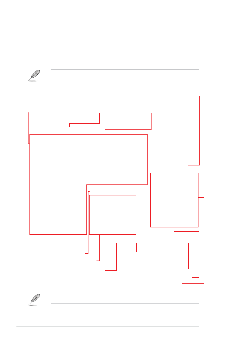
1.2.1 EZ Mode
By default, the EZ Mode screen appears when you enter the BIOS setup program. The EZ
Mode provides you an overview of the basic system information, and allows you to select
the display language, system performance, mode and boot device priority. To access the
Advanced Mode, select Advanced Mode or press the <F7> hotkey for the advanced BIOS
settings.
The default screen for entering the BIOS setup program can be changed. Refer to the
Setup Mode item in section Boot menu for details.
Displays the system properties of the selected mode.
Displays the CPU/motherboard temperature,
CPU voltage output, CPU/chassis/power fan
speed, and SATA information
Selects the display language
of the BIOS setup program
Click < or > to switch EZ System Tuning modes
Creates storage RAID and
configures system overclocking
Enables or disables the SATA RAID mode
for Intel Rapid Storage Technology
Displays the CPU Fan’s speed. Click
the button to manually tune the fans
The boot device options vary depending on the devices you installed to the system.
6
Loads optimized
default settings
Saves the changes
and resets the system
Click to go to Advanced mode
Click to display boot devices
Selects the boot device priority
ASUS X99-E Series BIOS Manual
Search on the FAQ
Page 7
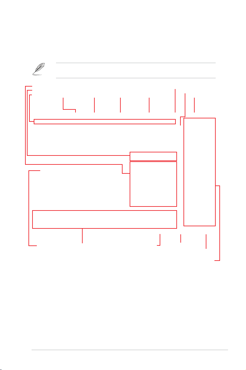
1.2.2 Advanced Mode
The Advanced Mode provides advanced options for experienced end-users to congure
the BIOS settings. The gure below shows an example of the Advanced Mode. Refer to the
following sections for the detailed congurations.
To switch from EZ Mode to Advanced Mode, click Advanced Mode(F7) or press the <F7>
hotkey.
Configuration fields
Pop-up Menu
Menu bar
Language
Menu items
MyFavorite(F3)
General help
Qfan Control(F6)
Last modified settings
Quick Note (F9)
EZ Tuning Wizard(F11)
Go back to EZ Mode
Displays the CPU temperature,
CPU, and memory voltage output
Scroll bar
Hot Keys
Search on the FAQ
ASUS X99-E Series BIOS Manual
7
Page 8

Menu bar
The menu bar on top of the screen has the following main items:
My Favorites
Main
Ai Tweaker
Advanced
Monitor
Boot
Tool
Exit
For saving the frequently-used system settings and conguration.
For changing the basic system conguration
For changing the overclocking settings
For changing the advanced system settings
For displaying the system temperature, power status, and changing the
fan settings.
For changing the system boot conguration
For conguring options for special functions
For selecting the exit options and loading default settings
Menu items
The highlighted item on the menu bar displays the specic items for that menu. For example,
selecting Main shows the Main menu items.
The other items (My Favorites, Ai Tweaker, Advanced, Monitor, Boot, Tool, and Exit) on the
menu bar have their respective menu items.
Submenu items
A greater than sign (>) before each item on any menu screen means that the item has a
submenu. To display the submenu, select the item and press <Enter>.
Language
This button above the menu bar contains the languages that you can select for your BIOS.
Click this button to select the language that you want to display in your BIOS screen.
My Favorites (F3)
This button above the menu bar shows all BIOS items in a Tree Map setup. Select frequentlyused BIOS settings and save it to MyFavorites menu.
Refer to section 1.3 My Favorites for more information.
Q-Fan Control (F6)
This button above the menu bar displays the current settings of your fans. Use this button to
manually tweak the fans to your desired settings.
Refer to section 1.2.3 QFan Control for more information.
EZ Tuning Wizard (F11)
This button above the menu bar allows you to view and tweak the overclocking settings of
your system. It also allows you to change the motherboard’s SATA mode from AHCI to RAID
mode.
Refer to section 1.2.4 EZ Tuning Wizard for more information.
8
ASUS X99-E Series BIOS Manual
Page 9

Search on FAQ
Move your mouse over this button to show a QR code, scan this QR code on your mobile
device to connect to the BIOS FAQ web page of the ASUS support website. You can also
scan the following QR code:
Quick Note (F9)
This button above the menu bar allows you to key in notes of the activities that you have
done in BIOS.
• The Quick Note function does not support the following keyboard functions: delete,
cut, copy, and paste.
• You can only use the alphanumeric characters to enter your notes.
Hot keys
This button above the menu bar contains the navigation keys for the BIOS setup program.
Use the navigation keys to select items in the menu and change the settings.
Scroll bar
A scroll bar appears on the right side of a menu screen when there are items that do not t
on the screen. Press the Up/Down arrow keys or <Page Up> / <Page Down> keys to display
the other items on the screen.
General help
At the bottom of the menu screen is a brief description of the selected item. Use <F12> key
to capture the BIOS screen and save it to the removable storage device.
Configuration fields
These elds show the values for the menu items. If an item is user-congurable, you can
change the value of the eld opposite the item. You cannot select an item that is not
user-congurable.
A congurable eld is highlighted when selected. To change the value of a eld, select it and
press <Enter> to display a list of options.
Last Modified button
This button shows the items that you last modied and saved in BIOS Setup.
ASUS X99-E Series BIOS Manual
9
Page 10

1.2.3 QFan Control
The QFan Control allows you to set a fan prole or manually congure the operating speed of
your CPU and chassis fans.
Click to select a fan to be
configured
Select a profile to apply to
your fans
Click to activate
Click to apply the fan setting
Click to undo the
changes
PWM Mode
Click to go back to main menu
Click to activate DC Mode
Select to manually configure
your fans
10
ASUS X99-E Series BIOS Manual
Page 11

Configuring fans manually
Select Manual from the list of proles to manually congure your fans’ operating speed.
Speed points
Select to manually
configure your fans
To congure your fans:
1. Select the fan that you want to congure and to view its current status.
2. Click and drag the speed points to adjust the fans’ operating speed.
3. Click Apply to save the changes then click Exit (ESC).
ASUS X99-E Series BIOS Manual
11
Page 12

1.2.4 EZ Tuning Wizard
EZ Tuning Wizard allows you to easily overclock your CPU and DRAM, computer usage, and
CPU fan to their best settings. You can also set RAID in your system using this feature.
OC setup
RAID setup
OC Tuning
To start OC Tuning:
1. Press <F11> on your keyboard or click
EZ Tuning Wizard screen.
2. Click OC
then click Next.
3. Select a PC scenario Daily Computing or Gaming/Media Editing, then click Next.
from the BIOS screen to open
12
ASUS X99-E Series BIOS Manual
Page 13

4. Select a Main Cooling System BOX cooler, Tower cooler, Water cooler, or I’m not
sure, then click Next.
5. After selecting the Main Cooling System, click Next then click Yes to start the OC
Tuning.
Creating RAID
To create RAID:
1. Press <F11> on your keyboard or click
EZ Tuning Wizard screen.
2. Click RAID
then click Yes.
• Ensure that your HDDs have no existing RAID volumes.
• Ensure to connect your HDDs to Intel
®
SATA connectors.
3. Check the available storage disk drives, then click Next.
from the BIOS screen to open
ASUS X99-E Series BIOS Manual
13
Page 14

4. Select the type of storage for your RAID, Easy Backup or Super Speed, then click
Next.
a. For Easy Backup, click Next then select from Easy Backup (RAID 1) or Easy
Backup (RAID 10).
You can only select Easy Backup (RAID 10) if you connect four (4) HDDs.
b. For Super Speed, click Next then select from Super Speed (RAID 0) or Super
Speed (RAID 5).
5. After selecting the type of RAID, click Next then click Yes to continue the RAID setup.
6. After the RAID setup is done, click Yes to exit the setup then click OK to reset your
system.
14
ASUS X99-E Series BIOS Manual
Page 15

1.3 My Favorites
My Favorites is your personal space where you can easily save and access your favorite
BIOS items.
My Favorites comes with several performance, power saving, and fast boot related items by
default. You can personalize this screen by adding or removing items.
ASUS X99-E Series BIOS Manual
15
Page 16
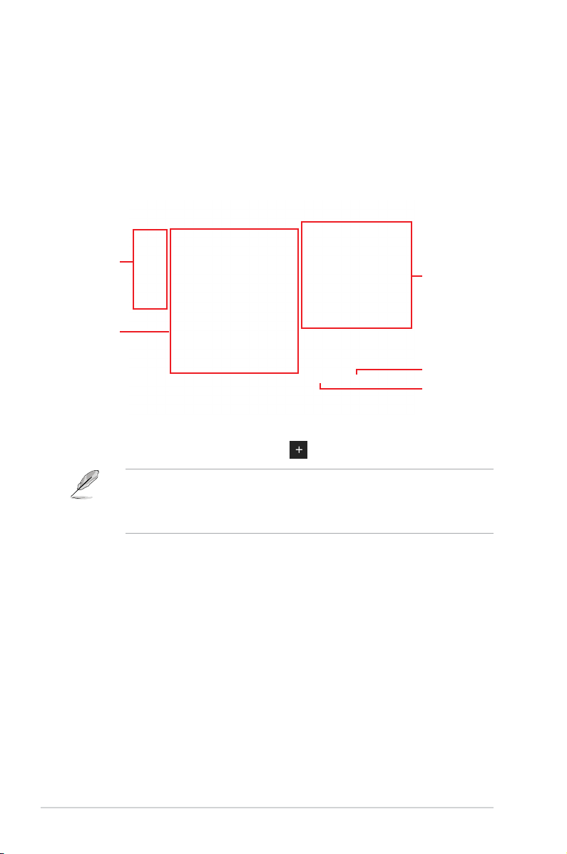
Adding items to My Favorites
To add BIOS items:
1. Press <F3> on your keyboard or click
from the BIOS screen to open
Setup Tree Map screen.
2. On the Setup Tree Map screen, select the BIOS items that you want to save in My
Favorites screen.
Main menu panel
Selected shortcut
items
Submenu panel
Delete all favorite
items
Recover to default
favorite items
3. Select an item from main menu panel, then click the submenu that you want to save as
favorite from the submenu panel and click
You cannot add the following items to My Favorite items:
• Items with submenu options
• User-managed items such as language and boot order
or press <Enter> on your keyboard.
4. Click Exit (ESC) or press <Esc> key to close Setup Tree Map screen.
5. Go to My Favorites menu to view the saved BIOS items.
16
ASUS X99-E Series BIOS Manual
Page 17

1.4 Main menu
The Main menu screen appears when you enter the Advanced Mode of the BIOS Setup
program. The Main menu provides you an overview of the basic system information, and
allows you to set the system date, time, language, and security settings.
Security
The Security menu items allow you to change the system security settings.
• If you have forgotten your BIOS password, erase the CMOS Real Time Clock (RTC)
RAM to clear the BIOS password. See section 1.1.6 Onboard buttons and switches
in your user manual for information on how to erase the RTC RAM via the Clear
CMOS button.
• The Administrator or User Password items on top of the screen show the default [Not
Installed]. After you set a password, these items show [Installed].
ASUS X99-E Series BIOS Manual
17
Page 18

Administrator Password
If you have set an administrator password, we recommend that you enter the administrator
password for accessing the system. Otherwise, you might be able to see or change only
selected elds in the BIOS setup program.
To set an administrator password:
1. Select the Administrator Password item and press <Enter>.
2. From the Create New Password box, key in a password, then press <Enter>.
3. Conrm the password when prompted.
To change an administrator password:
1. Select the Administrator Password item and press <Enter>.
2. From the Enter Current Password box, key in the current password, then press
<Enter>.
3. From the Create New Password box, key in a new password, then press <Enter>.
4. Conrm the password when prompted.
To clear the administrator password, follow the same steps as in changing an administrator
password, but press <Enter> when prompted to create/conrm the password. After you clear
the password, the Administrator Password item on top of the screen shows [Not Installed].
User Password
If you have set a user password, you must enter the user password for accessing the system.
The User Password item on top of the screen shows the default [Not Installed]. After you set
a password, this item shows [Installed.]
To set a user password:
1. Select the User Password item and press <Enter>.
2. From the Create New Password box, key in a password, then press <Enter>.
3. Conrm the password when prompted.
To change a user password:
1. Select the User Password item and press <Enter>.
2. From the Enter Current Password box, key in the current password, then press
<Enter>.
3. From the Create New Password box, key in a new password, then press <Enter>.
4. Conrm the password when prompted.
To clear the user password, follow the same steps as in changing a user password, but press
<Enter> when prompted to create/conrm the password. After you clear the password, the
User Password item on top of the screen shows [Not Installed].
18
ASUS X99-E Series BIOS Manual
Page 19

1.5 Ai Tweaker menu
The Ai Tweaker menu items allow you to congure overclocking-related items.
Be cautious when changing the settings of the Ai Tweaker menu items. Incorrect eld
values can cause the system to malfunction.
The conguration options for this section vary depending on the CPU and DIMM model you
installed on the motherboard.
Scroll down to display other BIOS items.
Ai Overclock Tuner
This item allows you to select the CPU overclocking options to achieve the desired CPU
internal frequency. Select any of these preset overclocking conguration options:
[Auto] Loads the optimal settings for the system.
[Manual] Automatically optimizes the CPU ratio and BCLK frequency.
[XMP] If you install memory modules supporting the eXtreme Memory Prole
(XMP) Technology, choose this item to set the proles supported by your
memory modules for optimizing the system performance.
The [X.M.P.] conguration option appears only when you install memory modules
supporting the eXtreme Memory Prole(X.M.P.) Technology.
ASUS X99-E Series BIOS Manual
19
Page 20

When the Ai Overclock Tuner is set to [Manual], the following items appear.
CPU Strap
This item allows you to select a strap close to your target BCLK (base clock) for an
extreme overclocking, or leave it at [Auto] for the BIOS to upgrade.
Conguration options: [Auto] [100MHz] [125MHz] [167MHz] [250MHz]
The following item appears only when you set the CPU Strap to [100MHz], [125MHz],
[167MHz], or [250MHz].
Source Clock Tuner
This item allows you to select the source clock based on the assigned CPU
strap for a better overclocking capability.
Conguration options: [8Ohm dbl] [7Ohm dbl] [6Ohm dbl] [5Ohm dbl]
[4Ohm dbl] [3Ohm dbl] [2Ohm dbl]
PLL Selection
This item is set to LC PLL by default for better stability. Select SB PLL when the BCLK
(base clock) frequency is far away from 100 MHz. This may affect the function of other
devices that need precise clock jitters.
Conguration options: [Auto] [LC PLL] [SB PLL]
Filter PLL
Set this item to high BCLK (base clock) mode when using a very high BCLK to improve
overclocking capability.
Conguration options: [Auto] [Low BCLK Mode] [High BCLK Mode]
BCLK Frequency
This item allows you to set the BCLK (base clock) frequency to enhance the system
performance. Use the <+> or <-> to adjust the value. The values range from 80.0 MHz
to 300.0 MHz.
We recommend you to set the value based on the CPU specication, as high BCLK
frequencies may damage the CPU permanently.
Initial BCLK Frequency
This item allows you to set the initial BCLK (base clock) frequency to start overclocking
to the assigned BCLK frequency. Use the <+> or <-> to adjust the value. The initial
BCLK frequency cannot be less than 80.0 MHz.
ASUS MultiCore Enhancement
[Auto] This item allows you to maximize the oveclocking performance optimized
[Disabled] This item allows you to set to default core ratio settings.
20
by ASUS core ratio settings.
ASUS X99-E Series BIOS Manual
Page 21

CPU Core Ratio
This item allows you to set the CPU core ratio limit per core or synchronize automatically to
all cores.
Conguration options: [Auto] [Sync All Cores] [By Core Usage] [By Specic Core]
When the CPU Core Ratio is set to [Sync All Cores], the following item appears.
1-Core Ratio Limit
Enter [Auto] to apply the CPU default Turbo Ratio setting or manually
assign a 1-Core Limit value that must be higher than or equal to the 2-Core
Ratio Limit.
When the CPU Core Ratio is set to [By Core Usage], the following item appears.
1-Core Ratio Limit
Enter [Auto] to apply the CPU default Turbo Ratio setting or manually
assign a 1-core ratio limit that must be higher than or equal to the 2-core
ratio limit.
2-Core Ratio Limit
Enter [Auto] to apply the CPU default Turbo Ratio setting or manually
assign a 2-core ratio limit that must be higher than or equal to the 3-core
ratio limit.
If you assign a value for 2-Core Ratio Limit, do not set the 1-Core Ratio Limit to [Auto].
3-Core Ratio Limit
Enter [Auto] to apply the CPU default Turbo Ratio setting or manually
assign a 3-core ratio limit that must be higher than or equal to the 4-core
ratio limit.
If you assign a value for 3-Core Ratio Limit, do not set the 1-Core Ratio Limit and 2-Core
Ratio Limit to [Auto].
4-Core Ratio Limit
Enter [Auto] to apply the CPU default Turbo Ratio setting or manually
assign a 4-core ratio limit that must be higher than or equal to the 5-core
ratio limit.
If you assign a value for 4-Core Ratio Limit, do not set the 1-Core Ratio Limit, 2-Core Ratio
Limit, and 3-Core Ratio Limit to [Auto].
ASUS X99-E Series BIOS Manual
21
Page 22

5-Core Ratio Limit
Enter [Auto] to apply the CPU default Turbo Ratio setting or manually
assign a 5-core ratio limit that must be higher than or equal to the 6-core
ratio limit.
If you assign a value for 5-Core Ratio Limit, do not set the 1-Core Ratio Limit, 2-Core Ratio
Limit, 3-Core Ratio Limit, and 4-Core Ratio Limit to [Auto].
6-Core Ratio Limit
Enter [Auto] to apply the CPU default Turbo Ratio setting or manually
assign a 6-core ratio limit that must be higher than or equal to the 7-core
ratio limit.
If you assign a value for 6-Core Ratio Limit, do not set the 1-Core Ratio Limit, 2-Core Ratio
Limit, 3-Core Ratio Limit, 4-Core Ratio Limit, and 5-Core Ratio Limit to [Auto].
7-Core Ratio Limit
Enter [Auto] to apply the CPU default Turbo Ratio setting or manually
assign a 7-core ratio limit that must be higher than or equal to the 8-core
ratio limit.
If you assign a value for 7-Core Ratio Limit, do not set the 1-Core Ratio Limit, 2-Core Ratio
Limit, 3-Core Ratio Limit, 4-Core Ratio Limit, 5-Core Ratio Limit, and 6-Core Ratio Limit to
[Auto].
8-Core Ratio Limit
Enter [Auto] to apply the CPU default Turbo Ratio setting or manually
assign a 8-core ratio limit that must be higher than or equal to the 9-core
ratio limit.
If you assign a value for 8-Core Ratio Limit, do not set the 1-Core Ratio Limit, 2-Core Ratio
Limit, 3-Core Ratio Limit, 4-Core Ratio Limit, 5-Core Ratio Limit, 6-Core Ratio Limit, and
7-Core Ratio Limit to [Auto].
9-Core Ratio Limit
Enter [Auto] to apply the CPU default Turbo Ratio setting or manually
assign a 9-core ratio limit that must be higher than or equal to the 10-core
ratio limit.
If you assign a value for 9-Core Ratio Limit, do not set the 1-Core Ratio Limit, 2-Core Ratio
Limit, 3-Core Ratio Limit, 4-Core Ratio Limit, 5-Core Ratio Limit, 6-Core Ratio Limit, 7-Core
Ratio Limit, and 8-Core Ratio Limit to [Auto].
10-Core Ratio Limit
Enter [Auto] to apply the CPU default Turbo Ratio setting or manually
assign a 10-core ratio limit that must be lower than or equal to the 9-core
ratio limit.
If you assign a value for 10-Core Ratio Limit, do not set the 1-Core Ratio Limit, 2-Core
Ratio Limit, 3-Core Ratio Limit, 4-Core Ratio Limit, 5-Core Ratio Limit, 6-Core Ratio Limit,
7-Core Ratio Limit, 8-Core Ratio Limit, and 9-Core Ratio Limit to [Auto].
22
ASUS X99-E Series BIOS Manual
Page 23

AVX Instruction Core Ratio Negative Offset
This item allows you to subtract a value from your core ratio at which AVX applications run.
Conguration options: [Auto] [1] – [31]
Min. CPU Cache Ratio
This item allows you to set the minimum possible ratio on the Uncore part of the processor.
Use the <+> or <-> keys to adjust the value. The values depend on the CPU installed.
Max. CPU Cache Ratio
This item allows you to set the maximum possible ratio on the Uncore part of the processor.
Use the <+> or <-> keys to adjust the value. The values depend on the CPU installed.
Internal PLL Overvoltage
This item allows you to enable the internal PLL Overvoltage for K-SKU and X-SKU CPUs to
get the extreme overclocking capability.
Conguration options: [Auto] [Disabled] [Enabled]
BCLK Frequency : DRAM Frequency Ratio
[Auto] The BCLK frequency to DRAM frequency ratio will be set to the optimized
[100:133] The BCLK frequency to DRAM frequency ratio will be set to 100:133.
[100:100] The BCLK frequency to DRAM frequency ratio will be set to 100:100.
setting.
DRAM Frequency
This item allows you to set the memory operating frequency. The congurable options vary
with the BCLK (base clock) frequency setting. Select the auto mode to apply the optimized
setting.
Conguration options: [Auto] [DDR4-800MHz] - [DDR4-4000MHz]
TPU
This item allows you to automatically overclock the CPU and DRAM frequencies and voltage
for an enhanced system performance.
[Keep Current Settings] Keep the current settings without changing anything.
[TPU I] Applies air cooling overclocking conditions.
[TPU II] Applies water cooling overclocking conditions.
Ensure to use water cooling device before selecting [TPU II].
EPU Power Saving Mode
The ASUS EPU (Energy Processing Unit) sets the CPU in its minimum power consumption
settings. Enable this item to set lower CPU VCCIN and Vcore voltages and achieve the best
energy saving condition.
Conguration options: [Disabled] [Enabled]
ASUS X99-E Series BIOS Manual
23
Page 24

DRAM Timing Control
The subitems in this menu allow you to set the DRAM timing control features. Use the <+>
or <-> keys to adjust the value. To restore the default setting, type [auto] using the keyboard
and press the <Enter> key.
Changing the values in this menu may cause the system to become unstable! If this
happens, revert to the default settings.
Primary Timings
DRAM CAS# Latency
Conguration options: [Auto] [1] – [31]
DRAM RAS# to CAS# Delay
Conguration options: [Auto] [1] – [31]
DRAM RAS# PRE Time
Conguration options: [Auto] [1] – [31]
DRAM RAS# ACT Time
Conguration options: [Auto] [1] – [63]
DRAM COMMAND Rate
Conguration options: [Auto] [Timing 1T] – [Timing 3T]
Secondary Timings
DRAM RAS# to RAS# Delay
Conguration options: [Auto] [1] – [7]
DRAM RAS# to RAS# Delay L
Conguration options: [Auto] [1] – [7]
DRAM REF Cycle Time
Conguration options: [Auto] [1] – [1023]
DRAM Refresh Interval
Conguration options: [Auto] [1] – [32767]
DRAM WRITE Recovery Time
Conguration options: [Auto] [1] – [31]
DRAM READ to PRE Time
Conguration options: [Auto] [1] – [15]
DRAM FOUR ACT WIN Time
Conguration options: [Auto] [1] – [63]
DRAM WRITE to READ Delay
Conguration options: [Auto] [1] – [15]
DRAM WRITE to READ Delay L
Conguration options: [Auto] [1] – [15]
24
ASUS X99-E Series BIOS Manual
Page 25

DRAM CKE Minimum Pulse Width
Conguration options: [Auto] [4] – [8]
DRAM Write Latency
Conguration options: [Auto] [1] – [31]
Third Timings
tRRDR
Conguration options: [Auto] [0] - [7]
tRRDD
Conguration options: [Auto] [0] - [7]
tWWDR
Conguration options: [Auto] [0] - [7]
tWWDD
Conguration options: [Auto] [0] - [7]
tRWDR
Conguration options: [Auto] [0] - [7]
tWRDR
Conguration options: [Auto] [0] - [7]
tWRDD
Conguration options: [Auto] [0] - [7]
tRWSR
Conguration options: [Auto] [0] - [7]
tCCD
Conguration options: [Auto] [0] - [7]
tUWRDR
Conguration options: [Auto] [0] - [3]
tRWDR2
Conguration options: [Auto] [0] - [31]
tRWDD
Conguration options: [Auto] [0] - [31]
tRWSR2
Conguration options: [Auto] [0] - [31]
tWRDD2
Conguration options: [Auto] [0] - [31]
tCCDWR
Conguration options: [Auto] [0] - [7]
tCCD_L
Conguration options: [Auto] [1] - [3]
ASUS X99-E Series BIOS Manual
25
Page 26

RTL IOL control
DRAM RTL INIT Value
Conguration options: [Auto] [0] - [127]
DRAM RTL (CHA D0 R0)
Conguration options: [Auto] [0] - [127]
DRAM RTL (CHA D0 R1)
Conguration options: [Auto] [0] - [127]
DRAM RTL (CHA D1 R0)
Conguration options: [Auto] [0] - [127]
DRAM RTL (CHA D1 R1)
Conguration options: [Auto] [0] - [127]
DRAM RTL (CHB D0 R0)
Conguration options: [Auto] [0] - [127]
DRAM RTL (CHB D0 R1)
Conguration options: [Auto] [0] - [127]
DRAM RTL (CHB D1 R0)
Conguration options: [Auto] [0] - [127]
DRAM RTL (CHB D1 R1)
Conguration options: [Auto] [0] - [127]
DRAM RTL (CHC D0 R0)
Conguration options: [Auto] [0] - [127]
DRAM RTL (CHC D0 R1)
Conguration options: [Auto] [0] - [127]
DRAM RTL (CHC D1 R0)
Conguration options: [Auto] [0] - [127]
DRAM RTL (CHC D1 R1)
Conguration options: [Auto] [0] - [127]
DRAM RTL (CHD D0 R0)
Conguration options: [Auto] [0] - [127]
DRAM RTL (CHD D0 R1)
Conguration options: [Auto] [0] - [127]
DRAM RTL (CHD D1 R0)
Conguration options: [Auto] [0] - [127]
DRAM RTL (CHD D1 R1)
Conguration options: [Auto] [0] - [127]
DRAM IOL (CHA D0 R0)
Conguration options: [Auto] [0] - [255]
DRAM IOL (CHA D0 R1)
Conguration options: [Auto] [0] - [255]
DRAM IOL (CHA D1 R0)
Conguration options: [Auto] [0] - [255]
DRAM IOL (CHA D1 R1)
Conguration options: [Auto] [0] - [255]
26
ASUS X99-E Series BIOS Manual
Page 27

IO control
DRAM IOL (CHB D0 R0)
Conguration options: [Auto] [0] - [255]
DRAM IOL (CHB D0 R1)
Conguration options: [Auto] [0] - [255]
DRAM IOL (CHB D1 R0)
Conguration options: [Auto] [0] - [255]
DRAM IOL (CHB D1 R1)
Conguration options: [Auto] [0] - [255]
DRAM IOL (CHC D0 R0)
Conguration options: [Auto] [0] - [255]
DRAM IOL (CHC D0 R1)
Conguration options: [Auto] [0] - [255]
DRAM IOL (CHC D1 R0)
Conguration options: [Auto] [0] - [255]
DRAM IOL (CHC D1 R1)
Conguration options: [Auto] [0] - [255]
DRAM IOL (CHD D0 R0)
Conguration options: [Auto] [0] - [255]
DRAM IOL (CHD D0 R1)
Conguration options: [Auto] [0] - [255]
DRAM IOL (CHD D1 R0)
Conguration options: [Auto] [0] - [255]
DRAM IOL (CHD D1 R1)
Conguration options: [Auto] [0] - [255]
MC Data VREF
MC Vref(CHA)
Conguration options: [Auto] [50.000] - [99.911]
MC Vref(CHB)
Conguration options: [Auto] [50.000] - [99.911]
MC Vref(CHC)
Conguration options: [Auto] [50.000] - [99.911]
MC Vref(CHD)
Conguration options: [Auto] [50.000] - [99.911]
RAM Data VREF
DRAM Vref(CHA)
Conguration options: [Auto] [60.000] - [99.000]
DRAM Vref(CHB)
Conguration options: [Auto] [60.000] - [99.000]
DRAM Vref(CHC)
Conguration options: [Auto] [60.000] - [99.000]
DRAM Vref(CHD)
Conguration options: [Auto] [60.000] - [99.000]
ASUS X99-E Series BIOS Manual
27
Page 28

CTL Data VREF
DRAM Vref(CHAB) Sign
[+] To offset the voltage by a positive value.
[–] To offset the voltage by a negative value.
DRAM Vref(CHAB)
Conguration options: [Auto] [0.00000] - [2.0000]
DRAM Vref(CHCD) Sign
[+] To offset the voltage by a positive value.
[–] To offset the voltage by a negative value.
DRAM Vref(CHCD)
Conguration options: [Auto] [0.00000] - [2.0000]
Misc.
DRAM Eventual Voltage(CHA, CHB)
Allows you to set the voltage for the DRAM on the left.
Conguration options: [Auto] [0.800] - [1.900]
DRAM Eventual Voltage(CHC, CHD)
Allows you to set the voltage for the DRAM on the right.
Conguration options: [Auto] [0.800] - [1.900]
DRAM CLK Period
This item allows you to set a DRAM clock period.
Conguration options: [Auto] [1] – [19]
Memory Optimize Control
This item allows you to optimize the memory control.
Conguration options: [Auto] [Disabled] [Enabled]
Enhanced Training(CHA)
Conguration options: [Auto] [Disabled] [Enabled]
Enhanced Training(CHB)
Conguration options: [Auto] [Disabled] [Enabled]
Enhanced Training(CHC)
Conguration options: [Auto] [Disabled] [Enabled]
Enhanced Training(CHD)
Conguration options: [Auto] [Disabled] [Enabled]
28
ASUS X99-E Series BIOS Manual
Page 29

DRAM Training
MemTest
This item allows you to enable or disable the memory testing.
Conguration options: [Auto] [Disabled] [Enabled]
Attempt Fast Boot
This item allows the portion of the memory reference code to be skipped when possible
to increase boot speed.
Conguration options: [Auto] [Disabled] [Enabled]
Attempt Fast Cold Boot
This item allows the portion of the memory reference code to be skipped when possible
to increase boot speed.
Conguration options: [Auto] [Disabled] [Enabled]
DRAM Training
[Auto] System automatically sets the status according to the installed
DRAM.
[Ignore] System ignores the DRAM training test function.
[Enabled] System closes the DRAM channel when it has some issues.
[Smart] System automatically trains the DRAM for better stability.
DRAM SPD Write
For advanced programming only. Enable DRAM SPD write to enable memory SMBus
programming
Conguration options: [Disabled] [Enabled]
ASUS X99-E Series BIOS Manual
29
Page 30

External DIGI+ Power Control
CPU Load-line Calibration
Load-line is dened by Intel
working voltage decreases proportionally to CPU loading. Higher load-line calibration
could get higher voltage and good overclocking performance, but increases the CPU
and VRM thermal conditions. Select from levels 1 to 9 to adjust the CPU power voltage
from 0% to 125%.
Conguration options [Auto] [Level 1] - [Level 9]
The actual performance boost may vary depending on your CPU specication.
DO NOT remove the thermal module. The thermal conditions should be monitored.
CPU VRM Switching Frequency
This item affects the VRM transient response speed and the component thermal
production. Select [Manual] to congure a higher frequency for a quicker transient
response speed.
Conguration options: [Auto] [Manual]
DO NOT remove the thermal module. The thermal conditions should be monitored.
The following item appears only when you set the CPU VRM Switching Frequency to
[Manual].
Fixed CPU VRM Switching Frequency (KHz)
This item allows you to set a higher frequency for a quicker transient
response speed. Use the <+> or <-> to adjust the value. The values range
from 300 KHz to 600 KHz with an interval of 50 KHz.
®
specication and affects CPU power voltage. The CPU
Do not remove the thermal module when the manual mode is selected. The thermal
conditions should be monitored.
30
ASUS X99-E Series BIOS Manual
Page 31

The following item appears only when the CPU VRM Switching Frequency is set to [Auto].
VRM Spread Spectrum
This item allows to enhance the system stability.
Conguration options: [Auto] [Disabled] [Enabled]
CPU Power Phase Control
This item allows you to set the power phase control of the CPU.
[Auto] Automatically set the phase control mode.
[Standard] The phase control will be based on the CPU command.
[Optimized] Set to the ASUS optimized phase tuning prole.
[Extreme] Set to the full phase mode.
[Power Phase Response] The phase number will be adjusted by the current(A) step.
DO NOT remove the thermal module when setting this item to [Power Phase Response]
or [Extreme]. The thermal conditions should be monitored.
CPU Power Duty Control
DIGI + VRM Duty Control adjusts the current of every VRM phase and the thermal
conditions of every phase component.
[T. Probe] Select to set the VRM thermal balance mode.
[Extreme] Select to set the VRM current balance mode.
DO NOT remove the thermal module. The thermal conditions should be monitored.
CPU Current Capability
This item provides a total power range for CPU overclocking. A higher value setting
provides higher power consumption delivery and extends the overclocking frequency
range simultaneously.
Conguration options: [Auto] [100%] [110%] [120%] [130%] [140%]
Congure higher values when overclocking or under a high CPU loading for extra power
support.
CPU Power Thermal Control
Higher temperature provides a wider CPU power thermal range and extends the
overclocking tolerance to enlarge the overclocking potential.
Conguration options: [120] - [141]
DO NOT remove the thermal module. The thermal conditions should be monitored
ASUS X99-E Series BIOS Manual
31
Page 32

DRAM Current Capability(CHA, CHB)
This item provides a total power range for DRAM overclocking. A higher value setting
provides higher power consumption delivery and extends the overclocking frequency
range simultaneously.
Conguration options: [100%] [110%] [120%] [130%]
Congure higher values when overclocking or under a high CPU loading for extra power
support.
DRAM Current Capability(CHC, CHD)
This item provides a total power range for DRAM overclocking. A higher value setting
provides higher power consumption delivery and extends the overclocking frequency
range simultaneously.
Conguration options: [100%] [110%] [120%] [130%]
Congure higher values when overclocking or under a high CPU loading for extra power
support.
DRAM Switching Frequency(CHA, CHB)
This item affects the VRM transient response speed and the component thermal
production. Select [Manual] to congure a higher frequency for a quicker transient
response speed.
Conguration options: [Auto] [Manual]
DO NOT remove the thermal module. The thermal conditions should be monitored.
The following item appears only when you set the CPU VRM Switching Frequency to
[Manual].
Fixed DRAM-AB Switching Frequency (KHz)
This item allows you to set a higher frequency for a quicker transient
response speed. Use the <+> or <-> to adjust the value. The values range
from 300 KHz to 500 KHz with an interval of 50 KHz.
Do not remove the thermal module when the manual mode is selected. The thermal
conditions should be monitored.
DRAM Switching Frequency(CHC, CHD)
This item affects the VRM transient response speed and the component thermal
production. Select [Manual] to congure a higher frequency for a quicker transient
response speed.
Conguration options: [Auto] [Manual]
DO NOT remove the thermal module. The thermal conditions should be monitored.
32
ASUS X99-E Series BIOS Manual
Page 33

The following item appears only when you set the CPU VRM Switching Frequency to
[Manual].
Fixed DRAM-CD Switching Frequency (KHz)
This item allows you to set a higher frequency for a quicker transient
response speed. Use the <+> or <-> to adjust the value. The values range
from 300 KHz to 500 KHz with an interval of 50 KHz.
Do not remove the thermal module when the manual mode is selected. The thermal
conditions should be monitored.
DRAM Power Phase Control (CHA, CHB)
[Standard] The phase control will be based on the CPU command.
[Optimized] Set to the ASUS optimized phase tuning prole.
DRAM Power Phase Control (CHC, CHD)
[Standard] The phase control will be based on the CPU command.
[Optimized] Set to the ASUS optimized phase tuning prole.
Internal CPU Power Management
The subitems in this menu allow you to set the CPU ratio and features.
Enhanced Intel SpeedStep Technology
Allows the operating system to dynamically adjust the processor voltage and cores
frequency to decrease the average power consumption and decrease average heat
production.
Conguration options: [Enabled] [Disabled]
Turbo Mode
Allows you to enable your processor cores to run faster than the base operating
frequency when it is below power, current and specication limit.
Conguration options: [Disabled] [Enabled]
Turbo Mode Parameters
The following items appear only when you set the Turbo Mode to [Enabled].
Long Duration Package Power Limit
As know as the power limit 1 in Watts. The default value will be the
TDP(thermal design power). The turbo ratio can be maintained for a
duration to exceed the TDP for the maximum system performance.
Conguration options: [Auto] [1] - [4095]
Package Power Time Window
As know as the power limit 1 in Watts. The value indicates the maintained
duration for the turbo ratio to exceed TPD(thermal design power).
Conguration options: [Auto] [1] - [127]
ASUS X99-E Series BIOS Manual
33
Page 34

Short Duration Package Power Limit
As know as the power limit 2 in Watts. It is the second power limit to
provide a rapid protection when the package power exceed power limit
1. The default setting is 1.25 times the power limit 1. According to Intel,
the platform must be capable of supporting the duration for up to 10 msec
when the turbo ratio exceeds the power limit 2. The ASUS motherboards
can support the duration for a linger time.
Conguration options: [Auto] [1] - [4095]
CPU Integrated VR current Limit
This item allows you to set a higher current limit to prevent a frequency or power
throttling when overclocking.
Conguration options: [Auto] [0.125] - [1023.875]
CPU Internal Power Fault Control
CPU Integrated VR Fault Management
Disable this item to prevent FIVR(fully integrated voltage regulator) from tripping when
doing over-voltage. It is recommended to disable this item when overcolocking.
Conguration options: [Auto] [Enabled] [Disabled]
CPU Internal Power Configuration
CPU Integrated VR current Limit
Select balanced mode to improve power saving when the CPU is in a low power state.
Select high performance mode to make the FIVR(fully integrated voltage regulator)
work in high performance at all times.
Conguration options: [Auto] [High Performance] [Balanced]
Tweaker’s Paradise
The subitems in this menu allow you to access various tweaking options.
The subitems in this menu will vary per CPU model.
Extreme Over-voltage
Enable this item to allow higher voltages for overclocking, but the CPU lifetime will not be
guaranteed.
Conguration options: [Disabled] [Enabled]
This item can only be enabled when the onboard CPU_OV jumper is switched on.
34
ASUS X99-E Series BIOS Manual
Page 35

CPU Core Voltage
Congures the mode of voltage fed to the cores of the processor.
Conguration options: [Auto] [Manual Mode] [Offset Mode] [Adaptive Mode]
The following items appear only when you set the CPU Core Voltage to [Manual Mode].
CPU Core Voltage Override
Allows you to congure the CPU Core voltage.
Conguration options: [Auto] [0.001] - [1.920]
The following items appear only when you set the CPU Core Voltage to [Offset Mode].
Offset Mode Sign
[+] To offset the voltage by a positive value.
[–] To offset the voltage by a negative value.
CPU Core Voltage Offset
This item allows you to congure the CPU core voltage offset value.
Conguration options: [Auto] [0.001] - [0.999]
The following items appear only when you set the CPU Core Voltage to [Adaptive Mode].
Offset Mode Sign
[+] To offset the voltage by a positive value.
[–] To offset the voltage by a negative value.
CPU Core Voltage Offset
This item allows you to congure the CPU core voltage offset value.
Conguration options: [Auto] [0.001] - [0.999]
Additional Turbo Mode CPU Core Voltage
This item allows you to congure the CPU core voltage offset value.
Conguration options: [0.001] - [1.920]
CPU Cache Voltage
Congures the mode of voltage fed to the uncores of the processor.
Conguration options: [Auto] [Manual Mode] [Offset Mode] [Adaptive Mode]
The following items appear only when you set the CPU Cache Voltage to [Manual Mode].
CPU Cache Voltage Override
Allows you to congure the CPU Cache voltage.
Conguration options: [Auto] [0.001] - [1.920]
ASUS X99-E Series BIOS Manual
35
Page 36

The following items appear only when you set the CPU Cache Voltage to [Offset Mode].
Offset Mode Sign
[+] To offset the voltage by a positive value.
[–] To offset the voltage by a negative value.
CPU Cache Voltage Offset
This item allows you to congure the CPU core voltage offset value.
Conguration options: [Auto] [0.001] - [0.999]
The following items appear only when you set the CPU Cache Voltage to [Adaptive
Mode].
Offset Mode Sign
[+] To offset the voltage by a positive value.
[–] To offset the voltage by a negative value.
CPU Cache Voltage Offset
This item allows you to congure the CPU core voltage offset value.
Conguration options: [Auto] [0.001] - [0.999]
Additional Turbo Mode CPU Cache Voltage
This item allows you to congure the CPU core voltage offset value.
Conguration options: [0.001] - [1.920]
CPU System Agent Voltage Offset Mode Sign
[+] To offset the voltage by a positive value.
[–] To offset the voltage by a negative value.
CPU System Agent Voltage Offset
This item allows you to congure the amount of voltage fed to the system agent of the CPU
including the PCI-E controller and the PCU(power control unit). Congure a high system
agent voltage may enhance the overclocking capability.
Conguration options: [Auto] [0.001] - [0.999]
36
ASUS X99-E Series BIOS Manual
Page 37

CPU SVID Support
Disable this item to stop the CPU from communicating with the external voltage regulator.
Conguration options: [Auto] [Disabled] [Enabled]
CPU Input Voltage
This item allows you to congure the input voltage for the CPU by the external voltage
regulator.
Conguration options: [Auto] [0.800] - [2.700]
The following items appear only when you set the CPU SVID Support to [Enabled].
SVID Voltage Override
This item allows you to set a VCCIN for the CPU during initial part of POST. Use the
<+> or <-> key to adjust the value. The values range from 0.001 V to 2.440V at 0.001V
increment.
Conguration options: [Auto] [0.001] - [2.440]
DRAM SVID Support
Disable this item to stop the DRAM from communicating with the external voltage regulator.
Conguration options: [Auto] [Disabled] [Enabled]
DRAM Voltage(CHA, CHB)
This item allows you to congure the voltage for the DRAM on the left.
Conguration options: [Auto] [0.800] - [1.900]
According to Intel® CPU specications, DIMMs with voltage requirement over 1.65 V may
damage the CPU permanently. We recommend that you install the DIMMs with the voltage
requirement below 1.65 V.
DRAM Voltage(CHC, CHD)
This item allows you to congure the voltage for the DRAM on the right.
Conguration options: [Auto] [0.800] - [1.900]
According to Intel® CPU specications, DIMMs with voltage requirement over 1.65 V may
damage the CPU permanently. We recommend that you install the DIMMs with the voltage
requirement below 1.65 V.
PCH Core Voltage
This item allows you to congure the voltage for PCH(platform controller hub).
Conguration options: [Auto] [0.70000] - [1.80000]
PCH I/O Voltage
This item allows you to congure the I/O voltage for PCH(platform controller hub).
Conguration options: [Auto] [1.20000] - [2.20000]
ASUS X99-E Series BIOS Manual
37
Page 38

VCCIO CPU 1.05V Voltage
This item allows you to congure the main power supply for the CPU REF.
Conguration options: [Auto] [0.70000] - [1.80000]
VCCIO PCH 1.05V Voltage
This item allows you to congure the main power supply for the PCH REF.
Conguration options: [Auto] [0.70000] - [1.80000]
VTTDDR Voltage(CHA, CHB)
This item allows you to congure the main power supply for the PCH REF.
Conguration options: [Auto] [0.20000] - [1.00000]
VTTDDR Voltage(CHC, CHD)
This item allows you to congure the main power supply for the PCH REF.
Conguration options: [Auto] [0.20000] - [1.00000]
CPU Spread Spectrum
This item allows you to enhance the BCLK overclocking capability or reduce the EMI
(electromagnetic disturbance) generated by the BCLK. Set this item to [Enabled] for EMI
reduction, or set this item to [Disabled] to enhance BCLK overclocking.
Conguration options: [Auto] [Disabled] [Enabled]
38
ASUS X99-E Series BIOS Manual
Page 39

1.6 Advanced menu
The Advanced menu items allow you to change the settings for the CPU and other system
devices.
Be cautious when changing the settings of the Advanced menu items. Incorrect eld values
can cause the system to malfunction.
ASUS X99-E Series BIOS Manual
39
Page 40

1.6.1 CPU Configuration
The items in this menu show the CPU-related information that the BIOS automatically
detects.
The items in this menu may vary based on the CPU installed.
Hyper-Threading [ALL]
This item allows you to enable/disable the Hyper-Threading for logical processor threads.
Conguration options: [Enabled] [Disabled]
Intel Adaptive Thermal Monitor
This item allows you to protect the CPU by decreasing its frequency as it reaches the thermal
throttle point. The thermal monitor includes TM1 (Thermal monitor 1), TM2 (Thermal monitor
2), and EMTTM (Enhanced Multi-threaded Thermal Monitoring).
Conguration options: [Disabled] [Enabled]
Limit CPUID Maximum
When set to [Enabled], this item allows the legacy OS to boot even without support for CPUs
with extended CPUID functions.
Conguration options: [Disabled] [Enabled]
Execute Disable Bit
Execute Disable prevents certain classes of malicious buffer overow attacks when combined
with a supporting OS (SuSE Linux 9.2, RedHat Enterprise 3 Update 3).
Conguration options: [Disabled] [Enabled]
40
ASUS X99-E Series BIOS Manual
Page 41

Intel Virtualization Technology
When set to [Enabled], a VMM can utilize the additional hardware capabilities provided by
Vanderpool Technology.
Conguration options: [Disabled] [Enabled]
Hardware Prefetcher
This item allows the CPU to prefetch commands and data in the L2 cache, reduces the
DRAM loading time and improves the system performance.
Conguration options: [Disabled] [Enabled]
Adjacent Cache Line Prefetcher
This item allows the mid level cache (L2) to prefetch adjacent cache lines, reducing the
DRAM loading time and improves the system performance.
Conguration options: [Disabled] [Enabled]
Boot Performance Mode
This item allows you to select the CPU performance state during system boot before the
operating system takes control. The CPU runs at a selected performance ratio based on CPU
conguration.
Conguration options: [Max Efcient] [Turbo Performance]
Maximum CPU Core Temperature
This item allows you to set the maximum allowable temperature for CPU cores. The CPU
will throttle or shutdown when it reaches this temperature to prevent damaging the cores.
Conguration options: [Auto] [60] - [100]
Do not set this value too high as high temperature may damage the CPU permanently.
Active Processor Cores
The items in this menu allow you to enable/disable the cores of your CPU.
Active Processor Core (0-9)
Conguration options: [Enabled] [Disabled]
CPU Power Management Configuration
This item allows you to manage and congure the CPU’s power.
Enhanced Intel SpeedStep Technology
This item allows your system to adjust the CPU’s voltage and cores frequency,
resulting in decreased power consumption and heat production.
[Disabled] The CPU runs at its default speed.
[Enabled] The system controls the CPU speed.
ASUS X99-E Series BIOS Manual
41
Page 42

Turbo Mode
This item allows you to automatically set the CPU cores to run faster than the base
operating frequency when it is below the operating power, current and temperature
specication limit.
Conguration options: [Enabled] [Disabled]
CPU C-states
This item allows you to set the power saving of the CPU states.
Conguration options: [Auto] [Disabled] [Enabled]
The following items appear only when you set the CPU C-states to [Enabled].
Enhanced C1 state
This item allows your CPU to reduce power consumption when the system
is in idle mode.
Conguration options: [Enabled] [Disabled]
CPU C3 Report
This item allows you to disable or enable the CPU C3 report to the
operating system.
Conguration options: [Enabled] [Disabled]
CPU C6 Report
This item allows you to disable or enable the CPU C6 report to the
operating system.
Conguration options: [Enabled] [Disabled]
Package C State Support
This item allows you to set the a C-state support for the CPU package.
Conguration options: [Auto] [C0/C1 state] [C2 state] [C6(non Retention)
state] [C6(Retention) state]
1.6.2 PCH Configuration
PCI Express Configuration
This item allows you to congure the PCI Express slots.
PCIEX1_1/PCIEX1_2 Speed
This item allows your system to automatically select the PCI Express port speed.
Conguration options: [Auto] [Gen1] [Gen2]
42
ASUS X99-E Series BIOS Manual
Page 43

1.6.3 PCH Storage Configuration
While entering Setup, the BIOS automatically detects the presence of SATA devices. The
SATA Port items show [Not Installed] if no SATA device is installed to the corresponding
SATA port.
Scroll down to display the other BIOS items.
Hyper kit Mode
Disable this option for M.2 devices. Enable this option for “ASUS Hyper kit” card.
Conguration options: [Disabled] [Enabled]
SATAEXPRESS_1 SRIS Support
When set to [Auto], this item allows the system to automatically adjust the SRIS (Separate
Reference Clock Independent Spread Spectrum Clocking Architecture) support for connected
SATA Express devices. Set this item to [Disabled] to activate ASUS RUNWAY SATA
Express bridge card
Conguration options: [Auto] [Disabled]
S.M.A.R.T. Status Check
S.M.A.R.T. (Self-Monitoring, Analysis and Reporting Technology) is a monitoring system that
shows a warning message during POST (Power-on Self Test) when an error occurs in the
hard disks.
Conguration options: [On] [Off]
ASUS X99-E Series BIOS Manual
43
Page 44

SATA Controller 1 Mode Selection
This item allows you to set the SATA conguration.
[Disabled] Disables the SATA function.
[IDE] Set to [IDE] when you want to use the Serial ATA hard disk drives as
[AHCI] Set to [AHCI] when you want the SATA hard disk drives to use the AHCI
[RAID] Set to [RAID] when you want to create a RAID conguration from the SATA
SATA6G_1-6 (Gray)
These items display all connected devices to SATA6G ports. If some ports are not
used, these items show [Not Installed].
Parallel ATA physical storage devices.
(Advanced Host Controller Interface). The AHCI allows the onboard storage
driver to enable advanced Serial ATA features that increases storage
performance on random workloads by allowing the drive to internally
optimize the order of commands.
hard disk drives.
The following item appears only when you set the SATA Mode Selection to [IDE].
Support Aggressive Link Power Management
This item is designed for LPM (link power management) support with a better energy saving
conditions. When disabled, the hot plug function of SATA ports are disabled.
Conguration options: [Disabled] [Enabled]
SATA6G_1(Gray) - SATA6G_6(Gray)
SATA6G_1(Gray) - SATA6G_6(Gray)
This item allows you to enable or disable the selected SATA port.
Conguration options: [Disabled] [Enabled]
Hot Plug
These items appears only when the SATA Mode Selection is set to [AHCI] and allows
you to enable or disable SATA Hot Plug Support.
Conguration options: [Disabled] [Enabled]
44
ASUS X99-E Series BIOS Manual
Page 45

SATA Controller 2 Mode Selection
This item allows you to set the SATA conguration.
[Disabled] Disables the SATA function.
[IDE] Set to [IDE] when you want to use the Serial ATA hard disk drives as
Parallel ATA physical storage devices.
[AHCI] Set to [AHCI] when you want the SATA hard disk drives to use the AHCI
(Advanced Host Controller Interface). The AHCI allows the onboard storage
driver to enable advanced Serial ATA features that increases storage
performance on random workloads by allowing the drive to internally
optimize the order of commands.
Due to Intel® chipset specication, the SATA ports from controller 2 does not support Intel®
Rapid Storage Technology including RAID conguration.
The following item appears only when you set the SATA Mode Selection to [IDE].
SATA6G_7-10 (Black)
These items display all connected devices to SATA6G ports. If some ports are not
used, these items show [Not Installed].
Support Aggressive Link Power Management
This item is designed for LPM (link power management) support with a better energy saving
conditions. When disabled, the hot plug function of SATA ports are disabled.
Conguration options: [Disabled] [Enabled]
SATA6G_7(Black) - SATA6G_10(Black)
SATA6G_7(Black) - SATA6G_10(Black)
This item allows you to enable or disable the selected SATA port.
Conguration options: [Disabled] [Enabled]
Hot Plug
These items appears only when the SATA Mode Selection is set to [AHCI] and allows
you to enable or disable SATA Hot Plug Support.
Conguration options: [Disabled] [Enabled]
ASUS X99-E Series BIOS Manual
45
Page 46

1.6.4 System Agent (SA) Configuration
DMI Configuration
DMI Gen 2
This item allows you to enable or disable the DMI Gen 2.
Conguration options: [Disabled] [Enabled]
NB PCI-E Configuration
The items in this menu allow you to select the operating speeds of the PCIe slots.
PCIEX16_1 Link Speed
This item allows you to select the operating speed of the PCIEX16_1 slot.
Conguration options: [Auto] [Gen1] [Gen2] [Gen3]
PCIEX16_2 Link Speed
This item allows you to select the operating speed of the PCIEX16_2 slot.
Conguration options: [Auto] [Gen1] [Gen2] [Gen3]
PCIEX16_3 Link Speed
This item allows you to select the operating speed of the PCIEX16_3 slot.
Conguration options: [Auto] [Gen1] [Gen2] [Gen3]
Intel VT for Directed I/O (VT-d)
The items in this menu allow you to congure the Intel® Virtualization Technology for Directed
I/O (VT-d).
Intel VT for Directed I/O (VT-d)
This item allows you to enable/disable the Intel Virtualization Technology for Directed
I/O (VT-d) by reporting the I/O device assignment to VMM through DMAR ACPI
Tables.
Conguration options: [Enabled] [Disabled]
46
ASUS X99-E Series BIOS Manual
Page 47

MCTP
This item allows you to enable or disable the MCTP.
Conguration options: [Disabled] [Enabled]
ACS Control
This item allows you to enable or disable the ACS Control.
Conguration options: [Disabled] [Enabled]
1.6.5 USB Configuration
The items in this menu allow you to change the USB-related features.
The Mass Storage Devices item shows the auto-detected values. If no USB device is
detected, the item shows None.
Intel xHCI Mode
[Auto] The xHCI is automatically enabled and runs at USB 3.0 mode when the
xHCI driver is installed in the operating system.
[Smart Auto] Upon detection, the xHCI driver supports the USB 3.0 mode during both
POST and operating system.
[Enabled] Enables the xHCI controller.
[Disabled] Disables the xHCI controller.
ASUS X99-E Series BIOS Manual
47
Page 48

EHCI Legacy USB Support
[Enabled] Your system supports the USB 2.0 devices in legacy operating systems.
[Disabled] Your USB 2.0 devices can be used for BIOS setup only and cannot be
[Auto] Your system automatically detects the presence of USB 2.0 devices at
recognized in the boot devices list.
startup. If any USB 2.0 devices are detected, the xHCI legacy USB support
is enabled.
xHCI Hand-off
[Enabled] Enables the support for operating systems without an xHCI hand-off
[Disabled] Disables the xHCI Hand-off support.
feature.
EHCI Hand-off
[Enabled] Enables the support for operating systems without an EHCI hand-off
[Disabled] Disables the EHCI Hand-off support.
feature.
USB Single Port Control
This item allows you to enable or disable the individual USB ports.
Refer to section 1.2.2 Motherboard layout in your user manual for the location of the USB
ports.
48
ASUS X99-E Series BIOS Manual
Page 49

1.6.6 Platform Misc Configuration
The items in this menu allow you to congure the platform-related features.
SA - PCI Express
SA DMI ASPM
This item allows you to enable/disable the ASPM (L1) support for the downstream devices.
Conguration options: [Auto] [Disabled] [L1 only]
PEG ASPM Support
This item allows you to enable/disable the ASPM support for the downstream devices.
Conguration options: [Disabled] [L1 only]
PCH - PCI Express
PCH DMI ASPM
This item allows you to enable/disable the PCH DMI ASPM Setting.
Conguration options: [Disabled] [Enabled]
ASPM Support
This item allows you to enable/disable the ASPM support for all downstream devices.
Conguration options: [Disabled] [L1 only]
ASUS X99-E Series BIOS Manual
49
Page 50

1.6.7 Onboard Devices Configuration
Scroll down to view the other BIOS items.
HD Audio Controller
This item allows you to use the Azalia High Denition Audio Controller
Conguration options: [Disabled] [Enabled]
The following items appear only when you set the HD Audio Controller to [Enabled].
Front Panel Type
This item allows you to set the front panel audio connector (AAFP) mode to legacy
AC’97 or high-denition audio depending on the audio standard that the front panel
audio module supports.
[HD Audio] Sets the front panel audio connector (AAFP) mode to high denition
[AC97] Sets the front panel audio connector (AAFP) mode to legacy AC’97
SPDIF Out Type
[SPDIF] Sets to an SPDIF audio output.
[HDMI] Sets to an HDMI audio output.
PCIEX16_3 Slot Bandwidth
[Auto] The PCIEX16_3 slot will run at X8 by default. The system will automatically
[X8 mode] The PCIEX16_3 slot will run at X8 mode for high performance support with
audio.
detect the M.2 device and switch the bandwidth to M.2.
M.2 disabled.
50
ASUS X99-E Series BIOS Manual
Page 51

ASMedia USB 3.1 Controller
This item allows you to disable or enable the ASMedia® USB 3.1 controller of your system.
Conguration options: [Disabled] [Enabled]
ASMedia USB 3.1 Battery Charging Support
This item allows you to disable or enable the ASMedia USB 3.1 battery charging support of
your system.
Conguration options: [Disabled] [Enabled]
RGB LED lighting
[On] LEDs will always light up at the S0(Working), S3(Sleep), and S5(Soft off)
[Off] LEDs will not light up.
states, but not light up at the S5 state when “Erp Ready” is enabled.
RGB LED lighting effects
This item allows you to select the RGB LED lighting effects.
Conguration options: [Auto] [Default] [Static] [Breathing] [Strobing] [Color Cycle]
Intel LAN Controller
This item allows you to enable or disable the Intel LAN controller.
Conguration options: [Disabled] [Enabled]
The following item appears only when you set the Intel LAN Controller to [Enabled].
Intel Lan PXE Option ROM
This item allows you to enable or disable the PXE OptionRom of the Intel
controller.
Conguration options: [On] [Off]
ASUS X99-E Series BIOS Manual
®
LAN
51
Page 52

Serial Port Configuration
The sub-items in this menu allow you to set the serial port conguration.
Serial Port
Allows you to enable or disable the serial port (COM).
Conguration options: [Off] [On]
The following item appears only when you set Serial Port to [On].
Change Settings
This item appears only when you set the previous item to [On] and allows you to select
the Serial Port base address.
Conguration options: [IO=3F8h; IRQ=4] [IO=2F8h; IRQ=3] [IO=3E8h; IRQ=4]
[IO=2E8h; IRQ=3]
52
ASUS X99-E Series BIOS Manual
Page 53

1.6.8 APM Configuration
ErP Ready
This item allows you to switch off some power at S4+S5 or S5 to get the system ready for
ErP requirement. When set to [Enabled], all other PME options are switched off.
Conguration options: [Disabled] [Enabled (S4+S5] [Enabled (S5)]
Restore AC Power Loss
This item allows your system to go to ON state, OFF state, or both states after an AC power
loss. When setting your system to [Last State], it goes to the previous state before the AC
power loss.
Conguration options: [Power Off] [Power On] [Last State]
Power On By PCI-E/PCI
This item allows you to enable or disable the Wake-on-LAN function of the onboard LAN
controller or other installed PCI-E LAN cards.
Conguration options: [Disabled] [Enabled]
Power On By Ring [Disabled]
[Disabled] Disables Ring to generate a wake event.
[Enabled] Enables Ring to generate a wake event.
Power On By RTC
This item allows you to enable or disable the RTC (Real-Time Clock) to generate a wake
event and congure the RTC alarm date. When enabled, you can set the days, hours,
minutes, or seconds to schedule an RTC alarm date.
Conguration options: [Disabled] [Enabled]
ASUS X99-E Series BIOS Manual
53
Page 54

1.6.9 Network Stack Configuration
Network stack
This item allows you to disable or enable the UEFI network stack.
Conguration options: [Disable] [Enable]
The following item appears only when you set the Network Stack to [Enabled].
Ipv4/Ipv6 PXE Support
This item allows you to enable or disable the Ipv4/Ipv6 PXE wake event.
Conguration options: [Disabled] [Enabled]
1.6.10 HDD/SSD SMART Information
This menu displays the SMART information of the connected devices.
NVM Express devices do not support SMART information.
54
ASUS X99-E Series BIOS Manual
Page 55

1.7 Monitor menu
The Monitor menu displays the system temperature/power status, and allows you to change
the fan settings.
Scroll down to display the other BIOS items.
CPU Temperature, Motherboard Temperature, PCIEX16_1 slot Temperature,
PCIEX16_2 slot Temperature, VRM Temperature, PCH Core Temperature,
T_Sensor1 Temperature, EXT_Sensor1-3 Temperature [xxx°C/xxx°F]
The onboard hardware monitor automatically detects and displays the CPU, motherboard,
VRM, PCH Core, and T-Sensor1 temperatures. Select [Ignore] if you do not wish to display
the detected temperatures.
CPU Fan Speed, CPU Optional Fan Speed, Chassis Fan 1 Speed, Water Pump
Speed, HAMP Fan Speed, Extension Fan 1-3 Speed [xxxx RPM]
The onboard hardware monitor automatically detects and displays the CPU, chassis,
and power fan speed in rotations per minute (RPM). If the fan is not connected to the
motherboard, the eld shows N/A. Select [Ignore] if you do not wish to display the detected
speed.
CPU Core Voltage, 3.3V Voltage, 5V Voltage, 12V Voltage [x.xxxx V]
The onboard hardware monitor automatically detects the voltage output through the onboard
voltage regulators. Select [Ignore] if you do not want to detect this item.
Optimize All
Click this item to automatically detect the lowest speed and congure the minimum duty cycle
for each fan.
ASUS X99-E Series BIOS Manual
55
Page 56

CPU Q-Fan Control
This item allows you to set the CPU Q-Fan operating mode.
[Auto] Detects the type of CPU fan installed and automatically switches the
[PWM Mode] Enables the CPU Q-Fan Control feature in PWM mode for 4-pin CPU fan.
[DC Mode] Enables the CPU Q-Fan Control feature in DC mode for 3-pin CPU fan.
[Disabled] Disables the Q-Fan Control.
CPU Fan Step Up
This item allows you to set the value of the CPU fan step up.
Conguration options: [0 sec] [2.1 sec] [2.8 sec] [3.6 sec] [4.2 sec] [5.0 sec] [6.3 sec]
[8.5 sec] [12 sec] [25 sec]
CPU Fan Step Down
This item allows you to set the value of the CPU fan step down.
Conguration options: [0 sec] [2.1 sec] [2.8 sec] [3.6 sec] [4.2 sec] [5.0 sec] [6.3 sec]
[8.5 sec] [12 sec] [25 sec]
CPU Fan Speed Low Limit
This item allows you to set the low limit warning for CPU Fan speed.
Conguration options: [Ignore] [200 RPM] [300 RPM] [400 RPM] [500 RPM] [600 RPM]
CPU Fan Profile
This item allows you to set the appropriate performance level of the CPU fan.
[Standard] Set to make the CPU fan adjust automatically depending on the CPU
[Silent] Set to minimize the fan speed for quiet CPU fan operation.
[Turbo] Set to achieve maximum CPU fan speed.
[Manual] Set to assign the detailed fan speed control parameters.
control modes.
The following items appear only when you set the CPU Q-Fan Control to [Auto], [PWM
Mode], and [DC Mode].
temperature.
The following items appear only when you set the CPU Fan Prole to [Manual].
CPU Upper Temperature
Use the <+> and <-> keys to adjust the upper limit of the CPU temperature.
The values range from 54°C to 75°C. The CPU fan will operate at the
maximum duty cycle when the CPU temperature is higher than the limit.
CPU Fan Max. Duty Cycle(%)
Use the <+> and <-> keys to adjust the maximum CPU fan duty cycle. The
values range from 73% to 100%. When the CPU temperature reaches the
upper limit, the CPU fan will operate at the maximum duty cycle.
56
ASUS X99-E Series BIOS Manual
Page 57

CPU Middle Temperature
Use the <+> and <-> keys to adjust the CPU middle temperature. The
values range from 40°C to 75°C.
CPU Fan Middle Duty Cycle(%)
Use the <+> or <-> keys to adjust the CPU fan middle duty cycle. The
values range from 60% to 100%.
CPU Lower Temperature
Use the <+> or <-> keys to adjust the lower limit of the CPU temperature.
The values range from 20°C to 75°C. The CPU fan will operate at the
minimum duty cycle when the CPU temperature is lower than the limit.
CPU Fan Min. Duty Cycle(%
Use the <+> and <-> keys to adjust the minimum CPU fan duty cycle. The
values range from 60% to 100%. When the CPU temperature is lower than
the lower limit, the CPU fan will operate at the minimum duty cycle.
Chassis Fan 1 Q-Fan Control
This item allows you to set the chassis fan operating mode.
[Auto] Detects the type of chassis fan installed and automatically switches the
[PWM Mode] Enables the Chassis Fan Q-Fan Control feature in PWM mode for 4-pin
[DC Mode] Enables the Chassis Fan Q-Fan Control feature in DC mode for 3-pin
[Disabled] Disables the Q-Fan control.
Chassis Fan 1 Q-Fan Source
The assignment fan will be controlled according to the selected temperature source.
Conguration options: [CPU] [MotherBoard] [PCIEX16_1 Slot] [PCIEX16_2 Slot] [PCH]
[T_SENSOR1] [EXT_Sensor1] [EXT_Sensor2] [EXT_Sensor3] [Multiple Sources]
control modes.
chassis fan.
chassis fan.
• For EXT_Sensor1-3, connect a Thermistor cable to the EXT_TS1-3 header then place
the other end to the component to get the temperature.
• For Multiple Sources, select up to three temperature sources and the fan will
automatically change based on the highest temperature.
Chassis Fan 1 Step Up
This item allows you to set the value of the CPU fan step up.
Conguration options: [0 sec] [12 sec] [25 sec] [51 sec] [76 sec] [102 sec] [127 sec]
[153 sec] [178 sec] [204 sec]
Chassis Fan 1 Step Down
This item allows you to set the value of the CPU fan step down.
Conguration options: [0 sec] [12 sec] [25 sec] [51 sec] [76 sec] [102 sec] [127 sec]
[153 sec] [178 sec] [204 sec]
Chassis Fan 1 Fan Speed Low Limit
This item allows you to disable or set the chassis fan warning speed.
Conguration options: [Ignore] [200 RPM] [300 RPM] [400 RPM] [500 RPM] [600 RPM]
ASUS X99-E Series BIOS Manual
57
Page 58

Chassis Fan 1 Profile
This item allows you to set the appropriate performance level of the chassis fan.
[Standard] Sets to [Standard] to make the chassis fan automatically adjust
depending on the chassis temperature.
[Silent] Sets to [Silent] to minimize the fan speed for quiet chassis fan
operation.
[Turbo] Sets to [Turbo] to achieve maximum chassis fan speed.
[Manual] Sets to [Manual] to assign detailed fan speed control parameters.
The following four items appear only when you set Chassis Fan 1 Prole to [Manual].
Chassis Fan 1 Upper Temperature
Use the <+> or <-> keys to adjust the upper limit of the Chassis Fan 1
temperature. The values range from 45°C to 75°C. The Chassis Fan 1 will
operate at the maximum duty cycle when the temperature source is higher
than the limit.
Chassis Fan 1 Max. Duty Cycle (%)
Use the <+> or <-> keys to adjust the maximum Chassis Fan 1 duty cycle.
The values range from 60% to 100%. When the temperature source
reaches the upper limit, the Chassis Fan 1-2 will operate at the maximum
duty cycle.
Chassis Fan 1 Middle Temperature
Use the <+> or <-> keys to adjust the middle limit of the Chassis Fan 1
temperature. The values range from 40°C to 75°C.
Chassis Fan 1 Middle. Duty Cycle (%)
Use the <+> or <-> keys to adjust the Chassis Fan 1-2 middle duty cycle.
The values range from 60% to 100%.
Chassis Fan 1 Lower Temperature
Use the <+> or <-> keys to adjust the lower limit of the Chassis Fan 1
temperature. The values range from 20°C to 75°C. The Chassis Fan 1 will
operate at the minimum duty cycle when the temperature source is lower
than the limit.
Chassis Fan 1 Min. Duty Cycle(%)
Use the <+> or <-> keys to adjust the minimum Chassis Fan 1 duty cycle.
The values range from 60% to 100%. When the temperature source is
under the limit, the Chassis Fan 1 will operate at the minimum duty cycle.
Water Pump Control
This item allows you to set the water pump operating mode.
[Auto] Detects the type of water pump installed and automatically switches the
[PWM Mode] Enables the Water Pump Control feature in PWM mode for 4-pin water
[DC Mode] Enables the Water Pump Control feature in DC mode for 3-pin water
[Disabled] Disables the Water Pump Control.
control modes.
pump.
pump.
58
ASUS X99-E Series BIOS Manual
Page 59

The following items appear only when you set the Water Pump Control to [Auto], [DC
mode] or [PWM mode].
Water Pump Temperature
Use the <+> and <-> keys to adjust the upper limit of the water pump.
The values range from 45°C to 75°C. The water pump will operate at the
maximum duty cycle when the CPU temperature is higher than the limit.
Water Pump Max. Duty Cycle(%)
Use the <+> and <-> keys to adjust the maximum water pump duty cycle.
The values range from 60% to 100%. When the CPU temperature reaches
the upper limit, the water pump will operate at the maximum duty cycle.
Water Pump Middle Temperature
Use the <+> and <-> keys to adjust the water pump middle temperature.
The values range from 40°C to 75°C.
Water Pump Middle Duty Cycle(%)
Use the <+> or <-> keys to adjust the water pump middle duty cycle. The
values range from 60% to 100%.
Water Pump Lower Temperature
Use the <+> or <-> keys to adjust the lower limit of the water pump
temperature. The values range from 20°C to 75°C. The water pump will
operate at the minimum duty cycle when the CPU temperature is lower
than the limit.
Water Pump Min. Duty Cycle(%)
Use the <+> and <-> keys to adjust the minimum water pump duty cycle.
The values range from 60% to 100%. When the CPU temperature is lower
than the lower limit, the water pump will operate at the minimum duty cycle.
HAMP Fan Control
This item allows you to set the HAMP Fan operating mode.
[Auto] Detects the type of HAMP Fan installed and automatically switches the
[PWM Mode] Enables the HAMP Fan Control feature in PWM mode for 4-pin HAMP
[DC Mode] Enables the HAMP Fan Control feature in DC mode for 3-pin HAMP Fan.
[Disabled] Disables the HAMP Fan Control.
HAMP Fan Q-Fan Source
The assignment fan will be controlled according to the selected temperature source.
Conguration options: [CPU] [MotherBoard] [PCIEX16_1 Slot] [PCIEX16_2 Slot] [PCH]
[T_SENSOR1] [EXT_Sensor1] [EXT_Sensor2] [EXT_Sensor3] [Multiple Sources]
control modes.
Fan.
• For EXT_Sensor1-3, connect a Thermistor cable to the EXT_TS1-3 header then place
the other end to the component to get the temperature.
• For Multiple Sources, select up to three temperature sources and the fan will
automatically change based on the highest temperature.
ASUS X99-E Series BIOS Manual
59
Page 60

High AMP Fan Step Up
This item allows you to set the value of the CPU fan step up.
Conguration options: [0 sec] [12 sec] [25 sec] [51 sec] [76 sec] [102 sec] [127 sec]
[153 sec] [178 sec] [204 sec]
High AMP Fan Step Down
This item allows you to set the value of the CPU fan step down.
Conguration options: [0 sec] [12 sec] [25 sec] [51 sec] [76 sec] [102 sec] [127 sec]
[153 sec] [178 sec] [204 sec]
HAMP Fan Speed Low Limit
This item allows you to disable or set the chassis fan warning speed.
Conguration options: [Ignore] [200 RPM] [300 RPM] [400 RPM] [500 RPM] [600 RPM]
HAMP Fan Profile
This item allows you to set the appropriate performance level of the HAMP Fan.
[Standard] Sets to [Standard] to make the chassis fan automatically adjust
depending on the chassis temperature.
[Silent] Sets to [Silent] to minimize the fan speed for quiet chassis fan
operation.
[Turbo] Sets to [Turbo] to achieve maximum chassis fan speed.
[Manual] Sets to [Manual] to assign detailed fan speed control parameters.
The following four items appear only when you set HAMP Fan Prole to [Manual].
HAMP Fan Upper Temperature
Use the <+> or <-> keys to adjust the upper limit of the HAMP Fan
temperature. The values range from 45°C to 75°C. The HAMP Fan will
operate at the maximum duty cycle when the temperature source is higher
than the limit.
HAMP Fan Max. Duty Cycle (%)
Use the <+> or <-> keys to adjust the maximum HAMP Fan duty cycle. The
values range from 60% to 100%. When the temperature source reaches
the upper limit, the HAMP Fan will operate at the maximum duty cycle.
HAMP Fan Middle Temperature
Use the <+> or <-> keys to adjust the middle limit of the HAMP Fan
temperature. The values range from 40°C to 75°C.
HAMP Fan Middle. Duty Cycle (%)
Use the <+> or <-> keys to adjust the HAMP Fan middle duty cycle. The
values range from 60% to 100%.
HAMP Fan Lower Temperature
Use the <+> or <-> keys to adjust the lower limit of the HAMP Fan
temperature. The values range from 20°C to 75°C. The HAMP Fan will
operate at the minimum duty cycle when the temperature source is lower
than the limit.
60
ASUS X99-E Series BIOS Manual
Page 61

HAMP Fan Min. Duty Cycle(%)
Use the <+> or <-> keys to adjust the minimum HAMP Fan duty cycle. The
values range from 60% to 100%. When the temperature source is under
the limit, the HAMP Fan will operate at the minimum duty cycle.
ASUS FAN EXTENSION CARD is required to configure these items
Extension Fan 1-3 Q-Fan Control
[Disabled] Disable the Extension Fan Q-Fan control feature.
[DC mode] Enable the Extension Fan Q-Fan control in DC mode for 3-pin
extension fan.
[PWM mode] Enable the Extension Fan Q-Fan control in PWM mode for 4-pin
extension fan.
Extension Fan 1-3 Q-Fan Source
The assignment fan will be controlled according to the selected temperature source.
Conguration options: [CPU] [MotherBoard] [PCIEX16_1 Slot] [PCIEX16_2 Slot] [PCH]
[T_SENSOR1] [EXT_Sensor1] [EXT_Sensor2] [EXT_Sensor3] [Multiple Sources]
• For EXT_Sensor1-3, connect a Thermistor cable to the EXT_TS1-3 header then place
the other end to the component to get the temperature.
• For Multiple Sources, select up to three temperature sources and the fan will
automatically change based on the highest temperature.
Extension Fan 1-3 Fan Speed Low Limit
This item allows you to disable or set the extension fan warning speed.
Conguration options: [Ignore] [200 RPM] [300 RPM] [400 RPM] [500 RPM] [600 RPM]
Extension Fan 1-3 Profile
This item allows you to set the appropriate performance level of the extension fan.
[Standard] Set to make the extension fan adjust automatically depending on the
CPU temperature.
[Silent] Set to minimize the fan speed for quiet extension fan operation.
[Turbo] Set to achieve maximum extension fan speed.
[Manual] Set to assign the detailed fan speed control parameters.
The following items appear only when you set the Extension Fan Prole to [Manual].
Extension Fan 1-3 Upper Temperature
Use the <+> or <-> keys to adjust the upper limit of the extension fan
temperature. The values range from 45°C to 75°C. The extension fan will
operate at the maximum duty cycle when the temperature source is higher
than the limit.
Extension Fan 1-3 Max. Duty Cycle (%)
Use the <+> or <-> keys to adjust the maximum extension fan duty cycle.
The values range from 60% to 100%. When the temperature source
reaches the upper limit, the extension fan will operate at the maximum duty
cycle.
ASUS X99-E Series BIOS Manual
61
Page 62

Extension Fan 1-3 Middle Temperature
Use the <+> or <-> keys to adjust the middle limit of the extension fan
temperature. The values range from 40°C to 75°C.
Extension Fan 1-3 Middle. Duty Cycle (%)
Use the <+> or <-> keys to adjust the extension fan middle duty cycle. The
values range from 60% to 100%.
Extension Fan 1-3 Lower Temperature
Use the <+> or <-> keys to adjust the lower limit of the extension fan
temperature. The values range from 20°C to 75°C. The extension fan will
operate at the minimum duty cycle when the temperature source is lower
than the limit.
Extension Fan 1-3 Min. Duty Cycle(%)
Use the <+> or <-> keys to adjust the minimum extension fan duty cycle.
The values range from 60% to 100%. When the temperature source is
under the limit, the extension fan will operate at the minimum duty cycle.
Allow Fan Stop
This item allows your fans to run at 0% duty cycle when the temperature of
the source drops below the lower temperature.
Conguration options: [Disabled] [Enabled]
Anti Surge Support
Enable this item for Over Voltage Protection (OVP) and Under Voltage Protection (UVP)
functions. This causes the system to automatically shut down when the voltage exceeds the
safe range that protects the motherboard’s components.
Conguration options: [ON] [OFF]
Chassis Intrude Detect Support
This item allows you to enable or disable the chassis intrude detect feature.
Conguration options: [ON] [OFF]
CPU Temperature LED Switch
This item allows you to enable or disable the CPU_LED to indicate high CPU temperatures.
Conguration options: [ON] [OFF]
62
ASUS X99-E Series BIOS Manual
Page 63

1.8 Boot menu
The Boot menu items allow you to change the system boot options.
Fast Boot
[Disabled] Allows your system to go back to its normal boot speed.
[Enabled] Allows your system to accelerate the boot speed.
The following items appear only when you set the Fast Boot to [Enabled].
SATA Support
[All Devices] All devices connected to SATA ports are available during POST.
This process extends the POST time.
[Hard Drive Only] Only hard drives connected to SATA ports are detected during
POST.
[Boot Drive Only] Only boot drives connected to a SATA ports are detected during
POST.
ASUS X99-E Series BIOS Manual
63
Page 64

USB Support
[Disabled] All USB devices will not be available until OS boot up for a
fastest POST time.
[Full Initialization] All USB devices will be available during POST. This process will
extend the POST time.
[Partial
Initialization]
For a faster POST time, only USB ports with keyboard and
mouse connections will be detected.
Network Stack Driver Support
[Disabled] Select to skip the network stack driver from loading during POST.
[Enabled] Select to load the network stack driver during POST.
Redirection Support
This item allows you to enable or disable redirection support.
Conguration options: [Enabled] [Disabled]
Next Boot after AC Power Loss
[Normal Boot] Returns to normal boot on the next boot after an AC power loss.
[Fast Boot] Accelerates the boot speed on the next boot after an AC power loss.
Boot Logo Display
[Auto] Sets the boot logo to display during POST.
[Full Screen] Sets the boot logo display in full screen during POST.
[Disabled] Disables the boot logo display during POST.
The following item appears only when you set the Boot Logo Display to [Auto] and [Full
Screen].
Post Delay Time
This item allows you to select a desired additional POST waiting time to easily enter
the BIOS Setup. You can only execute the POST delay time during normal boot.
Conguration options: [0 sec] - [10 sec]
This feature only works when set under normal boot.
The following items appear only when you set the Boot Logo Display to [Disabled].
Post Report
This item allows you to select a desired POST report waiting time.
Conguration options: [1 sec] - [10 sec] [Until Press ESC]
64
ASUS X99-E Series BIOS Manual
Page 65

DirectKey (DRCT)
[Disabled] Disables the DirectKey button. The system will only power on or off when
[Enabled] Allows the system to power on and go to the BIOS Setup directly when you
you press the DirectKey button.
press the Reset button. Connect the 2-pin connector of the chassis reset
button cable to the onboard DRCT header.
Boot up NumLock State
This item allows you to enable or disable power-on state of the NumLock.
Conguration options: [Disabled] [Enabled]
Wait For ‘F1’ If Error
This item allows your system to wait for the <F1> key to be pressed when error occurs.
Conguration options: [Disabled] [Enabled]
Option ROM Messages
This item allows you to set the display mode for Option ROM.
Conguration options: [Force BIOS] [Keep Current]
INT19 Capture
[Immediate] Executes the trap for INT19 immediately.
[Postponed] Executes the trap during legacy boot.
Above 4G Decoding
This item enables or disables 64-bit capable devices to be decoded in above 4G address
space if your system supports 64-bit PCI Decoding.
Conguration options: [Enabled] [Disabled]
Setup Mode
[Advanced Mode] This item allows you to go to Advanced Mode of the BIOS after POST.
[EZ Mode] This item allows you to go to EZ Mode of the BIOS after POST.
CSM (Compatibility Support Module)
This item allows you to congure the CSM (Compatibility Support Module) items to fully
support the various VGA, bootable devices and add-on devices for better compatibility.
Launch CSM
[Auto] The system automatically detects the bootable devices and the add-
[Enabled] For better compatibility, enable the CSM to fully support the non-UEFI
[Disabled] Disable the CSM to fully support the non-UEFI driver add-on devices
on devices.
driver add-on devices or the Windows
or the Windows
®
UEFI mode.
®
UEFI mode.
ASUS X99-E Series BIOS Manual
65
Page 66

The following items appear only when you set the Launch CSM to [Enabled].
Boot Devices Control
This item allows you to select the type of devices that you want to boot.
Conguration options: [UEFI and Legacy OPROM] [Legacy OPROM only]
[UEFI only]
Boot from Network Devices
This item allows you to select the type of network devices that you want to
launch.
Conguration options: [Legacy only] [UEFI driver rst] [Ignore]
Boot from Storage Devices
This item allows you to select the type of storage devices that you want to
launch.
Conguration options: [Legacy only] [UEFI driver rst] [Ignore]
Boot from PCI-E/PCI Expansion Devices
This item allows you to select the type of PCI-E/PCI expansion devices that
you want to launch.
Conguration options: [Legacy only] [UEFI driver rst]
Secure Boot
This item allows you to congure the Windows® Secure Boot settings and manage its keys to
protect the system from unauthorized access and malwares during POST.
OS Type
[Windows UEFI
Mode]
[Other OS] Get the optimized function when booting on Windows
Key Management
Install Default Secure Boot keys
This item allows you to immediately load the default Security Boot keys, Platform key
(PK), Key-exchange Key (KEK), Signature database (db), and Revoked Signatures
(dbx). When the default Secure boot keys are loaded, the PK state will change from
Unloaded mode to loaded mode.
Clear Secure Boot keys
This item appears only when you load the default Secure Boot keys. This item allows
you to clear all default Secure Boot keys.
Save Secure Boot Keys
This item allows you to save the PK (Platform Keys) to a USB storage device.
This item allows you to select your installed operating system.
Execute the Microsoft
®
Secure Boot check. Only select
this option when booting on Windows® UEFI mode or other
Microsoft® Secure Boot compliant OS.
®
UEFI mode. Microsoft
®
Secure Boot only supports Windows®
non-
UEFI mode.
66
ASUS X99-E Series BIOS Manual
Page 67

PK Management
The Platform Key (PK) locks and secures the rmware from any permissible changes.
The system veries the PK before your system enters the OS.
Delete PK
This item allows you to delete the PK from your system. Once the PK is
deleted, all the system’s Secure Boot keys will not be active.
Conguration options: [Yes] [No]
Load Default PK
This item allows you to load the downloaded PK from a USB storage
device.
The PK le must be formatted as a UEFI variable structure with time-based authenticated
variable.
KEK Management
The KEK (Key-exchange Key or Key Enrollment Key) manages the Signature database
(db) and Revoked Signature database (dbx).
Key-exchange Key (KEK) refers to Microsoft® Secure Boot Key-Enrollment Key (KEK).
Delete the KEK
This item allows you to delete the KEK from your system.
Conguration options: [Yes] [No]
Load Default KEK
This item allows you to load the downloaded KEK from a USB storage
device.
Append Default KEK
This item allows you to load the additional KEK from a storage device for
an additional db and dbx loaded management.
The KEK le must be formatted as a UEFI variable structure with time-based authenticated
variable.
DB Management
The db (Authorized Signature database) lists the signers or images of UEFI
applications, operating system loaders, and UEFI drivers that you can load on the
single computer.
Delete the db
This item allows you to delete the db le from your system.
Conguration options: [Yes] [No]
Load Default db
This item allows you to load the downloaded db from a USB storage
device.
Append Default db
This item allows you to load the additional db from a storage device so that
more images can be loaded securely.
The db le must be formatted as a UEFI variable structure with time-based authenticated
variable.
ASUS X99-E Series BIOS Manual
67
Page 68

1.9 Tool menu
The Tool menu items allow you to congure options for special functions. Select an item then
press <Enter> to display the submenu.
Setup Animator
This item allows you to enable or disable the Setup animator.
Conguration options: [Disabled] [Enabled]
1.9.1 GPU Post
This item displays the information and recommended conguration for the PCIE slots that the
graphics card is installed in your system.
This feature is only supported on selected ASUS graphics cards.
1.9.2 ASUS EZ Flash 3 Utility
This item allows you to run ASUS EZ Flash 3. When you press <Enter>, a conrmation
message appears. Use the left/right arrow key to select between [Yes] or [No], then press
<Enter> to conrm your choice.
For more details, refer to section 1.11.2 ASUS EZ Flash 3.
68
ASUS X99-E Series BIOS Manual
Page 69

1.9.3 Secure Erase
SSD speeds may lower over time as with any storage medium due to data processing.
Secure Erase completely and safely cleans your SSD, restoring it to factory performance
levels.
Secure Erase is only available in AHCI mode. Ensure to set the SATA mode to AHCI. Click
Advanced > SATA Configuration > AHCI.
To launch Secure Erase, click Tool > Secure Erase on the Advanced mode menu.
Check the ASUS support site for a full list of SSDs tested with Secure Erase. The drive may
become unstable if you run Secure Erase on an incompatible SSD.
• The time to erase the contents of your SSD may take a while depending on its size.
Do not turn off the system during the process.
• Secure Erase is only supported on Intel SATA port. For more information about Intel
SATA ports, refer to section 1.1.2 Motherboard layout in your user manual.
Displays the
available SSDs
Status definition:
• Frozen. The frozen state is the result of a BIOS protective measure. The BIOS
guards drives that do not have password protection by freezing them prior to booting.
If the drive is frozen, a power off or hard reset of your PC must be performed to
proceed with the Secure Erase.
• Locked. SSDs might be locked if the Secure Erase process is either incomplete
or was stopped. This may be due to a third party software that uses a different
password dened by ASUS. You have to unlock the SSD in the software before
proceeding with Secure Erase.
ASUS X99-E Series BIOS Manual
69
Page 70

1.9.4 ASUS Overclocking Profile
This item allows you to store or load multiple BIOS settings.
Load from Profile
This item allows you to load the previous BIOS settings saved in the BIOS Flash. Key in the
prole number that saved your BIOS settings, press <Enter>, and then select Yes.
• DO NOT shut down or reset the system while updating the BIOS to prevent the
system boot failure!
• We recommend that you update the BIOS le only coming from the same memory/
CPU conguration and BIOS version.
Profile Name
This item allows you to key in a prole name.
Save to Profile
This item allows you to save the current BIOS settings to the BIOS Flash, and create a
prole. Key in a prole number from one to eight, press <Enter>, and then select Yes.
Load/Save Profile from/to USB Drive
This item allows you to load or save prole from your USB drive, load and save prole to your
USB drive.
70
ASUS X99-E Series BIOS Manual
Page 71

1.9.5 ASUS SPD Information
This item allows you to view the DRAM SPD information.
ASUS X99-E Series BIOS Manual
71
Page 72

1.10 Exit menu
The Exit menu items allow you to load the optimal default values for the BIOS items, and
save or discard your changes to the BIOS items. You can access the EZ Mode from the Exit
menu.
Load Optimized Defaults
This option allows you to load the default values for each of the parameters on the Setup
menus. When you select this option or if you press <F5>, a conrmation window appears.
Select OK to load the default values.
Save Changes & Reset
Once you are nished making your selections, choose this option from the Exit menu to
ensure the values you selected are saved. When you select this option or if you press <F10>,
a conrmation window appears. Select OK to save changes and exit.
Discard Changes & Exit
This option allows you to exit the Setup program without saving your changes. When you
select this option or if you press <Esc>, a conrmation window appears. Select Yes to
discard changes and exit.
Launch EFI Shell from filesystem device
This option allows you to attempt to launch the EFI Shell application (shellx64.e) from one of
the available lesystem devices.
72
ASUS X99-E Series BIOS Manual
Page 73

1.11 Updating BIOS
The ASUS website publishes the latest BIOS versions to provide enhancements on system
stability, compatibility,and performance. However, BIOS updating is potentially risky. If
there is no problem using the current version of BIOS, DO NOT manually update the BIOS.
Inappropriate BIOS updating may result to system’s failure to boot. Carefully follow the
instructions in this chapter to update your BIOS when necessary.
Visit http://www.asus.com to download the latest BIOS le for this motherboard.
The following utilities allow you to manage and update the motherboard BIOS setup program.
®
1. EZ Update: Updates the BIOS in Windows
2. ASUS EZ Flash 3: Updates the BIOS using a USB ash drive.
3. ASUS CrashFree BIOS 3: Restores the BIOS using the motherboard support DVD or a
USB ash drive when the BIOS le fails or gets corrupted.
1.11.1 EZ Update
The EZ Update is a utility that allows you to update the motherboard BIOS in Windows
environment.
• EZ Update requires an Internet connection either through a network or an ISP
(Internet Service Provider).
• This utility is available in the support DVD that comes with the motherboard package.
environment.
®
ASUS X99-E Series BIOS Manual
73
Page 74

1.11.2 ASUS EZ Flash 3
ASUS EZ Flash 3 allows you to download and update to the latest BIOS through the Internet
without having to use a bootable oppy disk or an OS-based utility.
Updating through the Internet varies per region and Internet conditions. Check your local
Internet connection before updating through the Internet.
To update the BIOS by USB:
1. Enter the Advanced Mode of the BIOS setup program. Go to the Tool menu to select
ASUS EZ Flash Utility and press <Enter>.
2. Insert the USB ash disk that contains the latest BIOS le to the USB port.
3. Select by USB.
4. Press <Tab> to switch to the Drive eld.
5. Press the Up/Down arrow keys to nd the USB ash disk that contains the latest BIOS,
and then press <Enter>.
6. Press <Tab> to switch to the Folder Info eld.
7. Press the Up/Down arrow keys to nd the BIOS le, and then press <Enter> to perform
the BIOS update process. Reboot the system when the update process is done.
74
ASUS X99-E Series BIOS Manual
Page 75

• This function can support devices such as a USB ash disk with FAT 32/16 format and
single partition only.
• DO NOT shut down or reset the system while updating the BIOS to prevent system
boot failure!
Ensure to load the BIOS default settings to ensure system compatibility and stability. Select
the Load Optimized Defaults item under the Exit menu. See section 1.10 Exit Menu for
details.
To update the BIOS by Internet:
1. Enter the Advanced Mode of the BIOS setup program. Go to the Tool menu to select
ASUS EZ Flash Utility and press <Enter>.
2. Select by Internet.
3. Press the Left/Right arrow keys to select an Internet connection method, and then
press <Enter>.
4. Follow the onscreen instructions to complete the update.
5. Reboot the system when the update process is done.
Ensure to load the BIOS default settings to ensure system compatibility and stability. Select
the Load Optimized Defaults item under the Exit menu. See section 1.10 Exit Menu for
details.
ASUS X99-E Series BIOS Manual
75
Page 76

1.11.3 ASUS CrashFree BIOS 3
The ASUS CrashFree BIOS 3 utility is an auto recovery tool that allows you to restore the
BIOS le when it fails or gets corrupted during the updating process. You can restore a
corrupted BIOS le using the motherboard support DVD or a USB ash drive that contains
the BIOS le.
The BIOS le in the motherboard support DVD may be older than the BIOS le published
on the ASUS ofcial website. If you want to use the newer BIOS le, download the le at
https://www.asus.com/support/ and save it to a USB ash drive.
Recovering the BIOS
To recover the BIOS:
1. Turn on the system.
2. Insert the motherboard support DVD to the optical drive, or the USB ash drive
containing the BIOS le to the USB port.
3. The utility automatically checks the devices for the BIOS le. When found, the utility
reads the BIOS le and enters ASUS EZ Flash 3 automatically.
4. The system requires you to enter BIOS Setup to recover the BIOS setting. To ensure
system compatibility and stability, we recommend that you press <F5> to load default
BIOS values.
DO NOT shut down or reset the system while updating the BIOS! Doing so can cause
system boot failure!
76
ASUS X99-E Series BIOS Manual
 Loading...