

Page 1

®
GigaX 2124
L2 Managed Switch
User Manual
E3394/ November
Page 2

Copyright Information
E3394
First Edition
November 2007
Copyright © 2006 ASUSTeK COMPUTER INC. All Rights Reserved.
No part of this manual, including the products and software described in it, may
be reproduced, transmitted, transcribed, stored in a retrieval system, or translated
into any language in any form or by any means, except documentation kept by the
purchaser for backup purposes, without the express written permission of ASUSTeK
COMPUTER INC. (ASUS).
Product warranty or service will not be extended if: (1) the product is repaired,
modied or altered, unless such repair, modication of alteration is authorized in
writing by ASUS; or (2) the serial number of the product is defaced or missing.
ASUS provides this manual “as is” without warranty of any kind, either express
or implied, including but not limited to the implied warranties or conditions of
merchantability or fitness for a particular purpose. In no event shall ASUS, its
directors, ofcers, employees, or agents be liable for any indirect, special, incidental,
or consequential damages (including damages for loss of prots, loss of business,
loss of use or data, interruption of business and the like), even if ASUS has been
advised of the possibility of such damages arising from any defect or error in this
manual or product.
Sp ec if ic ations and information contained in this ma nu al a re f ur ni sh ed for
informational use only, and are subject to change at any time without notice,
and should not be construed as a commitment by ASUS. ASUS assumes no
responsibility or liability for any errors or inaccuracies that may appear in this
manual, including the products and software described in it.
Products and corporate names appearing in this manual may or may not be
registered trademarks or copyrights of their respective companies, and are used
only for identication or explanation and to the owners’ benet, without intent to
infringe.
ii
Page 3

Contact Information
ASUSTeK COMPUTER INC.
Company address: 15 Li-Te Road, Beitou, Taipei 11259
General (tel): +886-2-2894-3447
Web site address: www.asus.com.tw
General (fax): +886-2-2894-7798
General email: info@asus.com.tw
Technical support
General support (tel): +886-2-2894-3447
Online support: http://support.asus.com
ASUS COMPUTER INTERNATIONAL (America)
Company address: 44370 Nobel Drive, Fremont, CA 94538, USA
General (fax): +1-510-608-4555
Web site address: usa.asus.com
Technical support
General support (tel): +1-502-995-0883
Online support: http://support.asus.com
Notebook (tel): +1-510-739-3777 x5110
Support (fax): +1-502-933-8713
ASUS COMPUTER GmbH (Germany & Austria)
Company address: Harkort Str. 25, D-40880 Ratingen, Germany
General (tel): +49-2102-95990
Web site address: www.asus.com.de
General (fax): +49-2102-959911
Online contact: www.asus.com.de/sales
Technical support
Component support: +49-2102-95990
Online support: http://support.asus.com
Notebook support: +49-2102-959910
Support (fax): +49-2102-959911
iii
Page 4

Notices
Federal Communications Commission Statement
This device complies with Part 15 of the FCC Rules. Operation is subject
to the following two conditions:
• This device may not cause harmful interference, and
• This devic e mus t a cc ept any in ter fe ren ce re ceive d inc lud in g
interference that may cause undesired operation.
This equipment has been tested and found to comply with the limits for a
Class B digital device, pursuant to Part 15 of the FCC Rules. These limits
are designed to provide reasonable protection against harmful interference in a residential installation. This equipment generates, uses and can
radiate radio frequency energy and, if not installed and used in accordance
with manufacturer’s instructions, may cause harmful interference to radio
communications. However, there is no guarantee that interference will
not occur in a particular installation. If this equipment does cause harmful
interference to radio or television reception, which can be determined by
turning the equipment off and on, the user is encouraged to try to correct
the interference by one or more of the following measures:
• Reorient or relocate the receiving antenna.
• Increase the separation between the equipment and receiver.
• Connect the equipment to an outlet on a circuit different from that to
which the receiver is connected.
• Consult the dealer or an experienced radio/TV technician for help.
Canadian Department of Communications Statement
This digital apparatus does not exceed the Class B limits for radio noise emissions
from digital apparatus set out in the Radio Interference Regulations of the Canadian
Department of Communications.
This class B digital apparatus complies with Canadian ICES-003.
iv
Page 5

Table of Contents
1 Introduction ............................................................1
1.1 L2 managed switching features ................................1
1.2 Conventions used in this manual ..............................
1.2.1 Notational conventions ............................................... 3
1.2.2 Typographical conventions ......................................... 3
1.2.3 Symbols...................................................................... 3
2. Getting to know the GigaX2124............................4
2.1 Package contents ......................................................4
2.2 Front panel features ..................................................5
2.3 Rear panel features ...................................................6
2.4 Technical specications .............................................7
3 Quick Start .............................................................8
3.1 Part 1: Installing the switch .........................................8
3.1.1 Installing on a at surface............................................ 8
3.1.2 Installing on a rack ...................................................... 9
3.2 Part 2: Connecting the hardware ................................9
3.2.1 Connect the console port ......................................... 10
3.2.2 Connect to the computers or a LAN .........................
3.2.3 Attach the RPS module ...........................................
3.2.4 Attach the power adapter ........................................
10
10
10
3
3.3 Part 3: Basic switch settings ..................................... 11
3.3.1 Setting up through the console port ..........................11
3.3.2 Setting up thru the Conguration Manager ..............
13
4. Management with the web interface ..................16
4.1 Login to web user interface .....................................16
4.2 Functional layout ......................................................17
v
Page 6

4.2.1 Menu navigation tips ................................................ 19
4.3 System .....................................................................20
4.3.1 Management ............................................................ 20
4.3.2 IP Setup ...................................................................
4.3.3 Reboot
4.3.4 Firmware Upgrade ...................................................
..................................................................... 21
21
21
4.4 Physical Interface ...................................................23
4.5 Router Reports .........................................................25
4.6 Cable Diagnosis ......................................................26
4.7 Save Conguration ...................................................27
4.8 Bridge .......................................................................28
4.8.1 Spanning tree ........................................................... 28
4.8.1.1 STP Status .......................................................
4.8.1.2 Current Roots ...................................................
4.8.1.3 Bridge Parameters ...........................................
4.8.1.4 Port Parameters ...............................................
4.8.1.5 Runtime Status .................................................
4.8.2 Link aggregation static .............................................
4.8.3 LACP ........................................................................
4.8.4 Mirroring ...................................................................
4.8.5 Static Multicast .........................................................
4.8.6 IGMP snooping ........................................................
4.8.7 Trafc control ...........................................................
4.8.8 Dynamic addresses
4.8.9 Static addresses
4.8.10 VLAN Conguration .................................................
4.8.11 GVRP .......................................................................
4.8.12 QoS and CoS ..........................................................
4.8.12.1 802.1p Priority .................................................. 45
.................................................. 41
....................................................... 41
28
29
30
31
32
32
34
36
37
38
40
42
44
45
vi
Page 7

4.8.12.2 CoS queue mapping ........................................ 46
4.8.12.3 QoS Bandwidth ................................................ 47
4.8.13 Policy Map
4.8.13.1 Policy Map Setting ........................................... 48
4.8.13.2 Policy Attach .................................................... 49
................................................................ 48
4.9 SNMP .......................................................................50
4.9.1 Community Host Table ............................................. 50
4.9.2 Trap Setting ..............................................................
4.9.3 SNMPv3 VGU Table .................................................
4.9.3.1 Views ................................................................
4.9.3.2 Groups .............................................................
4.9.3.2 Users ................................................................
51
52
52
53
54
4.10 Filters .....................................................................55
4.10.1 Filter set ................................................................... 55
4.10.2 Filter Attach ..............................................................
58
4.11 Security ...................................................................59
4.11.1 Port Access Control.................................................. 59
4.11.2 Dial-in User ..............................................................
4.11.3 RADIUS
4.11.4 Port Security
4.11.4.1 Port Conguration ............................................ 63
4.11.4.2 Port Status ......................................................
4.11.4.3 Secure MAC Address ......................................
.................................................................... 62
............................................................. 63
61
64
65
4.12 Trafc Chart ............................................................66
4.12.1 Trafc Comparison Chart ......................................... 66
4.12.2 Error Group Chart ....................................................
4.12.3 Historical Status Chart .............................................
67
68
5. Console interface ................................................69
5.1 Power On Self Test ..................................................69
vii
Page 8

5.1.1 Boot ROM command mode...................................... 69
5.1.2 Boot ROM commands ..............................................
70
5.2 Login and logout .......................................................71
5.3 CLI commands .........................................................71
5.3.1 User account ........................................................... 71
5.3.1.1 Add user ...........................................................
5.3.1.2 Delete user .......................................................
5.3.2 Backup and Restore
5.3.2.1 Backup start-up conguration le .....................
5.3.2.2 Restore start-up conguration le ....................
5.3.3 System Management Conguration ........................
5.3.3.1 enable ..............................................................
5.3.3.2 disable ..............................................................
5.3.3.3 Firmware upgrade ............................................
5.3.3.4 congure terminal .............................................
5.3.3.5 end ...................................................................
5.3.3.6 exit ....................................................................
5.3.3.7 Help ..................................................................
5.3.3.8 Host name .......................................................
5.3.3.9 System Contact ...............................................
5.3.3.10 System Location ...............................................
5.3.3.11 IP Address and Network Mask .........................
5.3.3.12 Default Gateway ...............................................
5.3.3.13 reboot ...............................................................
5.3.3.14 reload default-cong le ...................................
5.3.3.15 show running-cong .........................................
5.3.3.16 write .................................................................
5.3.3.17 Assign a new user account ..............................
5.3.3.18 Delete a user account ......................................
................................................ 72
71
71
72
72
72
72
73
73
73
73
73
74
74
74
74
75
75
75
75
76
76
76
76
viii
Page 9

5.3.4 Physical interface commands .................................. 76
5.3.4.1 Interface mode .................................................
5.3.4.2 Interface duplex ................................................
5.3.4.3 Interface ow control ........................................
5.3.4.4 Show L2 interface ...........................................
5.3.5 IP interface ...............................................................
5.3.5.1 show vlan name string .....................................
5.3.5.2 Create a vlan entry ...........................................
5.3.5.3 interface vlan VLAN-ID .....................................
5.3.5.4 ip address .........................................................
5.3.5.5 ip dhcp client ....................................................
5.3.6 Spanning Tree ..........................................................
5.3.6.1 show spanning-tree summary ..........................
5.3.6.2 spanning-tree enable and disable ....................
5.3.7 Link Aggregation ......................................................
5.3.7.1 trunk aggregation group ...................................
5.3.7.2 trunk load balancing .........................................
5.3.7.3 show aggregation-link trunk .............................
5.3.8 LACP .......................................................................
5.3.8.1 lacp aggregation-link trunk ...............................
5.3.8.2 no lacp aggregation-link trunk ..........................
5.3.8.3 lacp system-priority ..........................................
5.3.9 Mirroring ..................................................................
5.3.9.1 mirror ................................................................
5.3.9.2 show mirror .....................................................
5.3.9.3 no mirror ..........................................................
5.3.9.4 no mirror source IFLIST ...................................
5.3.10 Static Multicast ........................................................
5.3.10.1 mac-address-table multicast ............................
76
77
77
77
77
77
78
78
78
78
79
79
79
79
79
79
80
80
80
80
80
80
80
81
81
81
81
81
ix
Page 10

5.3.10.2 no mac-address-table multicast ....................... 81
5.3.10.3 show mac-address-table multicast ...................
5.3.11 IGMP Snooping .......................................................
5.3.11.1 ip igmp snooping .............................................
82
82
82
5.3.11.2 interval time ...................................................... 82
5.3.12 DHCP Snooping ......................................................
5.3.12.1 ip dhcp snooping ..............................................
5.3.12.2 ip dhcp snooping vlan VLANLIST ....................
5.3.12.3 ip dhcp snooping trust ......................................
5.3.12.4 show ip dhcp snooping binding ........................
5.3.13 Trafc Control ..........................................................
5.3.13.1 storm-control ....................................................
5.3.13.2 no storm-control ...............................................
5.3.13.3 show storm-control ...........................................
5.3.14 Dynamic Addresses ................................................
5.3.14.1 clear dynamic mac-address .............................
5.3.14.2 aging time .........................................................
5.3.14.3 no aging time ....................................................
5.3.14.4 show mac-address-table aging-time ................
5.3.15 Static Addresses .....................................................
5.3.15.1 add static mac-address ....................................
5.3.15.2 show mac-address-table ..................................
5.3.16 VLAN .......................................................................
5.3.16.1 show vlan name string .....................................
5.3.16.2 vlan ID ..............................................................
5.3.16.3 name VLANNAME ...........................................
5.3.16.4 access vlan ......................................................
5.3.16.5 allowed VLANs .................................................
5.3.17 GVRP ......................................................................
5.3.17.1 clear gvrp statistics ...........................................
x
82
82
83
83
83
83
83
83
84
84
84
84
84
85
85
85
85
85
85
85
86
86
86
86
86
Page 11

5.3.17.2 gvrp mode ........................................................ 86
5.3.17.3 show gvrp conguration ...................................
5.3.17.4 show gvrp statistics ..........................................
5.3.18 CoS/QoS .................................................................
5.3.18.1 queue cos-map ................................................
5.3.18.2 show queue cos-map .......................................
5.3.18.3 cos policy .........................................................
5.3.18.4 show cos policy ................................................
5.3.18.5 qos ingress bandwidth .....................................
5.3.18.6 qos egress bandwidth ......................................
5.3.19 Policy Map
............................................................... 88
5.3.19.1 policy-map ........................................................
5.3.19.2 class .................................................................
5.3.19.3 match ...............................................................
5.3.19.4 police ................................................................
5.3.19.5 set ....................................................................
5.3.19.6 service-policy input ...........................................
5.3.20 SNMP ......................................................................
5.3.20.1 show rmon statistics .........................................
5.3.20.2 show snmp-server community .........................
5.3.20.3 snmp-server host .............................................
5.3.21 Filter ........................................................................
5.3.21.1 MAC lter set ....................................................
5.3.21.2 IP lter set ........................................................
5.3.21.3 deny any host ...................................................
5.3.21.4 lter conditions .................................................
5.3.21.5 lter attach ........................................................
5.3.22 Port Access Control
................................................ 91
5.3.22.1 dot1x guest-vlan ...............................................
87
87
87
87
87
87
88
88
88
88
89
89
89
89
90
90
90
90
90
90
90
91
91
91
91
91
xi
Page 12

5.3.22.2 dot1x port-control ............................................. 92
5.3.23 Dial-in User ............................................................
5.3.23.1 dot1x username password ...............................
5.3.23.2 show dot1x user ...............................................
5.3.24 RADIUS
5.3.24.1 RADIUS settings ..............................................
5.3.24.2 show dot1x radius ............................................
5.3.25 Port Security
5.3.25.1 show port security ............................................
5.3.25.2 clear port security .............................................
5.3.25.3 switchport port-security ....................................
5.3.25.4 switchport port-security aging ..........................
5.3.26 NTP ........................................................................
5.3.26.1 ntp server .........................................................
5.3.26.2 ntp sync ............................................................
5.3.26.3 show ntp server ................................................
5.3.26.4 show clock ........................................................
.................................................................. 92
............................................................ 93
92
92
92
92
93
93
93
93
94
94
94
94
95
95
5.4 Miscellaneous commands ........................................95
6. IP Addresses, Network Masks & Subnets ........ 96
6.1 IP Addresses ............................................................96
6.1.1 Structure of an IP address ......................................... 96
6.1.2 Network classes ........................................................ 97
6.2 Subnet masks ...........................................................98
7. Troubleshooting ................................................. 99
7.1 Diagnosing problems using IP utilities .....................99
7.1.1 ping .......................................................................... 99
7.1.2 nslookup .................................................................
7.2 Simple xes ............................................................101
8. Glossary ............................................................ 103
xii
100
Page 13

Chapter 1 - Introduction
1 Introduction
Thank you for buying a GigaX L2 Managed Switch! You may now manage
your LAN (local area network) through a friendly and powerful user interface.
This user manual will show you how to set up the GigaX L2 Managed
Switch, and how to customize its conguration to get the most out of this
product.
1.1 L2 managed switching features
The Asus GigaX2124 provides the following features:
• Total 24 * 10/100/1000BASE-T auto-sensing Gigabit Ethernet switching ports
• Four small form factor (SFP) Gigabit interface converter (GBIC) slots
• Automatic MDI/MDIX support for All ports
• Compliant with 802.3z and 802.3ab specications
• 802.1D transparent bridge
• 16K MAC address cache with hardware-assisted aging
• Loop back detection
• STP/RSTP/MSTP
• L2 to L4 Access Control List
• IGMP snooping
• DHCP client
• DHCP snooping
• 802.3ad link aggregation (trunking), up to 8 trunk groups
• Port Mirroring
• 802.1Q-based tagged VLAN, up to 4096 VLANs
• GVRP
• LACP
• 802.1p (COS) tagging
• 802.3x ow control
• 8 priority queues per port with port-based priority
• Bandwidth control
• WRR(Weighted Round Robin)
ASUS GigaX2124
1
Page 14

Chapter 1 - Introduction
• QoS Policy Map
• 802.1x Authentication
• Port Security
• RADIUS client
• Dynamic VLAN assignment within 802.1x
• DoS
• SNMP v1, v2, v3
• MIB-II
• RMON: support 4 groups (1, 2, 3, 9)
• NTP
• Enterprise MIB for PSU, fan, and system temperature, voltage
• Telnet/SSH remote login
• TFTP/FTP for rmware update and conguration backup
• Cisco Like CLI
• Web GUI
• LEDs for port link status
• LEDs system, redundant power supply (RPS), and fan status
2
ASUS GigaX2124
Page 15

Chapter 1 - Introduction
1.2 Conventions used in this manual
1.2.1 Notational conventions
• Acronyms are dened the rst time they appear in the text.
• The Asus GigaX L2 Managed Switch is simply referred to as “the
switch
”.
• The terms
refer to a group of Ethernet-connected computers at one site.
LAN
and
network
are used interchangeably to
1.2.2 Typographical conventions
• Boldface type text is used for items you select from menus and dropdown lists, and commands you type when prompted by the program.
These items could either be enclosed in < > (open and close brackets)
or " " (open & close quotations). Boldface type text is also used for
emphasis.
1.2.3 Symbols
This document uses the following icons to call your attention to specic
instructions or explanations.
Note: Provides clarication or non-essential information on
the current topic.
Denition: Explains terms or acronyms that may be
unfamiliar to many readers. These terms are also included
in the Glossary.
Warning: Provides messages of high importance, including
messages relating to personal safety or system integrity.
ASUS GigaX2124
3
Page 16

Chapter 2 - Getting to know the GigaX2124
2. Getting to know the GigaX2124
2.1 Package contents
Check the following items in your ASUS GigaX2124 package. Contact your retailer if
any item is damaged or missing.
GigaX 2124 L2 managed switch
AC power cord
Null modem cable for console interface (DB9)
Rack installation kit (two brackets with six #6-32 screws)
USB cable for console interface
Installation CD-ROM
User Manual
Figure 1. GigaX L2 managed switch package contents
4
ASUS GigaX2124
Page 17
Chapter 2 - Getting to know the GigaX2124
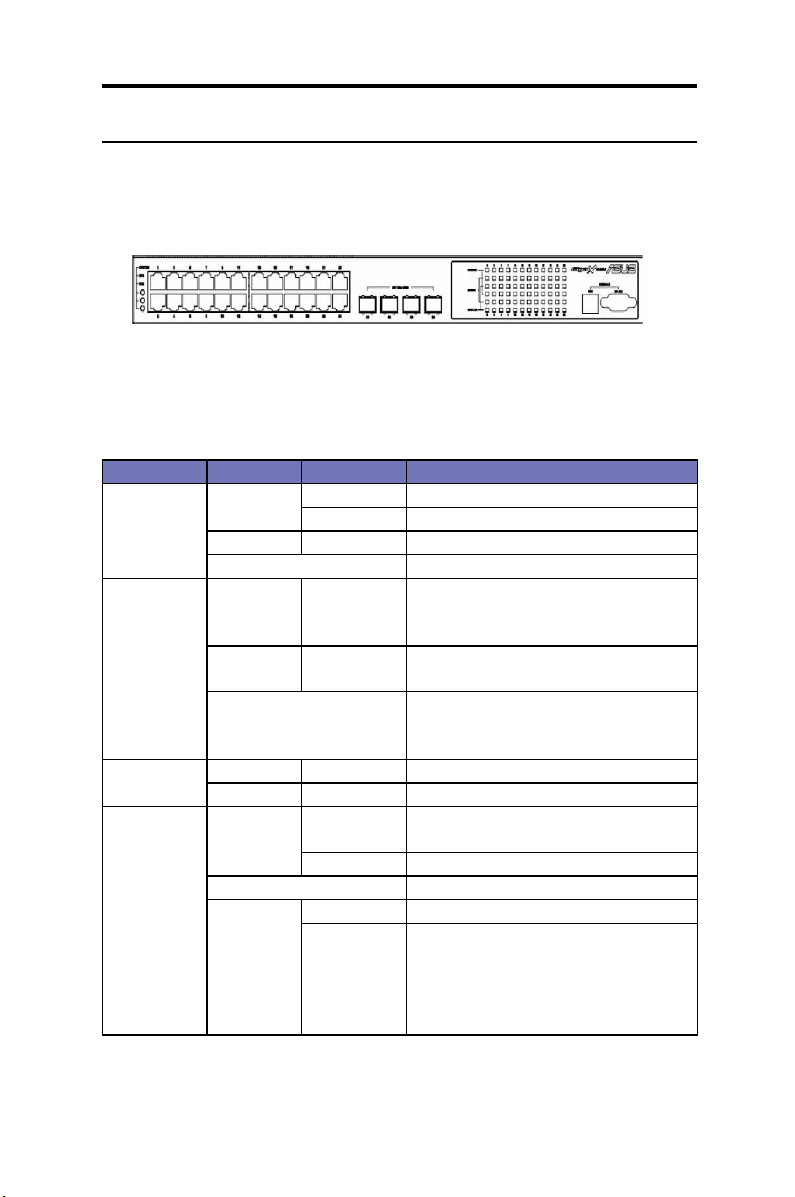
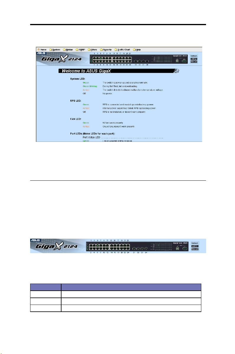
2.2 Front panel features
The front panel includes LED indicators and system console. LED indicators show the
system, RPS, fan, and port status.
Figure 2. GigaX 2124X Front panel
Table 1: Front panel labels and LEDs
Label Color Status Description
SYSTEM Green On Unit is powered on
Flashing Self-test, INIT, or downloading
Amber On Abnormal temperature or voltage
Off No power
RPS Green On The PSU is working properly and the
switch has a good redundant power
supply.
Amber On The PSU is abnormal and the switch is
powered by RPS.
Off No power at all (system LED is also
off, RPS does not work properly or not
installed (system LED on).
Fan Green On Both fans are working properly.
Amber On Both or either one of the fans stopped.
10/100/100 0
port status
Green On Link (RJ-45 or SFP) is present; port is
enabled.
Flashing Data is being transmitted/received.
Off No Ethernet link.
Amber On Port is disabled manually
Flashing Port is in block, listening or learning state
of spanning tree
Port is in Shutdown-Violation state of Port
Security
Line protocol shutdown looped-back
ASUS GigaX2124
5
Page 18
Chapter 2 - Getting to know the GigaX2124
10/100/100 0
port speed
10/100/100 0
port duplex
Green On 1000Mbps
Amber On 1000Mbps
Off 10Mbps
Green On Full-duplex mode
Amber On Half-duplex mode
Flashing Collision
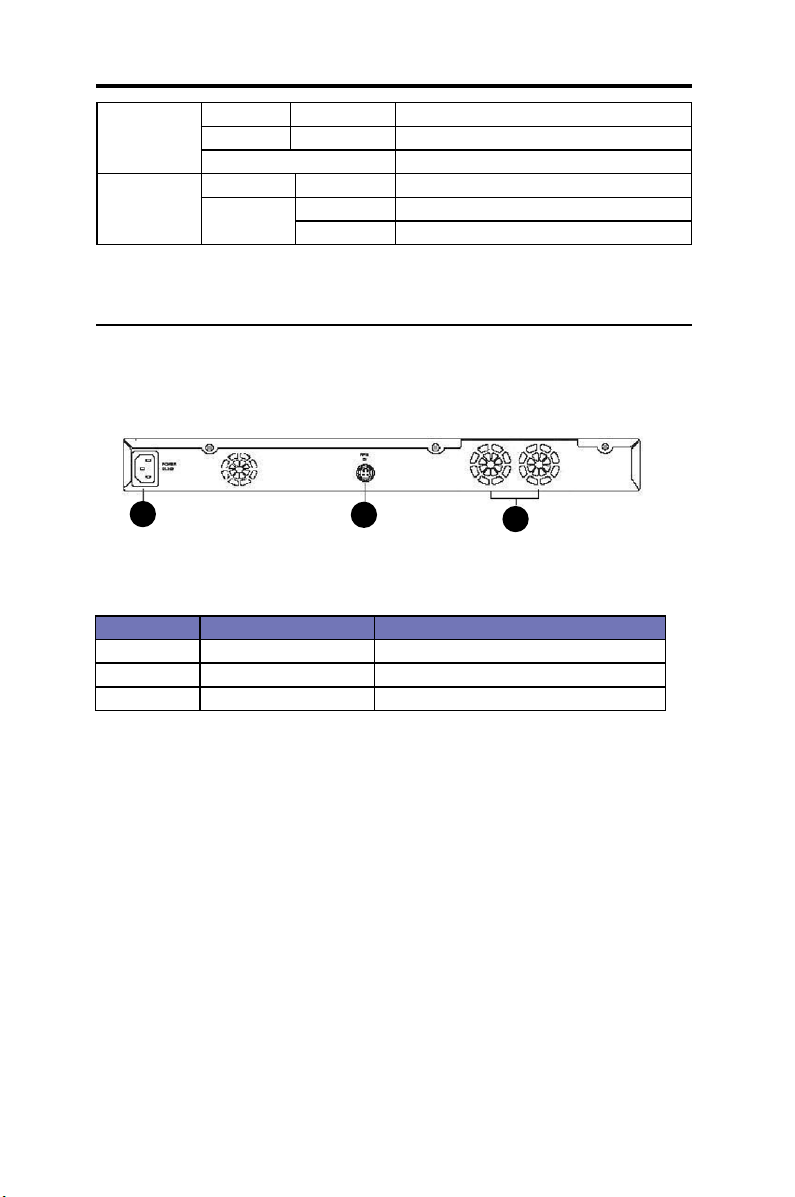
2.3 Rear panel features
The switch rear panel contains the ports and power connections.
1
Table 2: Rear panel labels
No Label Description
1 Power Connects to the supplied power cord
2 RPS Redundant power supply connector
3 FAN1 - FAN2 Replaceable system fans
2
Figure 3. Rear panel
3
6
ASUS GigaX2124
Page 19

Chapter 2 - Getting to know the GigaX2124
2.4 Technical specications
Table 3: Technical specications
Physical
Dimensions
Power
Redundant
Power Supply
(RPS)
Environmental
Ranges
Replaceable
Fans
43.5mm(H) X 444 mm(W) X 322mm(D)
Input: 100-240V AC/2.5A 50-60Hz
Consumption: <82 watts
Input: 100-240V AC/1.8A 50-60Hz
Output: 12V DC/12.5A
Operating Storage
Temperature -0 to 40oC (32 to
122oF)
Humidity 15 to 90% 0 to 95%
Altitude up to 10,000
ft (3,000m)
Dimensions: 40 x 40 x 20 mm
Voltage and Current: 12VDC, 0.13A
Speed: 8200RPM
-25 - 70oC
(-40 to 158oF)
40,000 ft (12,000m)
ASUS GigaX2124
7
Page 20

Chapter 3 - Quick Start
3 Quick Start
Th is secti on provides the basic instructions t o set u p the Gig aX
environment. Refer also to the GigaX212 4 Installation Guide.
Part 1 shows you how to install the GigaX on a at surface or on a rack.
Part 2 provides instructions to set up the hardware.
Part 3 shows you how to congure basic settings on the GigaX.
Before starting, obtain the following information from your net work
administrator:
• IP address for the switch
• Default gateway for the network
• Network mask for this network
3.1 Part 1: Installing the switch
The switch can be installed either on a at surface or on a rack.
3.1.1 Installing on a at surface
The switch should be installed on a flat surface which can support the
weight of the switches and their accessories. Attach four rubber pads on
the four indented circles located at the bottom of the switch. See illustration
below.
1
2
8
ASUS GigaX2124
3
Indented circles 1, 2, 3, & 4.
Attach rubber pads here.
4
Page 21
Chapter 3 - Quick Start
3.1.2 Installing on a rack
1. With the front panel facing out, insert the switch between the rack posts
and align the four mounting holes with that in the equipment rack.
2. Securely fasten the switch to the rack with two screws on each side.
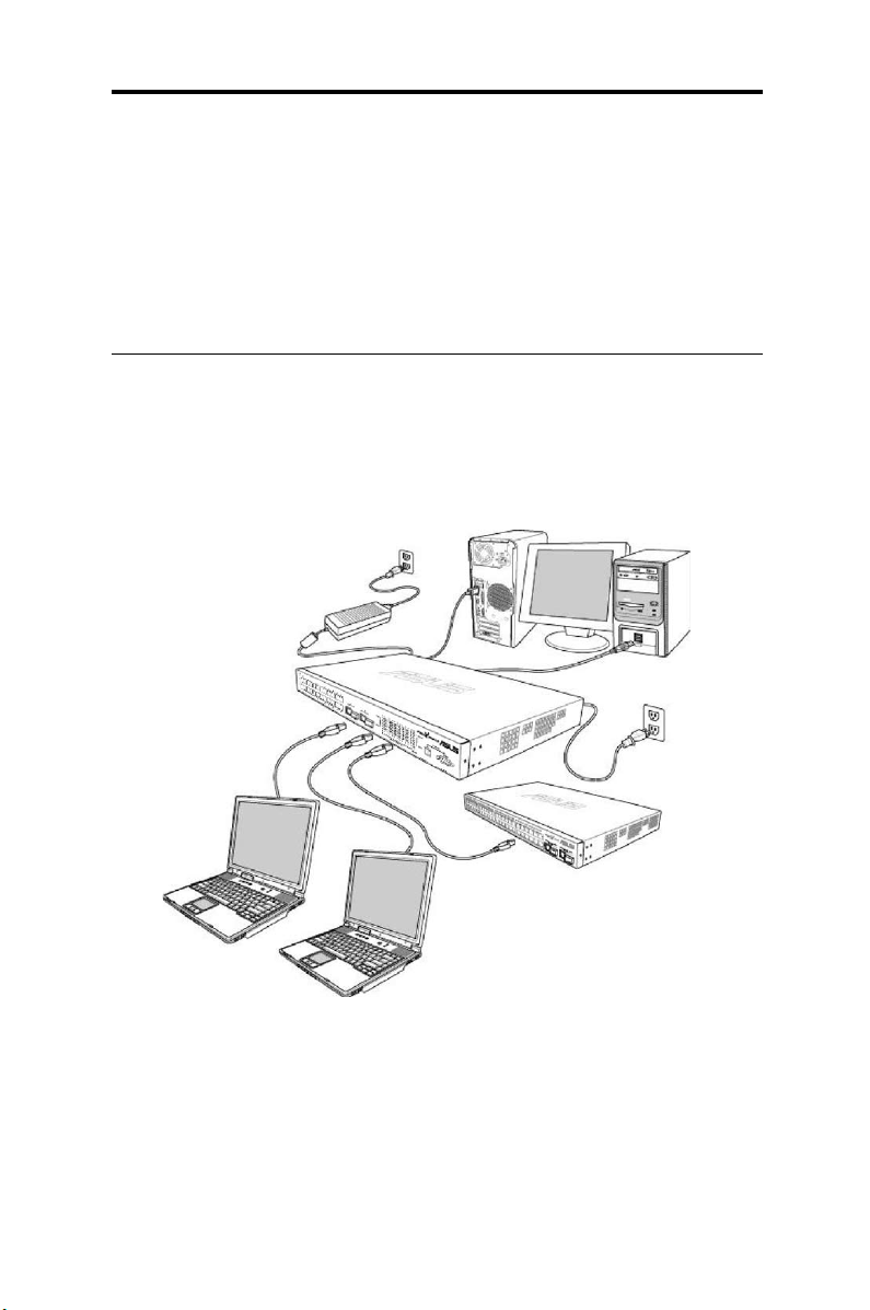
3.2 Part 2: Connecting the hardware
Connect the device to the power outlet, and to your computer and to your
network. Refer to Figure 5 for the overview of the hardware connections.
CAT 5 Ethernet cables
LAN computers
Figure 4. Overview of hardware connections
RPS
RS-232
Console Management
Expansion hubs/switch
ASUS GigaX2124
9
Page 22

Chapter 3 - Quick Start
3.2.1 Connect the console port
For console management, use an RS232 (DB9) or a USB cable to connect
the switch. If you want to use WEB interface, connect your PC to the
switch using the Ethernet cable.
3.2.2 Connect to the computers or a LAN
You can use Ethernet cable to connect computers directly to the switch
ports. You can also connect hubs/switches to the switch ports by Ethernet
cables. You can use either the crossover or straight-through Ethernet cable
to connect computers, hubs, or switches.
Use a twisted-pair Category 5 Ethernet cable to connect the 1000BASE-T
port. Otherwise, the link speed cannot reach 1Gbps.
3.2.3 Attach the RPS module
Connect your RPS module to the RPS jack and ensure the other end of
the RPS is connected to the power cord. Connect to the power cord to a
grounded power outlet.
3.2.4 Attach the power adapter
1. Connect the AC power cord to the POWER receptacle located at the
back of the switch. Plug the other end of the power cord into a wall
outlet or a power strip.
2. Check the front LED indicators. If the LEDs light up as described in
Table 4, the switch is working properly.
Table 4: LED indicators
No LED Description
1 System Solid green indicates that the device is turned on. If
this light is off, check if the power adapter is attached
to the switch and plugged into a power source.
2 Switch ports
[1] to [24]
3 RPS Solid green indicates that the device has success-
4 Fan Solid green indicates that all the fans work properly.
10
Solid green indicates that the device can communi-
cate with the LAN. If the light is ashing, it indicates
that the device is sending or receiving data from
your LAN computer.
fully installed an RPS module.
ASUS GigaX2124
Page 23

Chapter 3 - Quick Start
3.3 Part 3: Basic switch settings
After completing the hardware setup, congure the basic settings for your
switch. You can manage the switch either through the:
• Conguration Manager: The switch has a preinstalled web
application to allow you to manage the switch using Java®-enabled
IE6.0 or higher versions.
• Command Line Interface (CLI): Use console port to manage the
switch.
3.3.1 Setting up through the console port
1. Use the supplied crossover RS-232 cable to connect to the console port
located at the front of the switch. This port is a male DB-9 connector
implemented as data terminal equipment (DTE) connection. Tighten
the retaining screws on the cable to secure it to the connector. Connect
the other end of the cable to a PC running terminal emulation software
such as Hyper Terminal.
2. Use the supplied USB cable to connect to a PC. You have to install
the USB driver from the switch CD-ROM before the USB can work
properly. The USB drivers will simulate an additional COM port under
Windows ME/2000/XP OS.
3. Follow the steps below in setting up your terminal emulation software:
a) Choose the appropriate serial port number
b) Set the data baud rate to 9600
c) Set the data format to no parity, 8 data bits and 1 stop bit
d) No ow control
e) Set VT100 for emulation mode
4. After setting up the terminal, you can see the prompt “(ASUS) login” on
the terminal.
5. The default user name is “
You can change the password at any time through CLI (see section
5.31). To protect your switch from unauthorized access, you must
change the default password as soon as possible.
ASUS GigaX2124
”without password.
admin
11
Page 24

Chapter 3 - Quick Start
6. Follow these steps to assign an IP address to the switch:
a) Type “enable”.
b) Type “congure terminal”, new prompt is “ASUS(cong)#”.
c) Type “interface vlan 1”, the prompt is “ASUS (cong-if)#”.
d) Type “ip address <your ip address> <your network mask>”. For
example, if your switch IP is 192.168.1.1 and the network mask is
255.255.255.0. Then you should type “ip address
192.168.1.1/24”.
e) Type “end”, it will return to previous level with prompt “ASUS#”.
f) Type “write”, the changes will be applied and written to
conguration le.
g) Type “reboot”.
7. If the switch has to be managed across networks, then a default gateway or a static route entry is required. Follow these steps to assign a
default gateway or static route entry to the switch:
a) Entering “ASUS#”
b) Type “show running-conguration” to view current conguration. If
incorrect route entry has been set, you should type “no
ip route 0.0.0.0/0 192.168.1.254” to remove it.
c) Type “congure terminal”, new prompt is “ASUS(cong)#”.
d) Type “no ip route 0.0.0.0/0 192.168.1.254” to clear default route.
e) Type “ip route 0.0.0.0/0 192.168.1.2” to set your default route.
f) Type “end”
g) Type “write”.
12
ASUS GigaX2124
Page 25

Chapter 3 - Quick Start
Figure 5. Login and IP setup screen
3.3.2 Setting up thru the Conguration Manager
To successfully connect your PC to the switch, your PC must have a valid
IP in your network. Contact your network administrator to obtain a valid IP
for the switch. If you wish to change the default IP address of the switch,
follow section 3.3.1 to change the IP address.
1. If Java Runtime Environment is not installed on your PC, Your PC will
automatically download and install it. It means that your PC should be
able to reach the web site. If the Internet is not available, you should
prepare it on diskette and install it.
2. From any PC connected to the network that the switch can access,
open your Web browser (Internet Explorer), and type the following
URL in the address/location box, and press <
http://192.168.1.1
This is the factory default IP address of the switch.
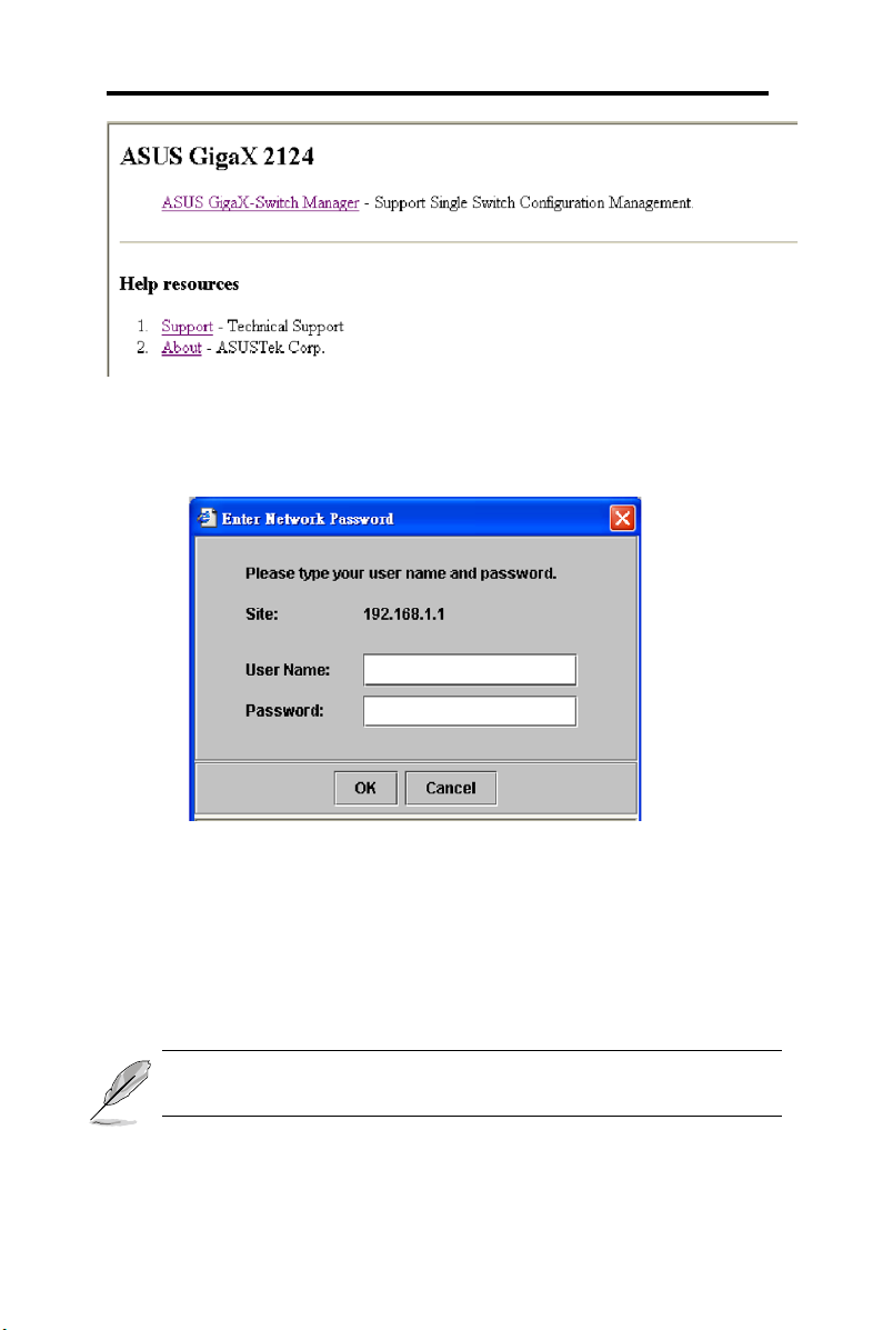
A default web page appears, as shown in Figure 6.
Then click “ASUS GigaX-Switch Manager”. A login screen appears, as
ASUS GigaX2124
Enter
>:
13
Page 26
Chapter 3 - Quick Start
Figure 6. Default web page
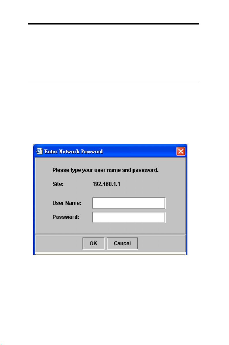
Then click “ASUS GigaX-Switch Manager”. A login screen appears, as
shown in Figure 7.
Figure 7. Login Screen
Enter your user name and password, and then click OK to enter the
Configuration Manager. Use the following defaults the first time you log
into this interface:
Default User Name: admin
Default Password: <none>
You can change the password at any time (see section 6.3.1). The browser will download java applet from the switch and it will take a little time.
14
ASUS GigaX2124
Page 27
Chapter 3 - Quick Start
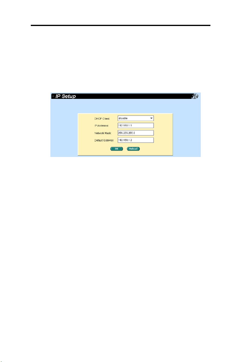
3. To setup a new IP address, click “
IP address, network mask and default gateway, then click OK.
4. When the new address is applied to the switch, the browser can no
longer update the switch status windows or retrieve any page. You
need to retype the new IP address in the address/location box, and
press <
>, then WEB link returns.
Enter
System
”, select
IP Setup
. Fill in the
Figure 8. IP Setup
ASUS GigaX2124
15
Page 28
Chapter 4 - Management with the web interface
4. Management with the web interface
The switch provides Web pages that allow switch management through
the Internet. The program is designed to work best with Microsoft Internet
Explorer® 6.0, or later versions.
4.1 Login to web user interface
1. From a PC, open your web browser, type the following in the web
address (or location) box, and press <
http://192.168.1.1
This is the factory default IP address for the switch.
A default web page appears, as show in Figure 6. Then click “ASUS
GigaX-Switch Manager”, the login screen displays, as shown in Figure 9.
Enter
>:
Figure 9. Conguration manager login screen
2. Enter your user name and password, then click .
Use the following defaults the first time you log into the program.
You can change the password at any time through CLI interface (see
section 6.3.1).
Default User Name: admin
Default Password: <none>
16
ASUS GigaX2124
Page 29
Chapter 4 - Management with the web interface
The home page appears each time you log into the program. See Figure
10.
Figure 10. Home page
4.2 Functional layout
Typical web page consists of two separate frames. The top frame has a
switch logo and front panel as shown in Figures 11. This frame remains on
the top of the browser window all the times and updates the LED status
periodically or manually by pushing “Auto” or “manual” bottoms on the
right side. See Table 4 for the LED denitions. See Table 5 for the port
color status description.
Figure 11. Top frame
Table 5: Port color description
Port Color Description
Green Ethernet link is established
Black No Ethernet link
Amber Link is present but port is disabled manually or by spanning tree
ASUS GigaX2124
17
Page 30
Chapter 4 - Management with the web interface
The menu item as shown in Figure 12 contains all the features available
for switch conguration. These features are grouped into categories, e.g.
System, Bridge, etc. You can click any of these to display a specic conguration page. (Click mouse right button to show popup menu)
18
Figure 12. Click menu item
ASUS GigaX2124
Page 31

Chapter 4 - Management with the web interface
4.2.1 Menu navigation tips
To open a specic conguration page, click the desired menu item.
4.2.2 Commonly used buttons and icons
The following table describes the function for each button and icon used in
the application.
Table 6: Commonly used buttons
Button / Icon Function
Stores any changes made on the current page.
Re-displays the current page with updated statistics or settings.
Modies the existing conguration in the system, e.g. a static route
or a lter ACL rule and etc.
Clears all input elds and waiting for new settings
Adds the existing configuration to the system, e.g. a static MAC
address or a rewall ACL rule and etc.
Modies the selected entry
Deletes the selected item, e.g. a static route or a lter ACL rule and
etc.
Query a specic status.
Detaches the feature from all ports on selection panel
Attaches the feature to all ports on selection panel
ASUS GigaX2124
19
Page 32

Chapter 4 - Management with the web interface
4.3 System
Figure 13. System menu
System page includes Management, IP Setup, Reboot, Firmware Upgrade
and other system related functions.
4.3.1 Management
The Management page contains the following information:
Model Name
: product name
MAC Address
System Name
System Contact
System Location
To save any changes and make it effective immediately, click OK. Use
Reload to refresh the settings.
20
: switch MAC address
: user assigned name to identify the system (editable)
(editable)
(editable)
Figure 14. Management page
ASUS GigaX2124
Page 33

Chapter 4 - Conguration Management
4.3.2 IP Setup
The IP Setup page contains the following information:
DHCP Client:
Enable/Disable DHCP Client for the switch.
IP Address:
Network Mask:
Default Gateway:
To save any changes and make it effective immediately, click OK. Use
Reload to refresh the settings.
IP address for the switch
Network mask for this network
Default gateway for this network
Figure 15. IP Setup page
4.3.3 Reboot
The Reboot page contains a Reboot button. Click the button reboots the
system.
Rebooting the system stops the network trafc and terminates the
Web interface connection.
4.3.4 Firmware Upgrade
The Firmware upgrade page contains the following information:
Hardware Version
Boot ROM Version
Firmware Version: Show the current running rmware version. This
number will be updated after the rmware update.
: Show the hardware revision number.
: Show the version of the boot code
ASUS GigaX2124
21
Page 34

Chapter 4 - Conguration Management
Enter the TFTP server IP address and rmware le name. Click Upgrade
to update the switch rmware. For example,
TFTP Server
: 192.168.1.155
File Name
Runtime Status: Displays the following information for each port
: Gx2124-4.1.05.00.img
Clicking the upload button loads the assigned rmware to the switch,
then reboot system after a successful rmware update. You have to re-
login to web interface again.
We strongly recommend you to backup “startup-config” before
upgrading.
Upgrading by FTP method only can be used through CLI command.
22
Figure 16. Firmware Upgrade page
ASUS GigaX2124
Page 35

Chapter 4 - Conguration Management
4.4 Physical Interface
Figure 17. Physical Interface item
The Physical Interface displays the Ethernet port status in real time. You
can congure the port in following elds in Interface Conguration window:
Port: Select the port to congure
Admin
Mode: Set the speed and duplex mode
Flow Control: Enable/Disable 802.3x ow control mechanism
Switchport Mode
Admin port VLAN
DHCP-Snoop
DHCP-Snooping: assign the selected port to be untrusted or trusted
Select the corresponding port number and congure the port setting, then
click Modify. Complete all congure actions, then click OK to make the
settings effective. Click Reload to refresh the settings to current value.
: Disable/enable the port
: Set port to trunk mode or access mode
: Assign the selected port to specic PVID
: enable/disable DHCP snooping function
port
ASUS GigaX2124
23
Page 36

Chapter 4 - Conguration Management
Figure 18. Physical Interface -1
Ethernet Link: The link is connected or not connected.
STP Status:
Duplex:
Speed:
Flow Control:
control mechanism
Oper Port VLAN:
The STP status
The duplex mode
Link speed
The setting value to enable or disable 802.3x ow
The PVID of the port
24
Figure 19. Physical Interface -2
ASUS GigaX2124
Page 37

Chapter 4 - Conguration Management
4.5 Router Reports
Figure 20. Router Reports item
This page shows all routing information including static and dynamic
learned by routing protocols.
Click
Reload
to refresh status.
Figure 21. Router Reports
ASUS GigaX2124
25
Page 38

Chapter 4 - Conguration Management
4.6 Cable Diagnosis
Figure 22. Cable Diagnosis item
To analysis the cabling plant for the common cable problems, such as
open circuits, short circuits and impedance mismatches.
Interface
: Select the interface want to detect.
Click
to start diagnose.
Query
Cable diagnosis is capable of detecting cable open or short length.
If the cable length is too shorter, the detecting result may have more
error rate.
Figure 23. Cable Diagnosis
26
ASUS GigaX2124
Page 39

Chapter 4 - Conguration Management
4.7 Save Conguration
Figure 24. Save Conguration item
To save conguration permanently, you have to click
Sometimes you may want to reset the switch conguration, you can click
Reload
system reboot will follow this restoration process.
to reset the configuration file to factory default. Of course, a
You will lose all the congurations when you choose to restore the
factory default congurations.
Save
.
Figure 25. Save Conguration
ASUS GigaX2124
27
Page 40

Chapter 4 - Conguration Management
4.8 Bridge
Figure 26. Bridge menu
The Bridge page group contains most layer 2 configurations, like link
aggregation, STP, etc.
4.8.1 Spanning tree
The page congures three types of Spanning Tree Protocol.
4.8.1.1 STP Status
The “STP Status” can disable or enable STP. There are three modes STP,
RSTP and MSTP can be enabled. If MSTP is enabled, the following four
attributes are enabled at the same time:
Region Name
Revision
Instance ID
to map multiple VLANs into a single STP instance.
VLAN Group
to the given instance
28
: An alphanumeric conguration name
: A conguration revision number
: A STP instance, you can congure MSTP on your switch
: A group associates each of the potential 4094 VLANs
ASUS GigaX2124
Page 41

Chapter 4 - Conguration Management
Figure 27. Spanning tree – STP Status
4.8.1.2 Current Roots
It shows the information of current root bridge which include
• Instance ID
•
The VLAN group belong to which instance ID
•
MAC Address of root bridge
•
Priority of root bridge
•
Maximum age of root bridge
•
Hello timer of root bridge
•
Forwarding delay timer of root bridge
•
Path cost of root bridge
•
Root port of the bridge
ASUS GigaX2124
29
Page 42

Chapter 4 - Conguration Management
Figure 28. Spanning tree – Current Roots
4.8.1.3 Bridge Parameters
The spanning-tree parameters of BPDU transmission can be congured on
this panel:
Priority: The switch priority in the LAN
Max Age: A timeout value to be used by all Bridges in the LAN
Hello Time: The interval of generation of conguration BPDU
Forward Delay: A timeout value to be used by all bridges in the LAN
Transmission Limit: The minimum interval (seconds) between the
transmission of BPDUs
30
Figure 29. Spanning tree – Bridge Parameters
ASUS GigaX2124
Page 43

Chapter 4 - Conguration Management
4.8.1.4 Port Parameters
This contains a display window to show the current conguration for each
port. You can select a port then edit it. Click
setting for spanning-tree. The following elds are available:
to change the port
Modify
Instance ID (MSTP Only)
congure MSTP on your switch to map multiple VLANs into a single
STP instance.
Path Cost: The valid value is from 1 to 200000000. The higher cost is
more likely to be blocked by STP if a network loop is detected.
Priority: Set the port priority in the switch. Low numeric value
indicates a high priority. The port with lower priority is more likely to be
blocked by STP if a network loop is detected. The valid value is from 0
to 240.
Link Type: by default, the link type is determined from the duplex
mode of the interface: a full-duplex port is considered to have a pointto-point connection; a half-duplex port is considered to have a shared
connection.
Edge Port: An edge port is the same as a Port Fast-enabled port, and
you should enable it only on ports that connect to a single end station.
Click
settings to current value.
to make the settings effective. Click
OK
: A spanning-tree instance, you can
Reload
to refresh the
Figure 30. Spanning tree – Port Parameters
ASUS GigaX2124
31
Page 44

Chapter 4 - Conguration Management
4.8.1.5 Runtime Status
It shows the current status for each port.
Figure 31. Spanning tree – RunTime Status
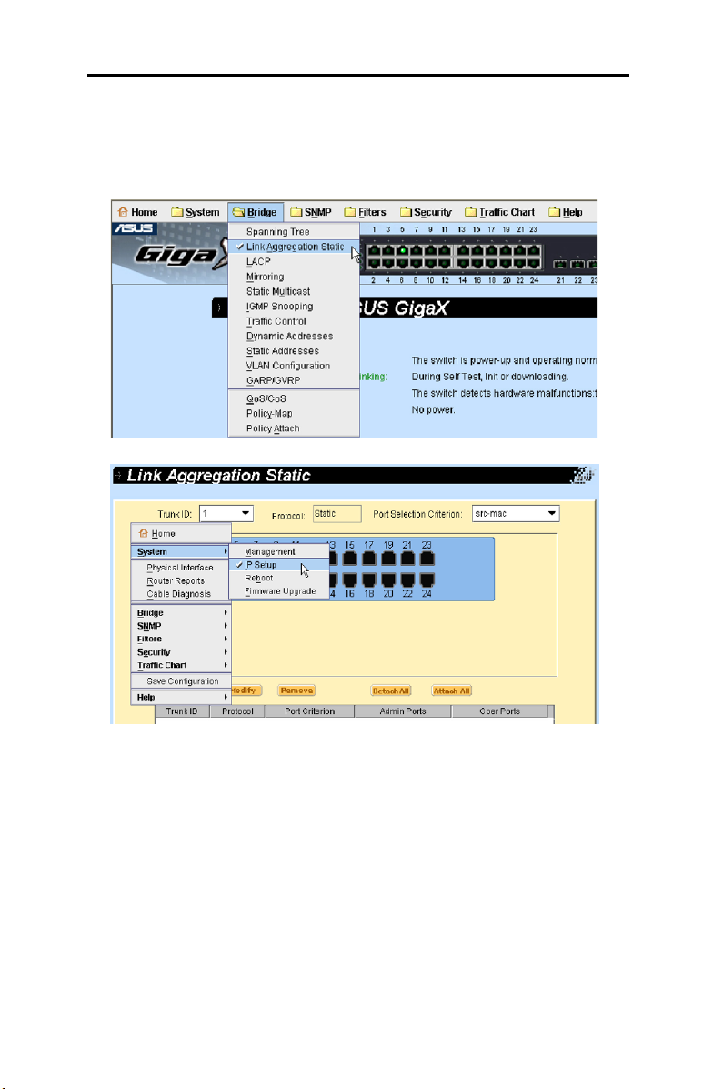
4.8.2 Link aggregation static
The page congures the link aggregation static group (port trunking). The
maximum group is 8 and up to 8 ports per group.
Trunk ID: A number to identify the trunk group
Protocol: Show the state of the link aggregation group. For the page
is static.
Port Selection Criterion: The algorithm to distribute packets among
the ports of the link aggregation group according to source MAC
address, destination MAC address, source and destination MAC
address, source IP address, destination IP address, or source and
destination IP address.
Port
Click OK to make the settings effective. Click
settings to current value.
You have to check the runtime link speed and duplex mode to make sure
the trunk is physically active. Go to Physical Interface and check the link
mode in the Runtime Status window for the trunk ports. If all the trunk
32
: These port icons are listed the same way as on the front panel.
You have to click the icon to select the group members. The port can
be removed from the group by clicking the selected port again.
Reload
ASUS GigaX2124
to refresh the
Page 45

Chapter 4 - Conguration Management
members are in the same speed and full duplex mode, then the trunk
group will set up successfully. If one of the members is not in the same
speed or full duplex mode, the trunk will not set correctly. Check the link
partner and change the settings to have the same speed and full duplex
mode for all the members of your trunk group.
All the ports in the link aggregation group MUST operate in fullduplex mode at the same speed.
All the ports in the link aggregation group MUST be congured in
auto-negotiation mode or full duplex mode. This conguration will
make the full duplex link possible. If you set the ports in full duplex
force mode, then the link partner MUST have the same setting.
Otherwise the link aggregation could operate abnormally.
All the ports in the link aggregation group MUST have the same
VLAN setting.
All the ports in the link aggregation group are treated as a single
logical link. That is, if any member changes an attribute, the others
will change also. For example, a trunk group consists of port 1 and
2. If the VLAN of port 1 changes, the VLAN of port 2 also changes
with port 1.
Figure 32. Link aggregation
ASUS GigaX2124
33
Page 46

Chapter 4 - Conguration Management
4.8.3 LACP
The page configures the LACP group (port trunking) and shows LACP
running information. The maximum group is 8 and up to 8 ports per group.
The rst part congures LACP group.
Trunk ID: A number to identify the trunk group
Protocol: Show the state of the link aggregation group. For the page
is LACP.
Port Selection Criterion: The algorithm to distribute packets among
the ports of the link aggregation group according to source MAC
address, destination MAC address, source and destination MAC
address, source IP address, destination IP address, or source and
destination IP address.
Port: These port icons are listed the same way as on the front panel.
You have to click the icon to select the group members. The port can
be removed from the group by clicking the selected port again.
Admin Ports: Show port members the user congured
Oper Ports: Show real operation ports
Click OK to make the settings effective. Click
settings to current value.
Figure 33. LACP – mode
34
ASUS GigaX2124
Reload
to refresh the
Page 47

Chapter 4 - Conguration Management
The second part shows LACP running information for each Trunk ID.
Figure 34. LACP – LACP Information
The last part shows LACP running information for each operation port
interface.
Figure 35. LACP - Interface
ASUS GigaX2124
35
Page 48

Chapter 4 - Conguration Management
4.8.4 Mirroring
Mirroring, together with a network traffic analyzer, helps you monitor
network trafcs. You can monitor the selected ports for egress or ingress
packets.
Mirror Mode
group.
Stack ID: Select stack ID. In standalone mode, it is always 1.
Session: Two sessions for selection. Session 1 is for port 1 ~ 12 and
Session 2 is for port 13~24.
Monitor Port: Receive the copies of all the trafcs in the selected
mirrored ports.
Port: Select the mirrored port from selection panel. The selected port
can be mirrored for Ingress, Egress or Both of trafc.
The monitor port can not belong to any link aggregation group.
The monitor port can not operate as a normal switch port. It does not
switch packets or do address learning.
Click OK to make the settings effective. Click
settings to current value.
: Enable or disable the mirror function for the selected
Reload
to refresh the
36
Figure 36. Mirroring
ASUS GigaX2124
Page 49

Chapter 4 - Conguration Management
4.8.5 Static Multicast
This page can add multicast addresses into the multicast table. The switch
can hold up to 256 multicast entries. All the ports in the group will forward
the specied multicast packets to other ports in the group.
VLAN: Input the VLAN group, it is VLAN-based feature
MAC Address: Assign the multicast address
Port: Select the port from selection panel. Or select an existing group
address from list panel to display
Click OK to make the settings effective. Click
settings to current value.
Figure 37. Static Multicast
Reload
to refresh the
ASUS GigaX2124
37
Page 50

Chapter 4 - Conguration Management
4.8.6 IGMP snooping
IGMP snooping helps reduce the multicast trafcs on the network by allowing the IGMP snooping function to be turned on or off.
The rst part provides the following settings.
Enable IGMP Snoop ing
existing VLAN interfaces. By default, IGMP snooping is globally
disabled on the switch. When globally enabled or disabled, it is also
enabled or disabled in all existing VLAN interfaces.
If global snooping is disabled, you cannot enable VLAN snooping. If global
snooping is enabled, you can enable or disable VLAN snooping.
Last Member Query Interval: Without Immediate Leave, when
the switch receives an IGMP leave message from a subscriber on
a receiver port, it sends out an IGMP query on that port and waits
for IGMP group membership reports. If no reports are received in a
congured time period, the receiver port is removed from multicast
group membership.
The second part provides the following settings.
: Globally ena ble IGMP snooping in all
Status
Immediate leave: When you enable IGMP Immediate-Leave
(However, if the static entries occupy all 256 spaces, the IGMP snoop does
not work normally. The switch only allows 256-layer 2 multicast groups.)
Click OK to make the settings effective. Click
settings to current value.
38
: If global snooping is enabled, you can enable or disable
VLAN snooping.
processing, the switch immediately removes a port when it detects
an IGMP version 2 leave message on that port. You should use the
Immediate-Leave feature only when there is a single host present on
every port in the VLAN. Immediate Leave is supported with only IGMP
version 2 hosts.
Reload
ASUS GigaX2124
to refresh the
Page 51

Chapter 4 - Conguration Management
Figure 38. IGMP Snooping – Setting
Multicast Group shows all multicast group information, including static
congured and dynamic learned.
Figure 39. IGMP Snooping – Multicast Group
ASUS GigaX2124
39
Page 52

Chapter 4 - Conguration Management
4.8.7 Trafc control
Trafc control prevents the switch bandwidth from ooding packets including broadcast packets, multicast packets and the unicast packets because
of destination address lookup failure. The limit number is a threshold to
limit the total number of the checked type packets. For example, if broad-
cast and multicast are enabled, the total trafc amount for those two types
will not exceed the limit value.
B ro adcast
broadcast packets
Multicast
packets
Destination Lookup Failure
rate limit of destination lookup failure packets
Selects an interface and assigns desirable settings, then click Modify.
Click OK to make the settings effective. Click Reload to refresh the settings to current value.
: Ch oo se d is ab le o r in pu t a numb er for r ate li mit of
: Choose disable or input a number for rate limit of multicast
: Choose disable or input a number for
40
Figure 40. Trafc Control
ASUS GigaX2124
Page 53

Chapter 4 - Conguration Management
4.8.8 Dynamic addresses
This page displays the result of dynamic MAC address lookup by port,
VLAN ID, or specified MAC address. The dynamic address is the MAC
address learned by switch, it will age out from the address table if the
address is not learned again during the age time. User can set the age
time by entering a valid number from 10 to 1,000,000 in seconds. Click
to make the settings effective. Click
OK
current value.
You can look up MAC addresses by checking the port, VLAN ID, or/and
MAC address, then click
of the query.
. The address window will display the result
Query
Reload
to refresh the settings to
Figure 41. Dynamic Addresses
4.8.9 Static addresses
You can add a MAC address into the switch address table. The MAC address added by this way will not age out from the address table. We call it
static address.
MAC Address
VLAN ID
Stack ID
Port Selection
: Enter the MAC address
: Enter the VLAN ID that the MAC belongs
: Select stack ID. In standalone mode, it is always 1.
: Select the port, which the MAC belongs
ASUS GigaX2124
41
Page 54

Chapter 4 - Conguration Management
Click Add when you create a new static MAC address by the above information. Then you will see the new added entry shows in the address window. You can remove the existed address by selecting the entry with the
mouse, then click Remove. The Modify button updates the existed MAC
address entries. Click OK to make the settings effective. Click Reload to
refresh the settings to current value.
Figure 42. Static Addresses
4.8.10 VLAN Conguration
You can set up to 3000 VLAN groups and show VLAN group in this
page. VLAN1 is a default VLAN, which is created by system. It cannot be
removed at all. This feature prevents the switch from malfunctions. You
can remove any existed VLAN except the VLAN1.
You can assign the port to be a tagged port or an untagged port by toggling
the port button. There are three types of button in port selection panel:
“P” type: Set the port default VLAN ID. If a port receives untagged
packets, these packets will be considered as the default VLAN group.
“U” type: Untagged port that will remove VLAN tags from the
transmitted packets.
“T” type: All packets transmitted from this port will be tagged.
“blank” type: This port is not a member of the VLAN group.
If one untagged port belongs to two or more VLAN groups at the same
time, it will confuse the switch and cause ooding trafcs. To prevent it, the
switch only allows one untagged port belongs to one VLAN at the same
42
ASUS GigaX2124
Page 55

Chapter 4 - Conguration Management
time.
If you want to assign an untagged port from one VLAN to another, you
have to remove it from the original VLAN, or change it to be tagged in the
original VLAN rst.
VLAN ID: this eld requires user to enter the VLAN ID when a new
VLAN is created
Name: this eld requires user to assign a name for the VLAN
If you want to add a ne w VLAN group, must click
conguring settings, click
Click OK to make the settings effective. Click
settings to current value.
Add
.
Reload
Figure 43. VLAN Conguration
fi rst. After
New
to refresh the
ASUS GigaX2124
43
Page 56

Chapter 4 - Conguration Management
4.8.11 GVRP
Generic Attribute Registration Protocol (GARP) VLAN Registration Protocol
(GVRP) is an application dened in the IEEE 802.1Q standard that allows
for the control of VLANs.
GVRP will run only on 802.1Q trunk ports and is used primarily to prune
traffic from VLANs that does not need to be passed between trunking
switches. There are some parameters to congure GVRP:
GVRP Enable
must rst enable GVRP on the switch before you can congure the
802.1Q ports for GVRP operation.
Port Mode: Enables/Disables GVRP on the individual 802.1Q trunk
port. GVRP must be congured on both sides of the trunk to work
correctly.
Registration: By default GVRP ports are in normal registration mode.
These ports use GVRP join messages from neighboring switches to
prune the VLANs running across the 802.1Q trunk link. If the device
on the other side is not capable of sending GVRP messages, or if you
do not want to allow the switch to prune any of the VLANs, use the
xed mode. Fixed mode ports will forward for all VLANs that exist in
the switch database. Ports in forbidden mode forward only for VLAN
1.
Click OK to make the settings effective. Click
settings to current value.
: By default GVRP is not enabled for the switch. You
Reload
to refresh the
44
Figure 44. GVRP Mode
ASUS GigaX2124
Page 57

Chapter 4 - Conguration Management
Edit the following attributes as needed:
Joint Timer: Set value in centiseconds.
Leave Timer: Set value in centiseconds.
LeaveAll Timer: Set value in centiseconds.
Click OK to make the settings effective. Click
settings to current value.
Reload
to refresh the
Figure 45. GARP Timer
4.8.12 QoS and CoS
4.8.12.1 802.1p Priority
Eight egress queues on all switch ports. These queues can either be
congured with the Weighted Round Robin (WRR) scheduling algorithm or
congured with one queue as a strict priority queue and the other queues
for WRR. The strict priority queue must be empty before the other queues
are serviced. You can use the strict priority queue for mission-critical and
time-sensitive trafc. There are three options:
First Come First Service: The rst come frame has the highest
priority
High Priority First
: Packet’s priority depends on its CoS value
ASUS GigaX2124
45
Page 58

Chapter 4 - Conguration Management
Weighted Round Robin (WRR): If WRR scheduling algorithm is
enabled, the ratio of the weights is the ratio of frequency in which the
WRR scheduler de-queues packets from each queue.
Click OK to make the settings effective. Click
settings to current value.
Figure 46. 802.1p Priority
Reload
to refresh the
4.8.12.2 CoS queue mapping
The switch supports eight egress queues for each port with a strict priority
scheduler. That is, each CoS value can map into one of the eight queues.
The queue eight has the highest priority to transmit the packets. Click
to make the settings effective. Click
OK
current value.
The CoS values range from 0 for low priority to 7 for high priority.
Reload
to refresh the settings to
46
ASUS GigaX2124
Page 59

Chapter 4 - Conguration Management
Figure 47. CoS Queue Mapping
4.8.12.3 QoS Bandwidth
Some VLAN tag related field settings for each port are included in this
page. It includes:
Port: Select a port from list window to congure
Ingress Bandwidth: Maximum ingress bandwidth for selected port
Default CoS: Every untagged packet received from this port will be
assigned to this CoS value in the VLAN tagged
Click
Modify
make the settings effective. Click
value.
to change the content in the port list window. Click OK to
Reload
ASUS GigaX2124
to refresh the settings to current
47
Page 60

Chapter 4 - Conguration Management
Figure 48. QoS Bandwidth
4.8.13 Policy Map
Policy Map offers the capability that user can change the priority of
incoming, transmitting packets and dropping packets when over-loading.
4.8.13.1 Policy Map Setting
Give a name for policy map set then click
conguration permanently or
before editing the rules of the policy set.
Click
Second, click
the map set. You have to follow the rules to make a valid policy map set.
48
a policy map set to select the set you want to edit or remove.
Edit
Remove
Reload
to enter the rule setting page, or click to remove
Figure 49. Policy Map Set
ASUS GigaX2124
to refresh the page. Please click
. Click OK to save the
Add
OK
Page 61

Chapter 4 - Conguration Management
Provide four criteria and three take actions for rule setting:
Match Criterion: Chose one of IP DSCP with range, IP Precedence
with range, ACL name with an exist lter access-list, None for criteria.
Prole Action: Chose one of Police Drop, Police High-Drop, None
for action.
In-Prole Action: Chose Cos Override with COS value, Mark IP
SCP, Mark IP Precedence or None to take action on incoming
packets.
Out-Prole Action: Choose Drop, IP DSCP or None for transmitting
packets and also can set Rate and Burst Size.
Figure 50. Policy Map Class
4.8.13.2 Policy Attach
A policy map set is idle if you did not attach it to any port. Use the Policy
Attach page to attach a lter set to ingress ports.
Chose an exist policy map set, then click ports want to apply.
Click OK to make the settings effective. Click
settings to current value.
ASUS GigaX2124
Reload
to refresh the
49
Page 62

Chapter 4 - Conguration Management
Figure 51. Policy Attach
4.9 SNMP
Figure 52. SNMP menu
This group offers the SNMP conguration including Community Table, Host
Table, and Trap Setting.
4.9.1 Community Host Table
You can type host IP addresses with different community names and
specify whether the community has the privilege to do set action (ro – read
only, rw – read and write) by selecting the Type. Click OK to make the
settings effective. Click
50
to refresh the settings to current value.
Reload
ASUS GigaX2124
Page 63

Chapter 4 - Conguration Management
Figure 53. Community Host Table
4.9.2 Trap Setting
By setting trap destination IP addresses and community names, you can
enable SNMP trap function to send trap packets in different versions (v1 or
v2).
Click OK to make the settings effective. Click
settings to current value.
Reload
to refresh the
Figure 54. Trap Setting
ASUS GigaX2124
51
Page 64

Chapter 4 - Conguration Management
4.9.3 SNMPv3 VGU Table
There’r e t wo article s p resenting the new sec urity feat ures defin ed
by SNMPv3. The User-based Security Model (USM), which provides
authentication, encryption, and decryption of SNMPv3 packets. The Viewbased Access Control Model (VACM), which provides access control. The
followings are three related pages. Click OK to make the settings effective.
Click
Reload
4.9.3.1 Views
VACM View is used to view the information of SNMPV3 VACM Group.
to refresh the settings to current value.
View Name
View Subtree: Enter the View Subtree that the View belongs. The
Subtree is the Oid to match the Oid in the SNMPv3 message. The
match is good when the subtree is shorter than the Oid in the SNMPv3
message.
View Type: Chose the View Type that the View belongs. Included
or Excluded when View Subtree matches the Oid in the SNMPv3
message.
Click
Add
information. Then you will see the new added entry shows in the view
window. You can remove the existed views by selecting the entry with the
mouse, then click
View entries. Click OK to make the settings effective. Click
refresh the settings to current value.
: Enter the security group name.
wh en you create a new VACM Vi ew entry by the above
Remove
. The
button updates the existed VACM
Modify
Reload
to
52
ASUS GigaX2124
Page 65

Chapter 4 - Conguration Management
Figure 55. SNMPv3 VGU Table - Views
4.9.3.2 Groups
VACM Group is used to configure the information of SNMPV3 VACM
Group.
Group Name: Enter the security group name.
Security Model
belongs. Any is suitable for v1, v2, v3. USM is SNMPv3 related.
Security level
belongs. Only NoAuthNoPriv, AuthNopriv, AuthPriv can be chosen.
Read View Name: Chose the Read View Name that the Group
belongs. The related SNMP messages are Get,GetNext,GetBulk.
Write View Name
belongs. The related SNMP message is Set.
Notify View Name: Chose the Notify View Name that the Group
belongs. The related SNMP messages are Trap,Report.
Click
information. Then you will see the new added entry shows in the group
window. You can remove the existed group by selecting the entry with the
mouse, then click
Group entries. Click OK to make the settings effective. Click
refresh the settings to current value.
when you create a new VACM group entry by the above
Add
: Chose the Security Model Name that the Group
: Chose the Security level Name that the Group
: Chose the Write View Name that the Group
Remove
. The
ASUS GigaX2124
button updates the existed VACM
Modify
Reload
to
53
Page 66

Chapter 4 - Conguration Management
Figure 56. SNMPv3 VGU - Groups
4.9.3.2 Users
USM User is used to congure the information of SNMPV3 USM User.
User Name
Group Name
Security level
belongs. Only NoAuthNoPriv, AuthNopriv, AuthPriv can be chosen.
Auth Algorithm
Security Group belong. Only MD5, SHA can be chosen.
Auth Password
The password needs at least 8 characters or digits.
Priv Algorithm
Security Group belong. Only DES can be chosen.
Priv Password
The password needs at least 8 characters or digits.
Cl ic k
Ad d
information. Then you will see the new added entry shows in the User
window. You can remove the existed User by selecting the entry with the
mouse, then click
54
: User name of a specic security group
: Chose the security group name
: Chose the Security level Name that the Group
: Chose the Auth Protocol that SNMP User and
: Enter the password that the Auth Protocol belongs.
: Chose the Priv Protocol that SNMP User and
: Enter the password that the Priv Protocol belongs.
when you cr ea te a new USM User en tr y by the above
Remove
. The button updates the existed USM User
ASUS GigaX2124
Page 67

Chapter 4 - Conguration Management
entries. Click OK to make the settings effective. Click
the settings to current value.
Figure 57. SNMPv3 VGU - Users
4.10 Filters
Reload
to refresh
Figure 58. Filters menu
The switch can filter certain traffic types according to packet header
information from Layer 2 to Layer 4. Each lter set includes a couple of
rules. You have to attach the filter set to certain ports to make the filter
work.
4.10.1 Filter set
The switch denes two modes of rules, one is MAC mode and the other is
IP mode. Only the same mode of rules can bundle together to form a lter
set. Each mode has different elds to congure. For example, you can use
IP mode rule to lter FTP packets.
You can check the MAC Filter and give a Name then add it. You also can
check the IP Filter and give an ID/Name. The difference between IP Filter
Standard and IP Filter Extended is Extended mode can set more complex
ASUS GigaX2124
55
Page 68

Chapter 4 - Conguration Management
rules. After setting lter mode and name, click
Click OK to save the conguration permanently or
page. Please click OK before editing the rules of the lter set.
Click a lter set to select the set you want to edit or remove. Second, click
to enter the rule page, or click
Edit
have to follow the rules to make a valid lter set.
One set consists of a type of rules. The rules having the same fields to
lter packets belong to one type. For example, two rules lter packets with
two destination IP addresses, they are the same type. But a rule ltering
source IP address does not belong to the same type.
The count of rule types is not unlimited. Turn on some special switch
functions may decrease the count. If no free type is available, the system
will show warning message and the rule will not be set.
Reload
.
Add
Reload
to remove the lter set. You
to refresh the
Figure 59. Filter Set
The Filter Rule page provides options for rule modes, one is MAC rule and
the other is IP rule. In MAC rule, users can set MAC address, VLAN ID and
COS value. If you did not enter the MAC address in the blank box, it means
the rule don’t care the MAC value. In IP rule setup, you can enter any of
the 5 types: source IP, destination IP, protocol, source application port
and destination application port. The protocol led offers TCP, UDP, ICMP
and Any for selection. The
dropped or forwarding when it matches the rule. If a packet matches two
rules with different action, the packet will follow the rule showed rst in the
rule list.
56
eld determines if the packet should be
Action
ASUS GigaX2124
Page 69

Chapter 4 - Conguration Management
Figure 60. Filter rule in MAC mode
Figure 61. Filter rule in IP mode
Two examples tell us about how to use Wildcard and IP to represent IP
host or IP group:
1. Assign a dedicated IP, Type = subnet, IP = 10.10.1.2, Wildcard =
0.0.0.0
2. Assign a subnet (a group of IP), Type = subnet, IP = 10.10.1.0,
Wildcard = 0.0.0.255
ASUS GigaX2124
57
Page 70

Chapter 4 - Conguration Management
4.10.2 Filter Attach
A lter set is idle if you did not attach it to any ingress port. Use the Filter
Attach page to attach a lter set to ingress ports.
Click OK to make the settings effective. Click
settings to current value.
To attach a lter set to ports:
Reload
to refresh the
Filter ID/Name
Attach to all ports
Attach to certain ports
Detach from all ports
You may not detach certain ports after issuing an “Attach All”
command. If you wish to detach ports, use the “Detach All”
command.
Once the lter set is attached to the ingress ports, it will lter the packets
according to the ingress port and the packet fields in the rules. For
example, a set with a single rule to filter out destination MAC address
00:10:20:30:40:50 is attached to ingress port 3. A packet with destination
MAC 00:10:20:30:40:50 from port 3 is not permitted.
: Select a lter name or ID.
: The lter set applies to all the ports of the system
: Specify the ingress ports to be applied
: Remove all the lters from the attached ports
58
Figure 62. Filter Attach
ASUS GigaX2124
Page 71

Chapter 4 - Conguration Management
4.11 Security
Figure 63. Security menu
The s witch supports th e 802.1x port-b as ed security fea ture. Only
authorized hosts are allowed to access the switch port. Traffic will be
blocked from unauthenticated host. Authentication can be provided via a
RADIUS server or the local database in the switch.
The switch also supports dynamic VALN assignment through 802.1x
authentication process. The VLAN information for the users/ports should
be configured in the authentication server properly before enabling this
feature.
4.11.1 Port Access Control
Port Access Control is used to configure various 802.1x parameters.
802.1x uses either RADIUS server or local database to authenticate port
users.
The rst part is the Bridge (Global) settings:
System-Auth-Control
Authentication Method
authenticate the port user.
The second part is the port settings. Please click
with the modications:
Port
Host Mode
: Specify which port to congure from port list window.
: If multi-host, ALL hosts connected to the selected
port are allowed to use the port if ONE of the hosts passed the
authentication. If single-host, only ONE host is allowed to use the port.
: Check it to enable the authentication
: RADIUS or Local database can be used to
Modify
ASUS GigaX2124
when you’re done
59
Page 72

Chapter 4 - Conguration Management
Authentication Control: If force-authorized is selected, the selected
port is forced authorized. Thus, trafc from all hosts is allowed to
pass. Otherwise, if force-unauthorized is selected, the selected port is
blocked and no trafc can go through. If auto is selected, the behavior
of the selected port is controlled by 802.1x protocol. All ports should
be set to Auto under normal conditions.
Reauthentication
the port user again when the re-authentication time is up.
ReAuthentication Time
time period the switch uses to re-send authentication request to the
port user (see above).
Quiet Period
period before sending another authentication request to the port user.
Guest Vlan
capable.
: Once enabled, the switch will try to authenticate
: If Reauthentication is enabled, this is the
: If authentication failed, the switch waits upon this time
: Specify a guest VLAN to clients that are not 802.1x-
Click OK to make the settings effective. Click
settings to current value.
Figure 64. Port Access Control
Modify
to refresh the
60
ASUS GigaX2124
Page 73

Chapter 4 - Conguration Management
4.11.2 Dial-in User
Dial-in User is used to dene users in the local database of the switch.
User Name
Password
Conrm Password
Vlan ID
clients.
Please click
the modications. Click
user.
Click OK to make the settings effective. Click
settings to current value.
: New user name.
: Password for the new user.
: Enter the password again.
: Specify the VLAN ID assigned to the 802.1x-authenticated
to add the new user. Click
Add
Remove
when you want to remove the selected
Modify
when you’re done with
Reload
to refresh the
Figure 65. Dial-in user
ASUS GigaX2124
61
Page 74

Chapter 4 - Conguration Management
4.11.3 RADIUS
In order to use external RADIUS server, the following parameters are
required to be setup:
Authentication Primary/Secondary Server IP
the primary/secondary RADIUS server.
Authentication Primary/Secondary Server Port
for the primary/secondary RADIUS server is listening to.
Authentication Primary/Secondary Server Key
communications between GigaX and the primary/secondary RADIUS
server.
Conrm Authentication Key
The VLAN of the RADIUS server connected to the switch must be
the same as the VLAN of the system management interface.
Click OK to make the settings effective. Click
settings to current value.
: Re-type the key entered above.
: The IP address of
: The port number
: The key is used for
Reload
to refresh the
62
Figure 66. RADIUS
ASUS GigaX2124
Page 75

Chapter 4 - Conguration Management
4.11.4 Port Security
The switch also supports port security feature. It enables a system’s
administrator to control who can connect to their network. You can use
the port security feature to restrict input to an interface by limiting and
identifying MAC addressed of the stations allowed to access the port.
When you assign secure MAC addresses to a secure port, the port does
not forward with source addresses outside the group of dened addresses.
This decreases the possibility that a non-authorized device can use our
network for malicious purposes.
4.11.4.1 Port Conguration
The page is used to congure port security conguration.
First, you must select a port by clicking it from the following table. Then,
begin to set the port conguration. Click
the modications:
when setting done with
Modify
Admin
Violation Mode
Max MAC Address
Aging Time
Aging Type
: Enable or disable port security feature.
: It decides the port behavior when security violation
happens. If shutdown is selected, the port becomes blocking state
and system logs a syslog message, and increments the violation
counter. If restrict is selected, a syslog message is logged, and the
violation counter increments. If protect is selected, you are not notied
that a security violation has occurred.
: The maximum number of secure MAC addresses
on this port. It is between 1 and 256 and the total number in the
system is 1024.
: The aging time for this port. After the expiration of
the time, the corresponding dynamic secure MAC address will be
removed from secure MAC address table. The valid range is 0 to
1440 (min). If the time is equal to 0, the aging mechanism is disabled
for this port.
: The aging type determines the action when the secure
MAC addresses are aged out. If absolute is selected, the secure
addresses on the port are deleted after the specied aging time. If
inactivity is selected, the secure addresses in the port are deleted only
if there is no data trafc from the secure source MAC address for the
specied time period.
ASUS GigaX2124
63
Page 76

Chapter 4 - Conguration Management
Click OK to make the settings effective. Click
settings to current value.
Figure 67. Port Conguration
Reload
to refresh the
4.11.4.2 Port Status
This page shows the current port status, MAC address counts, static MAC
address counts, and violation count.
Port has ve statuses:
NoOper
disabled.
SecureUp
SecureDown
happens when port security is congured to be enabled but could
not be enabled due to certain reasons such as conict with other
features.
Restric
when the violation mode is restrict.
Shutdown
security violation when the violation mode is shutdown.
64
: This indicates port security on the port is congured to
: This indicates port security is operational.
: This indicates port security is not operational. This
t: This indicates that the port occurs port security violation
: This indicates that the port is shutdown due to port
ASUS GigaX2124
Page 77

Chapter 4 - Conguration Management
When some port status is shutdown, you can click it and select Re-Start
to Yes. It will restart the port and change status to SecureUp. Please click
Modify
Click OK to make the settings effective. Click
settings to current value.
when you’re done with the modication.
Figure 68. Port Status
Reload
to refresh the
4.11.4.3 Secure MAC Address
Secure MAC Address offers three functions for user management:
Query
Add
Remove
: You can select a port by Port Selection eld. After click Query
button, it will show all MAC addresses on this port.
: User can select some port by Port Selection eld, and input a
MAC address to add on MAC Address eld. After push Add button,
the MAC address will add on the selected port and the type of the
MAC is static.
: You can use Query function to display all the MAC
addresses on some port. Selecting a MAC from list and pushing
Remove button, it will be removed immediately.
ASUS GigaX2124
65
Page 78

Chapter 4 - Conguration Management
Figure 69. Secure MAC Address
4.12 Trafc Chart
Figure 70.Trafc Chart menu
The Statistics Chart pages provide network ow in different charts. You can
specify the period time to refresh the chart and monitor the network trafc
amount in different graphic chart by these pages. Most MIB-II counters are
displayed in these charts.
Select
Auto Refresh
new data from the switch. You can differentiate the statistics or ports by
selecting Color. Finally, click
chart continuously. Each new Draw action will reset the statistics display.
or
Refresh Rate
Draw
to set the period for retrieving
to let the browser to draw the graphic
4.12.1 Trafc Comparison Chart
This page shows the one statistics item for all the ports in one graphic
chart. Specify the statistics item to display and click
show the update data and refresh the graphic periodically.
66
ASUS GigaX2124
, the browser will
Draw
Page 79

Chapter 4 - Conguration Management
Figure 71. Trafc Comparison Chart
4.12.2 Error Group Chart
After selecting the Port Selection and display Color, click
statistics window shows all the discards or error counts for the specied
port. The data is updated periodically.
Figure 72. Error Group Chart
ASUS GigaX2124
Draw
. The
67
Page 80

Chapter 4 - Conguration Management
4.12.3 Historical Status Chart
You can display information for different ports and statistics items in this
chart. Since this shows the history of the statistics information, the line
chart keeps the old data even it is refreshed.
68
Figure 73. Historical Status Chart
ASUS GigaX2124
Page 81

Chapter 5 - Command Line Interface
5. Console interface
This chapter describes how to use console interface to configure the
switch. The switch provides RS232 and USB connectors to connect your
PC. Use a terminal emulator on your PC such as HyperTerminal and
command line interpreter to congure the switch. You have to set up the
terminal emulator with baud rate 9600, 8 bit data, no parity, and 1 stop bit,
and no ow control.
Once you enter CLI mode, type “?” will display all available command
help messages. This is very useful when you are not familiar with the CLI
commands. All the CLI commands are case sensitive.
5.1 Power On Self Test
POST is executing during the system bo oting time. It test s system
memory, LED and hardware chips on the switchboard. It displays system
information as the result of system test and initialization. You can ignore
the information until the prompt, “ASUS login:” appears.
Figure 74. CLI interface
5.1.1 Boot ROM command mode
During the POST process, you can enter a “Boot ROM Command” mode
by pressing <ENTER> key. Enter the “?” key to show the help messages
for all available commands.
Although the commands are helpful in some situation, we
STRONGLY suggest users not to use them if you don’t know the
command function.
69
Page 82

Chapter 5 - Command Line Interface
Figure 75. Boot ROM command mode
5.1.2 Boot ROM commands
The followings are two types of boot ROM commands,
• “command” : The current settings will be displayed.
• “command” with new setting
Table 7: Boot ROM Commands
Command Parameters Usage Notes
baudrate Baud Rate 9600
19200
38400
57600
115200
ethaddr none none get MAC address
gatewayip Ip address xxx.xxx.xxx.xxx get gateway IP address
go none none boot rmware IP address
? or help none none print online help
ipaddr IP address xxx.xxx.xxx.xxx set tftp client IP address
xload none none load binary le over serial
ping host xxx.xxx.xxx.xxx send ICMP ECHO_
pwd none none reset switch password
serverip IP address xxx.xxx.xxx.xxx set tftp server IP address
slot slot 1, 2, auto select boot slot to boot
tftpboot lename Example: rmware.img load image via network using
version none none show Boot ROM version
You have to set up the
terminal emulator with the
same baud rate to make
the work
line (X modem)
REQUEST to network host
TFTP protocol
The current setting will be replaced by specied new setting.
70
Page 83

Chapter 5 - Command Line Interface
5.2 Login and logout
To enter the CLI mode, you have to give a valid user name and password.
As the rst time login, you can enter “
password). For security reason, please change the user name and
password after login. Once you forget the use name and password, you
may contact ASUS support team or restore the default user account in the
Boot ROM Command
default user “admin” will be restored.
You type “exit” to leave the CLI mode safely. This action allows you to
secure the CLI mode. The next user has to do login again with authorized
user name and password.
mode – “pwd”. If you take the second choice, the
” as the user name (without
admin
5.3 CLI commands
The switch provides CLI commands for all managed functions. The
command uses are listed in the categories as the WEB management
interface. This way, you can follow the instructions and set up the switch
correctly as easily as using WEB interface to congure the switch.
Always use “?” to get the available commands list and help.
Always use “end” to get back to the root directory (enable mode).
5.3.1 User account
5.3.1.1 Add user
Add a new user or modify an existing user’s password.
CLI Syntax
Example: ASUS# congure terminal
ASUS(cong)# user add admin 123
5.3.1.2 Delete user
Delete an existing user.
CLI Syntax: delete user user-name
Example
ASUS(cong)# user delete admin
: add user user-name password
: ASUS# congure terminal
71
Page 84

Chapter 5 - Command Line Interface
5.3.2 Backup and Restore
5.3.2.1 Backup start-up conguration le
Backup the start-up configuration file “startup_config” of the switch to
TFTP/FTP server.
CLI Syntax
Example: ASUS# copy startup-cong tftp:
CLI Syntax: copy startup-cong ftp: [
Example: ASUS# copy startup-cong ftp:
: copy startup-cong tftp:
URL
192.168.8.56/backup.cfg
Username:Password@]URL
asus:1234@192.168.8.56/
backup.cfg
5.3.2.2 Restore start-up conguration le
Restore the start-up conguration le “startup_cong” of the switch from
TFTP/FTP server.
CLI Syntax
Example
CLI Syntax: copy ftp:
Example:ASUS# copy ftp:
: copy tftp:
: ASUS# copy tftp:
URL
startup-cong
192.168.1.2/backup.cfg startup-cong
[Username:Password@]URL startup-cong
asus:1234@192.168.1.2/backup.cfg
startup-cong
5.3.3 System Management Conguration
5.3.3.1 enable
Entering enable mode and turn on privileged mode command.
CLI Syntax
Example
72
: enable
: ASUS> enable
Page 85

Chapter 5 - Command Line Interface
5.3.3.2 disable
Turn off privileged mode and back to user mode.
CLI Syntax: disable
Example
5.3.3.3 Firmware upgrade
Upgrade new rmware into switch through TFTP/FTP.
: ASUS# disable
CLI Syntax
Example: ASUS# archive download-sw /overwrite tftp:
: archive download-sw /overwrite tftp:
URL
192.168.1.3/
rmware.img
CLI Syntax: archive download-sw /overwrite ftp:
[Username:
Password@]URL
Example: ASUS# archive download-sw /overwrite ftp:
asus@1234:192.168.1.3/rmware.img
5.3.3.4 congure terminal
After entering enable mode, use the command to enter congure mode.
CLI Syntax
Example
: congure terminal
: ASUS# congure terminal
5.3.3.5 end
This command let user end current mode and down to enable mode.
CLI Syntax
Example
: end
: ASUS# end
5.3.3.6 exit
This command let user exit current mode and down to previous mode.
CLI Syntax
Example
: exit
: ASUS# exit
73
Page 86

Chapter 5 - Command Line Interface
5.3.3.7 Help
This command lists all of the command of the operation mode.
CLI Syntax
Example
Example
: list
: ASUS# list
: ASUS# ?
5.3.3.8 Host name
Display the given name of the switch. This is an RFC-1213 dened MIB
object in System Group, and provides administrative information on the
managed node.
CLI Syntax
Example
If you put a name in the name description eld, the switch system name
changes to the new one.
: hostname HOSTNAME
: (cong)# hostname Switch
5.3.3.9 System Contact
Display the detail information of contact about the switch. This is an
RFC-1213 defined MIB object in System Group, and provides contact
information on the managed node.
CLI Syntax
Example
If you put the contact description in the contact description eld, the switch
contact will change to the new one.
: snmp-server contact string
: (cong)# snmp-server contact fae@loop.com.tw
5.3.3.10 System Location
Display the physical location of the switch. This is an RFC-1213 dened
MIB object in System Group, and provides the location information on the
managed node.
CLI Syntax
Example
Typing in the location description eld to change the location.
74
: snmp-server location string
: (cong)# snmp-server location Loop-Taipei
Page 87

Chapter 5 - Command Line Interface
Figure 76. SYS commands
5.3.3.11 IP Address and Network Mask
Set the IP address for the switch. This IP address is used for manageable
purpose, i.e.; network applications such as, http server, SNMP server, tftp
server, ssh and telnet server of the switch are all using this IP address in
interface vlan1.
CLI Syntax
: ip address A.B.C.D/M
Example
(cong-if)# ip address 192.168.20.121/24
: (cong)# interface vlan 1
5.3.3.12 Default Gateway
Set the IP address of the default gateway. This field is necessary if the
switch network contains one or more routers.
CLI Syntax
Example
: ip route A.B.C.D/M (A.B.C.D|INTERFACE)
: (cong)# ip route 0.0.0.0/0 192.168.1.2
5.3.3.13 reboot
Use this command to reboot the system.
CLI Syntax
Example
: reboot
: ASUS# reboot
5.3.3.14 reload default-cong le
Use this command to copy the default-cong le to replace the current one.
To make the default-cong work, the switch must run reboot command.
CLI Syntax
Example
: reload default-cong le
: ASUS# reload default-cong le
75
Page 88

Chapter 5 - Command Line Interface
5.3.3.15 show running-cong
Show running-cong le.
CLI Syntax
: show running-cong
Example
: ASUS# show running-cong
5.3.3.16 write
Use the command to write conguration to the le.
CLI Syntax
Example
: write
: ASUS# write
5.3.3.17 Assign a new user account
Add a user, which is named tony and its password is tony123456
CLI Syntax
Example
: user add USERNAME PASSWORD
: (cong)# user add tony tony123456
5.3.3.18 Delete a user account
Delete a user account, which is named tony.
CLI Syntax
Example
: user delete USERNAME
: (cong)#user delete tony
5.3.4 Physical interface commands
5.3.4.1 Interface mode
Use the auto-negotiation conguration command on the switch to set auto-
negotiation status of the port.
CLI Syntax
Example
(cong-if)# auto-negotiation
This example shows how to use the auto-negotiation configuration
command on the switch to enable auto-negotiation mode.
76
: auto-negotiation
: (cong)# interface gi1/0/2
Page 89

Chapter 5 - Command Line Interface
5.3.4.2 Interface duplex
Use the duplex conguration command on the switch to set duplex status
of the port.
CLI Syntax
: duplex (full | half)
Example
(cong-if)# duplex full
This example shows how to use the duplex conguration command on the
switch to set full-duplex on the interface.
: (cong)# interface gi1/0/2
5.3.4.3 Interface ow control
Use the flow control configuration command on the switch to set flow
control status of the port.
CLI Syntax
Example
(cong-if)# owcontrol both
This example shows how to use the ow control conguration command
on the switch to set ow control both on.
: owcontrol (rx | tx | both)
: (cong)# interface gi1/0/2
5.3.4.4 Show L2 interface
Use the show interface command on the switch to show interface status.
CLI Syntax
Example
: show interfaces IFNAME
: ASUS# show interface gi1/0/2
5.3.5 IP interface
5.3.5.1 show vlan name string
Use the show vlan user EXEC command to display the parameters for all
congured VLANs or one VLAN (if the VLAN ID or name is specied) on
the switch.
CLI Syntax
Example
: show vlan name VLANNAME
: ASUS# show vlan name VLAN1
77
Page 90

Chapter 5 - Command Line Interface
The vlan1 is for system purpose, for example, for rmware upgrade,
management, and so on.
5.3.5.2 Create a vlan entry
Use the vlan vid command to create vlan entry on the switch. Use the
name string command to create vlan entry with string on the switch.
CLI Syntax
: vlan ID
Example
(cong-vlan)# name vlan3
: (cong)# vlan 3
5.3.5.3 interface vlan VLAN-ID
This command changes the operation to vlan interface command mode.
CLI Syntax
Example
: interface vlan VLAN-ID
: interface vlan 1
5.3.5.4 ip address
This command sets the ip address for indicated interface.
CLI Syntax:
Example:
ip address A.B.C.D/M
(cong-if)# ip address 192.168.20.121/24
5.3.5.5 ip dhcp client
This command set system interface to get ip via dhcp server.
CLI Syntax
Example
: ip dhcp client
: (cong-if)# ip dhcp client
78
It won’t show the interface name. Please keep in mind, which you are
conguring.
Page 91

Chapter 5 - Command Line Interface
5.3.6 Spanning Tree
5.3.6.1 show spanning-tree summary
Show spanning-tree active.
CLI Syntax
: show spanning-tree summary
Example
: ASUS# show spanning-tree summary
5.3.6.2 spanning-tree enable and disable
Enable/Disable the spanning tree.
CLI Syntax
Example
: spanning-tree (enable | disable)
: (cong)# spanning-tree disable
5.3.7 Link Aggregation
5.3.7.1 trunk aggregation group
Use the aggregation-link trunk group conguration command on the switch
to congure trunk aggregation group.
CLI Syntax
Example
5.3.7.2 trunk load balancing
Use the aggregation-link trunk group conguration command on the switch
to configure trunk load balancing by using source-based or destinationbased forwarding methods.
: aggregation-link group <1-8> IFLIST
: (cong)# aggregation-link group 1 gi1/0/1-3
CLI Syntax
dst-mac | src-dst-mac | src-ip | dst-ip | src-dst-ip)
Example
: aggregation-link group <1-8> load-balance (src-mac |
: ASUS# aggregation-link group 1 load-balance src-mac
79
Page 92

Chapter 5 - Command Line Interface
5.3.7.3 show aggregation-link trunk
Show aggregation-link trunk status.
CLI Syntax
: show aggregation-link group GROUPID
Example
: ASUS# show aggregation-link group 1
5.3.8 LACP
5.3.8.1 lacp aggregation-link trunk
This command set s the Link Ag gregation Control Protocol (LACP)
operation add/set for the trunk group ports on the switch.
CLI Syntax
Example
5.3.8.2 no lacp aggregation-link trunk
This command set s the Link Ag gregation Control Protocol (LACP)
operation disable for the trunk group ports on the switch.
CLI Syntax
Example
5.3.8.3 lacp system-priority
This command sets the system priority for the Link Aggregation Control
Protocol (LACP) on the switch.
CLI Syntax
: lacp aggregation-link group <1-8> (add | set) IFLIST
: ASUS# lacp aggregation-link group1 add gi1/0/1-3
: no lacp aggregation-link group <1-8>
: ASUS# no lacp aggregation-link group 1
: lacp system-priority <1-65535>
Example
: (cong)# lacp system-priority 20000
5.3.9 Mirroring
5.3.9.1 mirror
This command mirrors the source interface list traffic to the destination
interface. The mirror type support received traffic, Transmitted traffic, or
both.
80
Page 93

Chapter 5 - Command Line Interface
CLI Syntax
mirror session <1-2> destination IFNAME
Example
(cong)# mirror session 1 destination gi1/0/5
: mirror session <1-2> source IFLIST (both | rx | tx)
: (cong)# mirror session 1 source gi1/0/1-4 both
5.3.9.2 show mirror
To show current mirror features.
CLI Syntax
Example
: Show mirror session
: ASUS# show mirror session
5.3.9.3 no mirror
This command disables the mirror function.
CLI Syntax
Example
: no mirror session <1-2>
: (cong)# no mirror session 1
5.3.9.4 no mirror source IFLIST
This command resets the source interfaces’ received or transmitted trafc.
CLI Syntax
: no mirror session <1-2> source IFLIST
Example
: (cong)# no mirror session 1 source gi1/0/1-2
5.3.10 Static Multicast
5.3.10.1 mac-address-table multicast
Use the mac-address-table multicast conguration command on the switch
to add multicast static addresses to the MAC address table.
CLI Syntax
Example
5.3.10.2 no mac-address-table multicast
Use the no mac-address-table multicast configuration command on the
switch to remove multicast static port to the MAC address table.
: mac-address-table multicast MACADDR VLANID IFLIST
: (cong)# mac-address-table multicast 0100.5e11.1111 2
81
Page 94

Chapter 5 - Command Line Interface
CLI Syntax
IFLIST
Example
gi1/0/1-3
: no mac-address-table multicast MACADDR VLANID
: (cong)# no mac-address-table multicast 0100.5e11.1111 2
5.3.10.3 show mac-address-table multicast
User executes the command to display the Layer 2 multicast entries for
all VLANs. Use the command in privileged EXEC mode to display specic
multicast entries.
CLI Syntax
Example
: show mac-address-table multicast
: ASUS# show mac-address-table multicast
5.3.11 IGMP Snooping
5.3.11.1 ip igmp snooping
This command sets the IGMP snooping function enabled globally.
CLI Syntax
Example
5.3.11.2 interval time
: ip igmp snooping
: (cong)# ip igmp snooping
This command sets the interval time for the IGMP queries sent by switch.
CLI Syntax
Example
: ip igmp snooping last-member-query-interval TIMEVALUE
: (cong)# ip igmp snooping last-member-query-interval 100
5.3.12 DHCP Snooping
5.3.12.1 ip dhcp snooping
This command sets the DHCP snooping function enabled globally.
CLI Syntax
Example
82
: ip dhcp snooping
: (cong)# ip dhcp snooping
Page 95

Chapter 5 - Command Line Interface
5.3.12.2 ip dhcp snooping vlan VLANLIST
This command sets the VLAN groups enabled for DHCP snooping.
CLI Syntax
: ip dhcp snooping vlan VLANLIST
Example
: (cong)# ip dhcp snooping vlan 1, 4, 5-100
5.3.12.3 ip dhcp snooping trust
This command sets the interface as the DHCP snooping trusted port.
CLI Syntax
Example
: ip dhcp snooping trust
: (cong-if)# ip dhcp snooping trust
5.3.12.4 show ip dhcp snooping binding
This command displays the DHCP snooping binding information.
CLI Syntax
Example
: show ip dhcp snooping binding
: (cong)# show ip dhcp snooping binding
5.3.13 Trafc Control
5.3.13.1 storm-control
Use the storm-control conguration command on the switch to set the limit
rate of the port’s total bandwidth used by broadcast/dlf/multicast.
CLI Syntax
Example
: storm-control (broadcast | dlf | multicast) LIMIT_RATE
: (cong)# interface gi1/0/1
(cong-if)# storm-control broadcast 25
5.3.13.2 no storm-control
Use the no storm-control conguration command on the switch to disable
the limit rate of the port’s total bandwidth used by broadcast/dlf/multicast.
CLI Syntax
Example
(cong-if)# no storm-control broadcast
: no storm-control (broadcast | dlf | multicast)
: (cong)# interface gi1/0/1
83
Page 96

Chapter 5 - Command Line Interface
5.3.13.3 show storm-control
Use the show storm-control conguration command on the switch to show
the limit rate of the port’s total bandwidth used by broadcast/dlf/multicast.
CLI Syntax
: show storm-control (broadcast | dlf | multicast)
Example
: ASUS# show storm-control broadcast
5.3.14 Dynamic Addresses
5.3.14.1 clear dynamic mac-address
Use the command on the switch to clear dynamic L2 MAC addresses in
the database.
CLI Syntax
Example
0000.1111.2222
5.3.14.2 aging time
Use the mac-address-table aging-time configuration command on the
switch stack or on a standalone switch to set the length of time that a
dynamic entry remains in the MAC address table after the entry is used or
updated.
The real aging-time is the triple of the command input radix number.
CLI Syntax
Example
This example shows how to congure the mac-address-table aging-time to
300 seconds.
: clear mac-address-table dynamic mac MACADDR
: (cong)# clear mac-address-table dynamic mac
: mac-address-table aging-time <10-1000000>
: (cong)# mac-address-table aging-time 100
5.3.14.3 no aging time
Reset the age timer of the mac-address-table.
CLI Syntax
Example
84
: no mac-address-table aging-time
: (cong)# no mac-address-table aging-time
Page 97

Chapter 5 - Command Line Interface
5.3.14.4 show mac-address-table aging-time
CLI Syntax
Example
: show mac-address-table aging-time
: ASUS# show mac-address-table aging-time
5.3.15 Static Addresses
5.3.15.1 add static mac-address
You can add a MAC address into the switch address table. The MAC
address added by this way will not age out from the address table. We call
it static address.
CLI Syntax
Example
: mac-address-table static MACADDR VLANID IFNAME
: (cong)# mac-address-table static 0000.1111.2222 1 gi1/0/2
5.3.15.2 show mac-address-table
It shows static and dynamic mac-address.
CLI Syntax
Example
: show mac-address-table
: ASUS# show mac-address-table
5.3.16 VLAN
5.3.16.1 show vlan name string
Use the show vlan user EXEC command to display the parameters for all
congured VLANs or one VLAN (if the VLAN ID or name is specied) on
the switch.
CLI Syntax
Example
: show vlan name VLANNAME
: ASUS# show vlan name VLAN1
5.3.16.2 vlan ID
Use the vlan vid command to create vlan entry on the switch.
CLI Syntax
Example
: vlan ID
: (cong)# vlan 2
85
Page 98

Chapter 5 - Command Line Interface
5.3.16.3 name VLANNAME
Use the command to create vlan entry with VLANNAME on the switch.
CLI Syntax
: name VLANNAME
Example
(cong-vlan)# name VLAN2
: (cong)# vlan 2
5.3.16.4 access vlan
Set access mode characteristics of all interfaces and Set Virtual LAN.
CLI Syntax
Example
(cong-if)# switchport access vlan 1
: switchport access vlan <1-3000>
: (cong)# interface gi1/0/2
5.3.16.5 allowed VLANs
Use the switchport trunk allowed vlan configuration command on the
switch to add or remove the allowed VLANs that can receive and send
trafc on this interface in tagged format when in trunking mode
CLI Syntax
Example
(cong-if)# switchport trunk allowed vlan add 1-10
: switchport trunk allowed vlan (add | remove) VLANLIST
: (cong)# interface gi1/0/2
5.3.17 GVRP
5.3.17.1 clear gvrp statistics
Use the clear gvrp statistics conguration command on the switch to clear
all the GVRP statistics information on one or all interfaces.
CLI Syntax
Example
: clear gvrp statistics [IFNAME]
: ASUS# clear gvrp statistics gi1/0/2
5.3.17.2 gvrp mode
This command sets the GVRP feature globally enable or disable on the
switch.
86
Page 99

Chapter 5 - Command Line Interface
CLI Syntax
Example
: gvrp (enable | disable)
: (cong)# gvrp enable
5.3.17.3 show gvrp conguration
Show gvrp conguration IFNAME status.
CLI Syntax
Example
: show gvrp interface [IFNAME]
: ASUS# show gvrp interface gi1/0/1
5.3.17.4 show gvrp statistics
Show gvrp statistics IFNAME status.
CLI Syntax
Example
: show gvrp statistics [IFNAME]
: ASUS# show gvrp statistics gi1/0/1
5.3.18 CoS/QoS
5.3.18.1 queue cos-map
Use the queue cos-map conguration command on the switch to set which
Cos queue a given priority should map into.
CLI Syntax
: cos cos-map PRIORITY QUEUE
Example
: (cong)# cos cos-map 3 3
5.3.18.2 show queue cos-map
This command shows Cos queue and priority mapping information.
CLI Syntax
Example
: show cos cos-map
: ASUS# show cos cos-map
5.3.18.3 cos policy
This command sets cos policy for processing incoming packets.
CLI Syntax
Example
: cos policy (fo | strict | wrr-queue)
: (cong)# cos policy fo
87
Page 100

Chapter 5 - Command Line Interface
5.3.18.4 show cos policy
This command shows the cos policy.
CLI Syntax
: show cos policy
Example
: ASUS# show cos policy
5.3.18.5 qos ingress bandwidth
This command used to set the Qos bandwidth informational parameter for
the incoming packets.
CLI Syntax
Example
(cong-if)# qos ingress bandwidth 64
: qos ingress bandwidth LIMITRATE
: (cong)# interface gi1/0/2
5.3.18.6 qos egress bandwidth
This command used to set the Qos bandwidth informational parameter for
the transmitting packets.
CLI Syntax
Example
(cong-if)# qos engress bandwidth 64
: qos egress bandwidth LIMITRATE
: (cong)# interface gi1/0/2
5.3.19 Policy Map
Policy Map offers the capability that user can change the priority of
incoming packets, transmitting packets and dropping packets when overloading.
5.3.19.1 policy-map
This command denes a policy-map set using a name, and enter policymap conguration mode.
CLI Syntax
Example
: policy-map POLICYMAP
: (cong)# policy-map policy1
5.3.19.2 class
88
 Loading...