

Page 1

GigaX Series
Layer 2 Managed Switch
User Guide
Page 2

GigaX Series L2 Managed Switch User Guide
E2211
First Edition V1 July 2005
Copyright © 2005 ASUSTeK COMPUTER INC. All Rights Reserved.
No part of this manual, including the products and softw are described in it, may be reproduced,
transmitted, transcribed, stored in a retrieval system, or tran slated into any language in any form or
by any means, except documentation kept by the purcha ser for backup purpo ses, without the
express written permission of ASUSTeK COMPUTER INC. (ASUS) .
Product warranty or service will not be extended if: (1) the pr oduct is repaired, mod ified or altere d,
unless such repair, modification of alterat ion is author ized in writ ing by ASUS; or (2) the se rial
number of the product is defaced or missing.
ASUS provides this manual "as is" without warranty of any kind, either express or implied , including
but not limited to the implied warranties or conditi ons of merchantab ility or fitness for a par ticular
purpose. In no event shall ASUS, its directors, officer s, employees, or agents be liab le for any
indirect, special, incidental, or con sequential damages (in cluding damages for loss of profit s, loss of
business, loss of use or data, in terruption of business and the like), eve n if ASUS has b een advised
of the possibility of such damages arising from any defect or error in th is manual or produ ct.
Specifications and information contained in th is manua l are furnished for informat ional use only ,
and are subject to change at any time without notice, a nd should not be construed as a commitment
by ASUS. ASUS assumes no responsibility or liab ility for any errors or ina ccuracies that may
appear in this manual, including the products and software described in it.
Products and corporate names appearing in th is manual may or may not be regist ered trademar ks
or copyrights of their respective com panies, and are used only for iden tification or explanat ion and
to the owners' benefit, without intent to infrin ge.
2
Page 3

GigaX Series L2 Managed Switch User’s Guide
Federal Communications Commission Statement
This device complies with Part 15 of the FCC Rules. Operation is subject to the
following two conditions:
• This device may not cause harmful interference, and
• This device must accept any interference received including interference
that may cause undesired operation.
This equipment has been tested and found to comply with the limits for a Class
B digital device, pursuant to Part 15 of the FCC Rules. These limits are
designed to provide reasonable protection agai nst harmful interf erence in a
residential installation. This equipment generates, uses and can radiate radio
frequency energy and, if not installed and used in accordance with
manufacturer's instruction s, may cause harmful int erferen ce to radio
communications. However, there is no guara ntee that interfe rence will not
occur in a particular installation. If this equipment does cause harmful
interference to radio or telev ision re ception , which ca n be det ermined b y
turning the equipment off and on, the user is encourag ed to try to correct the
interference by one or more of the foll owing mea sures:
• Reorient or relocate the receiving antenna.
• Increase the separation between the equipment a nd receiver.
• Connect the equipment to an outlet on a circuit different from that to which
the receiver is connected.
• Consult the dealer or an experienced radio/TV technician for help.
WARNING! The use of shielded cables for connection of the monitor to the
graphics card is required to assure compliance with FCC regulations. Changes
or modifications to this unit not expressly approved by the party responsible for
compliance could void the user's aut hority to o perate t his equi pment.
Canadian Department of Communications Statement
This digital apparatus does not excee d the Class B li mits f or radio n oise
emissions from digital apparatus set out in the Radio Interference Regulations
of the Canadian Department of Communicati ons.
This class B digital apparatus complies with Canadian ICES-003.
3
Page 4

GigaX Series L2 Managed Switch User Guide
ASUS contact information
ASUSTeK COMPUTER INC. (Asia-Pacific)
Address: 150 Li-Te Road, Peitou, Taipei, Taiwan 112
General Tel: +886-2-2894-3447
General Fax: +886-2-2894-7798
Web Site: www.asus.com.tw
Technical Support
MB/Others (Tel): +886-2-2890-7121 (English)
Notebook (Tel): +886-2-2890-7122 (English)
Desktop/Server (Tel): +886-2-2890-7123 (English)
Support Fax: +886-2-2890-7698
ASUS COMPUTER INTERNATIONAL (America)
Address: 44370 Nobel Drive, Fremont, CA 94538, USA
General Fax: +1-502-933-8713
General Email:
Web Site: usa.asus.com
Technical Support
Support Fax: +1-502-933-8713
General Support: +1-502-995-0883
Notebook Support: +1-510-739-3777 x5110
Support Email: tsd@asus.com
tmd1@asus.com
ASUS COMPUTER GmbH (Germany and Austria)
Address: Harkort Str. 25, D-40880 Ratingen, BRD, Germany
General Fax: +49-2102-9599-31
General Email:
Technical Support
Support Hotlines: (Components) +49-2102-95990
(Notebook PC) +49-2102-959910
Support Fax: +49-2102-959911
Support Email:
Web Site: www.asuscom.de
sales@asuscom.de (for marketing requests only)
www.asuscom.de/de/support (for online support)
4
Page 5

GigaX Series L2 Managed Switch User Guide
Table of Contents
1 Introduction...............................................................................11
1.1 L2 managed features .....................................................11
1.2 Conventions used in this document...............................12
1.2.1 Notations.........................................................12
1.2.2 Typography.....................................................12
1.2.3 Symbols..........................................................12
2 Getting to know the GigaX 2024X...........................................13
2.1 Package contents...........................................................13
2.2 Front Panel.....................................................................14
2.3 Rear Panel .....................................................................16
2.4 Technical specifications .................................................16
3 Quick start guide ......................................................................17
3.1 Part 1 — Installing the hardware....................................17
3.1.1 Installing the switch on a flat surface..............17
3.1.2 Mounting the switch on a rack........................17
3.2 Part 2 — Setting up the switch.......................................18
3.2.1 Connect the console port................................18
3.2.2 Connect to the computers or a LAN...............18
3.2.3 Attach the RPS module ..................................18
3.2.4 Attach the power adapter................................18
3.3 Part 3 — Basic switch setting for management.............20
3.3.1 Setting up through the console port................20
3.3.2 Setting up through the Web interface.............22
4 Management with the Web Interface .......................................25
4.1 Log into Web user interface...........................................25
4.2 Functional layout............................................................27
4.2.1 Menu navigation tips.......................................29
4.2.2 Commonly used buttons and icons ................29
5
Page 6

GigaX Series L2 Managed Switch User Guide
4.3 System Pages ................................................................30
4.3.1 Management...................................................30
4.3.2 IP Setup ..........................................................32
4.3.3 Administration .................................................34
4.3.4 Reboot.............................................................35
4.3.5 Firmware Upgrade..........................................35
4.4 Physical Interface ..........................................................37
4.5 Bridge .............................................................................39
4.5.1 Spanning Tree ................................................39
4.5.2 Link Aggregation.............................................40
4.5.3 Mirroring..........................................................42
Static Multicast ...............................................................44
4.5.4 IGMP Snooping...............................................45
4.5.5 Traffic Control .................................................45
4.5.6 Dynamic Addresses........................................46
4.5.7 Static Addresses.............................................48
4.5.8 Tagged VLAN .................................................49
4.5.9 Default Port VLAN and CoS............................52
4.5.10 CoS Queue Mapping ......................................53
4.6 SNMP .............................................................................55
4.6.1 Community Table............................................55
4.6.2 Host Table.......................................................56
4.6.3 Trap Setting ....................................................57
4.6.4 VACM Group...................................................57
4.6.5 VACM View.....................................................59
4.6.6 USM User........................................................60
4.7 Security...........................................................................63
4.7.1 Port Access Control........................................63
4.7.2 Dial-In User.....................................................65
4.7.3 RADIUS...........................................................66
4.8 Statistics Chart ...............................................................67
4.8.1 Traffic Comparison..........................................67
6
Page 7

GigaX Series L2 Managed Switch User Guide
4.8.2 Error Group.....................................................68
4.8.3 Historical Status..............................................69
4.9 Save Configuration.........................................................71
5 Console Interface .....................................................................72
5.1 Power On Self Test........................................................73
5.1.1 Boot ROM Command Mode ...........................74
5.1.2 Boot ROM Commands....................................75
5.2 Login and Logout ...........................................................76
5.3 CLI Commands ..............................................................76
5.3.1 System Commands ........................................76
5.3.2 Physical Interface Commands........................80
5.3.3 Bridge Commands..........................................80
5.3.4 SNMP..............................................................88
5.3.5 Security Commands .......................................95
6 IP Addresses, Network Masks, and Subnets.........................101
6.1 IP Addresses................................................................101
6.1.1 Structure of an IP address............................101
6.1.2 Network classes............................................103
6.2 Subnet masks ..............................................................104
7 Troubleshooting......................................................................106
7.1 Diagnosing problems using IP utilities .........................106
7.1.1 ping...............................................................106
7.1.2 nslookup .......................................................108
7.2 Replacing defective fans..............................................109
7.3 Simple fixes..................................................................111
8 Glossary .................................................................................113
7
Page 8

GigaX Series L2 Managed Switch User Guide
List of Figures
Figure 1. GigaX L2 managed switch package contents................13
Figure 2. Front panel .....................................................................14
Figure 3. Rear panel......................................................................16
Figure 4. Overview of Hardware Connections...............................19
Figure 5. Login and IP setup Screen.............................................21
Figure 6. Login Screen..................................................................22
Figure 7. IP Setup..........................................................................24
Figure 8. Configuration manager login screen..............................25
Figure 9. Home page.....................................................................26
Figure 10. Top frame.......................................................................27
Figure 11. Expanded Menu List.......................................................28
Figure 12. Management ..................................................................31
Figure 13. IP Setup..........................................................................33
Figure 14. Administration.................................................................34
Figure 15. Reboot............................................................................35
Figure 16. Firmware Upgrade..........................................................36
Figure 17. Physical Interface...........................................................38
Figure 18. Spanning Tree................................................................40
Figure 19. Link aggregation.............................................................42
Figure 20. Mirroring page ................................................................43
Figure 21. Static Multicast ...............................................................44
Figure 22. IGMP Snooping..............................................................45
Figure 23. Traffic Control.................................................................46
Figure 24. Dynamic Address...........................................................47
Figure 25. Static Address ................................................................49
8
Page 9

GigaX Series L2 Managed Switch User Guide
Figure 26. Tagged VLAN.................................................................51
Figure 27. Default Port VLAN and CoS...........................................52
Figure 28. Cos Queue Mapping......................................................54
Figure 29. Community Table...........................................................55
Figure 30. Host Table......................................................................56
Figure 31. Trap Setting....................................................................57
Figure 32. VACM Group..................................................................59
Figure 33. VACM View....................................................................60
Figure 34. USM User.......................................................................62
Figure 35. Port Access Control .......................................................64
Figure 36. Dial-In user.....................................................................65
Figure 37. RADIUS..........................................................................66
Figure 38. Traffic comparison..........................................................68
Figure 39. Error group.....................................................................69
Figure 40. Historical Status.............................................................70
Figure 41. Save Configuration.........................................................71
Figure 42. CLI interface...................................................................73
Figure 43. Boot ROM Command Mode...........................................74
Figure 44. SYS commands .............................................................78
Figure 45. Using the ping utility.....................................................107
Figure 46. Using the nslookup utility.............................................108
Figure 47. Loosening the thumbscrew..........................................109
Figure 48. Removing the fan module............................................109
Figure 49. Detaching the fan from the module..............................110
9
Page 10

GigaX Series L2 Managed Switch User Guide
List of Tables
Table 1. Front panel labels and LEDs..........................................15
Table 2. Technical specifications .................................................16
Table 3. LED Indicators................................................................20
Table 4. Port color description......................................................27
Table 5. Commonly used buttons and icons................................29
Table 6. Boot ROM commands....................................................75
Table 7. IP address structure.....................................................102
Table 8. Troubleshooting............................................................111
10
Page 11

GigaX Series L2 Managed Switch User Guide
1 Introduction
Congratulations on becoming the owner of the ASUS GigaX L2 managed
switch! You may now manage your LAN (local area network) through a
friendly and powerful user interface.
This user guide tells you how to set up the GigaX L2 managed switch, and
how to customize its configuration to get the most out of this product.
1.1 L2 managed features
• 24 10/100 BASE-TX auto-sensing Fast Et hernet po rts
• 2 small form factor (SFP) Gigabit interface converter (GBIC) slot s
• 802.1D/802.1w transparent bridge /spanning tree protocol/r apid spanning
tree protocol
• 8K MAC address cache with hardware-assisted aging
• 802.3x flow control
• 802.1Q-based tagged VLA N, up to 256 VLA Ns
• 802.1p class of service, 4 queues per port
• IGMP snooping support
• 802.3ad link aggregation (manual and LACP), up to 15 trunk groups
• Port Mirroring
• 802.1X port-based network access control
• RADIUS remote authentication dial-in u ser service
• RMON: support 4 groups (1, 2, 3, 9)
• SNMP v1, v2, v3
• MIB-II
• Enterprise MIB for PSU, fan, and sy stem t emperature, v oltag e
• Telnet or SSH remote login
• FTP for firmware update and configuration backup
• Syslog.
• Command Line Interpreter through console , te lnet and SSH
• Web GUI
11
Page 12

GigaX Series L2 Managed Switch User Guide
• LEDs for port link status
• LEDs system, redundant power supply (RPS), and fa n status
1.2 Conventions used in this document
1.2.1 Notations
• Acronyms are defined the first time they appear in text and in t he glossary.
• For brevity, the GigaX switch is referred to as “the switch.”
• The terms LAN and network are used interchangeably to refer to a gro up
of Ethernet-connected computers at one site.
1.2.2 Typography
• Italics are used to present the parameters for the command line
interpreter.
• Boldface type text is used for items you se lect from menu s and drop-down
lists, and text strings you ty pe when prompted by the program.
1.2.3 Symbols
This document uses the following icons to call your attention to specific
instructions or explanations.
Note
Definition
WARNING
12
Provides clarification or additional information on the current
topic.
Explains terms or acronyms that may be unfamiliar to many
readers. These terms are also included in the Glossary.
Provides messages of high importance, including messages
relating to personal safety or system integrity.
Page 13
GigaX Series L2 Managed Switch User Guide
2 Getting to know the GigaX 2024X
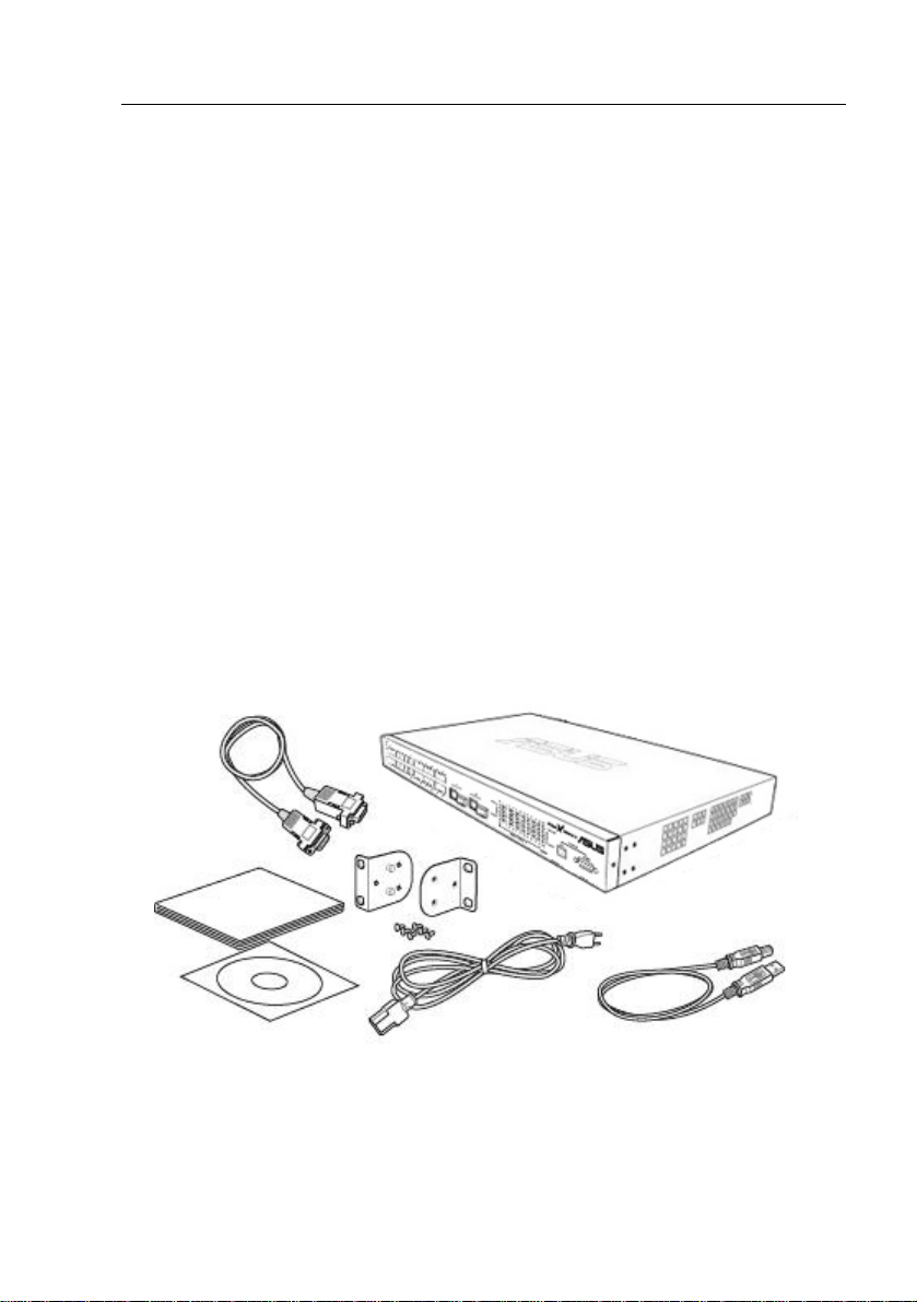
2.1 Package contents
The GigaX 2024X switch package comes with the following items:
• GigaX 2024X ( 26-port) L2 managed switch
• AC Power cord
• Null modem cable for console interface (DB9)
• Rack installation kit (two brackets with six #6-32 screws)
• USB cable for console interface
• Installation CD-ROM
• User Manual
• Quick installation guide
Figure 1. GigaX L2 managed switch package contents
13
Page 14
GigaX Series L2 Managed Switch User Guide
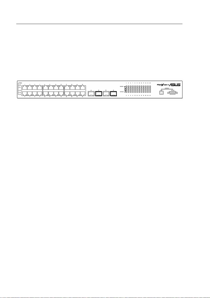
2.2 Front Panel
The front panel includes LED indicators that show the system, RPS, fan,
and port status.
Figure 2. Front panel
14
Page 15

GigaX Series L2 Managed Switch User Guide
Table 1. Front panel labels and LEDs
Label Color Status Description
SYSTEM
RPS
10/100/1000
port status
10/100/1000
port speed
Amber On Abnormal temperature or voltage
Off No power
Green On The PSU is working properly and the switch
Amber On The PSU is abnormal and the switch is
Off No power at all (system LED is also off), RPS
Green On Both fans are working properly FAN
Amber On Both or either one of the fans stopped
Green
off No Ethernet link
Amber
Green On 1000Mbps on Giga port, or 100Mbps on
Amber On 100Mbps on Giga port
Off 10Mbps or link is not present
On Unit is powered on Green
Flashing Self-test, INIT, or downloading
has a good redundant power supply
powered by RPS
does not work properly or not installed
(system LED is on)
On Link (RJ-45 or SFP) is present; port is
enabled
Flashing Data is being transmitted/received
On Link is present, but port is disabled either
manually or by spanning tree
Flashing Port is in one of the STP blocking, listening
and learning state
10/100 ports
15
Page 16
GigaX Series L2 Managed Switch User Guide
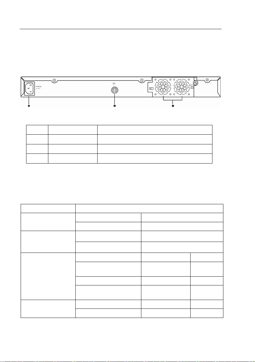
2.3 Rear Panel
The switch rear panel contains the ports for the data and power
connections.
Figure 3. Rear panel
No. Label Description
1 Power Connector Connects to the supplied power cord
2 RPS Redundant Power Supply connector
3 FAN1 – FAN2 Replaceable system fans
2.4 Technical specifications
Table 2. Technical specifications
Physical Dimensions 43.5mm(H) X 444 mm(W) X 265mm(D)
Input Consumption Power
100-240V AC/2.5A 50-60Hz < 90 watts
Supply (RPS)
Environmental Ranges
Input Output Redundant Power
100-240V AC/1.8A 50-60Hz 12V DC/12.5A
Operating Storage
Temperature -10 to 50 (14 to ℃
122 )℉
Humidity 15 to 90% 0 to 95%
Altitude up to 10,000 ft
(3,000m)
Dimensions Voltage and Current Speed: Replaceable Fans
40 x 40 x 20 mm 12VDC, 0.13A 8200RPM
16
-40 - 70℃
(-40 to 158 )℉
40,000 ft
(12,000m)
Page 17

GigaX Series L2 Managed Switch User Guide
3 Quick start guide
This section provides the basic instructions to set up the GigaX environment.
Refer also to the GigaX Series Installation Guide.
Part 1 shows you how to install the GigaX on a flat surface or on a rack.
Part 2 provides instructions to set up the hardware.
Part 3 shows you how to configure basic settings on the GigaX.
Obtain the following inf orma tion fro m your net work ad ministrat or bef ore
proceeding:
IP address for the switch
Default gateway for the network
Network mask for this network
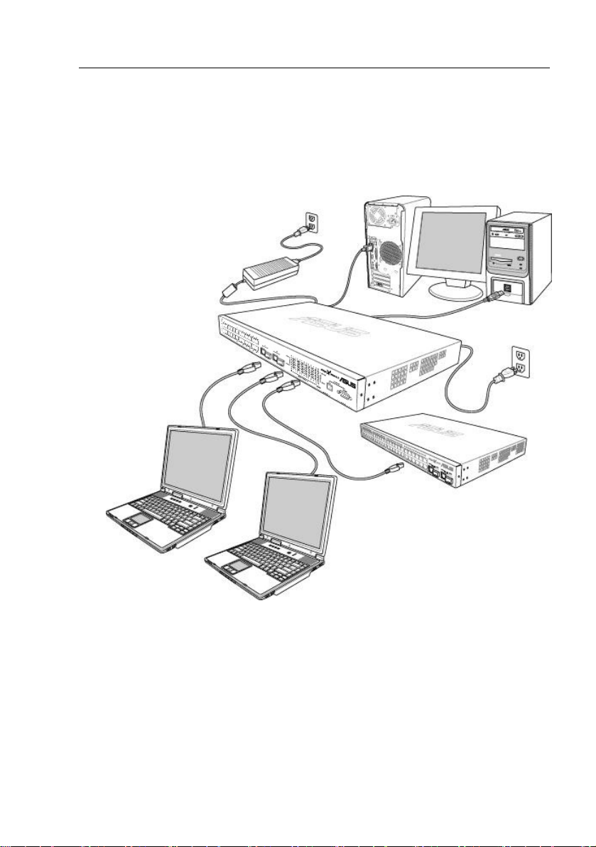
3.1 Part 1 — Installing the hardware
Connect the device to the power outlet, and your computer or network.
Figure 4 illustrates the hardware connections.
3.1.1 Installing the switch on a flat surface
The switch should be installed on a level surface that can support the weight of
the switches and their accessories. Attach four rubber pads on the marked
location on the bottom of the switch.
3.1.2 Mounting the switch on a rack
1. Attach brackets to each side of the switch and make the posts insert to
the switch.
2. Insert and tighten two screws to securely attach the bracket to the rack
on each side.
17
Page 18

GigaX Series L2 Managed Switch User’s Guide
3.2 Part 2 — Setting up the switch
Connect the device to the power outlet, and your computer or network. See
Figure 4.
3.2.1 Connect the console port
For console management, use an RS232 (DB9) or a USB cable to connect
the switch. If you want to use WEB interface, connect your PC to the switch
using the Ethernet cable.
3.2.2 Connect to the computers or a LAN
You can use Ethernet cable to connect computers dire ctly to the switch ports.
You can also connect hubs/switches to the switch ports by Ethernet cables.
You can use either the crossover or straight-through Ethernet cable to connect
computers, hubs, or switches.
Use a twisted-pair Category 5 Ethernet cable to connect the
1000BASE-T port. Otherwise, the link speed can not reach
1Gbps.
3.2.3 Attach the RPS module
Connect your RPS module to the RPS jack and make sure the other end of the
RPS is connected to the power cord. Connect to the power cord to a grounded
power outlet.
3.2.4 Attach the power adapter
1. Connect the AC power cord to the POWER receptacle on the back of
the switch and plug the other end of the power cord into a wall outlet or
a power strip.
2. Check the front LED indicators with the description in Table 4. If the
LEDs light up as described, the switch hardware is working properly.
18
Page 19
Cat 5 Ethernet cables
GigaX Series L2 Managed Switch User Guide
Console
RS-232
RPS
Management
USB
LAN computers
Figure 4. Overview of Hardware Connections
Expansion
hub/switch
19
Page 20

GigaX Series L2 Managed Switch User’s Guide
Table 3. LED Indicators
No. LED Description
1 System Solid green indicates that the device is turned
2 Switch ports
[1] to [26]
3 RPS Solid green indicates that the device has
4 Fan Solid green indicates that all fans work
on. If this light is off, check if the power
adapter if attached to the switch and plugged
into a power source.
Solid green indicates that the device can
communicate with the LAN, or flashing when
the device is sending or receiving data from
your LAN computer.
successfully installed an RPS module.
properly
3.3 Part 3 — Basic switch setting for
management
After completing the hardware connections, configure the basic settings for
your switch. You can manage the switch using the following methods:
• Web interface: the switch has a set of pages to allow to you manage it
using Java
®
-enabled IE5.0 or higher version.
• Command Line Interface: use console port to manage the switch.
3.3.1 Setting up through the console port
1. Use the supplied crossover RS-232 cable to connect to the console
port on the back of the switch. This port is a male DB-9 connector,
implemented as data terminal equipment (DTE) connection. Tighten
the retaining screws on the cable to secure it on the connector.
Connect the other end of the cable to a PC running terminal emulation
software. e.g. Hyper Terminal.
2. Use the supplied USB cable to connect to a PC. You have to install the
USB driver from the switch CD-ROM before the USB can work properly.
The USB drivers will simulate an additional COM port under Windo ws
ME/2K/XP OS.
20
Page 21
GigaX Series L2 Managed Switch User Guide
3. Make sure the settings of your terminal emulation software as follows:
a) Choose the appropriate serial port number
b) Set the data baud rate to 9600
c) Set the data format to no parity, 8 data bits and 1 stop bit
d) No flow control
e) Set VT1000 for emulation mode
4. After setting up the terminal, you can see the prompt “(ASUS)%” on the
terminal.
5. Type “login” to access the command line interface. The default user
name is “admin”. Skip the password by pressing <Enter>.
You can change the password at any time through CLI (see
section 5.3.1). To protect your switch from unauthorized
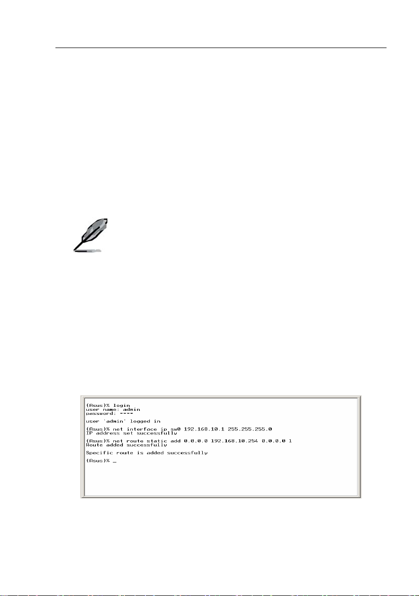
6. Follow these steps to assign an IP address to the switch:
a) Type “net interface ip sw0 <your ip address> <your network
mask>”. For example, if your switch IP is 192.168.10.1 and the
network mask is 255.255.255.0. Then you should type “net
interface ip sw0 192.168.10.1 255.255.255.0”.
access, you must change the default password as soon as
possible.
b) If the switch has to be managed across networks, then a default
gateway or a static route entry is required. Type “net route static
add 0.0.0.0 <your network gateway IP> 0.0.0.0 1” as your default
route entry, as shown in
Figure 5.
Figure 5. Login and IP setup Screen
21
Page 22
GigaX Series L2 Managed Switch User’s Guide
3.3.2 Setting up through the Web interface
To successfully connect your PC to the switch, your PC must a valid IP in your
network. Contact your network admini strator t o obtai n a valid IP f or the switch.
If you wish to change the default IP address of the swit ch, follow secti on 3.3.1
to change the IP address. Since the switch supports DHCP client function, a
valid static IP for the switch can be configured or get a dynamic IP by DHCP
client through Web interface.
1. It is not necessary to login Web interface at the first time to use Web
interface because the default configuration for Web access
authentication is disabled. To secure the system configuration, please
enable the authentication function at the “Administration” page under
“System” category. Skip step 2 if the authentication is disabled.
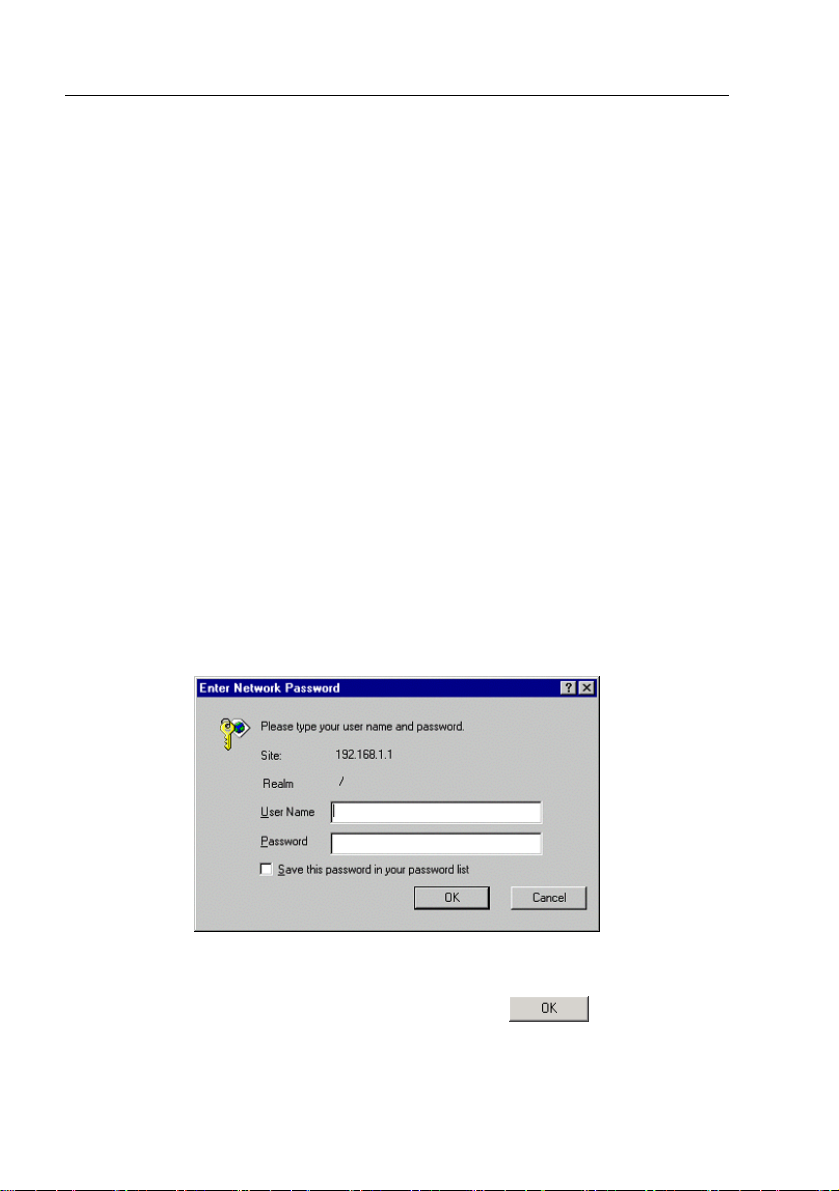
2. At any PC connected to the network that the switch can access , open
your Web browser (Internet Explorer), and type the following URL in the
address/location box, and press <Enter>:
http://192.168.1.1
This is the factory defa ult IP address of the switch.
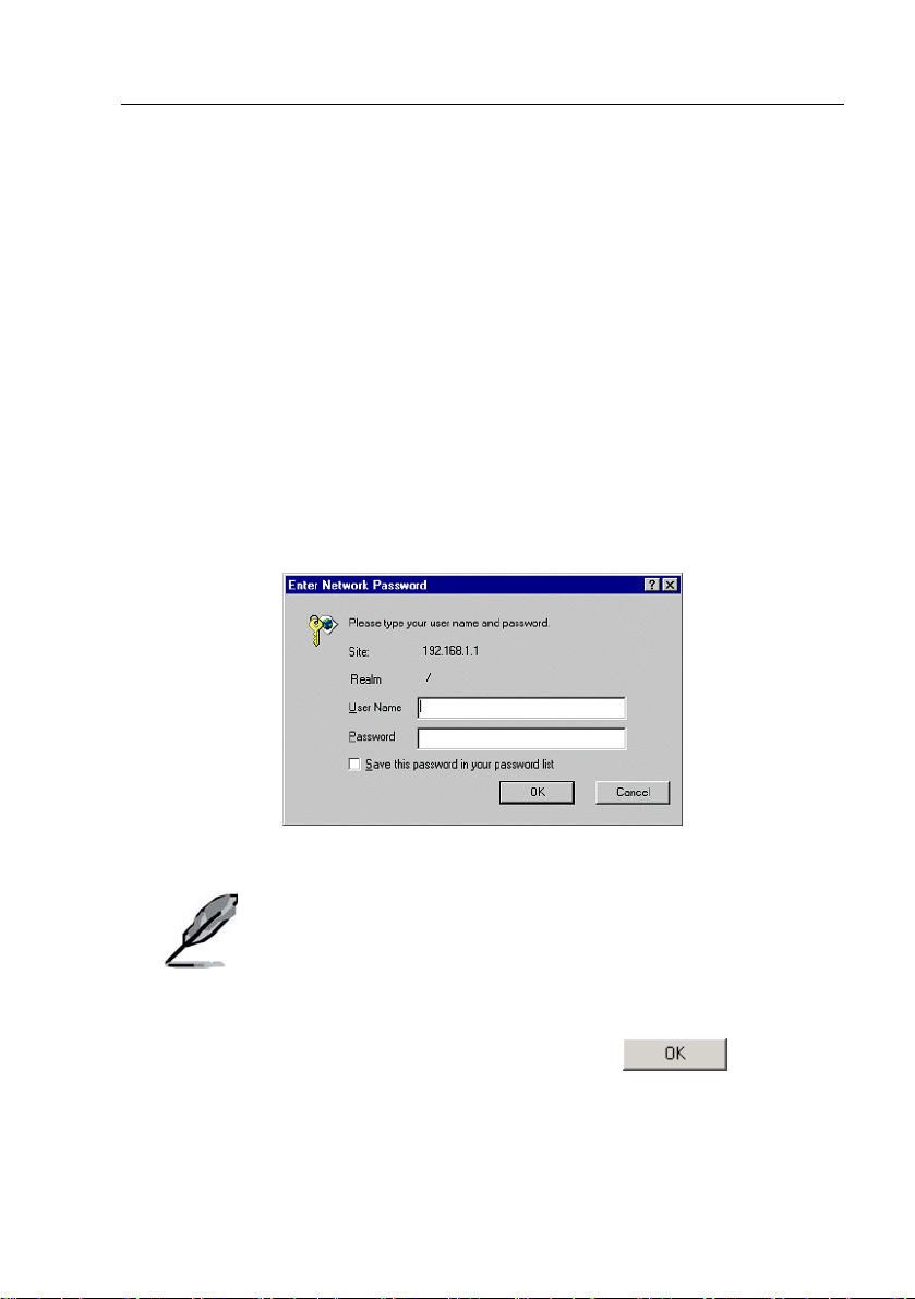
A login screen appears, as shown in
Figure 6. Login Screen
Enter your user name and password, a nd then click to enter the
Configuration Manager. Use the following defaults the first time you log into
this interface:
22
Figure 6.
Page 23
GigaX Series L2 Managed Switch User Guide
Default User Name: admin
Default Password: (no password)
You can change the password at any time (see section
5.3.1 System Commands).
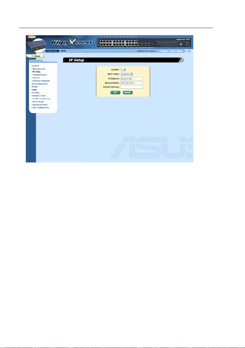
3. To setup a new IP address, click “System”, then “IP Setup” (see Figure
8). Fill in the IP address, network mask and default gateway, then click
.
4. If your new address is different from the default, the browser can not
update the switch status window or retrieve any page. This is normal.
You have to retype the new IP address in the address/location box, and
press <Enter>. The WEB link returns.
5. To enable authentication for Web access, click “Administration” on
the menu list, then select “Enabled” to start the protection.
A login window appears i mmedi ately afte r you click
figures on the next page.
. See the
23
Page 24
GigaX Series L2 Managed Switch User’s Guide
Figure 7. IP Setup
24
Page 25
GigaX Series L2 Managed Switch User Guide
4 Management with the Web Interface
The switch provides Web pages that allow swit ch man agement th rough the
Internet. The program is designed to work best with Microsoft Internet
Explorer® 5.5, or later versions. NOTE: Netscape is not supported.
4.1 Log into Web user interface
1. From a PC, open your web browser, type the following in the web
address (or location) box, and press <Enter>:
http://192.168.1.1
This is the factory default IP address f or th e switch. A l ogin screen
displays, as shown in
Figure 8.
Figure 8. Configuration manager login screen
2. Enter your user name and password, then click .
Login is not required if you do not enable Web aut hentication
access (see 3.3.2)"
25
Page 26
GigaX Series L2 Managed Switch User’s Guide
Use the following defaults the first time yo u log int o the prog ram. You ca n
change the password at any time through CLI i nterface (see section
5.3.1 )
Default User Name:
Default Password:
admin
<no password>
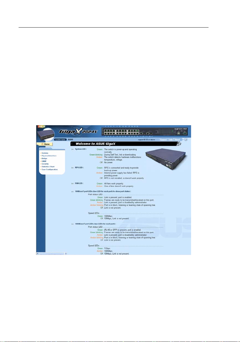
The home page appears each time you log into the program.(See Figures 9).
26
Figure 9. Home page
Page 27
GigaX Series L2 Managed Switch User Guide
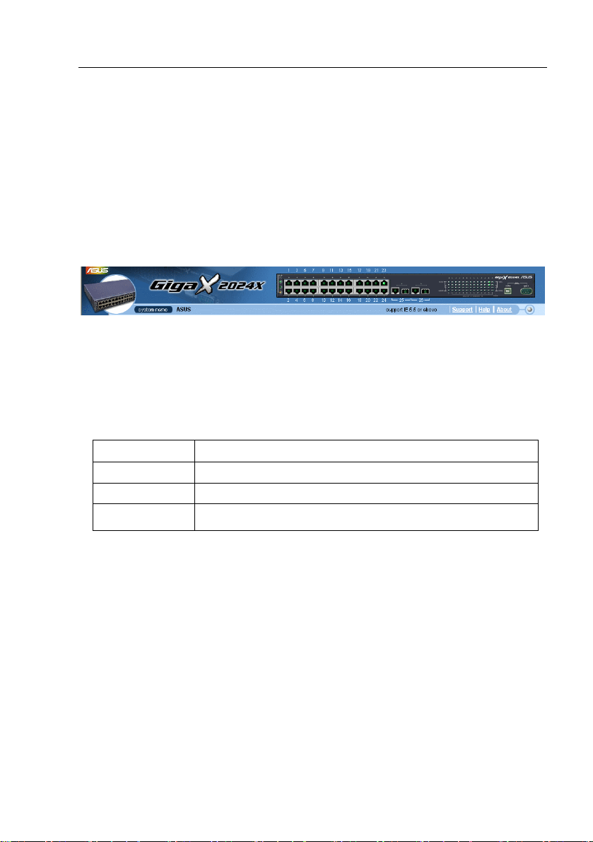
4.2 Functional layout
Typical web page consists of three separate frames. The top frame has a
switch logo and front panel as shown in Figures 10. This frame remains on the
top of the browser window all the times and updates the LED status
periodically. See Table 4 for the LED definition s. See Table 5 for the col or
status description.
Figure 10. Top frame
Table 4. Port color description
Port Color Description
Green port Ethernet link is established
Black No Ethernet link
Amber port Link is present but port is disabled manuall y or by spanning tree
Clicking on the port icon of t he switch display s the p ort conf iguratio n in the
lower right frame.
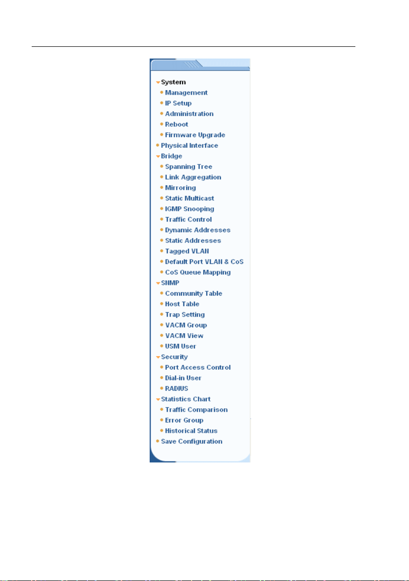
The left frame, a menu fram e as shown in
Figure 11, contains all the features
available for switch configurati on. These featu res are grouped int o categori es,
e.g. System, Bridge, etc. You can click on any of these to display a spe cific
configuration page.
27
Page 28
GigaX Series L2 Managed Switch User’s Guide
Figure 11. Expanded Menu List
The right frame displays configuration pages or graphics for the statistics.
See section
28
4.3 for details.
Page 29
GigaX Series L2 Managed Switch User Guide
4.2.1 Menu navigation tips
• To expand a group of related menus, c lick on the corresponding group
name. The
sign will change to after expansion.
• To contract a group of related menus: click on the corresponding group
name. The
sign will appear next to the group name.
• To open a specific configurat ion page, click on th e desire d menu ite m.
•
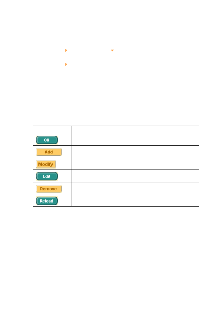
4.2.2 Commonly used buttons and icons
The following table describes the f unction for each butto n and icon u sed in the
application.
Table 5. Commonly used buttons and icons
Button/Icon Function
Stores any changes you have made on the current page.
Adds the existing configuration to the system, e.g. a static MAC
address or a firewall ACL rule and etc.
Modifies an existing entry
Modifies the existing configuration in the system, e.g. a static route
or a filter ACL rule and etc.
Deletes the selected item, e.g. a static route or a filter ACL rule and
etc.
Re-displays the current page with updated statistics or settings.
29
Page 30
GigaX Series L2 Managed Switch User’s Guide
4.3 System Pages
System pages include management, IP setup, administration, reboot, and
firmware update function.
4.3.1 Management
The Management page contain s the foll owing i nformation:
Model Name: product name
MAC Address: switch MAC address
System Name: user assigned name to identify the system (editable)
System Contact (editable)
System Location (editable)
To save any changes and make it effective immediately, cli ck
to refresh the setting, as shown in Figure 12.
30
. Use
Page 31

GigaX Series L2 Managed Switch User Guide
Figure 12. Management
31
Page 32

GigaX Series L2 Managed Switch User’s Guide
4.3.2 IP Setup
The switch supports dynamic IP and static IP assignment. The dynamic IP is
get from a DHCP server within the same VLAN. The IP Setup page contains
the following editable informati on:
VLAN ID: Specify a VLAN ID to system management interface. It is
necessary to be within the same VLAN for management usages.
DHCP Client: Enable DHCP to get a dynamic IP address, or disable
DHCP to specify a static IP address. The DHCP server must be reachable
within the management VLAN.
IP Address: assign a static IP address to the switch management
interface.
Network Mask
Default Gateway
To save any changes and make it effective immediately, click
to refresh the setting, as shown in Figure 13.
32
. Use
Page 33

GigaX Series L2 Managed Switch User Guide
Figure 13. IP Setup
33
Page 34

GigaX Series L2 Managed Switch User’s Guide
4.3.3 Administration
The Administration pa ge allows you ena ble or disable the a uthenticatio n for
web user by password protection. The default setting for web access does not
require any authentication.
To save any changes and make it effective immediately, click
to refresh the setting, as shown in Figure 14. When you enable the
password protection, you have to login again imm ediately.
You can change the password at any time through the CLI
interface.
. Use
34
Figure 14. Administration
Page 35

GigaX Series L2 Managed Switch User Guide
4.3.4 Reboot
The Reboot page contains a button. Clicking the button reboots the
system.
Rebooting the system stops the network traffic and
terminates the Web interface connection.
Figure 15. Reboot
4.3.5 Firmware Upgrade
The Firmware page contains the following information:
Hardware Version: shows the hardware revision number.
Boot ROM Version: shows the v ersion of t he boot code
Firmware Version: shows the current running firmware version. This
number will be updated after the firmware update.
35
Page 36

GigaX Series L2 Managed Switch User’s Guide
Enter the firmware location into the firmware space directly, or cl ick
to choose the file name of the firmware from prompt window. Click
to update the switch firmware. See Figure 16 for ref erence.
Clicking the upload button loads the assigned firmware to the
switch, then reboot system after a successful firmware
update. You have to re-login to Web interface again
36
Figure 16. Firmware Upgrade
Page 37

GigaX Series L2 Managed Switch User Guide
4.4 Physical Interface
The Physical Interface displays the Ethernet port status in real time. You can
configure the port in followin g field s:
Port: select the port to configure
Admin: disable/enable the port
Mode: set the speed and duplex mode
Flow Control: enable/disable 802.3x flow control mechanism
Port Status Window: displays the fol lowing inf ormation f or each p ort
a) Link status: the link speed and duplex for an existing link,
otherwise link is down
b) State: the STP state
c) Admin: the setting value to disable or enable the port
d) Mode: the setting value for link speed and duplex mode
e) Flow Control: the setting value to enable or disable 802.3x flow
control mechanism
Select the corresponding port number and configure the port setting, then click
on the
display window. However, the new settings do not take effect until the “Save
Configuration” is execut ed.
button. The field you change will update the content of the
37
Page 38

GigaX Series L2 Managed Switch User’s Guide
Figure 17. Physical Interface
38
Page 39

GigaX Series L2 Managed Switch User Guide
4.5 Bridge
The Bridge page group contains most layer 2 configurations, like link
aggregation, STP etc..
4.5.1 Spanning Tree
The configuration page for Spanni ng Tree Protocol can disabl e and enable the
feature in runtime. This page cons ists of th ree part s.
The first part shows the root inform ation. It tells user the STP setting about the
root switch.
The second part is the STP setting. The following options are avail able:
Disable/STP Enable/RSTP Enabled: Turn the STP/RSTP off/on. When
you turn the STP/RSTP on, STP/RSTP will use the following settings if the
switch is the root switch.
Hello Time: the interval between t he gen eration of co nfiguratio n BPDU
Max Age: a timeout value to be used by all Bridges in the LAN
Forward Delay: a timeout value to be used by all bridge s in the LAN
Bridge Priority: the switch priority in the LAN
The third part is the port sett ing. It conta ins a disp lay window t o show the
current configuration for each p ort. You cli ck
setting for STP/RSTP. The following fields are available:
Port: select the corresponding port to configure
Priority: the port priority in the switch. Low numeric va lue indi cates a hi gh
priority. The port with lower priority is more likely to be blocked by STP if a
network loop is detected. The va lid value i s from 0 to 240.
Cost: the valid value is from 1 to 2000000 00. The higher co st is more
likely to be blocked by STP if a network loop is detected.
FastLink: make the port in forwarding state when a link comes up, then
the port will participate STP resolutions.
to change the port
39
Page 40

GigaX Series L2 Managed Switch User’s Guide
Edge Port: All ports are set to be edge ports by default. Edge port
becomes STP port when BPDU is received. Also, it takes very short time
for an edge port to be in forwarding state.
Point to Point: Auto/Yes/No. A full duplex link is considered as a point to
point link. Otherwise, it is a shared link. Point to point link may have less
convergence time. Auto is recommended in most cases.
Click
settings to current value.
to make the settings effective. Click to refresh the
Figure 18. Spanning Tree
4.5.2 Link Aggregation
The page configures the link aggregation group (port trunking). The switch
can have 15 link aggregation groups.
Show Trunk: Select “Add a new Trunk” for a new create d group. Or select
an existed group to display on t he foll owing fiel ds and p ort icons.
40
Page 41

GigaX Series L2 Managed Switch User Guide
Name: the group name.
Trunk ID: a number to identify the trunk group besides the group name.
LACP: Enable/Disable LCAP on selected trunk. LACP mode is fixed to be
Active.
Remove Trunk: Remove the selected trunk.
Port Icons: these port icons are listed in a way like the front panel. You
have to click on the icon the select the group members. Th e port can be
removed from the group by clicking th e selected p ort again.
Click
to make the setting send to the switch (HTTP serv er). Cli ck
to refresh the settings to current value. To make the configurati on
effective, go to “Save Configuration” page, then click
.
You have to check the runtime l ink spee d and du plex mod e to make sure the
trunk is physically active. Go to Physical Interface and check the link mode in
the runtime status window for t he trunk ports. If all the trunk members are in the
same speed and full duplex mode, then the trunk group i s set up successfully.
If one of the members is not in the same speed or full duplex mod e, the trunk is
not set correctly. Check the link partner and change the setti ngs to have the
same speed and full duplex mode for all the mem bers of your trunk g roup.
•
• All the ports in the link aggregation group MUST operate
in full-duplex mode at the same speed.
• All the ports in the link aggregation group MUST be
configured in auto-negotiation mode or full duplex mode.
This configuration will make the full duplex link possible. If
you set the ports in full duplex force mode, then the link
partner MUST have the same setting. Otherwise the link
aggregation could operate abnormally.
• All the ports in the link aggre gation group MUST have the
same VLAN setting.
• All the ports in the link aggregation group are treated as a
single logical link. That is, if any member changes an
attribute, the others will change too. For example, a trunk
41
Page 42

GigaX Series L2 Managed Switch User’s Guide
group consists of port 1 and 2. If the VLAN of port 1
changes, the VLAN of port 2 also changes with port 1.
Figure 19. Link aggregation
4.5.3 Mirroring
Mirroring, together with a network traffic analyzer, helps you monitor
network traffics. You can monitor the selected ports for egress or ingress
packets.
Mirror Mode: Enables or disables the mirror function for the selected
group.
42
Page 43

GigaX Series L2 Managed Switch User Guide
Monitor Port: Receives the copies of all t he traff ics in the select ed
mirrored ports.
The monitor port can not belong to any link aggregation group.
The monitor port can not operate as a normal switch port. It does
not switch packets or do address learning.
Click to make the setting send to the sw itch (HT TP server). C lick
to refresh the settings to cu rrent value.
Figure 20. Mirroring page
43
Page 44

GigaX Series L2 Managed Switch User’s Guide
Static Multicast
This page can add multicast addresses into the multicast table. The switch can
hold up to 256 multicast entries. All the ports in the group will forward the
specified multicast packets to other ports in the group.
Show Group: selects “Add a new Group” to enter a new entry. Or select
an existing group address to display
MAC Address: selects the multicast address
VLAN: selects the vlan group
Click
settings to current value.
to make the setting effective. Click to refresh the
Figure 21. Static Multicast
44
Page 45

GigaX Series L2 Managed Switch User Guide
4.5.4 IGMP Snooping
IGMP snooping helps to reduce the multicast traffics on the network by
allowing the IGMP snooping function to be turned on or off. When turned on,
the switch snoops the IGMP packets and puts the new group into the multicast
table. However, if the static entries occupy all 256 spaces, the IGMP snoop
does not work normally. The switch only allows 256-layer 2 multicast group.
Figure 22. IGMP Snooping
4.5.5 Traffic Control
Traffic control prevents the switch bandwidth from flooding packets including
broadcast packets, multicast packets. The limit number is a threshold to limit
the total number of the checked type pa ckets. For ex ample, if broadcast /
multicast is enabled, the traffic amount of each type will not exceed the limit
value. Click
configuration effective, go to “Save Configuratio n” page, then click
to save the new configuratio n. To make th e
45
.
Page 46

GigaX Series L2 Managed Switch User’s Guide
Figure 23. Traffic Control
4.5.6 Dynamic Addresses
This page displays the result of dynamic MAC address lookup by port, VLAN
ID, or specified MAC address. The dynamic address is the MAC address
learned by switch, it will age out f rom the a ddress ta ble if the addre ss is not
learned again during the age time. User can set the age time by ent ering a
valid number from 15 to 3825 in seconds. Then click on
new age value. To make the co nfiguratio n effectiv e, ple ase go to “Save
Configuration” page, then click on
You can look up MAC addresses by checking the port, VLA N ID, or/and MAC
address, then click on
of the query.
46
. The address window will display the result
.
to save the
Page 47

GigaX Series L2 Managed Switch User Guide
Figure 24. Dynamic Address
47
Page 48

GigaX Series L2 Managed Switch User’s Guide
4.5.7 Static Addresses
You can add a MAC address i nto the swi tch addre ss tabl e. The MA C addres s
added by this way will not age out from the address table. We call it static
address.
MAC Address: enter the MAC address
VLAN ID: enter the VLAN ID that the MAC belongs
Port Selection: select the port which the MAC belongs
Click on
information. Then you will see the new added entry shows in the address
window. In one page, 15 entries can be displayed in the address window.
When you create more than 15 entries, the new added entrie s will display in
the next page. You can click on F irst, Previous, Next, or Last t o go through the
pages of static MAC address, or input the page number and then click on Go.
You can remove the existed address by selecting the ent ry with the mouse,
then clicking on
address entries. You can look up a stati c MAC addresses by inp ut the MAC
address and VLAN ID, then click on
the result of the query. Click
the settings to current value. To make t he config uration effective, please g o to
“save configuration” page, then click
when you create a new stati c MAC ad dre ss by the a bove
. The button updates t he exist ed MAC
. The address window will mark
to save effective. Click to refresh
.
48
Page 49

GigaX Series L2 Managed Switch User Guide
Figure 25. Static Address
4.5.8 Tagged VLAN
You can set up to 256 VLAN groups and show VLAN group in this page. There
is a default VLAN created by the switch. It cannot be removed at all. This
feature prevents the switch from malfunctions. You ca n remove any exist ed
VLAN except the default VLAN.
You can assign the port to be a tagged port or an untagged port by toggling the
port button. There are three type s of butt on disp lays:
“U” type: untagged port that will remove VLAN tags from the transmitted
packets.
“T” type: All packets transmitted from this port will be tagged.
“Blank” type: This port is not a member of the VLAN group.
49
Page 50

GigaX Series L2 Managed Switch User’s Guide
If one untagged port belongs to two or more VLAN groups at the same time, it
will confuse the switch and cause flooding traffics. To prevent it, the switch only
allows one untagged port b elongs to o ne VLA N at the sa me time. T hat is, th e
untagged port belongs to the VLAN group which is called “PVID” and
configured in the “Default Port VLAN & CoS” page. If you want to assign an
untagged port from one VLAN t o another, you have to remove it f rom the
original VLAN, or change it to be tagged in the original VLAN first.
Show VLAN: select the existed VLAN to display or select “Add a new
VLAN” to create a new VLAN gro up
Name: the VLAN name
VLAN ID: this field requires user to enter the VLAN ID when a new VLAN
is created
Remove VLAN: Remove a existed VLAN. This field disappears in VLAN
creation page.
Click on
effective, go to “Save Configuration” page, then click on
50
to save the configuration. To make the configuration
.
Page 51

GigaX Series L2 Managed Switch User Guide
Figure 26. Tagged VLAN
51
Page 52

GigaX Series L2 Managed Switch User’s Guide
4.5.9 Default Port VLAN and CoS
Some VLAN tag related field settings for each port are in cluded in this page. It
includes:
Port: select the port to configure
PVID: port-based VLAN ID. Every untagged packet received from this
port will be tagged with this VLAN group ID
CoS (Class of Service) value: ev ery untag ged packet received f rom th is
port will be assigned to this CoS in the VLAN tagged.
Click on
to save the configuration. To make the configur ation effectiv e, go to
“Save Configuration” page, then click
to change the content in the port list window. Click on
Figure 27. Default Port VLAN and CoS
.
52
Page 53

GigaX Series L2 Managed Switch User Guide
4.5.10 CoS Queue Mapping
The switch supports 4 egress queues for each port. For each queue, you
can specify the scheduling types as follows:
• Strict priority scheduling: each CoS value can map into one of the four
queues. The queue 4 has the hi ghe st priority to t ransm it the p acket s. And
packets in the low-priority queue do not transmit until all the high-priority
queues become empty. In Strict priority scheduling, weight settings always
zero.
• Weighted round-robin (WRR) scheduling: WRR scheduling requires you
to specify a number the indicates the impo rtance (weight) of the queue
relative to other CoS queues. WRR schedulin g prevents the low-priority
queues from being completely neglected during periods of high-priority
traffic. The WRR scheduling transmits some packets from each queue in
turn. The number of packets it sends corresponds to the relative
importance of the queue. For example, if Que ue1 has a weight of 1 and
Queue2 has a weight of 2, one packet is sent from the Queue1 for every
two that are sent from the Queue2. By using this scheduling, low-priority
queues have the opportunity to send packets even through the
high-priority queues are not empty. The fixed weights are 1,2,4,8.
Click to save the configuration. Click on to refresh the
settings to current value. To make the configuration effe ctive, go to “Save
Configuration” page, then click
53
Page 54

GigaX Series L2 Managed Switch User’s Guide
Figure 28. Cos Queue Mapping
54
Page 55

GigaX Series L2 Managed Switch User Guide
4.6 SNMP
This group offers the SNMP conf iguratio n inclu ding Co mmunity Table, Ho st
Table, and Trap Se tting. To prov ide more secure m anagem ent and
access control, SNMPv3 is supported.
4.6.1 Community Table
You can type different community names and specify whether th e community
has the privilege to make a setting (write acce ss) by checking th e box. Click
to save the configuration permanently or to refresh the
page.
Figure 29. Community Table
55
Page 56

GigaX Series L2 Managed Switch User’s Guide
4.6.2 Host Table
This page links host IP address to the community name that is entered in
Community Table page. Type an IP address and select the communi ty name
from the drop-down list. Click
permanently or
to refresh the page.
to save the configuration
56
Figure 30. Host Table
Page 57

GigaX Series L2 Managed Switch User Guide
4.6.3 Trap Setting
By setting trap destination IP add resses and community names, y ou can
enable SNMP trap function to send trap packets in different versions(v1 or v2c).
Click
refresh the page.
to save the configuration perma nently or to
Figure 31. Trap Setting
4.6.4 VACM Group
VACM(View-based Access Control Model) Group is used to configure the
information of SNMPV3 VACM Group.
Group Name: enter the security group name.
Read View Name: enter the Read View Name that the Group belongs.
The related SNMP messages are Get,GetNext,GetBulk.
57
Page 58

GigaX Series L2 Managed Switch User’s Guide
Write View Name: enter the Write View Name that the Group belong s.
The related SNMP message is Set.
Notify View Name: enter the Notify View Name that the Group belongs.
The related SNMP messages are Trap,Report..
Security Model: enter the Security Model Name that the Group belongs.
Any is suitable for v1,v2,v3. USM is SNMPv3 related.
Security level: enter the Security level Name that the Group belong s. Only
NoAuth, AuthNopriv, AuthPriv can be chosen.
Click on the
above information. Then you will see the new added entry shows in the group
window. You can remove the existed group by selectin g the entry with the
mouse, then clicking on
VACM Group entries. Click
refresh the settings to current value. T o make the conf iguration effective,
please go to "Save Configuration" page, then click on
when you create a new VACM grou p entry by th e
. The button updates the existed
to save effectively. Click to
.
58
Page 59

GigaX Series L2 Managed Switch User Guide
Figure 32. VACM Group
4.6.5 VACM View
VACM (View-based Access Control Model) View is used to view the
information of SNMPV3 VACM Group.
View Name: enter the security group name.
View Type: select the View Type that the View belongs. Included or
Excluded when View Subtree matches the Oid in the SNMPv3 message.
View Subtree: enter the View Subt ree that the View belongs. The Subtre e
is the Oid to match the Oid in the S NMPv3 me ssage. The match i s good
when the subtree is shorter tha n the Oi d in the S NMPv3 me ssage.
View Mask: enter the View Mask that the View belongs. Each bit in the
mask represents the digit b etween the dots of V iew Subtree from left side.
Bit ‘0’ means ‘don’t care’.
59
Page 60

GigaX Series L2 Managed Switch User’s Guide
Click on the
information. Then you will see the new added entry shows in the view window.
You can remove the existed views by selecting the entry with the mouse, then
clicking on
entries. Click
settings to current value. To make the configuration effe ctive, please go to
"Save Configuration" page, then click on
when you create a new VACM View entry by th e above
. The button updates the existed VACM View
to save effectively. Click to ref resh the
.
Figure 33. VACM View
4.6.6 USM User
USM (User-based Security Mo del) User is u sed to confi gure the inf ormation of
SNMPV3 USM User.
Engine Id: enter the Engine Id that matches the ID in the Manager..
60
Page 61

GigaX Series L2 Managed Switch User Guide
Name: enter Name combined with Engine ID that should mat ch the Name
and Engine ID in the Manager.
Auth Protocol: enter the Auth P rotocol t hat Engin e ID and Name bel ong.
Only NoAuth ,MD5, SHA1 can be chosen. If the NoAuth is chosen, there
is no need to enter password.
Auth Password: enter the password that the Auth Protocol belongs. The
password needs at least 8 characters or digits.
Priv Protocol: enter the Priv Protocol that Engine ID and Name belong.
Only NoPriv ,DES can be chosen. If the NoPriv is chosen, there is no
need to enter password.
Priv Password: enter the password that the Priv Protocol belongs. The
password needs at least 8 characters or digits.
Click on the
information. Then you will see the new added entry shows in the User window.
You can remove the existed User by selecting the entry with the mouse, then
clicking on
entries. Click
settings to current value. To make the configuration effe ctive, please go to
"Save Configuration" page, then click on
when you create a new USM User entry by the above
. The button updates the existed USM User
to save effective. Clic k to refresh the
.
61
Page 62

GigaX Series L2 Managed Switch User’s Guide
Figure 34. USM User
62
Page 63

GigaX Series L2 Managed Switch User Guide
4.7 Security
The switch has the 802.1x port-based security feature. Only authorized hosts
are allowed to access the swit ch port. Traffic is b locked fo r hosts f ailed to
authenticate themselves. The auth enticatio n service is provi ded by a RADIUS
server or the local database in the switch.
The switch also supports dynamic VAL N assignment t hrough 802. 1x
authentication process. The VLAN information for the users/ports should be
configured in the authentication server properly before enabling this feature
4.7.1 Port Access Control
Port Access Control is used to configure various 802.1x parameters.
802.1x uses either RADIUS server or local database to authenticate port
users.
The first part is the Bridge (Global) settings:
• Reauthentication: Once enabled, the switch will try to authenticate the port
user again when the re-authent icatio n time is up.
• Reauthentication Time: If 'Reauthentication' is enabled, this is the interval
for the switch to re-send authentication request to the port user.(see
above)
• Authentication Method: RADIUS or Local database can be used to
authenticate the port user.
• Quiet Period: If authentication failed either from RADIUS or local database,
the switch waits upon this time period before sending another
authentication request to the port user.
• Retransmission Time: If the port user failed to respon d to authentication
request from the switch, the switch waits upon this time period before
sending another authentication request to the port user.
• Max Reauthentication Attempts: Retry count if the port user failed to
respond to authentication requests from the switch.
.
The second part is the port settings. Please click
finished the modifications.
• Port: Specify which port to be configured.
when you have
63
Page 64

GigaX Series L2 Managed Switch User’s Guide
• Multi-host: If enabled, all hosts connected to the selected port are allowed
to use the port if one of the hosts passed the authentication. If disabled,
only one host among other hosts passed the authentication is allowed to
use the port.
• Authentication Control: If 'force authorized' is selected, the selected port is
forced to be authorized. Thus, traffic from all hosts is allowed to pass.
Otherwise, if 'force unauthorized' is selected, the selected port is blocked
and no traffic can go through. If 'Auto' is selected, the behavior of the
selected port is controlled by 802.1x protocol. All ports should be set to
'Auto' under normal conditions.
• Guest VLAN: Specify a guest VLAN to clients that are not 802.1x-capable.
Click
to refresh the settings to current value.
to make the settings effective permanently. Click
Figure 35. ort Access Control
P
64
Page 65

GigaX Series L2 Managed Switch User Guide
4.7.2 Dial-In User
Dial-in User is used to define users in the local database of the switch.
• User Name: New user name.
• Password: Password for the new us er.
• Confirm Password: Enter the password again.
• Dynamic VLAN: Specify the VLAN ID assigned to the
802.1x-authenticated clients.
Please click
finished the modifications. Click
selected user. Click
Click
to refresh the settings to current value.
to add the new user. Click when you have
Figure 36. ial-In user
when you want to remove the
to make the settings effective permanently.
D
65
Page 66

GigaX Series L2 Managed Switch User’s Guide
4.7.3 RADIUS
In order to use external RADIUS server, the following parameters are
required to be setup:
• Authentication Server IP: The IP address of the RADIUS server.
• Authentication Server Port: The port number for the RADIUS server is
listening to.
• Authentication Ser ver Key: The key is used for commun ications between
GigaX and the RADIUS s erver .
• Confirm Authentication Key: Re-type the key e ntered above.
•
The VLAN of the RADIUS server connected to the switch must be
the same as the VLAN of the system management interface.
•
Please click
to make the settings permanent. Click to
refresh the settings to current value.
Figure 37. RADIUS
66
Page 67

GigaX Series L2 Managed Switch User Guide
4.8 Statistics Chart
The Statistics Chart pages provide network flow in different charts. You can
specify the period time to refresh the chart. You can monitor the network traffic
amount in different graphic chart by these pages. Most MIB-II counters are
displayed in these charts.
Click Refresh Rate to set the period for retrieving new data from the swit ch.
You can differentiate the statisti cs or ports by sele cting Color. Finally, click on
Draw to let the browser to draw the graphic chart. Each new Draw will reset
the statistics display.
4.8.1 Traffic Comparison
This page shows the one statistics item for all the ports in one graphic chart.
Specify the statistics item to di splay and click th e Draw, the browser will show
you the update data and ref resh t he grap hic pe riodi cally.
67
Page 68

GigaX Series L2 Managed Switch User’s Guide
Figure 38. Traffic comparison
4.8.2 Error Group
Select the Port and display Color, then click the Dra w, the statistics window
shows you all the discards or error counts for the speci fied port. The d ata is
updated periodically.
68
Page 69

GigaX Series L2 Managed Switch User Guide
Figure 39. Error group
4.8.3 Historical Status
You can display information for d ifferent port s and stat istics ite ms in t his chart .
Since this shows the history of the statistics inform ation, the chart can keep the
old data even it is refreshed.
69
Page 70

GigaX Series L2 Managed Switch User’s Guide
70
Figure 40. Historical Status
Page 71

GigaX Series L2 Managed Switch User Guide
4.9 Save Configuration
To save configuration permanently, you shoul d click . The setting
also takes effective after a successful save.
Sometimes you may want to re set the swit ch confi guration, y ou ca n cli ck on
to reset the configuration file to factory default. Of course, a syst em
reboot will follow this restoration process.
You will lose all the configurations when you choose to
restore the factory default configurations.
Figure 41. Save Configuration
71
Page 72

GigaX Series L2 Managed Switch User’s Guide
5 Console Interface
This chapter describes how to use console interface to configure the switch.
The switch provides RS232 and USB connectors to connect your PC. Use a
terminal emulator on your PC such as HyperTe rminal and com mand line
interpreter to configure the swit ch. You h ave to set up the termi nal emul ator
with baud rate 9600, 8 bit data, no parity, and 1 stop bit, and no flow control.
Once you enter CLI mode, type “?” will display all available command help
messages. This is very useful when you are not familiar with the CLI
commands. The CLI mode times out when idle for 10 minutes. You have to
login again to enter CLI mod e after t he timeo ut.
All the CLI commands are case sensitive. In order to make them easier to use,
you can enter into different category by typin g the full co mmand, then t his
category becomes your working category. Thereafter, you don’t have to type
“sys” before any sub-commands. For example, “sys” is a command category
including a lot of sub-commands. You don’t have to type “sys” for the
sub-commands once you change your working category to “sys” by typing
“sys”. The prompt will become “(system name) sys%” when your working
category is “sys”.
72
Page 73

GigaX Series L2 Managed Switch User Guide
5.1 Power On Self Test
POST is executing during the system booting time. It tests sy stem memo ry,
LED and hardware chips on the switchboard. It displays system information as
the result of system test and initi alizatio n. You can igno re the informa tion until
the prompt, “(ASUS) %”, appears (see Figure 43).
Figure 42. CLI interface
73
Page 74

GigaX Series L2 Managed Switch User’s Guide
5.1.1 Boot ROM Command Mode
During the POST process, you can enter a “Boot ROM Command” mode by
pressing <ENTER> key as shown in Figure 43.
Figure 43 shows dual images in the switch.
Enter the “?” key to show the help messages for all available commands.
Although the commands are helpful in some situation, we
STRONGLY suggest users not to use them if you don’t
know the command function.
74
Figure 43. Boot ROM Command Mode
Page 75

GigaX Series L2 Managed Switch User Guide
5.1.2 Boot ROM Commands
Type “?” in the boot mode to display the valid commands list.
Table 6. Boot ROM commands
Command Parameters Usage Notes
c IP address Configure TFTP client IP
address
g NONE Load and execute firmware
h NONE Display online help
m mask Configure network mask
p NONE Display current
configuration
r NONE System reboot
s IP address Configure TFTP server IP
address
t NONE Toggle safe mode
u File name Upload boot
module/firmware via
network using TFTP
protocol
v NONE Display boot rom version
w NONE Toggle administrator
password reset
75
Page 76

GigaX Series L2 Managed Switch User’s Guide
5.2 Login and Logout
By typing “login” to enter the CLI mode, you have to give a valid user name
and password. As the first time login, you can enter “admin” as the user name
and bypass the password. For security reason, ple ase change the use r name
and password after login. Once y ou forget the use nam e and pa ssword, you
may contact ASUS support team or erase the whole configuration file in the
Boot ROM Command mode. If you take the second ch oice, the whole syst em
configuration is lost at the same time. That is, you have to configure the switch
again.
You type “logout ” to leav e the CLI m ode safe ly. This actio n allows yo u to
secure the CLI mode. The next user has to do login again with authorized user
name and password.
5.3 CLI Commands
The switch provides CLI commands for all managed functions. The command
uses are listed in the categories as the WEB management interface. This way,
you can follow the instructions and set up the switch correctly as easily as
using WEB interface to configure the switch. “sav e” command i s used to save
the configuration to flash. Some CLI command is only eff ective after “save”
command is executed.
Always use “?” to get the available commands list and help.
Always use “/” to get back to the root directory.
Always use “..” to get back to parent directory.
Type the command only to get help for the command
5.3.1 System Commands
[System Name]
Displays the given name of the switch. This is an RFC-1213 def ined MIB
object in System Group, and provides administ rative informati on on the
managed node.
CLI command : sys info name <system name description>
76
Page 77

GigaX Series L2 Managed Switch User Guide
If you put a name in the name descri ption field, the swit ch system n ame will be
changed into the new one.
[System Contact]
Displays the detail information of contact about the switch. This is an
RFC-1213 defined MIB object in System Group, and provi des contact
information on the managed node.
CLI command : sys info contact <system cont act description>
If you put the contact description in the contact description fie ld, the switch
contact information will be changed to the new one.
[System Location]
Displays the physical locatio n of the swit ch. Thi s is an RFC-1 213 defin ed MIB
object in System Group, and provides the location info rmation on the managed
node.
CLI command : sys info location <system location description>
Type the location description in the location description field to change the
location.
77
Page 78

GigaX Series L2 Managed Switch User’s Guide
Figure 44. SYS commands
[VLAN ID]
Display the VLAN ID for the switch. It is necessary to be within the same VLAN
for management .
CLI command: net interface vlan sw0 <VLAN ID>
[DHCP Client]
Enable DHCP to get a dynamic IP address, or disable DHCP to specify a
static IP address. If you enable DHCP, you can renew or release the IP
address for the switch, and use show command to display the dynamic IP
address.
CLI command: net interface dhcp sw0 <enable/ disable/ renew/ release/
show>
Displays the static IP address for the switch. This IP address is used for
manageable purpose, i.e.; network applications such as, http server, SNMP
server, ftp server, telnet server and SSH server of the switch are all using this
IP address.
78
[IP Address]
CLI command: net interface ip sw0 < IP address> <netmask>
Page 79

GigaX Series L2 Managed Switch User Guide
[Network Mask]
Displays the subnet mask for the switch.
CLI command: net interface ip sw0 < IP address> <netmask>
[Default Gateway]
Displays the IP address of the default g ateway. Th is field i s necessary if the
switch network contains one or more routers.
CLI command: net route static add <destination subnet/IP> <gateway>
<netmask> <metric>
[Password Protection is] [Enabled/Disabled]
When the password protection is enabled, the web interface will requ est a user
name and password authentication while user accesse s the switch through the
browser.
CLI command : sys web set <enable/disable>
[New Password] [Verify Password]
The default user name is admin. By default, a password is not required. You
may set a password by configuring these fields.
CLI command : sys users modify <u ser name, ‘ admi n’ by def ault>
user name (old user name, ‘admin’ by default): <new user name>
password (old password,): <new password>
[Reboot]
User can reboot the switch by issuing the reboot command.
CLI command: sys reboot
[Upload]
No CLI command for this function. Refer to Boot ROM commands for this
function.
79
Page 80

GigaX Series L2 Managed Switch User’s Guide
5.3.2 Physical Interface Commands
[Admin] [Enable/Disable]
Displays the port admin status and allows user to turn the port on or off.
CLI command : l2 port admin <port number> <enable/disable>
[Mode] [Auto/10M-Half/10M-Full/100M-Half/100M-Full/1G-Full]
Displays the current speed and duplex mode of the port. The speed and
duplex mode can be automatically detected when auto -negotiation i s enabled
on a port.
CLI command : l2 port autoneg <port number> <enable/disable>
CLI command : l2 port speed <port number> <10/100/1000>
CLI command : l2 port duplex <port number> <full/half>
[Flow Control] [Enable/Disable]
Displays the IEEE802.3x flow control setting of a port. Note t hat this flow
control is operating only in full duplex mode.
CLI command : l2 port flow <port number> <enable/disable>
[Reload]
Restores the previous port settings from t he configu ration fil e.
CLI command : l2 port retrieve
5.3.3 Bridge Commands
[Spanning Tree is] [STP Enabled/ RSTP Enabled/ Disabled]
Allows user to specify whether the switch participates the Spanning Tree
Protocol (STP/ RSTP).
CLI command : l2 stp start <stp / rstp>
CLI command : l2 stp stop
80
Page 81

GigaX Series L2 Managed Switch User Guide
[Hello Time] [Forward Delay] [Max Age] [Bridge Priority]
Displays the current STP/RSTP bridge param eters setti ng.
CLI command : l2 stp bridge set
Hello Time (1..10 seconds):[old Hello Tim e] <new Hello Time>
Max Age (6..40 seconds):[ old Max Age] <new Max Age>
Forward Delay (4..30 seconds):[ old Forward Delay] <new Forward
Delay>
Bridge Priority (0.. 61440):[ old Bridge Priority] <new Bridge Priority>
[Priority]
[Path Cost]
[Edge Port]
[Point-to-point]
Displays the current STP/RSTP ports parameters setting.
CLI command : l2 stp port set
Port Settings (all,…):[all] <select a port number, or just type ‘all’ to
iteratively config>
Port <port number> Priority (0.. 240):[old port Priority] <new port Priority>
Port <port number> Path Cost (1.. 200000000):[old port Path Cost] <new
port Path Cost>
Port <port number> EdgePort (yes/no):[old port EdgePort] <new port
EdgePort >
Port <port number> Point-to-Point (yes/no/auto):[old port Point-to-Point]
<new port Point-to-Point >
[Reload]
Restores the previous saved settings from configuration file.
CLI command : l2 stp retrieve
CLI command : l2 stp bridge retrieve
81
Page 82

GigaX Series L2 Managed Switch User’s Guide
CLI command : l2 stp port retrieve
[Show Trunk]
Displays a specific trunk group setting s. User can create a new tru nk group by
specify a unique trunk ID, a trunk name description, the port sel ection crit erion
(rtag), LACP mode (enabled or disable), and its trunk group member ports.
CLI command : l2 trunk show <trunk id>
[Create Trunk]
Creates a new trunk group by giving tr unk ID, rtag, na me, LACP mode and
port numbers.
CLI command : l2 trunk create <trunk id> <trunk name> <lacp
(enable/disable)> <port list>
[Add/Remove Trunk] Trunk group port members can be added to or removed from an existing trunk
group.
CLI command : l2 trunk add <trunk id> <port list>
CLI command : l2 trunk remove <trunk id> <port list>
[LACP Action]
User can enable or disable LACP on a specific trunk group.
CLI command : l2 trunk lacp action <trunk id> <enable/disable>
[LACP System Priority]
User can assign the system prio rity for runni ng LACP.
CLI command : l2 trunk lacp syspri <priority (1-65535)>
[LACP Port Priority]
User can assign the port priority for runnin g LACP.
82
Page 83

GigaX Series L2 Managed Switch User Guide
CLI command : l2 port lacppri <priority> <port list / * for all ports>
[Reload]
Restores the previous saved settings of trunk f rom configurati on file.
CLI command : l2 trunk retrieve
[Mirror Mode] [Enable/Disable]
[Monitor Port] [port number]
Displays the mirroring settings of the switch.
CLI command : l2 mirror create <monitor port no > <enable/di sable>
CLI command : l2 mirror ingress <port list>
CLI command : l2 mirror egress <port list>
CLI command : l2 mirror remove <ingress/egress> <port list>
[Reload]
Restores the previous saved settings from configuration file.
CLI command : l2 mirror retrieve
[Show Multicast Group]
Displays the static multicast groups that are presented in the multicast
group table.
CLI command: l2 mcast show
[Set Multicast Group]
Allows user to add or modify a static multicast group by spe cifying the MAC
address, VLAN ID, , VLAN port members, and its untagged port members.
Note that MAC address and VLAN ID combination is form ed as an unique
entry in multicast group table
CLI command: l2 mcast set
mac address [format: xx:xx:xx:xx:xx:xx]: <multicast mac addre ss>
83
Page 84

GigaX Series L2 Managed Switch User’s Guide
vlan id [1 by default]: <vlan id>
port list [format: 1 2 3 4- 26/* for all ports]: <port list>
[Remove Multicast Group]
Allows user to delete a static multicast group entry from multicast group table
by given a MAC address and VLAN ID.
CLI command : l2 mcast delete
mac address [format: xx:xx:xx:xx:xx:xx]: <multicast mac ad dres s>
vlan id: <vlan id>
[Reload]
Restores the previous saved settings from configuration file.
CLI command : l2 mcast retrieve
[IGMP is] [Enabled/Disabled]
Layer 2 IGMP snooping can be started or terminated by user if necessary.
CLI command : l2 igmp <start/stop>
[Reload]
Restores the previous saved settings from configuration file.
CLI command : l2 igmp retrieve
[Action] [Enable/Disable]
[Mode] [Broadcast] or [Broadcast/Multicast] or
[Broadcast/Multicast/Unknown unicast]
[Limit Rate]
User can limit the broadcast, multicast, and flooding (due to destination lookup
failed) traffic rate by turning the traffic control on.
84
Page 85

GigaX Series L2 Managed Switch User Guide
CLI command : l2 rate set <enable/disable> [<mode (1:broadcast only,
2:broadcast and multicast, 3:broadcast, multicast and unknown unicast )>
<limit rate (70~250000 Kbps/sec)>]
[Reload]
Restores the previous saved settings from configuration file.
CLI command : l2 rate retrieve
[Aging Time]
User can set the ARL (Address Resolution Logic) entries aging time by setting
the aging time value.
CLI command : l2 arl age [aging time value]
[Query by Port]
ARL entries existed in ARL tab le can be queried a ccording t o port nu mber.
CLI command : l2 arl port <port number>
[Query by VLAN ID]
ARL entries existed in ARL tab le can be queried a ccording t o VLAN I D.
CLI command : l2 arl vlan <vlan id>
[Query by MAC Address]
ARL entries existed in ARL table can be queried according to MAC address.
CLI command : l2 arl mac <mac address> [vlan id]
85
Page 86

GigaX Series L2 Managed Switch User’s Guide
[MAC Address]
[VLAN ID]
[Port Selection]
User can add or modify a static ARL entry by specifying a MAC addre ss, VLAN
ID, port number, and trunk ID.
CLI command : l2 arl static <mac> <vla n id> <po rt no> <trun k id>
[Remove]
Static ARL entries can be deleted by indicating the MAC address and its VLAN
ID. These two-field combinatio n is form ed as uniq ue entry in A RL table .
CLI command : l2 arl delete <mac address> <vlan id>
[Reload]
Restores the previous saved settings from configuration file.
CLI command : l2 arl retrieve
[Show VLAN]
Displays the existing VLAN i nformation of the swit ch.
CLI command : l2 vlan show <vlan id>
[Name]
[VLAN ID]
Allows user to config the VLAN settings. User may create a new VLAN by
giving a unique VLAN ID, a VLAN description name, and its port member list,
note that the port member here is indicated as tagged port member. To specify
a VLAN port member as untagged port, CLI command utportadd can achieve
this purpose. User may use CLI command add or remove to further add some
port members to a VLAN or exclude some existing port members from a
VLAN.
86
Page 87

GigaX Series L2 Managed Switch User Guide
CLI command : l2 vlan create <vlan id> <vlan name> <port list>
CLI command : l2 vlan add <vlan id> <port list>
CLI command : l2 vlan remove <vlan id> <port list>
CLI command : l2 vlan utportadd <vlan id> <untagged port li st>
[Remove VLAN]
Allows user to completely destroy an existing VLAN.
CLI command : l2 vlan delete <vlan id>
[Reload]
Restores the previous saved settings from configuration file.
CLI command : l2 vlan retrieve
[Show Port]
Displays the port configuration
CLI command : l2 port show <port id or * for all ports>
[PVID]
Sets the default VLAN for a port by giving a VLAN ID and its associated port
member list.
CLI command : l2 port vlan <vlan id, 4095 to disable the port-based
vlan> <port list>
[CoS Value]
Sets the Class of Service for a port by assigni ng it a priority (with range of 0-7)
criteria value for untagged packets..
CLI command : l2 port priority <CoS> <port list>
[Reload]
Restores the previous saved settings from configuration file.
87
Page 88

GigaX Series L2 Managed Switch User’s Guide
CLI command : l2 port retrieve
[CoS] [Map]
Allows user to map the CoS priority (with range of 0-7) for a buffer queue (total
of 4, with queue ID of 1-4).
CLI command : l2 cos map <queue id (1-4)> <cos (0-7)>
[Scheduling Algorithm] [Strict/WRR]
Allows user to set scheduling with strict priority based or weight priority based.
CLI command : l2 cos sched <mode (1: strict 2: weighted roun d robin)>
[Reload]
Restores the previous saved settings from configuration file.
CLI command : l2 cos retrieve
5.3.4 SNMP
[Community Name] [Set]
A community entry contains a community descripti on string and a set of
privileges. Get privilege are turned on by default, and user can specify whether
to give it the Set Privilege while create a new entry.
CLI command : snmp community add
New community string: <new community st ring >
Get privileges: [y, always turn on by default]
Set privileges? (y/n):[n] <set privilege, y for ‘yes’; n for ‘no’>
User can modify a community entry in the table by reassigning it s community
string and privileges.
CLI command : snmp community set
Community entry (table index): <entry id to config>
Community string (old community string): <new community string >
88
Page 89

GigaX Series L2 Managed Switch User Guide
This action will modify all hosts with community string from 'old community'
to 'new community'.
Are you sure? (y/n):[y] <y for ‘yes’; n for ‘no’>
Get privileges: [y, always turn on by default]
Set privileges? (y/n):[n] <set privilege, y for ‘yes’; n for ‘no’>
Allows user to delete a community entry from community table.
CLI command : snmp community delete
Community entry (table index): <entry id to delete>
This action will delete all hosts in community string with 'delete
community'.
Are you sure? (y/n):[y] <y for ‘yes’; n for ‘no’>
[Reload]
Restores the previous saved settings from configuration file.
CLI command : snmp community retrieve
[Host IP Address] [Community]
A host entry contains a host IP address, network mask and its dedicated
community string.
CLI command : snmp host add
Host IP/Subnet: <IP address>
Netmask: <netmask>
Community: <community string>
User can modify a host entry in the t able by reassigni ng its allowed IP address,
network mask and community stri ng.
CLI command : snmp host set
Host table entry (table index): <entry id to config>
89
Page 90

GigaX Series L2 Managed Switch User’s Guide
Host IP/Subnet (old IP address): <new IP address>
Netmask (old netmask): <new netmask>
Community (old community string): <new community string>
Allows user to delete a host entry from host table.
CLI command : snmp host delete
Entry id (table index): <entry id to dele te>
[Reload]
Restores the previous saved settings from configuration file.
CLI command : snmp host retrieve
[Trap Version] [v1/v2c]
[Destination]
[Community for Trap]
A trap entry contains SNMP version (currently support version 1 and version
2c), a destination IP address and the remote community string.
CLI command : snmp trap add
SNMP version? (1/2c):[1, by default] <snmp version>
Destination IP: <IP address>
Community: <community string>
User can modify a trap entry in the t able b y reassig ning i ts SNMP v ersion,
destination IP address and community st ring.
CLI command : snmp trap set
Trap table entry (table index): <entry id t o config>
SNMP version? (1/2c):[old snmp version] <new snmp version>
Destination IP (old IP address): <new IP address>
90
Page 91

GigaX Series L2 Managed Switch User Guide
Community (old community string ): <new com munity stri ng>
Allows user to delete a trap entry f rom tr ap table.
CLI command : snmp trap delete
Trap table entry (table index): <entry id to delete>
[Reload]
Restores the previous saved settings from configuration file.
CLI command : snmp trap retrieve
[Group Name]
[Read View Name]
[Write View Name]
[Notify View Name]
[Security Model]
[Security level]
A VACM(View-based Access Control Model ) Group entry contains a grou p
name, read view name, write view name, notify view na me, security model,
security level and context match.
CLI command : snmp snmpv3 access add
Gruop Name: <group name string>
Security Model [0/1/2/3](any/v1/v2c/usm ): <security model>
Security Level [1/2/3](noauth/authnopriv/authpriv): <security level>
Context Match [0/1](inexact/exact): <context match>
Read View Name: <read view name string>
Write View Name: <write view name string>
91
Page 92

GigaX Series L2 Managed Switch User’s Guide
Notify View Name: <notify vie w name string>
User can modify a VACM entry in the G roup by rea ssigning it s allowe d group
name, read view name, write view name, notify view na me, security model,
security level and context match.
CLI command : snmp snmpv3 access set
Gruop Name: (old group name string) <ne w group name st ring>
Security Model [0/1/2/3](any/v1/v2c/usm ): (old security model) <new
security model>
Security Level [1/2/3](noauth/authnopriv/authpriv): (old security level)
<new security level>
Context Match [0/1](inexact/exact): (old context match) <new context
match>
Read View Name: (old read view name string) <new read view name
string>
Write View Name: (old write view name string) <new write view name
string>
Notify View Name: (old notify view name string) <new notify view name
string>
Allows user to delete a VACM entry from VACM group.
CLI command : snmp snmpv3 access delete
Access entry: <entry id to del ete>
[Reload]
Restores the previous saved settings from configuration file.
CLI command : snmp snmpv3 access retrieve
92
Page 93

GigaX Series L2 Managed Switch User Guide
[View Name]
[View Type]
[View Subtree]
[View Mask]
VACM (View-based Access Control Model) View is used to view the
information of SNMPV3 VACM Group. A VACM View entry contains a view
name, view type, view subtree and view ma sk.
CLI command : snmp snmpv3 view add
View Name: <view name string>
View Subtree [oid]: <view subtree>
View Mask: <view mask>
View Type[1/2](included/exclude d): <view type>
User can modify a VACM View entry in the ta ble by rea ssigning its all owed
view name, view type, view subtree and vi ew mask.
CLI command : snmp snmpv3 view set
View Name: (old view name string) <new view name string >
View Subtree [oid]: (old view subtree) <new view subtree>
View Mask: (old view mask) <new view mask >
View Type[1/2](included/exclude d): (old view ty pe) <new view type >
Allows user to delete a VACM View entry.
CLI command : snmp snmpv3 view delete
View entry: <entry id to delete>
[Reload]
Restores the previous saved settings from configuration file.
CLI command : snmp snmpv3 view retrieve
93
Page 94

GigaX Series L2 Managed Switch User’s Guide
[Engine Id]
[Name]
[Auth Protocol]
[Auth Password]
[Priv Protocol]
[Priv Password]
USM(User-based Security Model) User is used to conf igure the info rmation of
SNMPV3 USM User. A USM User entry contains a engine Id, name, auth
protocol, auth password, priv protocol and priv password.
CLI command : snmp snmpv3 usmuser add
EngineId: <engine id st ring >
Name: <user name string >
AuthProtocol [oid]: <auth protocol oid string >
AuthPassword: <auth password string>
Priv Protocol [oid]: <priv proto col oid stri ng >
Priv Password: <priv password string >
User can modify a USM User entry in the table by reassignin g its allowed
engine Id, name, auth protocol, auth password, priv protocol and priv
password.
CLI command : snmp snmpv3 usmuser set
EngineId: (old engine id string ) <new engine id string >
Name: (old user name string ) < new user name string >
AuthProtocol [oid]: (old auth protocol oid string ) < new auth pr otocol oid
string >
94
Page 95

GigaX Series L2 Managed Switch User Guide
AuthPassword: (old auth password string) < new auth password string>
Priv Protocol [oid]: (old priv protocol oid string) < new priv protocol oid
string >
Priv Password: (old priv password st ring ) < new priv pa ssword string >
Allows user to delete a USM User entry.
CLI command : snmp snmpv3 usmuser delete
USM user entry: <entry id to delete>
[Reload]
Restores the previous saved settings from configuration file.
CLI command : snmp snmpv3 usmuser retrieve
5.3.5 Security Commands
[Reauthentication]
Allows user to open or close periodic reauthentication.
CLI command : security dot1x bridge reauth <enable / disable>
[Reauthentication Time]
Allows user to set up the reauthentication time.
CLI command : security dot1x bridge reauthtime <reauthentication time
(1-4294967295 sec)>
[Authentication Method]
Allows user to set up the authentication method (RADIUS or Local database).
CLI command : security dot1x bridge authmeth <type (1:local 2:radius)>
[Quiet Period]
Allows user to set up the quiet period.
95
Page 96

GigaX Series L2 Managed Switch User’s Guide
CLI command : security dot1x bridge quietperiod <quiet period (1-65535
sec)>
[Retransmission Time]
Allows user to set up the retransmission time.
CLI command : security dot1x bridge retxtime <retransmission tim e
(1-65535 sec)>
[Max Reauthentication Attempts]
Allows user to set up the max numbe r of the re authent ication att emps.
CLI command : security dot1x bridge reauthmax <max reauthentication
attemps (1-10)>
[Multi-host]
Allows user to enable or disable Multi-host on some specific ports.
CLI command : security dot1x port multihost <enable/disable><port
list/*>
[Authentication Control]
Allows user to set up the authentication control of some specific ports.
CLI command : security dot1x port authctrl <type (1: force_authorized
2:force_unauthorized 3: auto)><port list/*>
[Guest VLAN]
Allows user to set up the guest VLAN ID of some specific ports.
CLI command : security dot1x bridge port gu estvlan <vlan i d (0:no guest
vlan)> <port list/*>
[Reload]
Restores the previous saved settings from configuration file.
CLI command : security dot1x retrieve
96
Page 97

GigaX Series L2 Managed Switch User Guide
[User Name]
[Password]
[Confirm Password]
[Dynamic VLAN]
Create users in the local databa se of the switch f or 802.1x aut henticat ion. A
user entry contains a user name, password and dynamic VLAN.
CLI command : security dialinuser create
User Name: <user name string>
Password: <password string>
Confirm Password: <confirm password string>
Dynamic VLAN: <dynamic VLAN>
CLI command : security dialinuser remove <user name/*>
Allows user to delete a user entry from the local database.
CLI command : security dialinuser modify <user name/ *>
Allows user to modify a user entry f rom the l ocal dat abase. It contai ns a use r name, password and dynamic VLAN.
User Name: <new user name string>
Password: <new password string>
Confirm Password: <new confirm password string>
Dynamic VLAN: <new dynamic VLAN>
[Reload]
Restores the previous saved settings from configuration file.
CLI command : security dialinuser retrieve
[Authentication Server IP]
97
Page 98

GigaX Series L2 Managed Switch User’s Guide
[Authentication Server Port]
[Authentication Server Key]
[Confirm Authentication Key]
Allows user to config the RADIUS server IP, serve r port and serve r key .
CLI command : security radius set
authentication server ip <ip/none>: (old server ip)<new server ip >
authentication server port <port/default>: (old server port)<new
server port>
authentication server key <key/none>: <server key>
confirm authentication key <key/none>: <confirm server key>
[Reload]
Restores the previous saved settings from configuration file.
CLI command : security radius retrieve
[Generate SSH key]
Allows user to generate SSH keys. SSH (Secure SHell) is a protocol for
remotely logging into a machine via a shell. It is very similar in functionality to
telnet, however unlike telnet, all data between the client an d server is
encrypted. The encryption provides protection against various network
security risks. Currently, our switch supports SSH proto col version 2 and
allows one login at a time. Two p airs of SSH key s will b e created i n system
flash storage. The pairs of keys are RSA and DSA publi c/private key s
respectively.
CLI command : security sshkey start
[Reset SSH key]
Reset SSH keys to default value.
CLI command : security radius default
98
Page 99

GigaX Series L2 Managed Switch User Guide
[Show Generating Status]
Show the SSH key generating status. It will di splay “success” or “SS H keys
generated fail” or “system is generating keys ...”.
CLI command : security sshkey show
99
Page 100

GigaX Series L2 Managed Switch User’s Guide
5.4 Miscellaneous Commands
sys time uptime: shows the time since the system boot up.
sys time date: shows the current date and time
sys time settime: sets the current time
sys files config backup: backup configuration files
sys files config default: restore factory default configuration files
sys monitor auto: enable or disable fan auto detectio n
sys monitor set: Set fan speed command (1~255)
sys monitor show: Show the status of system environment
net ping: ping remote host
net route show: displays the entries in the routing table
100
 Loading...