

Page 1
Page 2

Management Guide
24-Port Stackable Intelligent Workgroup Switch
Page 3

I
Page 4

Management Guide
24-Port Stackable Managed Switch
Page 5

Contents
1 Chapter: Introduction ....................................................................................................1-1
Key Features.................................................................................................................1-1
Description of Software Features..................................................................................1-2
System Defaults............................................................................................................1-5
2 Chapter: Initial Configuration ........................................................................................2-1
Connecting to the Switch..............................................................................................2-1
Configuration Options............................................................................................2-1
Required Connections ...........................................................................................2-2
Remote Connections .............................................................................................2-3
Basic Configuration.......................................................................................................2-3
Console Connection ..............................................................................................2-3
Setting Passwords.................................................................................................2-4
Setting an IP Address............................................................................................2-4
Enabling SNMP Management Access...................................................................2-6
Saving Configuration Settings................................................................................2-7
3 Chapter : Configuring the Switch ..................................................................................3-1
Using the Web Interface ...............................................................................................3-1
Navigating the Web Browser Interface..........................................................................3-2
Home Page............................................................................................................3-2
Configuration Options............................................................................................3-3
Panel Display.........................................................................................................3-3
Main Menu....................................................................................................................3-4
Basic Configuration.......................................................................................................3-9
Displaying System Information ..............................................................................3-9
Displaying Switch Hardware/Software Versions..................................................3-10
Displaying Bridge Extension Capabilities.............................................................3-12
Setting the Switch’s IP Address...........................................................................3-13
Managing Firmware............................................................................................. 3-15
Saving or Restoring Configuration Settings.........................................................3-18
Console Port Settings..........................................................................................3-20
Telnet Settings.....................................................................................................3-22
Configuring Event Logging...................................................................................3-24
Resetting the System...........................................................................................3-28
Setting the System Clock.....................................................................................3-29
Simple Network Management Protocol.......................................................................3-31
Setting Community Access Strings......................................................................3-31
Specifying Trap Managers and Trap Types.........................................................3-32
User Authentication.....................................................................................................3-34
Configuring User Accounts..................................................................................3-34
Configuring Local/Remote Logon Authentication.................................................3-35
Configuring HTTPS..............................................................................................3-38
Configuring the Secure Shell...............................................................................3-40
Configuring Port Security.....................................................................................3-45
Configuring 802.1x Port Authentication ...............................................................3-47
Filtering Addresses for Management Access.......................................................3-53
Access Control Lists ...................................................................................................3-56
Configuring Access Control Lists.........................................................................3-56
Binding a Port to an Access Control List..............................................................3-61
Port Configuration.......................................................................................................3-63
Displaying Connection Status..............................................................................3-63
Address Table Settings...............................................................................................3-88
iii
Page 6

Setting Static Addresses......................................................................................3-88
Displaying the Address Table..............................................................................3-89
Changing the Aging Time ....................................................................................3-90
Spanning Tree Algorithm Configuration......................................................................3-92
Displaying Global Settings...................................................................................3-93
Configuring Global Settings.................................................................................3-95
Displaying Interface Settings ...............................................................................3-98
Configuring Interface Settings............................................................................3-101
VLAN Configuration..................................................................................................3-104
IEEE 802.1Q VLANs..........................................................................................3-104
Enabling or Disabling GVRP (Global Setting)....................................................3-107
Displaying Basic VLAN Information...................................................................3-107
Displaying Current VLANs.................................................................................3-108
Creating VLANs.................................................................................................3-110
Adding Static Members to VLANs (VLAN Index)............................................... 3-111
Adding Static Members to VLANs (Port Index)..................................................3-113
Configuring VLAN Behavior for Interfaces.........................................................3-113
Private VLANs ...................................................................................................3-116
Displaying Current Private VLANs.....................................................................3-116
Configuring Private VLANs................................................................................3-117
Associating Community VLANs.........................................................................3-118
Displaying Private VLAN Interface Information.................................................. 3-119
Configuring Private VLAN Interfaces .................................................................3-120
Class of Service Configuration ..................................................................................3-122
Layer 2 Queue Settings.....................................................................................3-122
Setting the Default Priority for Interfaces...........................................................3-122
Mapping CoS Values to Egress Queues ...........................................................3-123
Selecting the Queue Mode ................................................................................ 3-125
Setting the Service Weight for Traffic Classes...................................................3-126
Layer 3/4 Priority Settings..................................................................................3-127
Mapping Layer 3/4 Priorities to CoS Values ......................................................3-127
Selecting IP Precedence/DSCP Priority ............................................................3-128
Mapping IP Precedence ....................................................................................3-128
Mapping DSCP Priority......................................................................................3-130
Mapping IP Port Priority.....................................................................................3-132
Mapping CoS Values to ACLs ...........................................................................3-134
Multicast Filtering......................................................................................................3-136
Layer 2 IGMP (Snooping and Query) ................................................................3-136
4 Chapter 4: Command Line Interface.............................................................................4-1
Using the Command Line Interface...............................................................................4-1
Accessing the CLI..................................................................................................4-1
Console Connection ..............................................................................................4-1
Telnet Connection..................................................................................................4-2
Entering Commands.....................................................................................................4-3
Keywords and Arguments......................................................................................4-3
Minimum Abbreviation ...........................................................................................4-3
Command Completion...........................................................................................4-3
Getting Help on Commands...................................................................................4-3
Showing Commands..............................................................................................4-5
Partial Keyword Lookup.........................................................................................4-6
Negating the Effect of Commands.........................................................................4-6
Using Command History........................................................................................4-6
Understanding Command Modes ..........................................................................4-6
iv
Page 7

Exec Commands ...................................................................................................4-7
Configuration Commands......................................................................................4-7
Command Line Processing....................................................................................4-9
Command Groups.......................................................................................................4-10
Line Commands..........................................................................................................4-11
line.......................................................................................................................4-12
login.....................................................................................................................4-13
password .............................................................................................................4-14
timeout login response.........................................................................................4-14
exec-timeout........................................................................................................4-15
password-thresh..................................................................................................4-16
silent-time ............................................................................................................4-16
databits................................................................................................................4-17
parity....................................................................................................................4-17
speed...................................................................................................................4-18
stopbits ................................................................................................................4-18
disconnect............................................................................................................4-19
show line..............................................................................................................4-19
General Commands....................................................................................................4-21
disable .................................................................................................................4-22
configure..............................................................................................................4-22
show history.........................................................................................................4-23
reload...................................................................................................................4-23
end.......................................................................................................................4-24
exit.......................................................................................................................4-24
quit.......................................................................................................................4-24
System Management Commands...............................................................................4-26
Device Designation Commands...........................................................................4-26
User Access Commands .....................................................................................4-27
IP Filter Commands.............................................................................................4-30
Web Server Commands.......................................................................................4-32
Telnet Server Commands....................................................................................4-35
Secure Shell Commands.....................................................................................4-36
Event Logging Commands...................................................................................4-45
SMTP Alert Commands.......................................................................................4-51
Time Commands .................................................................................................4-55
System Status Commands ..................................................................................4-59
Frame Size Commands.......................................................................................4-66
Flash/File Commands.................................................................................................4-67
Authentication Commands..........................................................................................4-73
Access Control List Commands..................................................................................4-90
IP ACLs................................................................................................................4-91
MAC ACLs...........................................................................................................4-98
ACL Information.................................................................................................4-102
SNMP Commands....................................................................................................4-103
Interface Commands.................................................................................................4-108
interface.............................................................................................................4-108
description .........................................................................................................4-109
speed-duplex.....................................................................................................4-109
negotiation.........................................................................................................4-110
capabilities......................................................................................................... 4-111
flowcontrol..........................................................................................................4-112
shutdown ........................................................................................................... 4-113
v
Page 8

switchport broadcast packet-rate....................................................................... 4-113
clear counters....................................................................................................4-114
show interfaces status .......................................................................................4-114
show interfaces counters...................................................................................4-116
show interfaces switchport................................................................................. 4-117
Mirror Port Commands..............................................................................................4-119
port monitor........................................................................................................4-119
show port monitor..............................................................................................4-120
Rate Limit Commands ..............................................................................................4-121
rate-limit.............................................................................................................4-121
rate-limit granularity ...........................................................................................4-122
show rate-limit....................................................................................................4-122
Link Aggregation Commands....................................................................................4-123
channel-group....................................................................................................4-124
lacp....................................................................................................................4-125
lacp system-priority............................................................................................4-126
lacp admin-key (Ethernet Interface)...................................................................4-127
lacp admin-key (Port Channel) ..........................................................................4-127
lacp port-priority.................................................................................................4-129
show lacp...........................................................................................................4-129
Address Table Commands .......................................................................................4-135
mac-address-table static....................................................................................4-135
clear mac-address-table dynamic......................................................................4-137
show mac-address-table....................................................................................4-137
mac-address-table aging-time ...........................................................................4-138
show mac-address-table aging-time..................................................................4-138
Spanning Tree Commands.......................................................................................4-139
spanning-tree.....................................................................................................4-139
spanning-tree mode...........................................................................................4-140
spanning-tree forward-time................................................................................4-141
spanning-tree hello-time .................................................................................... 4-141
spanning-tree max-age......................................................................................4-142
spanning-tree priority.........................................................................................4-143
spanning-tree pathcost method .........................................................................4-143
spanning-tree transmission-limit........................................................................4-144
spanning-tree cost.............................................................................................4-144
spanning-tree port-priority..................................................................................4-145
spanning-tree edge-port ....................................................................................4-145
spanning-tree portfast........................................................................................4-147
spanning-tree link-type ......................................................................................4-147
show spanning-tree ...........................................................................................4-149
VLAN Commands.....................................................................................................4-151
Editing VLAN Groups.........................................................................................4-151
Configuring VLAN Interfaces .............................................................................4-153
Displaying VLAN Information.............................................................................4-159
Configuring Private VLANs................................................................................4-160
GVRP and Bridge Extension Commands .................................................................4-165
bridge-ext gvrp...................................................................................................4-165
show bridge-ext .................................................................................................4-166
switchport gvrp...................................................................................................4-166
show gvrp configuration.....................................................................................4-167
garp timer...........................................................................................................4-167
show garp timer.................................................................................................4-168
vi
Page 9

Priority Commands ...................................................................................................4-169
Priority Commands (Layer 2).............................................................................4-169
Priority Commands (Layer 3 and 4)...................................................................4-175
Multicast Filtering Commands...................................................................................4-182
IGMP Snooping Commands..............................................................................4-182
IGMP Query Commands (Layer 2)....................................................................4-186
Static Multicast Routing Commands.................................................................. 4-189
IP Interface Commands............................................................................................4-191
Basic IP Configuration .......................................................................................4-191
5 Appendix A: Software Specifications ............................................................................5-1
Software Features.........................................................................................................5-1
Management Features..................................................................................................5-2
Standards .....................................................................................................................5-2
Management Information Bases...................................................................................5-3
6 Appendix B: Troubleshooting........................................................................................6-1
Problems Accessing the Management Interface...........................................................6-1
Using System Logs.......................................................................................................6-3
vii
Page 10
1 Chapter: Introduction
This switch provides a broad range of features for Layer 2 switching. It includes a
management agent that allows you to configure the features listed in this manual.
The default configuration can be used for most of the features provided by this
switch. However, there are many options that you should configure to maximize
the switch’s performance for your particular network environment.
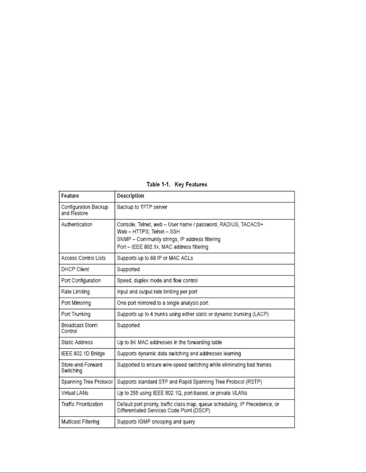
Key Features
1-1
Page 11

Description of Software Features
The switch provides a wide range of advanced performance enhancing features.
Flow control eliminates the loss of packets due to bottlenecks caused by port
saturation. Broadcast storm suppression prevents broadcast traffic storms from
engulfing the network. Port-based and protocol-based VLANs, plus support for
automatic GVRP VLAN registration provide traffic security and efficient use of
network bandwidth. CoS priority queueing ensures the minimum delay for moving
real-time multimedia data across the network. While multicast filtering provides
support for real-time network applications. Some of the management features are
briefly described below.
Configuration Backup and Restore – You can save the current configuration
settings to a file on a TFTP server, and later download this file to restore the
switch configuration settings.
Authentication – This switch authenticates management access via the console
port, Telnet or web browser. User names and passwords can be configured
locally or can be verified via a remote authentication server (i.e., RADIUS or
TACACS+). Port-based authentication is also supported via the IEEE 802.1x
protocol. This protocol uses the Extensible Authentication Protocol over LANs
(EAPOL) to request user credentials from the 802.1x client, and then verifies the
client’s right to access the network via an authentication server.
Other authentication options include HTTPS for secure management access via
the web, SSH for secure management access over a Telnet-equivalent
connection, IP address filtering for SNMP/web/Telnet management access, and
MAC address filtering for port access.
Access Control Lists – ACLs provide packet filtering for IP frames (based on
address, protocol, TCP/UDP port number or TCP control code) or any frames
(based on MAC address or Ethernet type). ACLs can be used to improve
performance by blocking unnecessary network traffic or to implement security
controls by restricting access to specific network resources or protocols.
Port Configuration – You can manually configure the speed, duplex mode, and
flow control used on specific ports, or use auto-negotiation to detect the
connection settings used by the attached device. Use the full-duplex mode on
ports whenever possible to double the throughput of switch connections. Flow
control should also be enabled to control network traffic during periods of
congestion and prevent the loss of packets when port buffer thresholds are
exceeded. The switch supports flow control based on the IEEE 802.3x standard.
Rate Limiting – This feature controls the maximum rate for traffic transmitted or
received on an interface. Rate limiting is configured on interfaces at the edge of a
1-2
Page 12

network to limit traffic into or out of the network. Traffic that falls within the rate
limit is transmitted, while packets that exceed the acceptable amount of traffic are
dropped.
Port Mirroring – The switch can unobtrusively mirror traffic from any port to a
monitor port. You can then attach a protocol analyzer or RMON probe to this port
to perform traffic analysis and verify connection integrity.
Port Trunking – Ports can be combined into an aggregate connection. Trunks
can be manually set up or dynamically configured using IEEE 802.3ad Link
Aggregation Control Protocol (LACP). The additional ports dramatically increase
the throughput across any connection, and provide redundancy by taking over the
load if a port in the trunk should fail. The switch supports up to 4 trunks.
Broadcast Storm Control – Broadcast suppression prevents broadcast traffic
from overwhelming the network. When enabled on a port, the level of broadcast
traffic passing through the port is restricted. If broadcast traffic rises above a
pre-defined threshold, it will be throttled until the level falls back beneath the
threshold.
Static Addresses – A static address can be assigned to a specific interface on
this switch. Static addresses are bound to the assigned interface and will not be
moved. When a static address is seen on another interface, the address will be
ignored and will not be written to the address table. Static addresses can be used
to provide network security by restricting access for a known host to a specific
port.
IEEE 802.1D Bridge – The switch supports IEEE 802.1D transparent bridging.
The address table facilitates data switching by learning addresses, and then
filtering or forwarding traffic based on this information. The address table supports
up to 8K addresses.
Store-and-Forward Switching – The switch copies each frame into its memory
before forwarding them to another port. This ensures that all frames are a
standard Ethernet size and have been verified for accuracy with the cyclic
redundancy check (CRC). This prevents bad frames from entering the network
and wasting bandwidth.
To avoid dropping frames on congested ports, the switch provides 8 MB for frame
buffering. This buffer can queue packets awaiting transmission on congested
networks.
Spanning Tree Protocol – The switch supports these spanning tree protocols:
Spanning Tree Protocol (STP, IEEE 802.1D) – This protocol adds a level of fault
tolerance by allowing two or more redundant connections to be created between a
pair of LAN segments. When there are multiple physical paths between segments,
1-3
Page 13

this protocol will choose a single path and disable all others to ensure that only
one route exists between any two stations on the network. This prevents the
creation of network loops. However, if the chosen path should fail for any reason,
an alternate path will be activated to maintain the connection.
Rapid Spanning Tree Protocol (RSTP, IEEE 802.1w) – This protocol reduces the
convergence time for network topology changes to about 10% of that required by
the older IEEE 802.1D STP standard. It is intended as a complete replacement for
STP, but can still interoperate with switches running the older standard by
automatically reconfiguring ports to STP-compliant mode if they detect STP
protocol messages from attached devices.
Virtual LANs – The switch supports up to 255 VLANs. A Virtual LAN is a
collection of network nodes that share the same collision domain regardless of
their physical location or connection point in the network. The switch supports
tagged VLANs based on the IEEE 802.1Q standard. Members of VLAN groups
can be dynamically learned via GVRP, or ports can be manually assigned to a
specific set of VLANs.
This allows the switch to restrict traffic to the VLAN groups to which a user has
been assigned. By segmenting your network into VLANs, you can:
• Eliminate broadcast storms which severely degrade performance in a flat
network.
• Simplify network management for node changes/moves by remotely configuring
VLAN membership for any port, rather than having to manually change the
network connection.
• Provide data security by restricting all traffic to the originating VLAN.
• Use private VLANs to restrict traffic to pass only between data ports and the
uplink ports, thereby isolating adjacent ports within the same VLAN, and allowing
you to limit the total number of VLANs that need to be configured.
Traffic Prioritization – This switch prioritizes each packet based on the required
level of service, using four priority queues with strict or Weighted Round Robin
Queuing. It uses IEEE 802.1p and 802.1Q tags to prioritize incoming traffic based
on input from the end-station application. These functions can be used to provide
independent priorities for delay-sensitive data and best-effort data.
This switch also supports several common methods of prioritizing layer 3/4 traffic
to meet application requirements. Traffic can be prioritized based on the priority
bits in the IP frame’s Type of Service (ToS) octet. When these services are
enabled, the priorities are mapped to a Class of Service value by the switch, and
the traffic then sent to the corresponding output queue.
Multicast Filtering – Specific multicast traffic can be assigned to its own VLAN to
ensure that it does not interfere with normal network traffic and to guarantee
real-time delivery by setting the required priority level for the designated VLAN.
The switch uses IGMP Snooping and Query to manage multicast group
1-4
Page 14
registration.
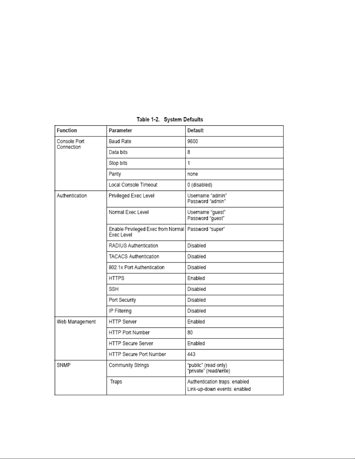
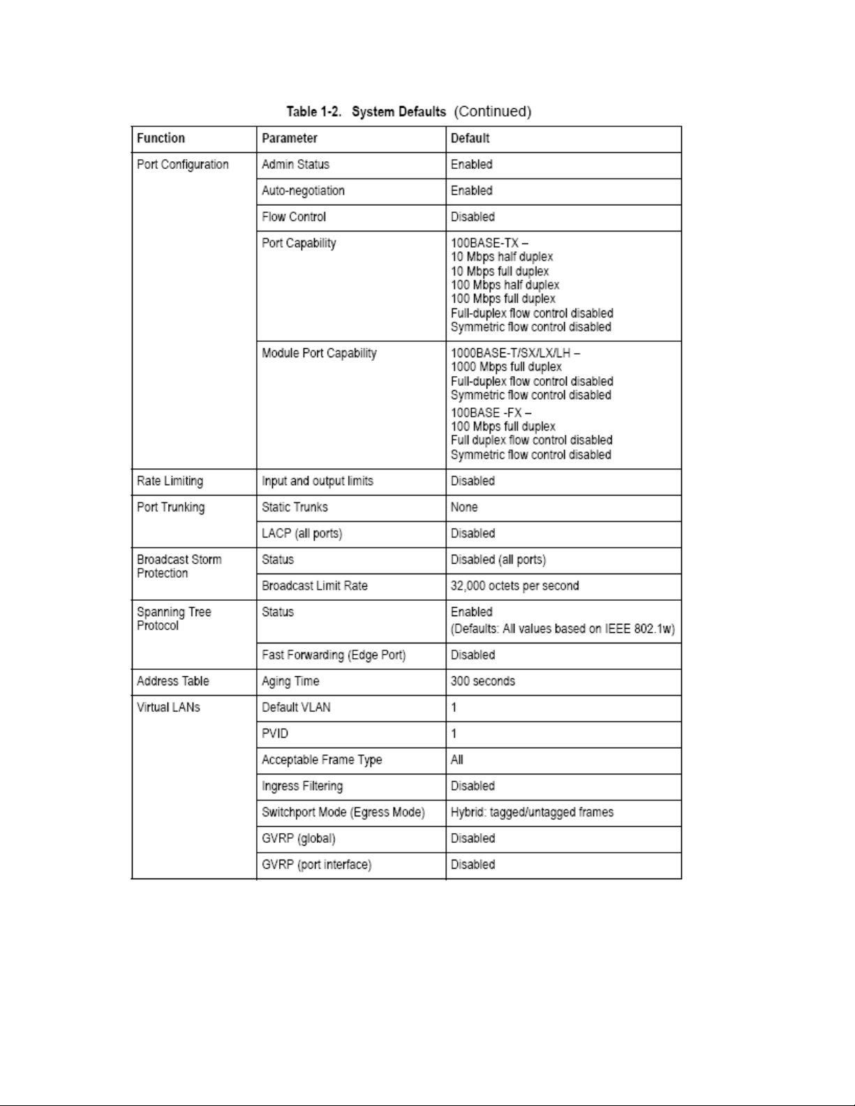
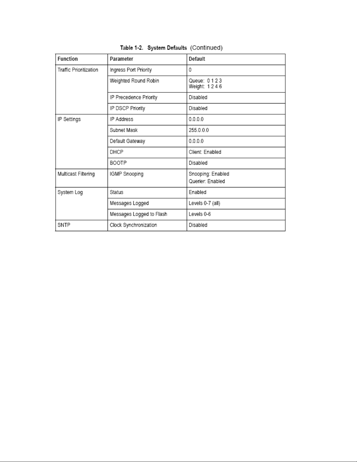
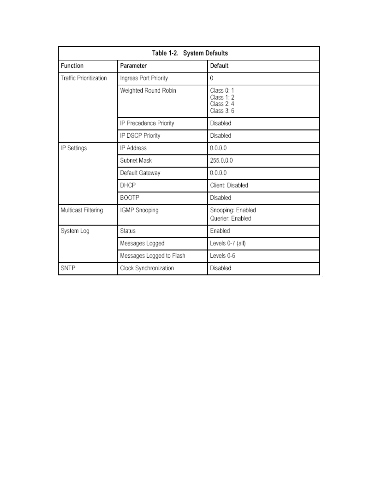
System Defaults
The switch’s system defaults are provided in the configuration file
“Factory_Default_Config.cfg.” To reset the switch defaults, this file should be set
as the startup configuration file (page 3-21).
The following table lists some of the basic system defaults.
1-5
Page 15
1-6
Page 16
1-7
Page 17
1-8
Page 18

2 Chapter: Initial Configuration
Connecting to th
e Switch
Configuration Options
The switch includes a built-in network management agent. The agent offers a
variety of management options, including SNMP, RMON and a Web-based
interface. A PC may also be connected directly to the switch for configuration and
monitoring via a command
ote: The IP address for this switch is unassigned by default. To change this
N
address, see “Setting an IP Address” on page 2-4.
The switch’s HTTP Web agent allows you to configure switch parameters, monitor
port connections, a
etscape Navigator version 6.2 and higher or Microsoft IE version 5.0 and higher.
N
The switch’s Web management interface can be accessed from any c
ttached to the network.
a
The CLI program can be accessed by a direct connection to the RS-232 serial
console por
The switch’s management agent also supports SNMP
Management Protocol). This SNMP agent permits the switch to b
any system in the network usin
OpenView.
The switch’s Web interface, CLI con
you to perform the following management functions:
• Set user names and passwords for up to 16 users
• Set an IP interface for a management VLAN
• Configure SNMP parameters
• Enable/disable any port
• Set the speed/duplex mode fo
• Configure the bandwidth of any port by limiting input or output rates
• Configure port access
• Filter packets using Access Control Lists(ACLs)
• Configure
• Enable GVRP automatic VLAN registration
t on the switch, or remotely by a Telnet connection over the network.
up to 255 IEEE 802.1Q VLANs
nd display statistics using a standard Web browser such as
line interface (CLI).
omputer
(Simple Network
e managed from
g network management software such as HP
figuration program, and SNMP agent allow
r any port
through IEEE 802.1x security or static address filtering
2-1
Page 19

• Configure IGMP multicast filtering
• Upload and download system firmware via TFTP
• Upload and download switch configuration files via TFTP
• Configure Spanning Tree pa
rameters
• Configure Class of Service (CoS) priority queuing
• Configure up to 4 static or LACP trunks
• Enable port mirroring
• Set broadcast storm control on any port
• Display system information and statistics
Required Connections
he switch provides an RS-232 serial port that enables a connection to a PC or
T
terminal for monitoring and configuring the switch. A null-mode
rovided with the switch.
p
Attach a VT100-compatible terminal, or a PC running a terminal emulation
program to the switch. You can use the console cable provided with this package,
or use a null-modem cable that complies with the wiring assignments shown in the
Installation Guide.
o connect a terminal to the console port, complete the following steps:
T
1. Connect the console cable to the serial port on a terminal, or a PC running
terminal emulation software, and tighten the ca
ptive retaining screws on the DB-9
connector.
2. Connect the other end of th
3. Make sure the terminal emulat
e cable to the RS-232 serial port on the switch.
ion software is set as follows:
• Select the appropriate serial port (COM port 1 or COM port 2).
• Set the baud rate to 9600bp
• Set the data format to 8 dat
s.
a bits, 1 stop bit, and no parity.
• Set flow control to none.
• Set the emulation mode to VT100.
• When using HyperTerminal, select Terminal keys, not Windows keys.
Notes: 1. When using HyperTerminal with Microsoft® Windows® 2000, make
sure that you have Windows 2000 Service Pack 2 or later installed. Windows
2000 Service Pack 2 fixes the problem of arrow keys not functioning in
yperTerminal’s VT10H
0 emulation. See www.microsoft.com for information on
Windows 2000 service packs.
2. Refer to “Line Commands” on page 4-10 for a complete description of console
configuration options.
3. Once you have set up the terminal correctly, the console login screen will be
displayed.
For a description of how to use the CLI, see “Using the Command Line Interface”
m console cable is
2-2
Page 20

on page 4-1. For a list of all the CLI commands and detailed information on using
the CLI, refer to “Command Groups” on page 4-9.
Remote Connections
Prior to accessing the switc
first configure it with a valid IP address, subnet mask, and default gateway using a
console connection, DHCP or BOOTP protocol.
The IP address for this switch is unassigned by default. To manually configure this
address or enable dynamic addre
etting an IP Address” on page 2-4.
“S
Note: This
After configuring the switch’s IP parameters, you can access the onboard
configuration program from anywh
configuration program can be accessed
to the network. The switch can also be managed by any computer using a web
browser (Internet Explorer 5.0 or above, or Netscape Na
from a network computer using SNMP network management software.
Note: The onboard program only provides access to basic configuration functions.
To access the
SNMP-based network management software.
switch supports four concurrent Telnet sessions.
full range of SNMP management functions, you must use
h’s onboard agent via a network connection, you must
ss assignment via DHCP or BOOTP, see
ere within the attached network. The onboard
using Telnet from any computer attached
vigator 6.2 or above), or
Basic Configuration
Console Connection
The CLI program provides two different command levels — normal access level
(Normal Exec) and privileged access level (Privileged Exec). The commands
available at the Normal Exec level are a limited subset of those available at the
Privileged Exec level and allow you to only display information and use basic
utilities. To fully configure the switch param
Privileged Exec level.
Access to both CLI levels are controlled by user names and passwords. The
switch has a default user name and password for each level. To log into the CLI at
the Privileged Exec level using the default user name and password, perform
hese steps: t
1. To initiate your console connection, press <Enter>. T
Verification” procedure starts.
eters, you must access the CLI at the
he “User Access
2-3
Page 21

2. At the Username prompt, enter “admin.”
3. At the Password prompt, also enter “admin.” (The password characters are not
isplayed on the console screen.)
d
4. The session is opened a
you have access at the Privileged
etting Passwords
S
Note: If this is your first time to log into the CLI program, you should define new
passwords for both default user names using the “username” command, rec
them and put them in a safe place.
Passwords can consist of up to 8 alphanumeric characters and are case
sensitive.
To prevent unauthorized access to the switch, set the passwords as follows:
1. Open the console interface with the
access the Privileged Exec level.
2. Type “configure” and press <Enter>.
3. Type “username guest password 0 password,” for the Normal Exec level,
where password is your new password. Press <Enter>.
4. Type “username admin password 0 password,” for the Privileged Exec level,
where password is your new password. Press <Enter>.
Note: ‘0’ specifies the password in plain text, ‘7’ specifies the password in
encrypted form.
nd the CLI displays the “Console#” prompt indicating
Exec level.
ord
default user name and password “admin” to
Setting an IP Address
You must establish IP address information for the switch to obtain management
access throu
Manual — You have to input the information, including IP address and subn
will also need to specify the default gateway router.
Dynamic — The switch sends IP configuration requests to BOOTP or DHCP
address allocation servers on the network.
2-4
gh the network. This can be done in either of the following ways:
switch, yomask. If your management station is not in the same IP subnet as the
et
u
Page 22

Manual Configuration
You can manually assign an IP address to the switch. You may also need to
specify a default gateway that resides between this device and management
stations that exist on another network segment. Valid IP addresses consist of four
decimal numbers, 0 to 255, separated by periods. A
nything outside this format will
not be accepted by the CLI program.
Note: The IP address for this switch is unassigned by default.
Before you can assign an IP address to the switch, you must obtain the following
information from your network administrator:
IP address for the switch
•
• Default gateway for the network
• Network mask for this network
To assign an IP address to the switch, complete the following steps:
1. From the Privileg
ed Exec level global configuration mode prompt, type
“interface vlan 1” to access the interface-configuration mode. Press <Enter>.
2. Type “ip address ip-address netmask,” where “ip-address” is the switch IP
address and “netmask” is the network mask for the network. Press <Enter>.
3. Type “exit” to return
. To set the IP address of the default gateway for the network to which the switch
4
belongs, type “ip default
to the global configuration mode prompt. Press <Enter>.
-gateway gateway,” where “gateway” is the IP address of
the default gateway. Press <Enter>.
Dynamic Configuration
If you select the “bootp” or “dhcp” option, IP will be enabled but will not function
until a BOOTP or DHCP reply has been rec
p dhcp restart” command to start broadcasting service requests. Requests will
“i
be sent periodically in an effort to obtain IP configuration info
and DHCP values can include the IP address, subnet mask, and
eived. You therefore need to use the
rmation. (BOOTP
default
gateway.)
If the “bootp” or “dhcp” option is
saved to the startup-config file (step 6), then the
switch will start broadcasting service requests as soon as it is powered on.
To automatically configure the switch by communicating with BOOTP or DHCP
address allocation servers on the network, complete the following steps:
1. From the Global Configuration mode prompt, type “interface vlan 1” to access
the interface-configuration mode. Press <Enter>.
2-5
Page 23
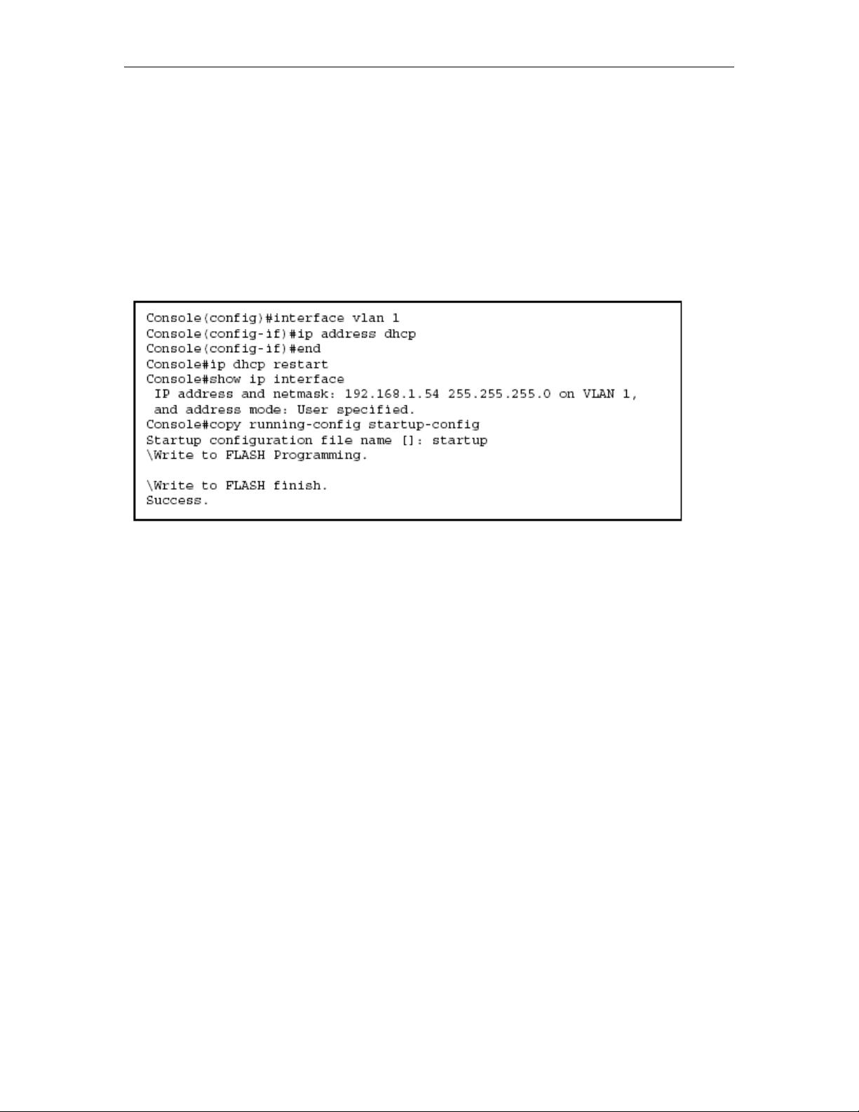
2. At the interface-configuration mode prompt, use one of the following
commands:
To obtain IP settings via DHCP, type “ip address dhcp” and press <Enter>.
•
• To obtain IP settings via BOOTP, type “ip address bootp”
and press <Enter>.
3. Type “end” to return to the Privileged Exec mode. Press <Enter>.
4. Type “ip dhcp restart” to begin broadcasting service requests. Press <Enter>.
5. Wait a few minutes, and then check the IP configuration settings by typing the
“show ip interface” command. P
ress <Enter>.
6. Then save your configuration changes by typing “copy running-config
startup-config.” Enter the startup file name and press <Enter>.
Enabling SNMP Management Access
The switch can be configured to accept management commands from Simple
Network Management Protocol (SNMP) applications such as HP OpenView. You
can configure the switch to (1) respond to SNMP requests or (2) generate SNMP
traps.
When SNMP management stations send requests to the switch (either to return
information or to set a par
the specified parameter. The switch can also be configured to send information to
SNMP managers (without being requested by the managers) through trap
messages, which inform the manager that certain events have occurred.
Community Strings
Community strings are used
well as to authorize SNMP stations to receive trap messages from the switch. You
therefore need to assign community strings to specified users or user groups, and
set the access level.
The default strings are:
• public - with read-only access. Authorized management stations are only able
to retrieve MIB objects.
• private - with read-write access. Authorized management stations are able to
ameter), the switch provides the requested data or sets
to control management access to SNMP stations, as
2-6
Page 24
both retrieve and modify MIB objects.
Note: If you do not intend to utilize SNMP, we recommend that you delete both of
the default community strings. If there are no community strings, then SNMP
management access to the sw
itch is disabled.
To prevent unauthorized access to the switch via SNMP, it is recommended that
you change the default community strings.
o configure a community string, complete the following steps:
T
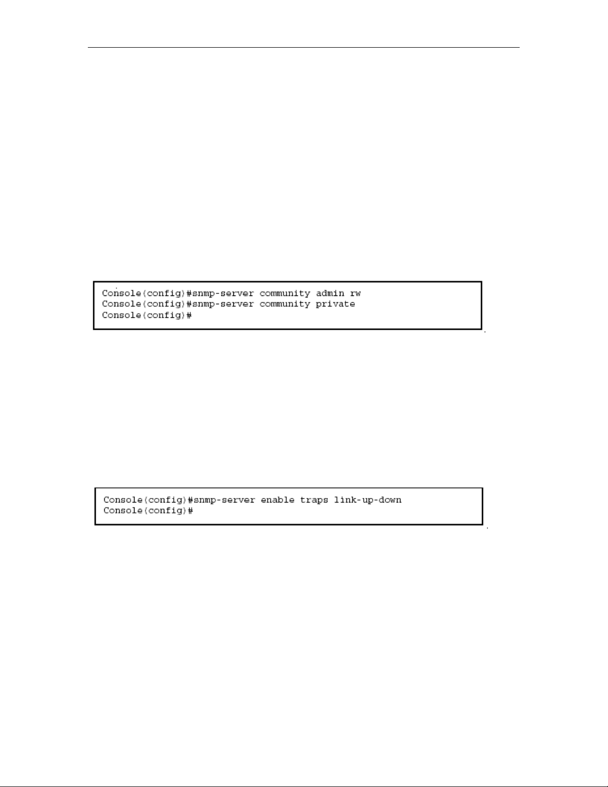
1. From the Privileged Exec level global configuration mode prompt, type
“snmp-server community string mode,” where “string” is the community access
string and “mode” is rw (read/write) or ro (read only). Press <
e default mode is read only.)
th
Enter>. (Note that
2. To remove an existing string, simply type “no snmp-server community string,”
where “string” is the community access string to remove. Press <Enter>.
Trap Receivers
You can also specify SNMP stations that are to receive traps from the switch.
To configure a trap receiver, complete the following steps:
1. From the Privileged Exec level global configuration mode prompt, type
“snmp-server host host-address community-string,” where “host-address” is the
IP address for the trap receiver and “community-string” is the string associated
with that host. Press <Enter>.
2. In order to configure the switch to send SNMP notifications, you must enter at
least one snmp-server enable traps command. Type “snmp-server enable traps
type,” where “type” is either authentication or link-up-down. Press <Enter>.
Saving Configuration Settings
Configuration commands only modify the running configuration file and are not
saved when the switch is rebooted. To save all your configuration changes in
nonvolatile storage, you must copy the running configuration file to the start-up
configuration file using the “copy” command.
To save the current configuration settings, enter the following command:
1. From the Privileged Exec mode prompt, type “copy running-config
startup-config” and press <Enter>.
2. Enter the name of the start-up file. Press <Enter>.
2-7
Page 25

Managing System Files
The switch’s flash memory supports three types of system files that can be
managed by the CLI program, Web interface, or SNMP. The switch’s file system
allows files to be uploaded and downloaded, copied, deleted, and set as a start-up
file.
The three types of files are:
Configuration — This file stores system configuration information and is
•
created when configuration settings are saved. Saved configuration files can be
selected as a system start-up file or can be uploaded via TFTP to a server for
backup. A file named “Factory_Default_Config.cfg” contains a
ettings and cannot be deleted from the system. See “Saving or Restoring
s
ll the system default
Configuration Settings” on page 3-19 for more information.
• Operation Code — System s
oftware that is executed after boot-up, also known
as run-time code. This code runs the switch operations and provides the CLI and
Web management interfaces. See “Managing Firmware” on page 3-16 for more
information.
• Diagnostic Code — Software that is run during system boot-up, also known as
POST (Power On Self-Test).
Due to the size limit of the flash memory, the switch supports only two operation
code files. However,
you can have as many diagnostic code files and
configuration files as available flash memory space allows.
In the system flash memory, one file of each type must be set as the start-up file.
During a system boot, the diagnostic and operation code files set as the start-up
file are run, and then the start-up configuration file is loaded.
Note that configuration files should be downloaded using a file name that reflects
the contents or usage of the file settings. If you download directly to the
running-config, the system will reboot, and the settings will have to be copied from
the running-config to a permanent file.
2-8
Page 26

3 Chapter : Configuring the Switch
Using the Web Int
This switch provides an embedded HTTP
can configure the switch and view statistics to monitor network activity. The Web
agent can be accessed by any computer on the network using a standard Web
browser (Internet Explorer 5.0 or above, or Netscape Navigator 6.2 or above).
Note: You can also use the Command Line Interface (CLI) to manage the switch
over a seri
sing the CLI, refer to Chapter 4: “Command Line Interface.”
u
Prior to accessing the swi r, be sure you have first
performedthe following tasks:
1. Configure the switch with a valid IP address, subnet mask, and default gateway
using an out-of-band serial connection, BOOTP or DHCP protocol. (See “Setting
an IP Address” on page 2-4.)
2. Set user names and passwords using an out-of-band serial connection. Access
to the Web agent is controlled by the same user names and passwords as the
onboard configuration program. (See “Setting Passwords” on page 2-4.)
3. After you enter a user name and password, you will have access to the system
configuration program.
Notes: 1. You are allowed three attempts to enter the correct password; on the
third failed attempt the current connection is terminated.
2. If you log into the Web interface as guest (Normal Exec level), you can view the
configuration settings or change the guest password. If you log in as “admin”
(Privileged Exec level), you can change the settings on any page.
3. If the path between your management station and this switch does not pass
through any device that uses the Spanning Tree Algorithm, then you can set the
switch port attached to your management station to fast forwarding (i.e., enable
Admin Edge Port) to improve the switch’s response time to management
commands issued through the web interface. See “Configuring Interface Settings”
on page 3-101
al connection to the console port or via Telnet. For more information on
erface
Web agent. Using a Web browser you
tch from a Web browse
3-1
Page 27
Navigating the Web Browser Interface
To access the web-browser interface you must first enter a user name and
password. The administrator has Read/Write access to all configuration
parameters and statistics. The default user name and password for the
administrator is “admin
Home Page
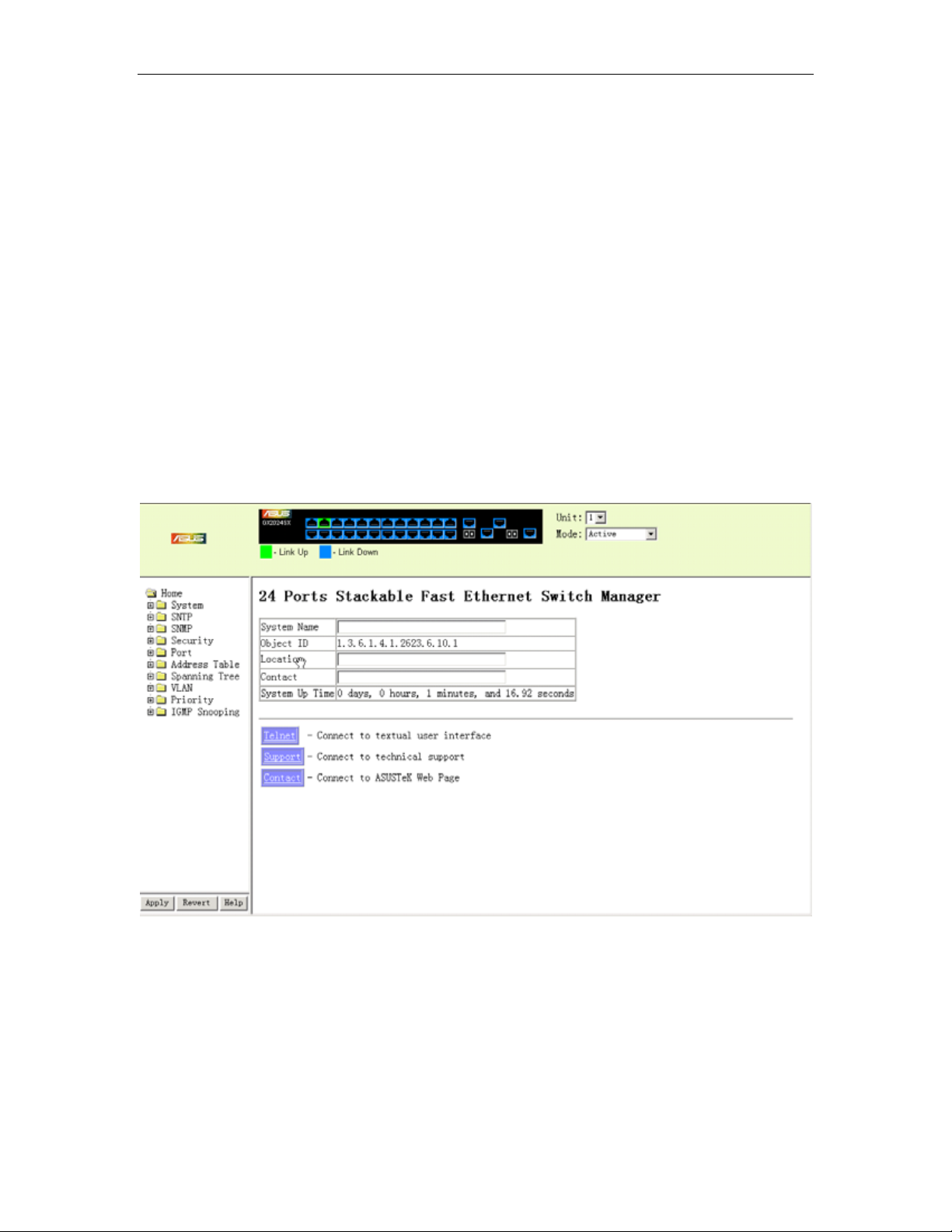
When your web browser connects with the switch’s web agent, the home page is
displayed as shown below. The home page displays the Main Menu on the left
side of the screen and System Information on the right side. The Main Menu links
are used to navigate to other menus, and display configuration parameters and
statistics.
.”
Figure 3-1. Home Page
3-2
Page 28
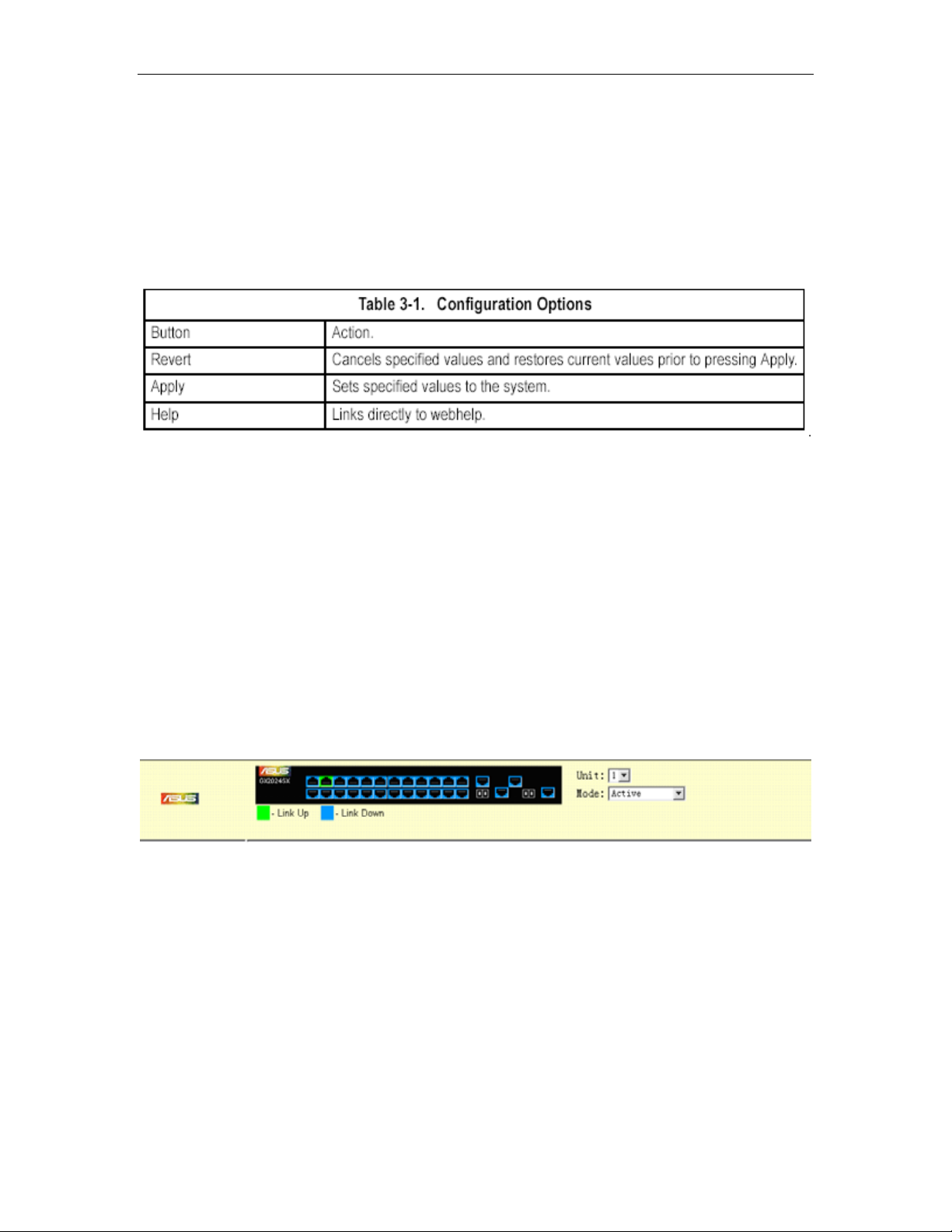
Configuration Options
Configurable parameters have a dialog box or a drop-down list. Once a
configuration change has been made on a page, be sure to click on the Apply
button to confirm the new setting. The following table summarizes
configuration buttons.
Notes: 1. To ensure proper screen refresh, be sure that Internet Explorer 5.x is
configured as follows: Under the menu “Tools / Internet Options / General /
Temporary Internet Files / Settings,” the setting for item “Check for newer
versions of stored pages” should be “Every visit to the page.”
2. When using Internet Explorer 5.0, you may have to manually refresh the screen
after making configuration changes by pressing the browser’s refresh button.
the web page
Panel Display
The web agent displays an image of the switch’s ports. The Mode can be set to
display different information for the ports, including Active (i.e., up or down),
Duplex (i.e., half or full duplex, or Flow Control (i.e., with or without flow control).
Clicking on the image of a port opens the Port Configuration page as described on
page 3-66.
Figure 3-2. Ports Panel Display
3-3
Page 29

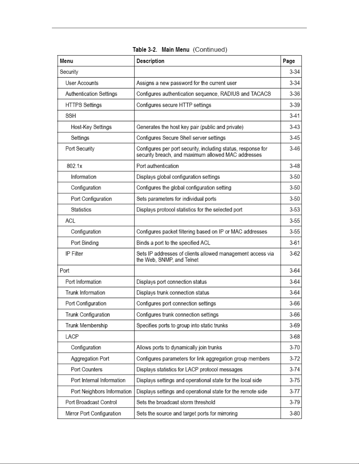
Main Menu
Using the onboard web agent, you can define system parameters, manage and
control the switch, and all its ports, or monitor network conditions. The following
table briefly describes the selections available from this program.
3-4
Page 30
3-5
Page 31

3-6
Page 32

3-7
Page 33

3-8
Page 34

Basic Configuration
D splayin
i g System Information
You can easily identify the system b
contact information.
Field Attributes
• System Name – Name assigned to the switch system.
• Object ID – MIB II object ID for switch’s network management subsystem.
• Location – Specifies the system location.
• Contact – Administrator responsible for the system.
• System Up Time – Length of time the management agent has been up.
These additional parameters are displayed for the CLI.
• MAC Address – The physical layer address for this switch.
• Web server – Shows if management access via HTTP is enabled.
• Web server port – Shows the TCP port number used by the web interface.
• Web secure server – Shows if manageme
• Web secure server port – Shows the TCP port used by the HTTPS interface.
• Telnet server – Shows if management access via Telnet is enabled.
• Telnet server port – Shows the TCP port used by the Telnet interface.
• Jumbo Frame – Shows if jumbo frames are enabled.
• POST result – Shows results of the power-on self-test
Web – Click System, System Information. Specify the system name, location, and
contact information for the system administrator, then click Apply. (This page also
includes a Telnet button that allows access to the Command Line Interf
Telnet.)
y displaying the device name, location and
nt access via HTTPS is enabled.
ace via
Figure 3-3. Displaying System Information
3-9
Page 35

CLI – Specify the hostname, location and contact information.
Displaying Switch Hardware/Software Versions
Use the Switch Information page to di
for the main board ower status of the
and management software, as well as the p
system.
Field Attributes
Main Board
• Serial Number – The serial number of the switch.
• Number of Ports – Number of built-in RJ-45 ports and ex
• Hardware Version – Hardware version of the main board.
• Internal Power Status – Displays the status of the internal power supply.
• Redundant Power Status* – Displays the status of the redundant power
Management Software
• Loader Version – Version number of loader code.
• Boot-ROM Version – Version of Power-On Self-Test (POST) and boot code.
• Operation Code Version – Version number of runtime code.
• Role – Shows that this switch is operating as Master (i.e., operating
stand-alone).
splay hardware/firmware version numbers
pansion ports.
3-10
Page 36

Expansion Slot
• Expansion Slot 1/2 –Combination RJ-45/SFP ports.
These additional parameters are displayed for the CLI.
• Unit ID – Unit number in stack.
• Redundant Power Status – Displays the status of the redundant power supply.
Web – Click System, Switch Information.
Figure 3-4. Displaying Switch Information
version information. CLI – Use the following command to display
3-11
Page 37

Displaying Bridge Extension Capabilities
The Bridge MIB includes extensions for managed devices that support Multicast
Filtering, Traffic Classes, and Virtual LANs. You can access these extensions to
display default settings for the key variables.
Field Attributes
• Extended Multicast Filtering Services – This switch does not support the
filtering of individual multicast addresses based on GMRP (GARP Multicast
Registration Protocol).
• Traffic Classes – This switch provides mapping of user priorities to multiple
traffic classes. (Refer to “Class of Service Configuration” on page 3-122.)
• Static Entry Individual Port – This switch allows static filtering for unicast and
multicast addresses. (Refer to “Setting Static Addresses” on page 3-88.)
• VLAN Learning – This switch uses Independent VLAN Learning (IVL), where
each port maintains its own filtering database.
• Configurable de the default
ort VLAN ID (PVID used in frame tags) and egress status (VLAN-Tagged or
P
Untagged) on each port. (Refer to “VLAN Configuration” on page 3-103.)
• Local VLAN Capable – This switch does not support multiple local bridges (i.e.,
multiple spanning trees).
• MRP – GARP Multicast Registration Protocol (GMRP) allows network devices
G
to register endstat t support GMRP;
uses the Internet Group Management Protocol (IGMP) to provide automatic
it
multicast filtering.
Web – Click System, Bridge Extension Configuration.
PVID Tagging – This switch allows you to overri
ions with multicast groups. This switch does no
Figure 3-5. Displaying Bridge Extension Configuration
CLI – Enter the following command.
3-12
Page 38

Setting the Switch’s IP Address
This section describes how to configure an IP interface for management access
over the network. The IP address for this switch is unassigned by default. T
manually configure an address, you need to change the switch’s default settings
(IP address 0.0.0.0 and netmask 255.0.0.0) to values that are compatibl
your network. You may also need to a establish a default g
ateway between the
switch and management stations that exist on another network segment.
You can manually configure a specific IP address, or direct the device to
address from a BOOTP or DHCP server. Valid IP addresses cons
decimal numbers, 0 to 255, separated by periods. Anything outsid
e this format will
obtain an
ist of four
not be accepted by the CLI program.
Command Attributes
• Management VLAN – ID of the configured VLAN (1-4094, no leading zeroes).
By default, all ports on the switch are members of VLAN 1. However, the
management station can be attached to a po
rt belonging to any VLAN, as long as
that VLAN has been assigned an IP address.
• IP Address Mode – Specifies whether IP functionality is enabled via manual
configuration (Static), Dynamic
Protocol (BOOTP). If DHCP/BOOTP is enabled, IP will
as been received from the server. Requests will be broadcast periodically by the
h
Host Configuration Protocol (DHCP), or Boot
not function until a reply
switch for an IP address. (DHCP/BOOTP values can include the IP address,
subnet mask, and default gateway.)
• IP Address – Address of the VLAN interface that is allowed management
access. Valid IP addresses consist of four numbers, 0 to 255, separated by
periods.
Subnet Mask – This mask identifies the host address bits used for routing to
•
(Default: 0.0.0.0)
specific subnets. (Default: 255.0.0.0)
• Gateway IP address – IP address of the gateway router between this device
and management stations that exist on other network segments. (Default: 0.0.0.0)
• MAC
Address – The physical layer address for this switch.
• Restart DHCP – Releases the current IP address and requests a new IP
address from the DHCP server.
o
e with
3-13
Page 39

Manual Configuration
Web – Click System, IP Configuration. Select the VLAN through which the
management station is attached, set the IP Address Mode to “Static,” enter the IP
address, subnet mask and gateway, then click Apply.
Figure 3-6. IP Configuration
CLI – Specify the management interface, IP address and default gateway.
Using DHCP/BOOTP
If your network provides DHCP/BOOTP services, you can configure the switch to
be dynamically configured by these services.
Web – Click System, IP Configuration. Specify the VLAN to which the
management station is attached, set the IP Address Mode to Static, DHCP or
BOOTP. Click Apply to save your changes. Then click Restart DHCP to
t aimmediately request a new address. Note that the switch will also broadcas
request for IP configuration settings on each po
wer reset.
3-14
Page 40

Figure 3-7. IP Configuration using DHCP
Note: If you lose your management connection, use a console connection and
enter “show ip interface” to determine the new switch address.
CLI – Specify the management interface, and set the IP address mode to DHCP
or BOOTP, and then enter the “ip dhcp restart” command.
Renewing DCHP – DHCP may lease addresses to clients indefinitely or for a
specific period of time. If the address expires or the switch is moved to another
network segment, you will lose management access to the switch. In this case,
you can reboot the switch or submit a client request to restart DHCP service via
the CLI.
Web – If th
e address assigned by DHCP is no longer functioning, you will not be
able to renew the IP settings via the web interface. You can only restart DHCP
service via the web interface if the current
address is still available.
CLI – Enter the following command to restart DHCP service.
Managing Firmware
You can upload/download firmware to or from a TFTP server. By saving runtime
3-15
Page 41

code to a file on a TFTP server, that file can later be downloaded to the switch to
restore operation. You can also set the switch to use new firmware without
overwriting the previous version. The switch also allows a runtime code file to be
copied to or from another switch unit in the stack.
Command Attributes
• File Transfer Method – The firmware copy operation includes these options:
- file to file – Copies a file within the switch directory, assigning it a new name.
- file to tftp – Copies a file from the switch to a TFTP server.
- tftp to file – Copies a file from a TFTP server to the switch.
- file to unit – Copies a file from this switch to another unit in the stack.
- unit to file – Copies a file from another unit in the stack to this switch.
• TFTP Server IP Address – The IP address of a TFTP server.
• File Name – The file name should not contain slashes (\ or /), the leading letter
of the file name should not be a period (.), and the maximum length for file names
on the TFTP server is 127 characters or 31 characters for files on the switch.
(Valid characters: A-Z, a-z, 0-9, “.”, “-”, “_”)
• Source/Destination number.
Unit – Specifies the switch stack unit
Note: Up to two copies of the system software (i.e., the runtime firmware) can be
stored in the file directory on the switch. The currently designated startup version
of this file cannot be deleted.
Downloading System Software from a Server
When downloading r
replace the current im
untime code, you can specify the destination file name to
age, or first download the file using a different name from
the current runtime code file, and then set the new file as the startup file.
Web – Click System, File, Copy. Select “tftp to file” from the drop-down menu.
Select “opcode” as the file type, then enter the IP address of the TFTP server, set
the file type to “opcode,” enter the file name of the software to download, sel
a file on the switch to ov
erwrite or specify a new file name, then click Apply. If you
ect
replaced the current firmware used for startup and want to start using the new
operation code, reboot the system via the System/Reset menu.
3-16
Page 42

Figure 3-8. Operation Code Image File Transfer
If you download to a new destination file, select the file from the drop-down box for
the operation code used at startup, and click Apply. To start the new firmware,
reboot the system via the System/Reset menu.
Figure 3-9. Select Start-Up Operation File
To delete a file select System,
File, Delete. Select the file name from the given list
by checking the tick box and click Apply. Note that the file currently designated as
the startup code cannot be deleted.
3-17
Page 43

Figure 3-10. Deleting Files
CLI – To download new firmware form a TFTP server, enter the IP address of the
TFTP server, select “opcode” as the file type, then enter the source and
destination file names. When the file has completed the download, set the new file
to start up the system and then restart the switch.
To start the new firmware, enter the “reload” command or reboot the system.
Saving or Restoring Configuration Settings
You can upload/download configuration settings to/from a TFTP server or copy
les to and from switch units in a stack. The configuration files can be later
fi
downloaded to restore the switch’s settings.
ommand Attributes
C
• File Transfer Method – The configuration copy operation includes these options:
- file to file – Copies a file within the switch directory, assigning it a new name.
- file to running-config – Copies a file in the switch to the running configuration.
- file to startu uration.
- file to tftp – Copies a file from the switch to a TFTP server.
- running-config to file – Copies the running configuration to a file.
- running-config to startup-config – Copies the running config to the startup config.
- running-config t
- startup-config to file – Copies the startup configuration to a file on the switch.
- startup-config to running-config – Copies the startup config to the running config.
- startup-config to tftp – Copies the startup configuration to a TFTP server.
- tftp to file – Copies a file from a TFTP server to the switch.
- tftp to running-config – Copies a file from a TFTP server to the running config.
- tftp to startup-config – Copies a file from a TFTP server to the startup config.
- file to unit – Copies a file from this switch to another unit in the stack.
- unit to file – Copies a file from
• TFTP Server IP Address – The IP address of a TFTP server.
• File Type – Specify config (configuration) to copy configuration settings.
• File Name — The file name should not contain slashes (\ or /),
p-config – Copies a file in the switch to the startup config
o tftp – Copies the running configuration to a TFTP server.
another unit in the stack to this switch.
the leading letter
3-18
Page 44

of the file name should not be a period (.), and the maximum length for file names
on the TFTP server is 127 characters or 31 characters for files on the switch.
(Valid characters: A-Z, a-z, 0-9, “.”, “-”, “_”)
• Source/Destination Unit – Specifies the switch stack unit number.
Note: The maximum number of user-defined configuration files is limited only by
available flash memory space.
Downloading Configuration Settings from a Server
You can download the configuration file under a new file name and then set it as
the startup file, or you can specify the current startup configuration file as the
destination fi
le to directly replace it. Note that the file “Factory_Default_Config.cfg”
can be copied to the TFTP server, but cannot be used as the destination on the
switch.
Web – Click System, F
ile, Copy. Select “tftp to startup-config” or “tftp to file” and
enter the IP address of the TFTP server. Specify the name of the file to download
and select a file on the switch to overwrite or specify a new file name, then cli
ck
Apply.
Figure 3-11. Copy Configuration Setting
If you download to a new file name using “tftp to startup-config” or “tftp to file,” the
file is automatically set as the start-up configuration file. To use the new settings,
reboot the system via the System/Reset menu.
Note that you can also select any configuration file as the start-up configuration by
using the System/File/Set Sta
3-19
rt-Up page.
Page 45

Figure 3-12. Setting the Startup Configuration Settings
CLI – Enter the IP address of the TFTP server, specify the source file on the
server, set the startup file name on the switch, and then restart the switch.
To select another configuration file as the start-up configuration, use the boot
system command and then restart the switch.
Console Port Settings
You can access the onboard configuration program by attaching a VT100
compatible device to the switch’s serial console port. Management access
through the console port is controlled by various parameters, including a
password, timeouts, and basic communication settings. These parameters can be
configured via the Web or CLI interface.
Command Attributes
• Login Timeout – Sets the interval that the system waits for a user to log into the
CLI. If a login attempt is not detected within the timeout interval, the connection is
terminated for the session. (Range: 0-300 seconds; Default: 0)
• Exec Tim
detected. If user inp
session is terminated. (Range: 0-65535 seconds; Default: 0 seconds)
eout – Sets the interval that the system waits until user input is
ut is not detected within the timeout interval, the current
3-20
Page 46

• Password Threshold – Sets the password intrusion threshold, which limit s the
number of failed logon
attempts. When the logon attempt threshold is reached,
the system interface becomes silent for a specified amount of time (set by the
Silent Time parameter) before allowing the next logon attempt. (Range: 0-120;
Default: 3 attempts)
• Silent Time – Sets the amount of time the management console is inaccessible
after the number of unsuccessful logon attempts has been exceeded. (Ran
ge:
0-65535; Default: 0)
• Data Bits – Sets the number of data bits per character that are interpreted
andgenerated by the console port. If p
arity is being generated, specify 7 data bits
per character. If no parity is required, specify 8 data bits per character. (Default: 8
bits)
• – Defines the generation of a parity bit. Communication protocols
Parity
providedby some termin it setting. Specify Even,
dd, or None. (Default: None)
O
als can require a specific parity b
• Speed – Sets the terminal line’s baud rate fo r transmit (to terminal) and receive
(from terminal). Set the speed to match the baud
rate of the device connected to
the serial port or specify “Auto.” (Default: 9600 bps)
• Stop Bits – Sets the number of the stop bits transmitted per byte. (Range: 1-2;
Default: 1 stop bit)
• Password* – Specifies a password for the line connection. When a connection
is started on a line with password protection, the system prompts for the password.
If you enter the correct password, the system shows a prompt. (Default: No
password)
• Login* – Enables password checking at login. You can select authentication by
a single global password as configured for the Password parameter, or by
passwords set up for specific user-name accounts (the default).
* CLI only.
Web – Click System, Line, Console. Specify the console port connection
parameters as required, then click Apply.
3-21
Page 47

Figure 3-13. Console Port Settings
CLI – Enter Line Configuration mode for the console, the
n specify the connection
parameters as required. To display the current console port settings, use the
show line command from the Normal Exec level.
Telnet Settings
You can access the onboard configuration program over the network using Telnet
(i.e., a virtual terminal). Management access via Telnet can be enabled/disabled
and other various parameters set, including the TCP port number, timeouts, and a
password. These parameters can be configured via the Web or CLI interface.
utes Command Attrib
• Telnet Status – Enables or disables Telnet access to the switch. (Default:
Enabled)
• Telnet Port Number – Sets the TCP port number for Telnet on the switch.
(Default: 23)
Login Timeout – Sets the interval that the sy• stem waits for a user to log into the
CLI. If a login attempt is not detected within the timeout interval, the connection is
s) terminated for the session. (Range: 0-300 seconds; Default: 300 second
• r input is
detected. If user input t interval, the current
ession is terminated. (R 600 seconds)
Password Threshold – Sets the password intrusion threshold, which limits the
•
– Sets the interval that the system waits until useExec Timeout
is not detected within the timeou
ange: 0-65535 seconds; Default: s
3-22
Page 48

number of failed logon attempts. When the logon attempt threshold is reached,
the system interface becomes silent for a specified amount of time (set by the
Silent Time parameter) before allowing the next logon attempt.
(Range: 0-120; Default: 3 attempts)
• Password* – Specifies a password for the line connecti
is started on a line with password protection, the system pr
on. When a connection
ompts for the password.
If you enter the correct password, the system shows a prompt. (Default: No
password)
• Login* – Enables password checking at login. You can select authentication by
a single global password as configured for the Password parameter, or by
passwords set up for specific user-name accounts (Default: Local).
Web – Click System, Line, Telnet. Specify the connection parameters for Telnet
. access, then click Apply
Figure 3-14. Enabling Telnet
CLI – Enter Line Configuration mode for a virtual terminal, then specify the
c nnection parameters as required. To display theo current virtual terminal settings,
use the show line command from the Normal Exec level.
3-23
Page 49

Configuring Event Logging
The switch allows you to control the logging of error messages, including the type
of events that are recorded in switch memory, logging to a remote System Log
(syslog) server, and dis
System Logs Configuration
The system allows you to enable or disable event logging, and specify which
levels are logged
to RAM or flash memory.
Severe error messages that are logged to flash memory are p
in the switch to assist in troubleshooting net
can be stored in the flash memor
when the available log memory (256 kilobyte
The System Logs page allows you to configure and limit system messages
are logged to flash or RAM memory. The default is for even
gged to flash and levels 0 to 7 to be logged to RAM.
lo
Command Attributes
• System Log Status – Enables/disables the logging of debug or error messages
to the logging process. (Default: Enabled)
• Flash Level – Limits log messages saved to the switch’s permanent flash
memory for all levels up to the spe
all messages from level 0 to level 3 will
plays a list of recent event messages.
ermanently stored
work problems. Up to 4096 log entries
y, with the oldest entries being overwritten first
s) has been exceeded.
that
t levels 0 to 3 to be
cified level. For example, if level 3 is specified,
be logged to flash. (Range:0-7, Default: 3)
3-24
Page 50

• RAM Level – Limits log messages saved to the switch’s temporary RAM
memory for all levels up to the specified level. For example, if level 7 is specified,
all messages from level 0 to level 7 will be logged to RAM. (Range:0-7,Default: 3)
ote: The Flash Level must be equal to or less than the RAM Level. N
Web – Click System, Log, System Logs. Specify System Log Status, then change
the level of messages to be logged to RAM and flash memory, then click Apply.
Figure 3-15. Configuring System Logging Messages
CLI – Enable system logging and then specify the level of messages to be logged
to RAM and flash memory. Use the show logging command to display the
current settings.
3-25
Page 51

Remote Logs Configuration
The Remote Logs page allows you to configure the logging of messages that are
se or other management stations. You cnt to syslog servers an also limit the e
rror
messages sent to only those messages below a specified level.
Command Attributes
r messages • Remote Log Status – Enables/disables the logging of debug or erro
to the remote logging process. (Default: Enabled)
• – Sets the facility type for remote logging of syslog messages.Logging Facility
ty types specified by values of 16 to 23. The facility type There are eight facili
is
used by the syslog server to dispatch log messages to an appropriate service.
RFC The attribute specifies the facility type tag sent in syslog messages. (See
3164.) This type has no effect on the kind of messages reported by the s
H used by the syslog server to proceowever, it may be ss messages, suc
sorting or storing messages in the corresponding database. (Range: 16-2
witch.
h as
3,
Default: 23)
• Logging Trap – Limits log messages that are sent to the remote syslog server
for all levels up to the specified level. For example, if level 3 is specifie
d, all
messages from level 0 to level 3 will be sent to the remote server.
(Range:0-7,Default: 3)
• Host IP List – Displays the list of remote server IP addresses that receive the
syslog messages. The max
imum number of host IP addresses allowed is five.
• Host IP Address – Specifies a new server IP address to add to the Host IP List.
Web – Click System, Log, Remote Logs. To add an IP address to the Host IP List,
type the new IP address in the Host IP Address box, and then click Add. To delete
an IP address, click the entry in the Host IP List, and then click Remove.
3-26
Page 52

Figure 3-16. Enabling Remote Logging and Adding Host IP Addresses
CLI – Enter the syslog server host IP address, choose the facility type and set the
logging trap.
Displaying Log Messages
The Logs page allows you to scroll through the logged system and event
messages. The switch can store up to 2048 log entries in temporary random
access memory (RAM; i.e., memory flushed on power reset) and up to 4096
entries in permanent flash memory.
Web – Click System, Log, Logs.
3-27
Page 53

Figure 3-17. Displaying System Logs
CLI – This example shows that system logging is enabled, the message le
vel for
flash memory is “errors” (i.e., default level 3 - 0), the message level for RAM is
“debugging” (i.e., default le
vel 7 - 0), and lists one sample error.
Resetting the System
Web – Click System, Reset to reboot the switch. When prompted, confirm that
you want reset the switch.
Figure 3-18. Resetting the System
CLI – Use the reload command to restart the switch. When prompted, confirm
that you want to reset the switch.
Note: When restarting the system, it will always run the Power-On Self-Test.
3-28
Page 54

Setting the System Clock
Simple Network Time Protocol (SNTP) allows the switch to set its internal clock
based on periodic updates from a time server (SNTP or NTP). Maintaining an
accurate time on the switch enables the system log to record meaningful dates
and times for event entries. You can also manually set the clock using the CLI.
(See “calendar set” on page 4-53.) If the clock is not set, the switch will only
cord the time from the factory default set at the last bootup.
re
When the SNTP client is enabled, the switch periodically sends a request fo
time update to a configured time server. You can configure up to three time serv
IP addresses. The switch will attempt to poll each server in the configured
sequence.
Configuring SNTP
You can configure the switch to send time synchronization requests to time
servers.
ommand Attributes
C
• SNTP Client – Configures the switch to operate as an SNTP unicast client. This
mode requires at least one time server to be
eld.(Default:Disabled)
fi
• SNTP Poll Interval – Sets the interval between sendin
update from a time
server. (Range: 16-16284 seconds; Default: 16 seconds)
• SNTP Server – Sets the IP address for up to three time servers. The s
specified in the SNTP Server
g requests for a time
witch
attempts to update the time from the first server, if this fails it attempts an update
from the next server in the sequence.
Web – Select SNTP, Configuration. Modify any of the required parameters, and
click Apply.
r a
er
Figure 3-19 Configuring SNTP
CLI – This example configures the switch to operate as an SNTP unicast client
and then displays the current time and settings.
3-29
Page 55

Setting the Time Zone
SNTP uses Coordinated Universal Time (or UTC, formerly Greenwich Mean Time,
or GMT) based on the time at the Earth’s prime meridian, zero degrees longitude
To display a time corresponding to your local time, you must indicate the number
of hours and minutes your time zone is east (before) or west (after) of UTC.
Command Attributes
• Current Time – Displays the current time.
• Name – Assigns a na
me to the time zone. (Range: 1-29 characters)
• Hours (0-12) – The number of hours before/after UTC.
• Minutes (0-59) – The number of minutes before/after UTC.
• Direction – Configures the time zone to be before (east) or after (west) UTC.
Web – Select SNTP, Clock Time Zone. Set the offset for your time zone relative to
the UTC, and click Apply.
.
Figure 3-20. Setting the System Clock
CLI - This example shows how to set the time zone for the system clock.
3-30
Page 56

Simple Network Management Protocol
Simple Network Management Protocol (SNMP) is a communication protocol
designed specifically for managing devices on a network. Equipment common
managed with SNMP includes switches, routers and host computers. SN
typically used to c
environment, as well as to monitor them to evaluate performance or detect
potential problems.
The switch includes an onboard SNMP agent that contin
status of its hardware, as well as the traffic passing through its ports. A network
management station can access this information using software such as HP
OpenView. Access rights to the onboard agent are controlled
strings.
To communicate with the switch, the management station must first submit a valid
community string for authentication. The options for configuring community strings,
trap functions, and restricting access to clients with specified IP addresses are
described in the followi
onfigure these devices for proper operation in a network
uously monitors the
by community
ng sections.
ly
MP is
Setting Community Access Strings
You may configure up to five community strings authorized for management
access. All community strings used for IP Trap Managers should be listed in this
table. For security reasons, you should consider removing the default strings.
Command Attributes
• SNMP Community Capability – Indicates that the switch supports up to five
community strings.
• Community String – A community string that acts like a password and permits
access to the SNMP protocol.
Default strings: “public” (read-only access), “private” (read/write access) Range:
1-32 characters, case sensitive
• Access Mode
- Read-Only – Specifies read-only access. Authorized management stations are
only able to retrieve MIB objects.
- Read/Write – Specifies read-write access. Authorized management stations are
able to both retrieve and modify MIB objects.
Web – Click SNMP, Configuration. Add new community strings as required, select
the access rights from click Add.
the Access Mode drop-down list, then
3-31
Page 57

Figure 3-22. Configuring SNMP
CLI – The following example adds the string “spiderman” with read/write access.
Specifying Trap Managers and Trap Types
Traps indicating status changes are issued by the switch to specified trap
managers. You must specify trap managers so that key events are reported by
this switch to your management station (using network management platforms
such as HP OpenView). You can specify up to five management stations that will
receive authentication failure messages and other trap messages from the switch.
Command Attributes
• Trap Manager Capability – This switch supports up to five trap managers.
• Current – Displays a list of the trap managers currently configured.
• Trap Manager IP Address – IP address of the host (the targeted recipient).
• Trap Manager Community String – Community string sent with the notification
operation. (Range: 1-32 characters, case sensitive)
• Trap Version – Specifies whether to send notifications as SNMP v1 or v2c traps.
(The default is version 1.)
• Enable Authentication Traps – Issues a trap message whenever an invalid
community string is submitted during the SNMP access authentication process.
(Default: Enabled.)
• Enable Link-up and p or link-down traps.
efault: Enabled.)
(D
Web – Click SNMP, Configuration. Fill in the IP address and community string for
each trap manager that will receive these messages, specify the SNMP version,
mark the trap types required, and then click Add.
Link-down Traps – Issues link-u
3-32
Page 58

Figure 3-23. Configuring IP Trap Managers
CLI – This example adds a trap manager and enables both authentication and
link-up, link-down traps.
3-33
Page 59

User Authentication
You can restrict management access to this switch using the following options:
• User Accounts – Manually configure access rights on the switch for specified
users.
• Authentication Settings – Use remote authentication to configure access rights.
• HTTPS Settings – Provide a secure web connection.
• SSH Settings – Provide a secure shell (for secure Telnet access).
• Port Security – Configure secure addresses for individual ports.
• 802.1x – Use IEEE 802.1x port authentication to control access to specific ports.
• IP Filter – Filters management access to the web, SNMP or Telnet interface.
Configuring User Accounts
The guest only has read access for most configuration parameters. However, the
administrator has w he onboard agent
ou should therefor soon as possible,
and store it in a safe place.
a ministrator name is “admin” with the passwordd
mmand Attributes
oC
• Account List
(Defaults: admin, and guest)
• New Account – Allows configuration of a new ac
privilege levels.
• User Name – The name of the user.
(Maximum length: 8 characters;maximum number of users: 5)
• Access Level – Specifies the user level.
(Options: Normal and Privileged)
Password – Specifies the user password. •
(Range: 0-8 characters plain text, case sensitive)
• Change Password– Sets a new password to over-write the old password.
• Add/Remove – Adds or removes an account from the list.
ser name, access level, then enter a password and confirm it. Click Add to saveu
the new user account and add it to the Account List. To change the password for
a specific user, enter the user name and new password, confirm the password by
entering it again, then click Apply.
e assign a new administrator password asY
password “guest.” The defaulThe default guest name is “guest” with the
“admin.”
– Specifies a definable access level.
count with admin or guest
t, enter the Web – Click Security, User Accounts. To configure a new user accoun
. rite access for all parameters governing t
t
3-34
Page 60

Figure 3-24. Access Levels
CLI – Assign a user name to access-level 15 (i.e., administrator), then specify the
password.
Configuring Local/Remote Logon Authentication
Use the Authentication Settings menu to restrict management access based on
specified user names and passwords. You can manually configure access rights
on the switch, or you can use a remote access authentication server based on
RADIUS or TACACS+ protocols.
Remote Authentication Dial-in User Service (RADIUS) and Terminal Acces
Controller Access Control System Plus (TACACS+) are logon authenticatios n
protocols that use sof
RADIUS-aware or TACACS -aware devices on the network. An authentic
server contains a database of multiple user name/password pairs with asso
privilege levels for each user that requires
ADIUS uses UDP w only offers best effort
R hile TACACS+ uses TCP. UDP
delivery, while TCP offers a connection-oriented transport.
RADIUS encrypts only the password in the access-request pack
to the server, while TACACS+ encrypts the entire body of the packet.
tware running on a central server to control access to
ation
ciated
management access to the switch.
Also, note that
et from the client
3-35
Page 61

Command Usage
• By default, management access is a
lways checked against the authentication
database stored on the local switch. If a remote authentication server is used, you
must specify the authentication sequence and the corresponding para
e remote authentication protocol. Local and remote logon authentication control
th
management access via
the console port, web browser, or Telnet.
meters for
• RADIUS and TACACS+ logon authentication assign a specific privilege level for
each user name/pa
ssword pair. The user name, password, and privilege level
must be configured on the authentication server.
• You can specify up to
three authentication methods for any user to indicate the
authentication sequence. For example, if you select (1) RADIUS, (2) TACACS
and (3) Local, the user server is verified first.
the RADIUS server is not available, then authentication is attempted using the
If
TACACS+ server, and finally the local user name and passw
name and password on the RADIUS
ord is checked.
Command Attributes
Authentication – Select the authentication, or authentication sequence
•
required:
- Local – User authentication is performed only locally by the switch.
- Radius – User authentication is performed using a RADIUS server only.
- TACACS – User authentication is performed using a TACACS+ server only.
- [authentication sequence] – User authentication is performed by up to three
uthentication methods in the indicated sequence.
a
• RADIUS Settings
- Global – Provides glo
bally applicable RADIUS settings.
- ServerIndex – Specifies one of five RADIUS servers that may be configured.
The switch
attempts authentication using the listed sequence of servers. The
process ends when a server either approves or denies access to a user.
- Server Port Number – Network (UDP) port of authentication server used for
authentication messages. (Range: 1-65535; Default: 1812)
- Secret Text String – Encryption key used to authenticate logon acc
client. Do not use blank spaces in the string. (Maximum length: 20 chara
- Number of Server Transmits – Number of times the switch tries to authentic
logon access via the authentication server. (Range: 1-30; Defau
ess for
cters)
ate
lt: 2)
3-36
Page 62

- Timeout for a reply – The number of seconds the switch waits for a reply from
the RADIUS server before it resends the request. (Range: 1-65535; Default: 5)
• TACACS Settings
- Server IP Address – Add
ress of the TACACS+ server. (Default: 10.11.12.13)
- Server Port Number – Network (TCP) port of TACACS+ server used for
authentication messages. (Range: 1-65535; Default: 49)
- Secret Text String – Encryption key used to authentica
te logon access for
client. Do not use blank spaces in the string. (Maximum length: 20 characters)
Note: The local switch user database has to be set up by manually entering user
names and passwords us
ing the CLI. (See “username” on page 4-25.)
Web – Click Security, Authentication Settings. To configure local or remote
authentication preferences, specify the authentication sequence (i.e., one to three
methods), fill in the parameters for R
ADIUS or TACACS+ authentication if
selected, and click Apply.
Figure 3-25 Authentication Settings
CLI – Specify all the required parameters to enable logon authentication.
3-37
Page 63

Configuring HTTPS
You can configure the switch to enable the Secure Hypertext Transfer Protoco
TTPS) over the Secure Socket Layer (SSL), providing secure access (i.e., an
encrypted connection) to the sw
Command Usage
d HTTPS service can be enabled independently on the sw• Both the HTTP an
However, you canno
t configure both services to use the same UDP port.
• If you enable HTTPS, you must indicate this in the URL that you specify in your
browser: https://device[:port_number]
• When you start HTTPS, the connection is established in this way:
- The client authenticates the server using the server’s digital certificate.
- The client and server negotiate a set of security protocols to use for the
connection.
- The client and server generate session keys for encrypting and decrypting data.
• The client and server establish a secure encrypted connection.
A padlock icon should appear in the status bar for Internet Explorer 5.x or above
and Netscape Navigator 4.x or above.
• The following web browsers and operating systems currently support HTTPS:
itch’s web interface.
itch.
l
(H
3-38
Page 64

• To specify a secure-site certificate, see “Replacing the Default Secure-site
Certificate” on page 3-37.
Command Attributes
• HTTPS Status – Allows you to enable/disable the HTTPS server feature on the
switch. (Default: Enabled)
• Change HTTPS Port Number – Specifies the UDP port number used for
HTTPS/ SSL connection to the switch’s web interface. (Default: Port 443)
Web – Click Security, HTTPS Settings. Enable HTTPS and specify the port
number, then click Apply.
Figure 3-26. HTTPS Settings
number.
Replacing the Default Secure-site Certificate
When you log onto the web interface using HTTPS (for secure access), a Secure
Sockets Layer (SSL) certificate appears for the switch. By default, the certificate
that Netscape and Internet Explorer display will be associated with a warning that
the site is not recognized as a secure site. This is because the certificate has not
been signed by an approved certification authority. If you want this warning to be
replaced by a message confirming that the connection to the switch is secure, you
must obtain a unique certificate and a private key and password from a
recognized certification authority.
Caution: For maximum security, we recommend you obtain a unique Secure
Sockets Layer certificate at the earliest opportunity. This is because the default
CLI – This example enables the HTTP secure server and modifies the port
3-39
Page 65

certificate for the switch is not unique to the hardware you have purchased.
When you have obtained these, place them on your TFTP server, and use the
following command at the switch's command-line interface to replace the default
(unrecognized) certificate with an authorized one:
Note: The switch must be reset for the new certificate to be activated. To reset the
switch, type: Console#reload
Configuring the Secure Shell
The Berkley-standard includes remote access tools originally designed for Unix
systems. Some of these tools have also been implemented for Microsoft Windows
e shell), and rcp (remote copy), are not secure from hostilelogin), rsh (remot
attacks.
The Secure Shell (SSH) includes server/client applications intended as a secure
t for the older Berkley remote access tools. SSH can also provide replacemen
emote manr
When the client contacts the switch via the SSH protocol, the switch generates a
public-key that the client uses along with a local user name and password for
access authentication. SSH also encrypts all data transfers passing between the
witch and SSH-enabled management station clients, and s
traveling over the network arrives unaltered.
Note that you need to install an SSH client on the management station to access
e switch for management via the SSH pth
Note: The switch supports both SSH Version 1.5 and 2.0.
Command Usage
he SSH server on this switch supports both password and public keT
authentication. If password authentication is specified by the SSH client, then the
emote authentication server, as specified on r
(page 3-33). If public key authentication is specified by the client, then you mu
authentication, you still have to generate authentication keys on
Host Key Settings) and enable the SSH server (Authentication Sett
To use the SSH server, complete these steps:
agement access to this switch as a secure replacement for Telnet.
ensures that data
rotocol.
y
lly or via a RADIUS or TACACS+ password can be authenticated either loca
the Authentication Settings page
st
the switch as described in the configure authentication keys on both the client and
hat regardless of whether you use public key or password following section. Note t
the switch (SSH
ings).
and other environments. These tools, including commands such as rlogin (remote
3-40
Page 66

1. Generate a Host Key Pair – On the SSH Host Key Settings page, create a host
public/private key pair.
2. Provide Host Public Key to Clients – Many SSH client programs automatically
rt the host public key during the initial connection setup with the switch.
impo
therwise, you need to manually create a known hosts file on the management
O
station and place the host public key in it. An entry for a public key in the known
hosts file would appear similar to the following exam
ple:
10.1.0.5410243515 53136748908365
725415020245593199868544358361651999923329781766065830956
4
10825913212890233765468017262725714134287629413011
68499540186766925933394677505461732
96195566782
5956641048695742788814620651941746772984865468615717739390164779
3559423035774130980227370877945452408397175264635805817671670957
4804776117
3. Import Client’s Public Key to the Switch – Use the copy tftp public-key
command (page 4-60) to copy a file containing the public key for all the SSH
client’s granted management access to the switch. (Note that these clients
must be configured locally on the switch via the User Accounts page as
described on page 3-31.) The clients are subsequently authenticated using
these keys. The current firmware only accepts public key files based on
standard UNIX format as shown in the following example:
1024351341081685609893921040944920155425347631641921872958921143
1738800555361616310517759408386863110929123222682851925437460310
0937187721199696317813662774141689851320491172048303392543241016
3799759237144901193800609025394840848271781943722884025331159521
348610229029789827213532671 31629432532818915045306393916643
steve@192.168.1.19
4. Set the Optional Parameters – On the SSH Settings page, configure the
optional parameters, including the authentication timeout, the number of retries,
and the server key size.
5. Enable SSH Service – On the SSH Settings page, enable the SSH server on
the switch.
6. Challenge-Response Authentication – When an SSH client attempts to contact
the switch, the SSH server uses the host key pair to negotiate a session key
and encryption method. Only clients that have a private key corresponding to
the public keys stored on the switch can access. The following exchanges take
place during this process:
a. The client sends its public key to the switch.
b. The switch compares the client's public key to those stored in memory.
c. If a match is found, the switch uses the public key to encrypt a random
sequence of bytes, and sends this string to the client.
3-41
Page 67

d. The client uses its private key to decrypt the bytes, and sends the
decrypted bytes back to the swi
e. The switch compares the decrypted byte
tch.
s to the original bytes it sent. If the
two sets match, this means that the client's private key corresponds to an
authorized public key, and the client is authenticated.
Notes: 1. To use SSH with only password authentication, the host public key
must still be given to the client, either during initial connection or manually entered
into the known host file. However, you do not need to configure the client’s keys.
2. The SSH server supports up to four client sessions. The maximum number
of clie
nt sessions includes both current Telnet sessions and SSH sessions.
Generating the Host Key Pair
A host public/private key pair is used to provid
e secure communications between
an SSH client and the switch. After generating this key pair, you must provide the
host public key to SSH clients and import the client’s public key to the switch as
described in the proceeding section (Command Usage).
Field Attributes
• Public-Key of Host-Key – The public key for the host.
- RSA: The first field indicates the size of the host key (e.g., 1024), the second
field is the encoded public exponent (e.g., 65537), and the last strin
g is the
encoded modulus.
- DSA: The first field indicates that the en
• Host-Key Type – The key type used
cryption method used by SSH is based
The last string is the encoded modulus.
S).on the Digital Signature Standard (DS
to generate the host key pair (i.e., public
and private keys). (Range: RSA, DSA, Both: Default: RSA)
The SSH server uses RSA
or DSA for key exchange when the client first
establishes a connection with the switch, and then negotiates with the client to
select either DES (56-bit) or 3DES (168-bit) for data encryption.
• Save Host-Key from Memory to Flash – Saves the host key from RAM (i.e.,
volatile mem
efault. Notd
• Generate – This button is used to generate the host key p
first generate the host key pair before you can enable the SSH se
ory to flash memory. Otherwise, the host key pair is stored to RAM by
e that you must select this item prior to generating the host-key pair.
air. Note that you must
rver on the SSH
Server Settings page.
Web – Click Security, SSH, Host-Key Settings. Select the host-key type from t
he
drop-down box, select the option to save the host key from memory to flash (if
required) prior to generating the key, and then click Generate.
3-42
Page 68

Figure 3-27. SSH Host-Key Settings
CLI – This example generates a host-key pair using both the RSA and DSA
malgorithms, stores the keys to flash emory, and then displays the host’s public
keys.
Configuring the SSH Server
he SSH server includes basic settings for authentication.
T
Field Attributes
• SSH Server Status –
Allows you to enable/disable the SSH server on the switch.
(Default: Disabled)
• Version – The Secure Shell version number. Version 2.0 is displayed, but the
3-43
Page 69

switch supports management access via either SSH Version 1.5 or 2.0 clients.
• SSH Authentication Timeout – Specifies the time interval in seconds that the
SSH server waits for a response from a client during an authentication attempt.
(Range: 1-120 seconds; Default: 120 seconds)
• SSH Authentication Retries – Specifies the number of authentication attemp
that a client is allowed before authentication fails and the client
has to restart the
authentication process. (Range: 1-5 times; Default: 3)
• SSH Server-Key Size – Specifies the SSH serv
er key size. (Range: 512-896
bits)
- The server key is a private key that is never
shared outside the switch.
- The host key is shared with the SSH client, and is fixed at 1024 bits.
Web – Click Security, SSH, Settings. Enable SSH and adjust the authentication
parameters as
required, then click Apply. Note that you must first generate the
host key pair on the SSH Host-Key Settings page before you can enable the SS
server.
ts
H
Figure 3-28. SSH Server Settings
eters, and CdLI – This example enables SSH, sets the authentication param
isplays the current configuration. It shows that the administrator has made a
connection via SHH, and then disables this connection.
3-44
Page 70

Configuring Port Security
Port security is a feature that allows you to configure a switch port with one or
more device MAC addresses that are authorized to access the network through
that port. When
MAC addresses on the specified po
already stored in the dynamic or static address table will be accepted
authorized to access the
unauthorized MAC address attempts to use the switch port, the intrusion will be
detected and the switch can automatically take action by disabling
ng a trap message.
sendi
To use port security, first allow the switch to dynamically learn the <source MAC
address, VLAN> pair for frames received on a port for an initial training period,
and then enable port security to stop address learning. Be sure you enable the
learning function long enough to ensure that all valid VLAN members
registered on the selected port. Note that
umber of addresses
To add new VLAN members at a later time, you can manually add secure
addresses with the Static Address Table (page 3-86), or turn
reenable the learning function long enough for new VLAN members to be
registered. Learning may then be disabled again, if desired, for security.
Command Usage
• A secure port has the following restrictions:
- Cannot use port monitoring.
- Cannot be a multi-VLAN port.
- It cannot be used as a member of a static or dynamic trunk.
- It should not be connected to a network interconnection device.
• The default maximum number of MAC addresses allowed on a secure port is
zero. You must configure a maximum address count from 1 - 1024 for the port to
allow access.
port security is enabled on a port, the switch stops learning new
rt. Only incoming traffic with source addresses
as
network through that port. If a device with an
the port and
have been
you can also restrict the maximum
that can be learned by a port. n
off port security to
3-45
Page 71

• If a port is disabled (shut down) due to a security violation, it must be manually
re-enabled from the Port/Port Configuration page (page 3-64).
Comma
nd Attributes
• Port – Port number.
• Name – Descriptive text (page 4-137).
Action – Indicates the action to be taken when a port security violation is
•
detected:
- None: No action should be taken. (This is the defa
ult.)
- Trap: Send an SNMP trap message.
- Shutdown: Disable the port.
- Trap and Shutdown: Send an S
• Security Status – Enables or
isabled)
D
NMP trap message and disable the port.
disables port security on the port. (Default:
• Max MAC Count – The maximum number of MAC addresses that can be
learned on a port. (Range: 0 - 1024)
• Trunk
Web
enable security for a addresses allowed
n a port, and click Apply.
o
– Trunk number if port is a member (page 3-69 and 3-70).
– Click Security, Port Security. Mark the checkbox in the Status column to
port, set the maximum number of MAC
Figure 3-28. Configuring Port Security
CLI – This example selects the target port, sets the port security action to send a
trap and disable the port and sets the maximum MAC addresses allowed on the
port, and then enables port security for the port.
3-46
Page 72

Configuring 802.1x Port Authentication
Network switches can provide open and easy access to network resources by
simply attaching a client PC. Although this automatic confi
a desirable feature, it also allows unautho
rized personnel to easily intrude and
possibly gain access to sensitive network data.
The IEEE 802.1x (dot1x) standard defines a port-based access control procedure
that prevents unauthor
credentials for authentic
centrally controlled from a
ized access to a network by requiring users to first submit
ation. Access to all switch ports in a network can be
server, which means that authorized users can use the
same credentials for authentication from any point within the network.
This switch uses the Extensible Authentication Pro
tocol over LANs (EAPOL) to
exchange authentication protocol messages with the client, and
RADIUS authentication
server to verify user identity and access rights. When a
client (i.e., Supplicant) connects to a switch port, the switch (i.e., Authenti
responds with an EAPOL identity reques
t. The client provides its identity (such as
a user name) in an EAPOL response to the switch, which it forwa
RADIUS server. The RADIUS server verifies the cli
access challenge back to the client. The EAP packet from the RADIUS server
contains
not only the challenge, but the authentication method to be used. The
client can reject the authentication method and request an
configuration of the client software and the RADIUS server. The authentication
method must b ethod with its
redentials, such as a password or certificate. The RADIUS server verifies the
c
client credentials and re
successful, the swit
e MD5. The client responds to the appropriate m
sponds with an accept or reject packet. If authentication is
ch allows the client to access the network. Otherwise, network
access is denied and the port remains blocked.
guration and access is
a remote
cator)
rds to the
ent identity and sends an
other, depending on the
T lowing:
he operation of 802.1x on the switch requires the fol
•
The switch must have an IP address assigned.
• and the IP address of the
RADIUS authentication must be enabled on the switch
R
ADIUS server specified.
• Auto” mode.
Each switch port that will be used must be set to dot1x “
3-47
Page 73

• x client software
Each client that needs to be authenticated must have dot1
installed and properly configured.
• The RADIUS server and 802.1x client support EAP. (The switch only supports
EAPOL in order to pass the EAP packets from the server to the clie
• The RADIUS server and clie
nt also have to support the same EAP
authentication type – MD5. (Some clients have native sup
nt.)
port in Windows,
otherwise the dot1x client must support it.)
Displaying 802.1x Global Setting
The 802.1x protocol must be enabled glo
bally for the switch system before port
settings are active.
Command Attributes
802.1x System Authentication Control – The global setting for 802.1x.
•
Web –click Secu
rity, 802.1X,Information.
Figure 3-30. 802.1x Information
CLI – This example shows the default global setting for 802.1x.
Configuring 802.1x Global Settings
The 802.1x protocol provides client authentication. The 802.1X protocol must be
nabled globally for the switch system before port settings are active.
e
Command Attributes
• 802.1x System Authentication Control – Sets the global setting for 802.1x.
(Default: Disabled)
Web – Select Security, 802.1x, Configuration. Enable
d 802.1x globally for the
3-48
Page 74

switch.and click Apply.
Figure 3-31. 802.1x Configuration
CLI – This example enables 802.1x globally for the switch.
C
onfiguring Port Settings for 802.1x
W the parameters for the
hen 802.1x is enabled, you need to configure
au t and the switch (i.e.,
thentication process that runs between the clien
au s that runs between the
thenticator), as well as the client identity lookup proces
sw
itch and authentication server. These parameters are described in this section.
C
ommand Attributes
•
Port – Port number.
•
Status – Indicates if authentication is enabled or disabled on the port. (Default:
D
isabled)
•
Operation Mode – Allows single or multiple hosts (clients) to connect to an
80
2.1X-authorized port. (Options: Single-Host, Multi-Host; Default: Single-Host)
• t when
Max Count – The maximum number of hosts that can connect to a por
the Multi-Host operation mode is selected. (Range: 1-20; Default: 5)
•
Mode – Sets the authentication mode to one of the following options:
-
Auto – Requires a dot1x-aware client to be authorized by the authentication
rver. Clients that are not dot1x-aware will bse e denied access.
- Force-Authorized – Forces the port to grant access to all clients, either
dot1x-aware or otherwise. (This is the default setting.)
- Force-Unauthorized – Forces the port to deny access to all clients, either
dot1x-aware or otherwise.
• Re-authen – Sets the client to be re-authenticated after the inter
val specified by
the Re-authentication Period. Re-authentication can be used to detect if a new
device is plugged into a switch port. (Default: Disabled)
• Max-Req – Sets the maximum nu
EAP request packet to the client before
ange: 1-10; Defau
lt 2) (R
• Quiet Period – Sets the time that a switch port waits after t
Count has been exceeded before attempting to acquire a new
mber of times the switch port will retransmit an
it times out the authentication session.
he Max Request
client. (Range:
1-65535 seconds; Default: 60 seconds)
• Re-authen Period – Sets the time period after which a connected client must be
3-49
Page 75

re-authenticated. (Range: 1-65535; Default: 30 seconds)
• Tx Period – Sets the time period during an authentication session that the
switch waits before re-transmitting an EAP packet. (Range: 1-65535; Default: 30
seconds)
• Authorized –
- Yes – Connected client is authorized.
- No – Connected client is not authorized.
- Blank – Displays nothing when dot1x is disabled on a port.
• Supplicant – Indicates the MAC address of a connected client.
• Trunk – Indicates if the port is configured as a trunk port.
eb – Click Security, 802.1x, Port Configuration. Modify the parameters required, W
and click Apply.
Figure 3-32. 802.1x Port Configuration
CLI – This example sets the 802.1x parameters on port 2. For a description of the
dditional fields displayed in this example, see “show dot1x” on page a
4-115.
3-50
Page 76

Displaying 802.1x Statistics
This switch can display statistics for dot1x protocol exchanges for any port.
Statistical Values
3-51
Page 77

Web – Select Security, 802.1x, Statistics. Select the required port and then click
Query. Click Refresh to update the statistics.
3-52
Page 78

Figure 3-33. Displaying 802.1x Port Statistics
CLI – This example displays the 802.1x statistics for port 4.
Filtering Addresses for Management Access
The switch allows you to create a web browser list of up to 16 IP addresses or IP
address groups that are
SNMP, or Telnet.
Command Usa
ge
• The management interfaces are op
add an entry to a filter list, access to that interface is restricted to the specified
addresses.
• If anyone tries to access a management interface on the switch from an invalid
3-53
allowed access to the switch through the web interface,
en to all IP addresses by default. Once you
Page 79

address, the switch will reject the connection, enter an event message in
thesystem log, and send a trap message to the trap manager.
• IP address can be configured for SNMP, web and Telnet access respectively.
Each of these groups can include up to five different sets of addresses, either
individual addresses or address ranges.
When entering addresses for the same group (i.e., SNMP, web or Telnet), the
•
switch will not accept overlapping address ranges. When entering addresses for
different groups, the switch will accept overlapping address ranges.
• You cannot delete an individual address from a specified range. You must delete
the entire range, and reenter the addresses.
• You can delete an address range just by specifying the start address, or by
specifying both the start address and end address.
Command Attributes
• Web IP Filter –Configures IP address(es) for the web group.
• SNMP IP Filter –Configures IP address(es) for the SNMP group
• Telnet IP FIlter – Config
IP Filter List –IP address which are allowed management access to this
•
ures IP address(es) for the Telnet group.
interface.
• Start IP Address – ss of a range.
End IP Address –– The end address of a range.
•
A single IP address, or the starting addre
• Add/Remove Web IP Filtering Entry – Adds/removes an IP address from the
list.
Web – Click Security, IP Filter. Enter the start and end IP addre sses, and click
Add Web IP Filtering Entry to update the filter list.
3-54
Page 80

Figure 3-34 Creating a Web IP Filt er List
. CLI – This example allows SNMP access for a specific client
3-55
Page 81

Access Control Lists
Access Control Lists (ACL) provide packet filtering for IP frames (based on
address, protocol, Layer 4 protocol port number or TCP control code) or any
frames (based on MAC address or Ethernet type). To filter incoming packets, first
create an access list, add the required rules, specify a mask to modify the
precedence in which the rules are checked, and then bind the list to a specific
port.
Configuring Access Control Lists
An ACL is a sequential list of permit or deny conditions that apply to IP addresses,
MAC addresses, or other more specific criteria. This switch tests ingress or
egress packets against the conditions in an ACL one by one. A packet will be
accepted as soon as it matches a permit rule, or dropped as soon as it matches a
deny rule. If no rules match for a list of all permit rules, the packet is dropped; and
if no rules match for a list of all deny rules, the packet is accepted.
ommand Usage
C
The following restrictions apply to ACLs:
• Each ACL can have up to 32 rules.
• The maximum number of ACLs is 88.
However, due to resource restrictions, the average number of rules bound to the
•
ports should not exceed 20.
This switch supports ACLs for ingress filtering only. However, you can only bind
•
one IP ACL to any port and one MAC ACL globally for ingress filtering. In other
words, only two ACLs can b
MAC ACL.
The order in which active ACLs are checked is as follows:
1. User-defined rules in the Ingress MAC ACL for ingress ports.
2. User-defined rules in the Ingress IP ACL for ingress ports.
3. Explicit default rule (permit any any) in the ingress IP ACL for ingress ports.
4. Explicit default rule (permit any any) in the ingress MAC ACL for ingress ports.
5. If no explicit rule is matched, the implicit default is permit all.
Setting the ACL Name and Type
Use the ACL Configuration page to designate the name and type of an ACL.
Command Attributes
• Name – Name of the ACL. (Maximum length: 16 characters)
• Type – There are three filtering modes:
- Standard: IP ACL mode that filters packets based on the source IP address.
- Extended: IP ACL mode that filters packets based on source or destination IP
address, as well as protocol type and protocol port number. If the “TCP” protocol
e bound to an interface - Ingress IP ACL and Ingress
3-56
Page 82

is specified, then you can also filter packets based on the TCP control code.
- MAC: MAC ACL mode that filters packets based on the source or destination
MAC address and the Ethernet frame type (RFC 1060).
Web – Click Security, ACL, Configuration. Enter an ACL name in the Name field,
select the list type (IP Standard, IP Extended, or MAC), and click Add to open the
configuration page for the new list.
Figure 3-35. Selecting ACL Type
IP ACL named david. CLI – This example creates a standard
Configuring a Standard IP ACL
Command Attributes
• Action – An ACL can contain all permit rules or all deny rules.
• Address Type – Specifies the source IP address. Use “Any” to include all
possible addresses, “Host” to specify a specific host address in the Address field,
or “IP” to specify a range of addresses with the Address and SubMask fields.
(Options: Any, Host, IP; Default: Any)
• IP Address – Source IP address.
• Subnet Mask – A subnet mask containing four integers from 0 to 255, each
separated by a period. The mask uses 1 bits to indicate “match” and 0 bits to
indicate “ignore.” The mask is bitwise ANDed with the specified source IP address,
and compared with the address for each IP packet entering the port(s) to which
this ACL has been assigned.
Web – Specify the action (i.e., Permit or Deny). Select the address type (Any,
Host, or IP). If you select “Host,” enter a specific address. If you select “IP,” enter
a subnet address and the mask for an address range. Then click Add.
3-57
Page 83

Figure 3-36. Configuring Standard ACLs
CLI – This example configures one permit rule for the specific address 10.1.1.21
and another ru 2.31.x using a
itmask.
b
le for the address range 168.92.16.x – 168.9
Configuring an Extended IP ACL
Command Attributes
• Action – An ACL can contain either all permit rules or all deny rules.
• Source/Destination Address Type – Specifies the source or destination IP
address. Use “Any” to include all possible addresses, “Host” to specify a specific
host address in the Address field, or “IP” to specify a range of addresses with the
Address and SubMask fields. (Options: Any, Host, IP; Default: Any)
• Source/Destination Address – Source or destination IP address.
• Source/Destination Subnet Mask – Subnet mask for source or destination
address. (See the description for Subnet Mask on page 3-80.)
• Service Type – Packet priority settings based on the following criteria:
- Precedence – IP precedence level. (Range: 0-8)
- TOS – Type of Service level. (Range: 0-16)
- DSCP – DSCP priority level. (Range: 0-63)
• Protocol – Specifies the protocol type to match as TCP, UDP or Others, where
others indicates a specific protocol number (0-255). (Options: TCP, UDP, Others;
3-58
Page 84

Default: TCP)
• Source/Destination Port – Source/destination port number for the specified
protocol type. (Range: 0-65535)
• Control Code – Decimal number (representing a bit string) that specifies flag
bits in byte 14 of the TCP header. (Range: 0-63)
• Control Code Bitmask – Decimal number representing the code bits to match.
The control bitmask is a decimal number (for an equivalent binary bit mask) that is
applied to the control code. Enter a decimal number, where the equivalent binary
bit “1” means to match a bit and “0” means to ignore a bit. The following bits may
be specified:
- 1 (fin) – Finish
- 2 (syn) – Synchronize
- 4 (rst) – Reset
- 8 (psh) – Push
- 16 (ack) – Acknowledgement
- 32 (urg) – Urgent pointer
For example, use the code value and mask below to catch packets with the
following flags set:
- SYN flag valid, use control-code 2, control bitmask 2
- Both SYN and ACK valid, use control-code 18, control bitmask 18
- SYN valid and ACK invalid, use co
ntrol-code 2, control bitmask 18
Web – Specify the action (i.e., Permit or Deny). Specify the source and/or
destination addresses. Select the address type (Any, Host, or IP). If you select
“Host,” enter a specific address. If you sel ct “IP,” enter a subnet addrese
s range. Set any othe required criteria, such as service type,
r mask for an addres
s and the
protocol type, or TCP control code. Then click Add.
Figure 3-37. Configuring Extended ACLs
3-59
Page 85

CLI – This example adds two rules:
(1) Accept any incoming packets if the source address is in subnet 10.7.1.x. For
example, if the rule is matched; i.e., the rule (10.7.1.0 & 255.255.255.0) equals
the masked address (10.7.1.2 & 255.255.255.0), the packet passes through.
(2) Allow TCP packets from class C addresses 192.168.1.0 to any destination
address when set for destination TCP port 80 (i.e., HTTP).
(3) Permit all TCP packets from class C addresses 192.168.1.0 with the TCP
control code set to “SYN.”
Configuring a MAC ACL
Command Attribut
Action – An ACL can contain all permit rules or all deny rules.
•
• Source/Destination Address Type – Use “Any” to include all possib
a dress range with the Address and Bitmask fields. (Optiond
fault: Any)
eD
• Source/Destination MAC Addr
• Source/Destination Bitmask
es
le
MAC” to specify addresses, “Host” to indicate a specific MAC address, or “
an
s: Any, Host, MAC;
ess – Source or destination MAC address.
– Hexidecimal mask for source or destination
MAC address.
• VID – VLAN ID. (Range: 1-4094)
• Ethernet Type – This option can only be used to filter Ethernet II formatted
packets. (Range: 0-65535)
A detailed listing of
e more common types include 0800 (IP), 0806 (ARP), 8137 (IPX).
th
Ethernet protocol types can be found in RFC 1060. A few of
Web – Specify the action (i.e., Permit or Deny). Specify the source and/or
destination addresses. Select the address type (Any, Host, or MAC). If you select
“Host,” enter a specific address
nter a base address and a hexidecimal bitmask for an address range. Set any
e
other required criteria, su
ch as VID or Ethernet type. Then click Add.
(e.g., 11-22-33-44-55-66). If you select “MAC,”
3-60
Page 86

Figure 3-38. Configuring MAC ACLs
CLI – This rule permits packets from any source MAC address to the destination
address 00-e0-29-94-34-de where the Ethernet type is 0800.
Binding a Port to an Access Control List
After configuring Access Control Lists (ACL), you should bind them to the ports
that need to filter traffic. You can only assign one IP access list and/or one MAC
access list to any port.but you can only assign one MAC access list to all the ports
on the switch.
Command Usage
• You must configure a mask for an ACL rule before you can bind it to
a port.
• This switch only supports ACLs for ingress filtering. You can only bind one IP
ACL to any port, and one MAC ACL globally, for ingress filtering.
Command Attributes
• Port – Fixed port or SFP module. (Range: 1-26)
• IP – Specifies the IP Access List to enable for a port.
• MAC – Specifies the MAC Access List to enable globally.
• IN – ACL for ingress packets.
• ACL Name – Name of the ACL.
3-61
Page 87

Web – Clic k Security, ACL, Port Binding. Mark the Enabled field for the port you
want to bind to a
n ACL, select the required ACL from the drop-down list, then click
Apply.
Figure 3-39. Binding a Port to an ACL
CLI – This examples assigns an IP and MAC access list to port 1, and an IP
access list to port 3.
3-62
Page 88

Port Configuration
Displaying Connection Status
You can use the Port Information or Trunk Information pages to display the
current connection status, including link state, speed/duplex mode, flow control,
and auto-negotiation.
Field Attributes (Web)
• Name – Interface label.
• Type – Indicates the port type. (100BASE-TX, 1000BASE-T, or SFP)
• Admin Status – Shows if the interface is enabled or disabled.
• Oper Status – Indicates if the link is Up or Down.
• Speed Duplex Status – Shows the current speed and duplex mode.
(Auto, or fixed choice)
• Flow Control Status – Indicates the type of flow control currently in use.
(IEEE 802.3x, Back-Pressure or None)
• Autonegotiation – Shows if auto-negotiation is enabled or disabled.
• Trunk Member3 – Shows if port is a trunk member.
• Creation4 – Shows if a trunk is manually configured or dynamically set via
LACP.
Web – Click Port, Port Information or Trunk Information.
Figure 3-40. Displaying Port/Trunk Information
Field Attributes (CLI)
Basic Information:
• Port type – Indicates the port type. (100BASE-TX, 1000BASE-T, or SFP)
• MAC address – The physical layer address for this port. (To access this item on
the web, see “Setting the Switch’s IP Address” on page 3-17.)
3-63
Page 89

Configuration:
• Name – Interface label.
• Port admin – Shows if the interface is enabled or disabled (i.e., up or down).
• Speed-duplex – Shows the current speed and duplex mode. (Auto, or fixed
choice)
• Capabilities – Specifies the capabilities to be advertised for a port during
auto-negotiation. (To access this item on the web, see “Configuring Interface
Connections” on page 3-48.) The following capabilities are supported.
- 10half - Supports 10 Mbps half-duplex operation
- 10full - Supports 10 Mbps full-duplex operation
- 100half - Supports 100 Mbps half-duplex operation
- 100full - Supports 100 Mbps full-duplex operation
- 1000full - Supports 1000 Mbps full-duplex operation
- Sym - Transmits and receives pause frames for flow control
- FC - Supports flow control
• Broadcast storm – Shows if broadcast storm control is enabled or disabled.
• Broadcast storm limit – Shows the broadcast storm threshold.
-95232000 octets per second)
(64
• Flow control – Shows if flow control is enabled or disabled.
• LACP – Shows if LACP is enabled or disabled.
• Port Security – Shows if port security is enabled or disabled.
• Max M
AC count – Shows the maximum number of MAC address that can be
learned by a port. (0 - 1024 addresses)
• Port security action – Shows the response to take when a security violation is
detected. (shutdown, trap, trap-and-shutdown, or none)
Current Status:
• Link Status – Indicates if the link is up or down.
• Port Operation Status – Provides detailed information on port state.
(Displayed only when the link is up.)
• Operation speed-duplex – Shows the current speed and duplex mode.
• Flow control type – Indicates the type of flow control currently in use.
(IEEE 802.3x, Back-Pressure or none)
CLI – This example shows the connection status for Port 5.
3-64
Page 90

Configuring Interface Connections
You can use the Port Configuration or Trunk Configuration page to enable/disable
an interface, set auto-negotiation and the interface capabilities to advertise, or
manually fix the speed, duplex mode, and flow control.
Command Attributes
• Name – Allows you to label an interface. (Range: 1-64 characters)
• Admin – Allows you to manually disable an interface. You can disable an
interface due to abnormal behavior (e.g., excessive collisions), and then reenable
it after the problem has been resolved. You may also disable an interface for
security reasons.
• Speed/Duplex – Allows you to manually set the port speed and duplex mode.
(i.e., with auto-negotiation disabled)
• Flow Control – Allows automatic or manual selection of flow control.
• Autonegotiation (Port Capabilities) – Allows auto-negotiation to be enabled/
disabled. When auto-negotiation is enabled, you need to specify the capabilities
to be advertised. When auto-negotiation is disabled, you can force the settings for
speed, mode, and flow control.The following capabilities are supported.
- 10half - Supports 10 Mbps half-duplex operation
- 10full - Supports 10 Mbps full-duplex operation
- 100half - Supports 100 Mbps half-duplex operation
- 100full - Supports 100 Mbps full-duplex operation
- 1000full - Supports 1000 Mbps full-duplex operation
- Sym (Gigabit only) - Check this item to transmit and receive pause frames, or
clear it to auto-negotiate the sender and receiver for asymmetric pause frames.
- FC - Supports flow control
3-65
Page 91

-Flow control can eliminate frame loss by “blocking” traffic from end stations or
segments connected directly to t
back pressure is used for half-duplex
he switch when its buffers fill. When enabled,
operation and IEEE 802.3x for full-duplex
operation. (Avoid using flow control on a port connected to a hub unless it is
actually required to solve a problem. Otherwise back pressure jamming signals
may degrade overall performance for the segment attached to the hub.)
(Default: Autonegotiation enabled; Advertised capabilities for 100BASE
-TX –
10half, 10full, 100half, 100full; 1000BASE-T – 10half, 10full, 100half, 100full,
1000full; 1000BASE-SX/LX/LH –
• Trunk – Indicates if a port is a m
1000full)
ember of a trunk. To create trunks and select
port members, see “Creating Trunk Groups” on page 3-93.
Note: Auto-negotiation must be disabled before you can configure or force the
interface to use the Speed/Duplex Mode or Flow Control options.
onfigurationWeb – Click Port, Port C
or Trunk Configuration. Modify the required
interface settings, and click Apply.
Figure 3-41. Port/Trunk Configuration
CLI – Select the interface, and then enter the required settings.
3-66
Page 92

Creating Trunk Groups
You can create multiple links between devices that work as one virtual, aggregate
link. A port trunk offers a dramatic increase in bandwidth for network segments
where bottlenecks exist, as well as pro
devices. You can create up to four trunks
The switch supports both static trunking and dynamic Link Aggregation Control
Protocol (LACP). Static trunks have to be manually configured at both ends of the
link, and the switches must comply with the Cisco EtherChannel standard. On the
other hand, LACP configured ports can automatically negotiate a trunked link with
LACP-configured ports on another device. You can configure any number of ports
on the
static trunk. If ports on
switch as LACP, as long as they are not already configured as part of a
another device are also configured as LACP, the switch
and the other device will negotiate a trunk l
consists of more than four ports, all other ports will be placed in a standby mode
Should one link in the trunk fail, one of the standby ports will au
activated to replace it.
Command Usage
Besides balancing the load across each port in the trunk, the other ports provide
redundancy by taking over the load if a port in the trunk fails. However,
making any physical connections between devices, use the web interface or CLI
to specify the trunk on the devices at both ends. When using a port trunk, take
note of the following points:
• Finish configuring port trunks before you connect the corresponding network
cables between switches to avoid creating a loop.
• You can create up to four trunks on the switch, with up to eight ports per trunk. •
The ports at both ends of a connection must be configured as trunk ports.
• When configuring static trunks on switches of different types, they must be
compatible with the Cisco EtherChannel standard.
• The ports at both ends of a trunk must be configured in an identical manner,
including communication mode (i.e., speed, duplex mode and flow control), VLAN
assignments, and CoS settings.
• All the ports in a trunk have to be treated as a whole when moved from/to, added
or deleted from a VLAN.
• STP, VLAN, and IGMP settings can only be made for the entire trunk.
Statically Configuring a Trunk
Command Usage
• When configuring static trunks, you may not be able to link switches of different
types, depending on the manufacturer’s implementation. However, note that the
static trunks on this switch are Cisco EtherChannel compatible.
• To avoid creating a loop in the network, be sure you add a static trunk via the
configuration interface before connecting the ports, and also disconnect the ports
before removing a static trunk via the configuration interface.
viding a fault-tolerant link between two
at a time.
ink between them. If an LACP trunk
.
tomatically be
before
3-67
Page 93

Command Attributes
• Member List (Current) – Shows configured trunks (Trunk ID, Unit, Port).
• New – Includes entry fields for creating new trunks.
- Trunk – Trunk identifier. (Range: 1-4)
- Unit –
Stack unit. (Range: 1-8)
- Port – Port identifier. (Range: 1-26)
Web – Click Port, Trunk Membership. Enter a trunk ID of 1-4 in the Trunk field,
select any of the switch ports from the scroll-down port list, and click Add. After
you have completed adding ports to the member list, click Apply.
Figure 3-42. Configuring Port Trunks
CLI – This example creates trunk 2 with ports 1 and 2. Just connect these ports to
two static trunk ports on another switch to form a trunk.
3-68
Page 94

Enabling LACP on Selected Ports
Command Usage
• To avoid creating a loop in the network, be sure you enable LACP before
connecting the ports, and also disconnect the ports before disabling
LACP.
• If the target switch has also enabled LACP on the connected ports, the trunk will
be activated automatically.
• A trunk formed with another switch using LACP will automatically be assigned
the next available trunk ID.
• If more than four ports attached to the same target switch have LACP enabled,
the additional ports will be placed in standby mode, and will only be enabled if one
of the active links fails.
• All ports on both ends of an LACP trunk must be configured for full duplex, ei
ther
by forced mode or auto-negotiation.
3-69
Page 95

Command Attributes
Shows configured trunks (Unit, Port). • Member List (Current) –
• New – Includes entry fields for creating new trunks.
- Unit – Stack unit. (Range: 1-8)
- Port – Port identifier. (Range: 1-26)
Web – Click Port, LACP, Configuration. Select any of the switch ports from the
scroll-down port list and click Add. After you have completed adding ports to the
member list, click Apply.
Figure 3-43. LACP Configuration
CLI – The following example enables LACP for ports 1 to 6. Just connect these
ports to LACP-enabled trunk ports on another switch to form a trunk.
3-70
Page 96

Configuring LACP Parameters
Dynamically Creating a Port Channel –
orts assigned to a common poP rt channel must meet the following criteria:
• Ports must have the same LACP System Prior
ity.
• Ports must have the same LACP port Admin Key.
• owever, if en the port
H the “port channel” Admin Key is set (page 4-142), th
dmin Key m in a channel
ust be set to the same value for a port to be allowed to joA
group.
Note:
If the port channel admin key (lacp admin key, page 4-171) is not set
(through the CLI) when a channel group is formed (i.e., it has a null value of 0),
this key is set to the same value as the port admin key used by the interfaces that
joined the group (lacp admin key, as described in this section and on page 4-170).
Command Attributes
Set Port Actor – This menu sets the local side of an aggregate link; i.e., the ports
on this switch.
• Port – Port number. (Range: 1-26)
• System Priority – LACP system priority is used to determine link aggregation
group (LAG) membership, and to identify this device to other switches during LAG
negotiations. (Range: 0-65535; Default: 32768)
- Ports must be configured with the same system priority to join the same LAG.
3-71
Page 97

- System priority is combined with the switch’s MAC address to form the LAG
identifier. This identifier is used to indicate a specific LAG during LACP
negotiations with other systems.
• Admin Key – The LACP administration key must be set to the same value for
ports that belong to the same LAG. (Range: 0-65535; Default: 1)
• Port Priority – If a link goes down, LACP port priority is used to select a backup
link. (Range: 0-65535; Default: 32768)
Set Port Partner – This menu sets the remote side of an aggregate link; i.e., the
ports on the attached device. The command attributes have the same meaning as
those used for the port actor. However, configuring LACP settings for the partner
only applies to its administrative state, not its operational state, and will only take
effect the next time an aggregate link is established with the partner.
Web – Click Port, LACP, Aggregation Port. Set the System Priority, Admin Key,
and Port Priority for the Port Actor. You can optionally configure these settings for
the Port Partner. (Be aware that these settings only affect the administrative state
of the partner, and will not take effect until the next time an aggregate link is
formed with this device.) After
you have completed setting the port LACP
parameters, click Apply.
Figure 3-44. LACP Port Configuration
CLI – The following example configures LACP parameters for ports 1-4. Ports 1-4
. are used as active members of the LAG
3-72
Page 98

Displaying LACP Port Counters
You can display statistics for LACP protocol messages.
Counter Information
W a member port to
eb – Click Port, LACP, Port Counters Information. Select
di
ponding information. splay the corres
3-73
Page 99

Figure 3-45. Displaying LACP Port Counters
CLI – The following example displays LACP counters.
Displaying LACP Settings and Status for the Local Side
ou can display configuration settings and the operational state for the local side
Y
of an link aggrega
tion.
3-74
Page 100

Web – Click Port, LACP, Port Internal Information. Select a port channel to
ormation. display the corresponding inf
Figure 3-46. Displaying LACP Port Internal Information
3-75
 Loading...