

Page 1
V-series P5G41H
ASUS PC (Desktop Barebone)
User’s Manual
R
R
Page 2

ii
Copyright © 2009 ASUSTeK Computer Inc. All Rights Reserved.
No part of this manual, including the products and software described in it, may be reproduced,
transmitted, transcribed, stored in a retrieval system, or translated into any language in any form or by any
means, except documentation kept by the purchaser for backup purposes, without the express written
permission of ASUSTeK Computer Inc. (“ASUS”).
Product warranty or service will not be extended if: (1) the product is repaired, modied or altered, unless
such repair, modication of alteration is authorized in writing by ASUS; or (2) the serial number of the
product is defaced or missing.
ASUS PROVIDES THIS MANUAL “AS IS” WITHOUT WARRANTY OF ANY KIND, EITHER EXPRESS
OR IMPLIED, INCLUDING BUT NOT LIMITED TO THE IMPLIED WARRANTIES OR CONDITIONS OF
MERCHANTABILITY OR FITNESS FOR A PARTICULAR PURPOSE. IN NO EVENT SHALL ASUS, ITS
DIRECTORS, OFFICERS, EMPLOYEES OR AGENTS BE LIABLE FOR ANY INDIRECT, SPECIAL,
INCIDENTAL, OR CONSEQUENTIAL DAMAGES (INCLUDING DAMAGES FOR LOSS OF PROFITS,
LOSS OF BUSINESS, LOSS OF USE OR DATA, INTERRUPTION OF BUSINESS AND THE LIKE),
EVEN IF ASUS HAS BEEN ADVISED OF THE POSSIBILITY OF SUCH DAMAGES ARISING FROM ANY
DEFECT OR ERROR IN THIS MANUAL OR PRODUCT.
SPECIFICATIONS AND INFORMATION CONTAINED IN THIS MANUAL ARE FURNISHED FOR
INFORMATIONAL USE ONLY, AND ARE SUBJECT TO CHANGE AT ANY TIME WITHOUT NOTICE,
AND SHOULD NOT BE CONSTRUED AS A COMMITMENT BY ASUS. ASUS ASSUMES NO
RESPONSIBILITY OR LIABILITY FOR ANY ERRORS OR INACCURACIES THAT MAY APPEAR IN THIS
MANUAL, INCLUDING THE PRODUCTS AND SOFTWARE DESCRIBED IN IT.
Products and corporate names appearing in this manual may or may not be registered trademarks or
copyrights of their respective companies, and are used only for identication or explanation and to the
owners’ benet, without intent to infringe.
E4613
First Edition V1
April 2009
Page 3

iii
Table of contents
Notices ......................................................................................................... vi
Safety information
..................................................................................... vii
About this guide
....................................................................................... viii
System package contents
........................................................................... x
Chapter 1: System introduction
1.1 Welcome! ...................................................................................... 1-2
1.2 Front panel
................................................................................... 1-2
1.2.1 V2-P5G41H front panel .................................................
1-2
1.2.2 V6-P5G41H front panel ...................................................
1-3
1.3 Rear panel
..................................................................................... 1-5
Voltage selector .............................................................................. 1-7
1.4 Internal components
.................................................................... 1-8
1.5 QualiedVendorsLists(QVL)
.................................................... 1-9
Chapter 2: Starting up
2.1 Installing an operating system ................................................... 2-2
2.2 Powering up
.................................................................................. 2-2
2.3 SupportDVDinformation
............................................................ 2-2
2.3.1 Running the support DVD ...............................................
2-3
2.3.2 Utilities menu ..................................................................
2-4
2.3.3 Manual menu ..................................................................
2-6
2.3.4 ASUS Contact information ..............................................
2-7
2.3.5 Other information ............................................................
2-8
2.4 Software information
................................................................. 2-10
2.4.1 ASUS AI Manager .........................................................
2-10
2.4.2 ASUS Express Gate .....................................................
2-16
Chapter 3: Motherboard info
3.1 Introduction .................................................................................. 3-2
3.2 Motherboard layout
...................................................................... 3-2
3.3 Jumpers
........................................................................................ 3-3
3.4 Connectors
................................................................................... 3-5
Page 4

iv
Table of contents
Chapter 4: BIOS setup
4.1 Managing and updating your BIOS ............................................ 4-2
4.1.1 ASUS Update utility ........................................................
4-2
4.1.2 ASUS EZ Flash 2 utility ...................................................
4-5
4.1.3 ASUS CrashFree BIOS 3 utility ......................................
4-6
4.2 BIOS setup program
.................................................................... 4-7
4.2.1 BIOS menu screen ..........................................................
4-8
4.2.2 Menu bar .........................................................................
4-8
4.2.3 Navigation keys ...............................................................
4-8
4.2.4 Menu items .....................................................................
4-9
4.2.5 Sub-menu items ..............................................................
4-9
4.2.6 Conguration elds .........................................................
4-9
4.2.7 Pop-up window ...............................................................
4-9
4.2.8 Scroll bar .........................................................................
4-9
4.2.9 General help ...................................................................
4-9
4.3 Main menu
.................................................................................. 4-10
4.3.1 System Time ................................................................
4-10
4.3.2 System Date ................................................................
4-10
4.3.3 Primary IDE Master/Slave, SATA1~4 .............................
4-11
4.3.4 Storage Conguration ...................................................
4-12
4.3.5 System Information .......................................................
4-13
4.4 Advanced menu
......................................................................... 4-14
4.4.1 JumperFree Conguration ............................................
4-14
4.4.2 CPU Conguration ........................................................
4-17
4.4.3 Chipset ..........................................................................
4-18
4.4.4 Onboard Devices Conguration ....................................
4-21
4.4.5 USB Conguration ........................................................
4-22
4.4.6 PCI PnP ........................................................................
4-23
4.5 Power menu
................................................................................ 4-24
4.5.1 Suspend Mode .............................................................
4-24
4.5.2 ACPI 2.0 Support .........................................................
4-24
4.5.3 ACPI APIC Support ......................................................
4-24
4.5.4 APM Conguration ........................................................
4-25
4.5.5 Hardware Monitor .........................................................
4-26
Page 5

v
Table of contents
4.6 Boot menu .................................................................................. 4-27
4.6.1 Boot Device Priority ......................................................
4-27
4.6.2 Boot Settings Conguration ..........................................
4-28
4.6.3 Security .........................................................................
4-29
4.7 Tools menu
................................................................................. 4-31
4.7.1 ASUS EZ Flash 2 ..........................................................
4-31
4.7.2 Express Gate ................................................................
4-32
4.7.3 AI NET 2
........................................................................ 4-32
4.8 Exit menu
.................................................................................... 4-33
Page 6

vi
Notices
Federal Communications Commission Statement
This device complies with Part 15 of the FCC Rules. Operation is subject to the
following two conditions:
•
This device may not cause harmful interference, and
•
This device must accept any interference received including interference that
may cause undesired operation.
This equipment has been tested and found to comply with the limits for a
Class B digital device, pursuant to Part 15 of the FCC Rules. These limits are
designed to provide reasonable protection against harmful interference in a
residential installation. This equipment generates, uses and can radiate radio
frequency energy and, if not installed and used in accordance with manufacturer’s
instructions, may cause harmful interference to radio communications. However,
there is no guarantee that interference will not occur in a particular installation. If
this equipment does cause harmful interference to radio or television reception,
which can be determined by turning the equipment off and on, the user is
encouraged to try to correct the interference by one or more of the following
measures:
•
Reorient or relocate the receiving antenna.
•
Increase the separation between the equipment and receiver.
•
Connect the equipment to an outlet on a circuit different from that to which the
receiver is connected.
•
Consult the dealer or an experienced radio/TV technician for help.
Canadian Department of Communications Statement
This digital apparatus does not exceed the Class B limits for radio noise emissions
from digital apparatus set out in the Radio Interference Regulations of the
Canadian Department of Communications.
This class B digital apparatus complies with Canadian ICES-003.
WARNING! The use of shielded cables for connection of the monitor to the
graphics card is required to assure compliance with FCC regulations. Changes
or modications to this unit not expressly approved by the party responsible for
compliance could void the user’s authority to operate this equipment.
REACH
Complying with the REACH (Registration, Evaluation, Authorisation, and
Restriction of Chemicals) regulatory framework, we published the chemical
substances in our products at ASUS REACH website at
http://green.asus.com/english/REACH.htm.
Page 7

vii
Safety information
Electrical safety
•
To prevent electrical shock hazard, disconnect the power cable from the
electrical outlet before relocating the system.
•
When adding or removing devices to or from the system, ensure that the power
cables for the devices are unplugged before the signal cables are connected.
•
If the power supply is broken, do not try to x it by yourself. Contact a qualied
service technician or your retailer.
Operation safety
•
Before installing devices into the system, carefully read all the documentation
that came with the package.
•
Before using the product, make sure all cables are correctly connected and the
power cables are not damaged. If you detect any damage, contact your dealer
immediately.
•
To avoid short circuits, keep paper clips, screws, and staples away from
connectors, slots, sockets and circuitry.
•
Avoid dust, humidity, and temperature extremes. Do not place the product in
any area where it may become wet. Place the product on a stable surface.
•
If you encounter technical problems with the product, contact a qualied
service technician or your retailer.
• We recommend that you use this product in environments with an ambient
temperature below 35ºC.
Lithium-Ion Battery Warning
CAUTION: Danger of explosion if battery is incorrectly replaced. Replace
only with the same or equivalent type recommended by the manufacturer.
Dispose of used batteries according to the manufacturer’s instructions.
VORSICHT: Explosionsgetahr bei unsachgemäßen Austausch der Batterie.
Ersatz nur durch denselben oder einem vom Hersteller empfohlenem
ähnljchen Typ. Entsorgung gebrauchter Batterien nach Angaben des
Herstellers.
LASER PRODUCT WARNING
CLASS1LASERPRODUCT
Page 8

viii
About this guide
Audience
This guide provides general information and installation instructions about the
ASUS Vintage V-series P5G41H barebone system. This guide is intended
for experienced users and integrators with hardware knowledge of personal
computers.
How this guide is organized
This guide contains the following parts:
1. Chapter 1: System introduction
This chapter gives a general description of the ASUS
V-series P5G41H. The chapter lists the system features, including
introduction on the front and rear panel, and internal components.
2. Chapter 2: Starting up
This chapter helps you power up the system and install drivers and utilities
from the support DVD.
3. Chapter 3: Motherboard info
This chapter gives information about the motherboard that comes with the
system. This chapter includes the motherboard layout, jumper settings, and
connector locations.
4. Chapter 4: BIOS setup
This chapter tells how to change system settings through the BIOS Setup
menus and describes the BIOS parameters.
DO NOT throw the motherboard in municipal waste. This product has been
designed to enable proper reuse of parts and recycling. This symbol of the
crossed out wheeled bin indicates that the product (electrical and electronic
equipment) should not be placed in municipal waste. Check local regulations for
disposal of electronic products.
DO NOT throw the mercury-containing button cell battery in municipal waste.
This symbol of the crossed out wheeled bin indicates that the battery should not
be placed in municipal waste.
Page 9

ix
Conventions used in this guide
WARNING: Information to prevent injury to yourself when trying to
complete a task.
CAUTION: Information to prevent damage to the components when
trying to complete a task.
IMPORTANT: Instructions that you MUST follow to complete a task.
NOTE: Tips and additional information to aid in completing a task.
Wheretondmoreinformation
Refer to the following sources for additional information and for product and
software updates.
1. ASUS Websites
The ASUS websites worldwide provide updated information on ASUS
hardware and software products. Refer to the ASUS contact information.
2. Optional Documentation
Your product package may include optional documentation, such as warranty
yers, that may have been added by your dealer. These documents are not
part of the standard package.
Page 10

x
System package contents
Check your V-series P5G41H system package for the following items.
If any of the items is damaged or missing, contact your retailer immediately.
Item description
1. ASUS V-series P5G41H barebone system with
• ASUS motherboatd
• Power supply unit
• ASUS chassis
2. Cable
• AC power cable
3. Support DVD
4. Quick Installation Guide
5. Telecom Adapter Card (Optional)
Page 11
R
R
System introduction
This chapter gives a general
description of the ASUS
V-series P5G41H. The chapter lists the
system features including introduction
on the front and rear panel, and
internal components.
Chapter 1
Page 12
1-2 Chapter 1: System introduction
1.1 Welcome!
Thank you for choosing the ASUS V-series P5G41H!
The ASUS V-series P5G41H is an all-in-one barebone system with a versatile
home entertainment feature.
The system comes in a stylish casing and powered by the ASUS motherboard that
supports the Intel® Core™2 Extreme / Core™2 Duo / Core™2 Quad / Pentium®
dual-core / Celeron® processors in the 775-land package.
The system supports up to 8 GB of system memory using DDR2-1066/800/667
DIMMs. High-resolution graphics via integrated graphics controller or PCI Express
x16 slot, Serial ATA, USB 2.0, and 8-channel audio feature the system and take
you ahead in the world of power computing.
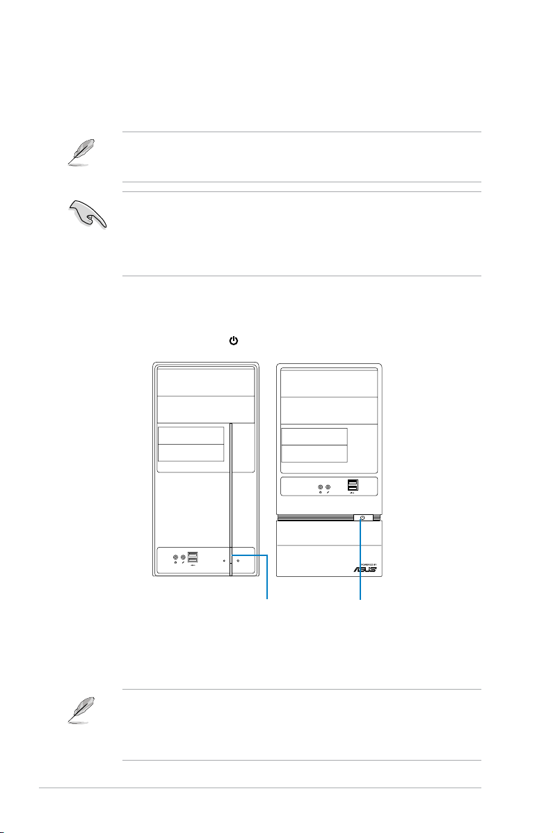
1.2 Front panel
The front panel includes the optical drive bays, power button, and several I/O ports
are located at the front panel.
1.2.1 V2-P5G41Hfrontpanel
3
7
8
6
5
4
1
2
Page 13
1-3ASUS V-series P5G41H
R
1. Two empty 5.25-inch drive bays. These bays are for 5.25-inch IDE/SATA
optical drives.
2. Two empty 3.5-inch drive bays
. These bays are for 3.5-inch hard disk
drives.
3. Power button.
Press this button to turn the system on.
4. Reset button.
Press this button to reboot the system without turning off the
power.
5. HDDLED. This LED lights up when data is read from or written to the hard
disk drive.
6. USB 2.0 ports. These Universal Serial Bus 2.0 (USB 2.0) ports are available
for connecting USB 2.0 devices such as a mouse, printer, scanner, camera,
PDA, and others.
7. Headphone port. This Line In (lime) port connects a headphone with a
stereo mini-plug.
8. Microphone port.
This Mic (pink) port connects a microphone.
1.2.2 V6-P5G41Hfrontpanel
10
11
12
13
14
15
Page 14

1-4 Chapter 1: System introduction
10. Two empty 5.25-inch drive bays. These bays are for 5.25-inch IDE/SATA
optical drives.
11. Two empty 3.5-inch drive bays
. These bays are for 3.5-inch hard disk
drives.
12. Microphone port.
This Mic (pink) port connects a microphone.
13. Headphone port. This Line In (lime) port connects a headphone with a
stereo mini-plug.
14. USB 2.0 ports.
These Universal Serial Bus 2.0 (USB 2.0) ports are available
for connecting USB 2.0 devices such as a mouse, printer, scanner, camera,
PDA, and others.
15. Power button.
Press this button to turn the system on.
This V-series provide V2/V6 two types of front panel for users to choose, please
refer to your product package for the front panel type you purchased.
Page 15
1-5ASUS V-series P5G41H
1.3 Rear panel
The system rear panel includes the power connector and several I/O ports that
allow convenient connection of devices.
1. Voltageselector.
This switch allows you to adjust the system input voltage
according to the voltage supply in your area. See the section “Voltage
selector” on page 1-7 before adjusting this switch.
2. Power connector.
This connector is for the power cable and plug.
3. Power supply unit fan vent.
This vent is for the PSU fan that provides
ventilation inside the power supply unit.
SPDIF OUT
HDMI
DVI
15
16
2
1
7
10
12
6
3
11
17
8
13
20
4
9
14
18
5
19
Do NOT cover the rear vent , and the ambient temperature is limited up to 35
o
C
to prevent the system from overheating.
Page 16
1-6 Chapter 1: System introduction
4. Power Switch. This switch is for switching on/off the power supply unit.
5. Chassis fan vent.
This vent is for the fan that provides ventilation inside the
system chassis.
6. PS/2 mouse port.
This green 6-pin connector is for a PS/2 mouse.
7. PS/2 keyboard port.
This purple 6-pin connector is for a PS/2 keyboard.
8. Optical S/PDIF Out port.
This port connects an external audio output device
via an optical S/PDIF cable.
9. HDMI port.
This port is for a High-Denition Multimedia Interface (HDMI)
connector, and is HDCP compliant allowing playback of HD DVD, Blu-Ray
and other protected content.
10. DVI-DOutport.
This port is for any DVI-D compatible device and is HDCP
compliant allowing playback of HD DVD, Blu-Ray and other protected
content.
11. VideoGraphicsAdapter(VGA)port.
This 15-pin port is for a VGA monitor
or other VGA-compatible devices.
12. USB 2.0 ports 1 ~ 4.
These 4-pin Universal Serial Bus (USB) ports are
available for connecting USB 2.0 devices.
13. LAN(RJ-45)port.
This port allows gigabit connection to a Local Area
Network (LAN) through a network hub. Refer to the table below for the LAN
port LED indications.
Activity/Link SpeedLED
Status Description Status Description
OFF No link OFF 10 Mbps connection
ORANGE Linked ORANGE 100 Mbps connection
BLINKING Data activity GREEN 1 Gbps connection
LANportLEDindications
SPEED
LED
ACT/LINK
LED
LANport
14. RearSpeakerOutport(black).
This port connects the rear speakers in a
4-channel, 6-channel, or 8-channel audio conguration.
15. SideSpeakerOutport(gray).
This port connects the side speakers in an
8-channel audio conguration.
16. Microphoneport(pink).
This port connects a microphone.
17. LineOutport(lime).
This port connects a headphone or a speaker. In
4-channel, 6-channel, and 8-channel conguration, the function of this port
becomes Front Speaker Out.
18. Center/Subwooferport(orange).
This port connects the center/subwoofer
speakers.
Page 17
1-7ASUS V-series P5G41H
Refer to the audio conguration table below for the function of the audio ports in
2, 4, 6, or 8-channel conguration.
Voltageselector
The PSU has a 115 V/230 V voltage selector switch located beside the power
connector. Use this switch to select the appropriate system input voltage according
to the voltage supply in your area.
If the voltage supply in your area is 100-127 V, set this switch to 115 V.
If the voltage supply in your area is 200-240 V, set this switch to 230 V.
Setting the switch to 115V in a 230V environment or 230V in a 115V
environment will seriously damage the system!
115V/230V
Voltageselector
19. LineInport(lightblue).
This port connects the tape, CD, DVD player, or
other audio sources.
Audio2,4,6,or8-channelconguration
Port
Headset
2-channel
4-channel 6-channel 8-channel
Light Blue Line In Line In Line In Line In
Lime Line Out Front Speaker Out Front Speaker Out Front Speaker Out
Pink Mic In Mic In Mic In Mic In
Orange – – Center/Subwoofer Center/Subwoofer
Black – Rear Speaker Out Rear Speaker Out Rear Speaker Out
Gray – – – Side Speaker Out
20. Expansion slot covers.
Remove these covers when installing expansion
cards.
Page 18
1-8 Chapter 1: System introduction
1.4 Internal components
The illustration below is the internal view of the system when you remove the side
cover and the power supply unit. The installed components are labeled for your
reference.
1. Front panel cover
2. 5.25-inch optical drive bays
3. 3.5-inch drive bay
4. Hard disk drive bay
5. Power supply unit
6. CPU socket
7. DIMM sockets
8. ASUS motherboard
9. PCI Express x16 slot
10. PCI Express x1 slot
11. PCI slots
12. Metal bracket lock
P5QPL-VM EPU
1
4
2
3
5
6
7
8
9
10
11
12
Refer to the bundled Quick Installation Guide for installing additional system
components and get assistance from professionals when you disassemble or
assemble the system.
Page 19

1-9ASUS V-series P5G41H
1.5 QualiedVendorsLists(QVL)
DDR2-1066MHz capability
Vendor Part No. Size
SS/DSChip
Brand
Chip NO. CL
DIMM
support
A* B*
A-Data AD21066E002GU 4096MB(2 x 2048MB) DS N/A Heat-Sink Package 5-5-5-15 • •
Apacer 78.0AG9S.9K4 2048MB(2 x 1024MB) DS N/A Heat-Sink Package 5-5-5-15 • •
Apacer 78.AAGAL.9KZ 4096MB(2 x 2048MB) DS N/A Heat-Sink Package 5-5-5-15 • •
Corsair CM2X1024-8500C5 1024MB DS Corsair Heat-Sink Package • •
Corsair CM2X2048-8500C5D 2048MB(2 x 1024MB) DS N/A Heat-Sink Package 5-5-5-15 • •
G.SKILL F2-8500CL5S-1GBPK 1024MB DS N/A Heat-Sink PackageSN:815130037562 5-5-5-15 • •
G.SKILL F2-8500CL5D-2GBPK 2048MB(2 x 1024MB) DS N/A Heat-Sink Package 5-5-5-15 • •
G.SKILL F2-8500CL5D-4GBPI 4096MB(2 x 2048MB) DS N/A Heat-Sink Package 5-5-5-15 • •
G.SKILL F2-8500CL5D-4GBPK 4096MB(2 x 2048MB) DS N/A Heat-Sink Package 5-5-5-15 •
GEIL GB22GB8500C5DC 1024MB SS GEIL GL2L128M88BA25AB 5 • •
GEIL GB24GB8500C5QC 1024MB SS GEIL GL2L128M88BA25AB 5 • •
GEIL GE22GB1066C5DC 1024MB SS GEIL Heat-Sink Package 5 • •
GEIL GE24GB1066C5QC 1024MB SS GEIL Heat-Sink Package 5 • •
GEIL GB24GB8500C5DC 2048MB DS GEIL GL2L128M88BA25AB 5 • •
GEIL GE24GB1066C5DC 2048MB DS GEIL Heat-Sink Package 5 • •
GEIL GX24GB8500C5UDC 4096MB(2 x 2048MB) DS N/A Heat-Sink Package 5 • •
Kingston KHX8500D2K2/1G 1024MB(2 x 512MB) SS N/A Heat-Sink Package 5-5-5-15 • •
Kingston KHX8500D2K2/1GN(EPP) 1024MB(2 x 512MB) SS Kingston Heat-Sink Package 5-5-5-18 • •
Kingston KHX8500D2K2/2GN(EPP) 1024MB DS Kingston Heat-Sink Package 5-5-5-18 • •
Kingston KVR1066D2N7/1G 1024MB DS Elpida E5108AJBG-1J-E 7 • •
Kingston KHX8500D2K2/2G 2048MB(2 x 1024MB) DS N/A Heat-Sink Package 5-5-5-15 • •
Kingston KHX8500D2K2/4G 2048MB(2 x 1024MB) DS N/A Heat-Sink Package 5-5-5-15 • •
OCZ OCZ2N10662GK 2048MB(2 x 1024MB) DS N/A Heat-Sink Package 5-5-5-15 •
OCZ OCZ2N1066SR2DK(Epp) 2048MB(2 x 1024MB) DS OCZ
Heat-Sink Package
004820806001601-2
5-5-5-15 • •
OCZ OCZ2N1066SR2GK(EPP) 2048MB(2 x 1024MB) DS N/A Heat-Sink Package 5 •
OCZ OCZ2RPR10664GK 4096MB(2 x 2048MB) DS N/A Heat-Sink Package 5-5-5-15 • •
PSC AL8E8G73F-AE1 2048MB DS PSC
A3R1GE3FGF907MAT0FTAIWANG8E
5-5-5-12 • •
Qimonda HYS64T128000EU-1.9-C2 1024MB DS Qimonda HYB18T1G800C2F-1.9FSS25253 • •
Transcend TX1066QLU-2GK 2048MB(2 x 1024MB) SS N/A Heat-Sink Package 5 • •
Transcend TX1066QLJ-2GK 2048MB(2 x 1024MB) DS Transcend Heat-Sink Package 5 •
Transcend TX1066QLU-4GK 4096MB(2 x 2048MB) DS Transcend Heat-Sink Package 5 • •
AENEON AXT860UD20-19E 4096MB(2 x 2048MB) DS AENEON Heat-Sink Package 6 • •
Elixir M2Y1G64TU88D5B-BD 1024MB SS Elixir M2TU1G800E-BD 5 • •
Mushkin 996612 2048MB(2 x 1024MB) DS N/A Heat-Sink Package 5-5-5-15 • •
Mushkin 996619 4096MB(2 x 2048MB) DS N/A Heat-Sink Package 5-5-5-15 • •
Page 20

1-10 Chapter 1: System introduction
Vendor Part No. Size
SS/DSChip
Brand
Chip NO. CL
DIMM
support
A* B*
A-Data M2GVD6G3H3160Q1E52 512MB SS VDATA VD29608A8A-25EG20813 • •
A-Data AD2800E001GOU 2048MB(2 x 1024MB) SS N/A Heat-Sink Package 4-4-4-12 • •
A-Data M2GVD6G314170Q1E58 1024MB DS VDATA VD29608A8A-25EG80813 • •
A-Data AD2800E002GOU 4096MB(2 x 2048MB) DS N/A Heat-Sink Package 4-4-4-12 • •
Apacer 78.91G91.9K5 512MB SS Apacer AM4B5708JQJS8E0751C 5 • •
Apacer 78.01GA0.9K5 1024MB SS Apacer AM4B5808CQJS8E0749D 5 • •
Apacer 78.A1GA0.9K4 2048MB DS Apacer AM4B5808CQJS8E0740E 5 • •
Apacer 78.A1GA0.9K4 2048MB DS Apacer AM4B5808CQJS8E0747D 5 • •
Corsair CM2X1024-6400 1024MB DS Corsair Heat-Sink Package • •
Corsair XMS2-6400 1024MB DS Corsair Heat-Sink Package 4 • •
Corsair XMS2-6400 1024MB DS Corsair Heat-Sink Package 5 • •
Corsair CM2X2048-6400C5DHX 4096MB(2 x 2048MB) DS N/A Heat-Sink Package 5 • •
Corsair CM2X2048-6400C5 4096MB(2 x 2048MB) DS N/A Heat-Sink Package 5 • •
Crucial BL12864AL80A.8FE5(EPP) 2048MB(2 x 1024MB) SS N/A Heat-Sink Package 4-4-4-12 • •
Crucial BL25664AL80A.16FE5(EPP) 4096MB(2 x 2048MB) DS N/A Heat-Sink Package 4-4-4-12 • •
Crucial BL25664AR80A.16FE5(EPP) 4096MB(2 x 2048MB) DS N/A Heat-Sink Package 4-4-4-12 • •
G.SKILL F2-6400CL5D-1GBNQ 512MB SS G.SKILL Heat-Sink Package SN:8151030036642 5-5-5-15 • •
G.SKILL F2-6400CL4D-2GBPK 1024MB DS G.SKILL Heat-Sink Package 4 • •
G.SKILL F2-6400CL5D-2GBNQ 1024MB DS G.SKILL Heat-Sink Package 5 • •
G.SKILL F2-6400CL4D-4GBPK 2048MB DS G.SKILL Heat-Sink Package 4 • •
G.SKILL F2-6400CL5D-4GBPQ 2048MB DS G.SKILL Heat-Sink Package 5 • •
G.SKILL F2-6400CL6Q-16GMQ 4096MB DS N/A Heat-Sink Package 5 • •
GEIL GB22GB6400C4DC 1024MB DS GEIL GL2L64M088BA30EB 5 • •
GEIL GB22GB6400C5DC 1024MB DS GEIL GL2L64M088BA30EB 5 • •
GEIL GB24GB6400C4QC 1024MB DS GEIL GL2L64M088BA30EB 4 • •
GEIL GB24GB6400C5QC 1024MB DS GEIL GL2L64M088BA30EB 5 • •
GEIL GE22GB800C4DC 1024MB DS GEIL Heat-Sink Package 4 • •
GEIL GE22GB800C5DC 1024MB DS GEIL Heat-Sink Package 5 • •
GEIL GE24GB800C4QC 1024MB DS GEIL Heat-Sink Package 4 • •
GEIL GE24GB800C5QC 1024MB DS GEIL Heat-Sink Package 5 • •
GEIL GX22GB6400DC 1024MB DS GEIL Heat-Sink Package 5 • •
GEIL GX22GB6400UDC 1024MB DS GEIL Heat-Sink Package 4 • •
GEIL GB24GB6400C4DC 2048MB DS GEIL GL2L128M88BA25AB 4 • •
GEIL GB24GB6400C5DC 2048MB DS GEIL GL2L128M88BA25AB 5 • •
GEIL GB28GB6400C4QC 2048MB DS GEIL GL2L128M88BA25AB 4 • •
GEIL GB28GB6400C5QC 2048MB DS GEIL GL2L128M88BA25AB 5 • •
GEIL GE24GB800C4DC 2048MB DS GEIL Heat-Sink Package 4 • •
GEIL GE24GB800C5DC 2048MB DS GEIL Heat-Sink Package 5 • •
GEIL GE28GB800C4QC 2048MB DS GEIL Heat-Sink Package 4 • •
GEIL GE28GB800C5QC 2048MB DS GEIL Heat-Sink Package 5 • •
GEIL GX22GB6400CUSC 2048MB DS GEIL Heat-Sink Package 4 • •
GEIL GX22GB6400LX 2048MB DS GEIL Heat-Sink Package 5 • •
GEIL GX24GB6400DC 2048MB DS GEIL Heat-Sink Package 5 • •
Kingmax KLDC28F-A8KI5 512MB SS Kingmax KKA8FF1XF-JFS-25A • •
Kingmax KKB8FFBXF-CFA-25U 1024MB SS Kingmax KLDD48F-B8KB5 • •
kingmax KLDE88F-B8KB5 2048MB DS kingmax KKB8FFBXF-CFA-25U • •
Kingston KVR800D2N6/ 512 512MB SS Elpida E5108AJBG-8E-E 6 • •
Kingston KHX6400D2LLK2/1GN 1024MB(2 x 512MB) SS Kingston Heat-Sink Package 4-4-4-12 • •
Kingston KVR800D2N5/1G(Low Prole) 1024MB SS Kingston D1288TEFCGL25U 5 • •
Kingston KHX6400D2LL/1G 1024MB DS Kingston Heat-Sink Package 4-4-4-12 • •
DDR2-800MHz capability
continued on the next page
Page 21

1-11ASUS V-series P5G41H
Vendor Part No. Size
SS/
DS
Chip Brand Chip NO. CL
DIMM
support
A* B*
Kingston KVR800D2N5/1G 1024MB DS Kingston
D6408TR4CGL25USL36240
6PECXA
5 • •
Kingston KVR800D2N6/1G(Low Prole) 1024MB DS Elpida E510BAJBG-8E-E 6 • •
Kingston KVR800D2N6/1G 1024MB DS Elpida E5108AJBG-8E-E 6 • •
Kingston KHX6400D2K2/2G
2048MB
(2 x 1024MB)
DS N/A Heat-Sink Package 5-5-5-15 • •
Kingston KHX6400D2/2G 2048MB DS Kingston Heat-Sink Package 5 • •
Kingston KVR800D2N5/2G(Low Prole) 2048MB DS Kingston D1288TPFCGL25U 5 • •
Kingston KVR800D2N5/2G 2048MB DS Elpida E1108ACBG-8E-E 5 • •
Kingston KVR800D2N6/2G(Low Prole) 2048MB DS Elpida E8105ACBG-8E-E 6 • •
Kingston KVR800D2N6/2G 2048MB DS Qimonda HYB18T1G800C2F-2.5 6 • •
Kingston KVR800D2N6/4G 4096MB DS Elpida E2108ABSE-8G-E 6 • •
OCZ OCZ2G800R22GK 1024MB DS OCZ Heat-Sink Package 4-5-5-15 • •
OCZ OCZ2P800R22GK 1024MB DS OCZ Heat-Sink Package 4-4-4-15 • •
OCZ OCZ2RPR8002GK 1024MB DS OCZ Heat-Sink Package 4-4-4-15 • •
OCZ OCZ2VU8004GK 1024MB DS OCZ Heat-Sink Package 5-6-6-18 • •
OCZ OCZ2SE8002GK
2048MB
(2 x 1024MB)
DS N/A Heat-Sink Package 5-5-5-15 • •
OCZ OCZ2F8004GK(EPP) 2048MB DS N/A Heat-Sink Package 5-4-4-18 • •
PSC AL7E8F73C-8E1 1024MB SS PSC A3R1GE3CFF734MAA0E 5 • •
PSC AL8E8F73C-8E1 2048MB DS PSC A3R1GE3CFF734MAA0E 5 • •
PSC PL8E8F73C-8E1 2048MB DS PSC SHG772-AA3G 5 • •
PSC PL8E8G73E-8E1 2048MB DS PSC XCP271A3G-A 5 • •
Qimonda HYS64T256020EU-2.5-C2 2048MB DS Qimonda HY818T1G800C2F-2.5 5 • •
Samsung K4T51083QG-HCF7 512MB SS Qimonda M378T6553GZS-CF7 6 • •
Samsung K4T1G084QQ-HCF7 1024MB SS Qimonda M378T2863QZS-CF7 6 • •
Samsung K4T51083QG-HCF7 1024MB DS Samsung M378T2953GZ3-CF7 6 • •
Samsung K4T1G084QQ-HCF7 2048MB DS Samsung M37875663QZ3-CF7 6 • •
Samsung M378T5263AZ3-CF7 4096MB DS Samsung K4T2G084QA-HCF7 • •
Super Talent T800UB1GC4 1024MB DS Super Talent Heat-Sink Package 4 • •
Transcend TS64MLQ64V8J 512MB SS Micron 7HD22 D9GMH 5 • •
Transcend JM800QLU-1G 1024MB SS Transced TQ1243PCF8 5 • •
Transcend TS128MLQ64V8U 1024MB SS ELPIDA E1108ACBG-8E-E 5 • •
Transcend JM800QLJ-1G 1024MB DS Transced TQ123PJF8F0801 5 • •
Transcend JM800QLJ-1G 1024MB DS Transcend TQ123YBF8 T0747 5 • •
Transcend TS128MLQ64V8J 1024MB DS Mircon 7HD22D9GMH 5 • •
Transcend JM800QLU-2G 2048MB DS Transced TQ243PCF8 5 • •
Transcend TS256MLQ64V8U 2048MB DS Elpida E1108ACBG-8E-E 5 • •
AENEON AET760UD00-25DC08X 1024MB SS AENEON AET03R250C 0732 5 • •
AENEON AET860UD00-25DC08X 2048MB DS AENEON AET03R25DC 0732 5 • •
ASINT SLY2128M8-JGE 1024MB SS ASINT DDRII1208-GE 8115 • •
ASINT SLZ2128M8-JGE 2048MB DS ASINT DDRII1208-GE 8115 • •
Elixir M2Y1G64TU88D5B-AC 0828.GS 1024MB SS Elixir N2TU16800E-AC • •
ELIXIR M2Y1G64TU8HB0B-25C 1024MB DS ELIXIR N2TU 51280BE-25C802006Z1DV 5 •
Elixir M2Y2G64TU8HD5B-AC 0826.SG 2048MB DS Elixir N2TUG80DE-AC • •
MDT MDT 512MB 512MB SS MDT 18D 51280D-2.50726F 5 •
MDT MDT 1024MB 1024MB DS MDT 18D 51280D-2.50726E 5 • •
TAKEMS TMS51B264C081-805EP 512MB SS takeMS MS18T 51280-2.5P0710 5 • •
TAKEMS TMS1GB264C081-805EP 1024MB DS takeMS MS18T 51280-2.5P0716 5 • •
UMAX D48001GP3-63BJU 1024MB DS UMAX U2S12D30TP-8E • •
UMAX D48002GP0-73BCU 2048MB DS UMAX U2S24D30TP-8E 5 • •
DDR2-800MHz capability
Page 22

1-12 Chapter 1: System introduction
DDR2-667MHz capability
Vendor Part No. Size
SS/
DS
Chip Brand Chip NO. CL
DIMM
support
A* B*
A-Data M2OAD5H3J4170I1C53 2048MB DS ADATA AD20908A8A-3EG 30724 • •
Apacer 78.91G92.9K5 512MB SS Apacer AM4B5708JQJS7E0751C 5 • •
Apacer AU 512E667C5KBGC 512MB SS Apacer AM4B5708GQJS7E06332F 5 • •
Apacer AU 512E667C5KBGC 512MB SS Apacer AM4B5708MIJS7E0627B 5 • •
Apacer 78.01G9O.9K5 1024MB SS Apacer AM4B5808CQJS7E0751C 5 • •
Apacer AU01GE667C5KBGC 1024MB DS Apacer AM4B5708GQJS7E0636B • •
Apacer AU01GE667C5KBGC 1024MB DS Apacer AM4B5708MIJS7E0627B 5 • •
Apacer AM4B5808CQJS7E0749B 2048MB DS Apacer 78.A1G9O.9K4 5 • •
Corsair VS 512MB667D2 512MB DS Corsair MIII0052532M8CEC • •
Corsair VS1GB667D2 1024MB DS Corsair MID095D62864M8CEC • •
Corsair XMS2-5400 1024MB DS Corsair Heat-Sink Package 4 • •
G.SKILL F2-5400PHU2-2GBNT
2048MB
(2 x 1024MB)
DS G.SKILL D2 64M8CCF 0815 C7173S 5-5-5-15 • •
G.SKILL F2-5300CL5D-4GBMQ
4096MB
(2 x 2048MB)
DS G.SKILL
Heat-Sink Package
SN:8151030036559
5-5-5-15 • •
GEIL GX21GB5300SX 1024MB DS GEIL Heat-Sink Package 3 • •
GEIL GX22GB5300LX 2048MB DS GEIL Heat-Sink Package 5 • •
GEIL GX24GB5300LDC 2048MB DS GEIL Heat-Sink Package 5 • •
Kingmax KLCC28F-A8KB5 512MB SS Kingmax KKEA88B4LAUG-29DX • •
Kingmax KLCD48F-A8KB5 1024MB DS Kingmax KKEA88B4LAUG-29DX • •
Kingston KVR667D2N5/ 512(Low Prole) 512MB SS Kingston D6408TR7CGL25U 5 • •
Kingston KVR667D2N5/ 512 512MB SS Kingston
SO1237650821 SBP D6408TR4CGL25
USL074905PECNB
5 • •
Kingston KVR667D2N5/1G(Low Prole) 1024MB DS PSC E5108AJBG-8E-E 5 • •
Kingston KVR667D2N5/2G(Low Prole) 2048MB DS Elpida E1108ACBG-8E-E 5 • •
Kingston KVR667D2N5/2G 2048MB DS Micron 7RE22 D9HNL 5-5-5-15 • •
Micron MT8HTF12864AY-667E1 1024MB SS Micron D9HNL 7ZE17 5 • •
PSC AL6E8E63J-6E1 512MB SS PSC A3R12E3JFF717B9A00 5 • •
PSC AL7E8F73C-6E1 1024MB SS PSC A3R1GE3CFF734MAA0J 5 • •
PSC AL6E8E63J-6E1 1024MB DS PSC A3R12E3JFF717B9A01 5 • •
PSC AL8E8F73C-6E1 2048MB DS PSC A3R1GE3CFF733MAA00 5 • •
Samsung M378T5263AZ3-CE6 4096MB DS Samsung K4T2G084QA-HCE6 • •
Super
Talent
T667UB1GV 1024MB DS Super Talent PG 64M8-800 0750 5 • •
Transcend JM667QLU-1G 1024MB SS Transced TQ243PCF8T0838 5 • •
Transcend JM667QLJ-1G 1024MB DS Elpida E5108AJBG-6E-E 5 • •
Transcend JM667QLU-2G 2048MB DS Transced TQ243PCF8T0834 5 • •
Twinmos 8D-A3JK5MPETP 512MB SS PSC A3R12E3GEF633ACAOY 5 • •
AENEON AET860UD00-30DB08X 2048MB DS AENEON AET03F30DB 0730 5 • •
Asint SLX264M8-J6E 512MB SS Asint DDRII6408-6E • •
ASINT SLY2128M8-J6E 1024MB SS ASINT DDRII1208-6E 8115 • •
Century CENTURY 512MB 512MB SS Hynix HY5PS12821AFP-Y5 • •
Century CENTURY 512MB 512MB SS Nanya NT5TU64M8AE-3C • •
Century CENTURY 1G 1024MB DS Nanya NT5TU64M8AE-3C • •
ELIXIR M2Y1G64TU8HA2B-3C 1024MB DS elixir M2TU 51280AE-3C717095R28F 5 • •
Elixir M2Y1G64TU8HBOB-3C 1024MB DS Elixir N2TU 51280BE-3C639009W1CF 5 • •
KINGBOX 512MB 667MHz 512MB SS KINGBOX EPD264082200-4 •
KINGBOX DDRII 1G 667MHz 1024MB DS KINGBOX EPD264082200-4 •
continued on the next page
Page 23
1-13ASUS V-series P5G41H
DDR2 667MHz capability
SS - Single-sided / DS - Double-sided
DIMM support:
• A*: Supports one module inserted in any slot as Single-channel
memory conguration.
• B*: Supports one pair of modules inserted into both the yellow slots
as one pair of Dual-channel memory conguration.
Visit the ASUS website at www.asus.com for the latest QVLs.
Vendor Part No. Size
SS/
DS
Chip Brand Chip NO. CL
DIMM
support
A* B*
Leadmax LRMP 512U64A8-Y5 1024MB DS Hynix HY5PS12821CFP-Y5 C 702AA 5 • •
MDT DDRII 512 PC667 512MB DS MDT 18D 51201D-30726E 4 • •
MDT MDT 1024MB 1024MB DS MDT 18D 51280D-30646E 4 • •
TAKEMS TMS51B264C081-665AP 512MB SS takeMS MS18T 51280-3S0627D 5 • •
TAKEMS TMS51B264C081-665QI 512MB SS takeMS MS18T 51280-3 5 • •
TAKEMS TMS1GB264C081-665AE 1024MB DS takeMS MS18T 51280-3SEA07100 5 • •
TAKEMS TMS1GB264C081-665AP 1024MB DS takeMS MS18T 51280-3SP0717A 5 •
TAKEMS TMS1GB264C081-665QI 1024MB DS takeMS MS18T 51280-3 5 • •
TEAM TVDD1.02M667C4 1024MB DS TEAM T2D648PT-6 • •
UMAX D46701GP3-63BJU 1024MB DS UMAX U2S12D30YP-6E • •
UMAX D46702GP0-73BCU 2048MB DS UMAX U2S24D30TP-6E 5 • •
Page 24

1-14 Chapter 1: System introduction
Page 25

R
R
This chapter helps you power up the
system and install drivers and utilities
from the support DVD.
Chapter 2
Starting up
Page 26
2-2 Chapter 2: Starting up
2.1 Installing an operating system
The barebone system supports Windows® XP/Vista operating systems (OS).
Always install the latest OS version and corresponding updates so you can
maximize the features of your hardware.
2.3 Support DVD information
The support DVD that came with the system contains useful software and several
utility drivers that enhance the system features.
2.2 Powering up
Press the system power button ( ) to enter the OS.
Motherboard settings and hardware options vary. Use the setup procedures
presented in this chapter for general reference only. Refer to your OS
documentation for more information.
•
Screen display and driver options may not be the same for different
operating system versions.
•
The contents of the support DVD are subject to change at any time without
notice. Visit the ASUS website at www.asus.com for updates.
• Windows XP OS setup cannot recognize Serial ATA hard drives in a RAID
set without the necessary drivers. Use a RAID driver disk when installing
Windows XP OS to a Serial ATA hard drive included in a RAID set.
• From the Windows XP setup screen, press F6 when prompted then follow
succeeding screen instructions to install the SATA drivers.
R
Press to turn ON the system
Page 27
2-3ASUS V-series P5G41H
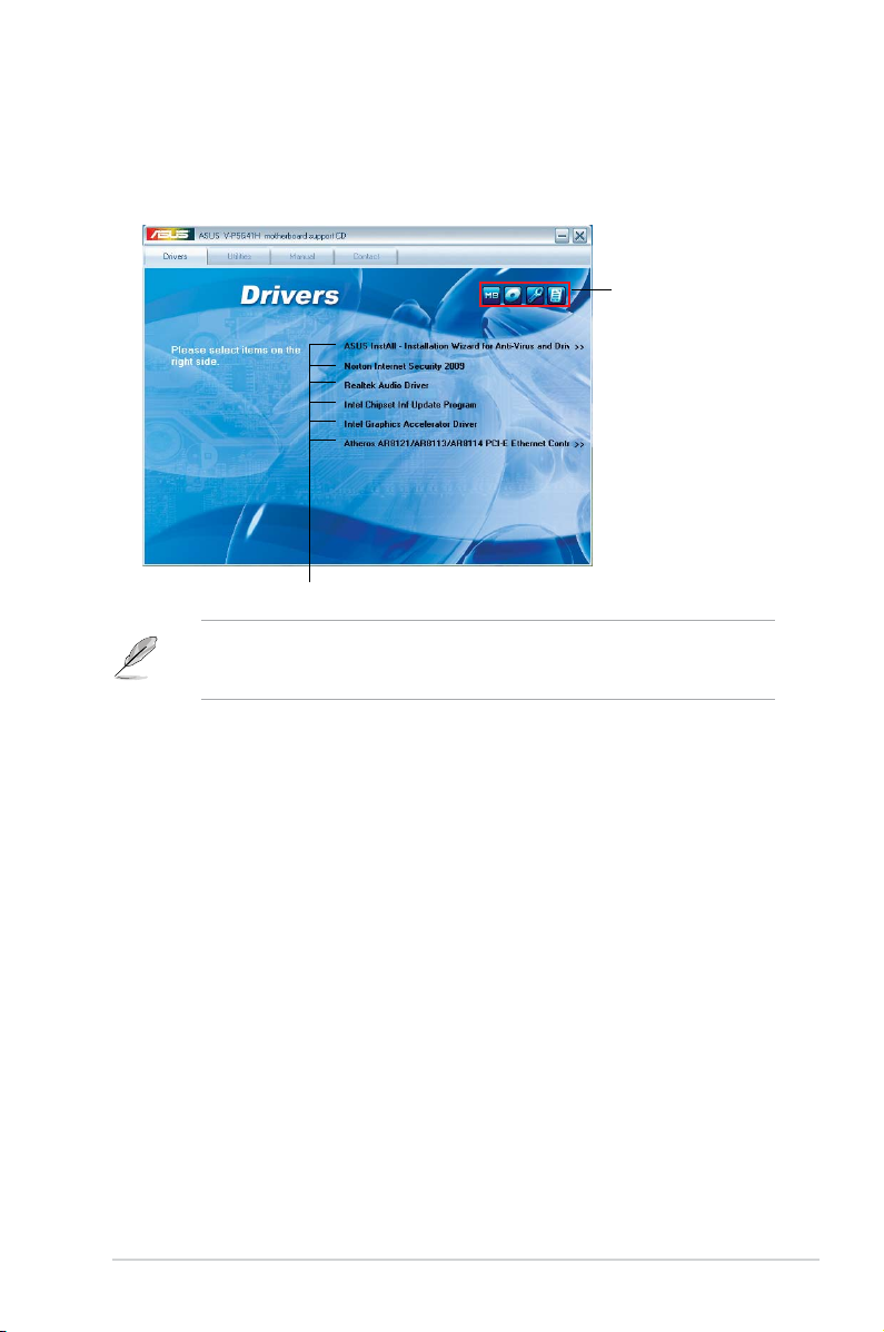
2.3.1 RunningthesupportDVD
To begin using the support DVD, place the DVD in your optical drive. The DVD
automatically displays the Drivers menu if Autorun is enabled in your computer.
If Autorun is NOT enabled in your computer, browse the contents of the support
DVD to locate the le ASSETUP.EXE from the BIN folder. Double-click the
ASSETUP.EXE to run the DVD.
Click an item to install
Click an icon to
display support
DVD/motherboard
information
ASUSInstAll-InstallationWizardforAnti-VirusandDriversUtility
Launches the ASUS InstAll driver installation wizard.
Norton Internet Security 2009
Installs the Norton Internet Security 2009.
Reaktek Audio Driver
Installs the Realtek audio driver and application.
Intel Chipset Inf Update Program
Installs the Intel® chipset Inf update program.
Intel Graphics Accelerator Driver
Installs the Intel® Graphics accerlerator driver.
Atheros AR8121/AR8113/AR8114 PCI-E Ethernet Controller
Installs the Atheros® AR8121/AR8113/AR8114 PCI-E Ethernet Controller.
Page 28
2-4 Chapter 2: Starting up
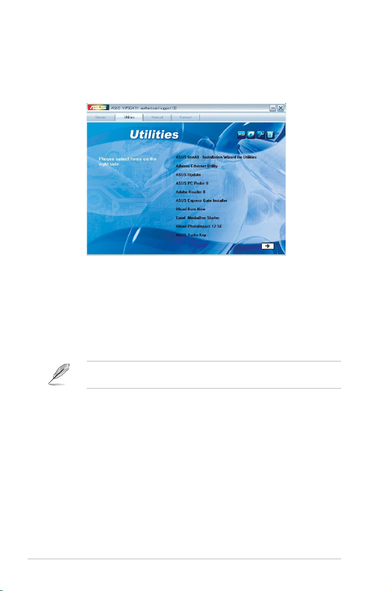
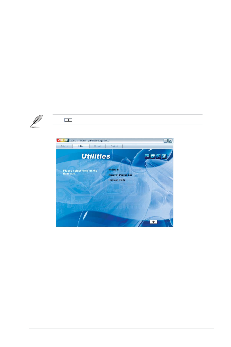
2.3.2 Utilities menu
The Utilities menu shows the applications and other software that the motherboard
supports.
ASUS InstAll-Installation Wizard for Utilities
Installs all of the utilities through the Installation Wizard.
Atheros Ethernet Utility
Installs the Atheros® Ethernet Utility.
ASUS Update
Allows you to download the latest version of the BIOS from the ASUS website.
Before using the ASUS Update, make sure that you have an Internet connection
so you can connect to the ASUS website.
ASUS PC Probe II
This smart utility monitors the fan speed, CPU temperature, and system voltages,
and alerts you of any detected problems. This utility helps you keep your computer
in healthy operating condition.
Adobe Acrobat Reader 8
Installs the Adobe® Acrobat® Reader that allows you to open, view, and print
documents in Portable Document Format (PDF).
ASUS Express Gate Installer
Installs the ASUS Express Gate application.
Page 29
2-5ASUS V-series P5G41H
Ulead Burn. Now
Installs the Ulead Burn. Now application for Audio DVD,CD and data disc creation.
Corel MediaOne Starter
Installs the Corel MediaOne Starter application to easily manage, edit share and
protect your multimedia data.
Ulead Photolmpact 12 SE
Installs the Photolmpact image editing software.
ASUSTurboKey
Installs ASUS Turbo Key.
Click to display the next screen.
WinZip 11
Installs the Winzip utility for easy le-compression and protection.
Microsoft DirectX 9.0c
Installs the Microsoft® DirectX 9.0c driver. The Microsoft DirectX® 9.0c is a
multimedia technology that enhances computer graphics and sound. DirectX®
improves the multimedia features of you computer so you can enjoy watching
TV and movies, capturing videos, or playing games in your computer. Visit the
Microsoft website (www.microsoft.com) for updates.
FarStone Utility
Installs the FarStone Utility.
Page 30

2-6 Chapter 2: Starting up
2.3.3 Manual menu
The Manual menu contains a list of supplementary user manuals. Click an item to
open the folder of the user manual.
Most user manual les are in Portable Document Format (PDF). Install the
Adobe® Reader from the Utilities menu before opening a user manual le.
RealtekHDAudioUser’sManual
Allows you to open the Realtek HD Audio User’s Manual.
ASUS Motherboard Installation Guide
Allows you to open the ASUS Motherboard Installation Guide.
NIS 2009 Subscription Renewal Guide
Allows you to open the NIS 2009 Subscription Renewal Guide.
Page 31

2-7ASUS V-series P5G41H
2.3.4 ASUS Contact information
Click the Contact tab to display the ASUS contact information. You can also nd
this information on the inside front cover of this user guide.
Page 32

2-8 Chapter 2: Starting up
2.3.5 Other information
The icons on the top right corner of the screen give additional information on the
motherboard and the contents of the support DVD. Click an icon to display the
specied information.
Motherboard Info
Displays the general specications of the motherboard.
BrowsethisDVD
Displays the support DVD contents in graphical format.
P5QPL-VM EPU
03/14/2009
0206
American Megatrends Inc.
Rav 1.xx
P5QPL-VM EPU V-P5G41H
ASUSTeK Computer INC.
P5QPLVME.ROM
V-P5G41H
Page 33

2-9ASUS V-series P5G41H
Technical support Form
Displays the ASUS Technical Support Request Form that you have to ll out when
requesting technical support.
Filelist
Displays the contents of the support DVD and a brief description of each in text
format.
Page 34

2-10 Chapter 2: Starting up
Installing AI Manager
To install AI Manager on your computer:
1. Place the support CD in the optical drive. If Autorun is enabled, the Drivers
installation wizard appears.
If Autorun is not enabled in your computer, locate the setup.exe le from the
ASUS AI Manager folder in the support CD. Double-click the setup.exe le to
start installation.
2. Click the Utilities tab, then click ASUS AI Manager.
3. Follow the screen instructions to complete the installation.
LaunchingAIManager
To launch the AI Manager from the Windows® desktop, click Start > All Programs
> ASUS > AI Manager 1.xx.xx > AI Manager. The AI Manager quick bar appears
on the desktop.
After launching the application, the AI Manager icon
appears in the Windows® taskbar.
Right-click this icon to switch between quick
bar and main window, and to launch the
AI Manager either from the quick bar or
taskbar.
2.4 Software information
Most of the applications in the support DVD have wizards that will conveniently
guide you through the installation. View the online help or readme le that came
with the software for more information.
2.4.1 ASUS AI Manager
ASUS AI Manager is a utility which gives you quick and easy access to frequentlyused applications.
Page 35

2-11ASUS V-series P5G41H
AI Manager quick bar
The AI Manager quick bar saves the desktop space and allows you to launch
the ASUS utilities or display system information easily. Click any of the Main, My
Favorites, Support or Information tab to display the menu’s contents.
Main
My Favorites
Support
Information
Close button
Maximize / restore button
Minimize button
Click the Maximize/restore button to switch between full window and quick
bar. Click the Minimize button to keep the AI Manager on the taskbar. Click the
Close button to quit the AI Manager.
Main
The Main menu contains ve utilities: AI Disk, AI Security, AI Boosting, AI Gear,
and AI Probe. Click the arrow on the Main menu icon to browse through the
utilities in the main menu.
AI Disk
AI Disk allows you to easily clear temporary IE les, IE cookies, IE URLs, IE
history, or the Recycle Bin. Click the AI Disk icon on the quick bar to display
the full AI Disk window and select the items you want to clear. Click Apply
when done.
Click to extend or restore
Click to display
items on the right
Click to display
items on the left
Page 36

2-12 Chapter 2: Starting up
AI Security
AI Security enables you to set a password to secure your devices, such as
USB ash disks and CD/DVD disks, from unauthorized access.
To lock a device:
1. When using AI Security for the rst time, you are asked to set a
password. Enter a password with at most 20 alphanumeric characters.
2. Conrm the password.
3. Key in the password hint (recommended).
4. When done, click
Ok.
5. Select the device you want to lock, then click
Apply.
6. Key in the password you have set previously, then click
Ok. The selected
device is locked and not accessible.
To unlock the selected device:
1. Uncheck the checkbox of the selected device, then click
Apply.
2. Key in the password you have set previously, then click
Ok. The selected
device is unlocked.
To change password:
Click Change Password
, then follow the on-screen instructions to change
password.
Page 37

2-13ASUS V-series P5G41H
AI Booting
AI Booting allows you to specify the boot device priority sequence.
To specify the boot sequence:
1. Select a device, then click on the left/right button to specify the boot
sequence.
2. When done, press Apply.
AI Gear
AI Gear provides four system performance modes that allows you to select
the best settings for your computing needs. This utility adjusts the processor
frequency and voltage to minimize system noise and power consumption.
Select your preferred mode, then click Yes to conrm your selection.
Page 38

2-14 Chapter 2: Starting up
AI Probe
AI Probe automatically detects and displays the motherboard and CPU
temperatures, CPU fan speed, and the voltage output. You can adjust the
values as you need.
Click the Temperature, Voltage, or Fan Speed tab, then select an item to
enable and change the value by dragging the bar.
My Favorites
My Favorites allows you to add applications that you frequently use, saving you
from searching for the applications throughout your computer.
To add an application:
1. Click
Add, then locate the application you want to add to My Favorites.
2. Click
Open on the le location window. The application is added to My
Favorites list.
Right click on the application icon to launch, delete, or rename the selected
application. You can also double click to launch the selected application.
Page 39

2-15ASUS V-series P5G41H
Support
Click any links on the Support window to go to the ASUS website, technical
support website, download support website, or contact information.
Information
Click the tab on the Information window to see the detailed information about your
system, motherboard, CPU, BIOS, installed device(s), and memory.
Page 40

2-16 Chapter 2: Starting up
2.4.2 ASUS Express Gate
ASUS Express Gate is an instant-on environment that gives you quick access to
the Internet. Within a few seconds of powering on your computer, you will be at the
Express Gate menu where you can start the web browser, Skype, or other Express
Gate softwares.
Installing ASUS Express Gate
• ASUS Express Gate supports installation on SATA HDDs in IDE mode only.
• ASUS Express Gate supports HDDs connected to motherboard chipset-
controlled onboard SATA ports
only. All onboard extended SATA ports and
external SATA ports are NOT supported.
• ASUS Express Gate supports installation on USB HDDs and Flash drives,
but the software performance may be slower than installed on SATA HDDs.
To install Express Gate on your computer
1. Place the support CD/DVD to the optical drive. The
Drivers installation tab
appears if your computer has enabled Autorun feature.
2. Click the
Utilities tab, then click ASUS Express Gate Installer.
3. Select the language for installation and click
OK.
4. The InstallShield Wizard for
Express Gate appears. Click Next
to continue.
Page 41

2-17ASUS V-series P5G41H
The First Screen
Express Gate’s rst screen appears within
a few seconds after you power on the
computer. From here, you can immediately
start the web browser or Skype.
You can also choose to continue booting
normally (e.g. to your installed OS such
as Windows), enter BIOS setup, or power
off.
If you don’t make any selection, Express
Gate will automatically exit and boot to your
normal OS after a certain amount of time. The timer countdown is shown on-screen
inside the “boot to OS” button. As you move the mouse or type a key, the countdown
stops and the timer disappears, so you can take your time to make a selection.
The Express Gate Environment
The very rst time you enter the Express
Gate environment (by launching either web
or Skype from the rst screen), a rst time
wizard will guide you through basic Express
Gate congurations. Basic congurations
include language, date and time and screen
resolution.
5. Select the target disk volume for you
to install Express Gate. If you have
multiple volumes and OS installed in
your hard drive, it is recommended
to install Express Gate in VolumeC.
Click Next to continue.
6. Follow the screen instructions to
complete installation.
Page 42

2-18 Chapter 2: Starting up
KnowingtheExpressGatehot-keys
Here is a list of common-used hot-keys for Express Gate.
In the First Screen:
Key Function
PAUSE/BREAK Power-off
ESC Continue to boot OS
DEL Enter BIOS setup
F8 Enter Boot selection pop-up
In the Express Gate Environment:
Key Function
<Alt> + <Tab> Switch between softwares
<Ctrl> + <Alt> + <Del> Bring up Power-Off dialog box
<Ctrl> + <Alt> + <Print Screen> Save screen snapshot as picture to le
Once inside the Express Gate environment, click on the icons on the LaunchBar,
by default at bottom of the screen, to launch or switch between softwares. You can
re-arrange, re-size and move windows. Bring a window to the foreground by clicking
within it or by clicking on its corresponding software icon. Re-size a window by dragging
any of its four corners. Move a window by dragging its title bar.
Besides using the LaunchBar, you can also switch between softwares by pressing
<Alt> +<Tab> on the keyboard. You can also right-click anywhere on the desktop to
bring up a menu of softwares.
The red triangle on an software icon in the LaunchBar denotes that the software is
already running. This means that you can switch to it without any delay. In the rare
case where an software stops responding, right-click on its icon to force close it.
Page 43

2-19ASUS V-series P5G41H
UsingtheCongurationPanel
Use the conguration panel to change various Express Gate settings.
• Screen Settings: Choose the most optimal screen resolution for your display.
• VolumeControl
: Control the volume for your speaker output, microphone
input, etc.
The rst-time Wizard will run again when you enter the Express Gate
environment after clearing its settings.
Click on an icon to open a particular conguration tool. The following tools are
available:
• Date and Time
: set current date and time as well as time zone.
• Input Method
: choose your preferred input language and method.
• LanguageandKeyboard
: choose your language and keyboard preferences.
• LaunchBarSettings
: customize your LaunchBar (where it docks, whether it
auto-hides, etc.)
•
Network: Specify how your computer connects to the Internet. Enable the
network port. LAN1 refers to the RJ-45 network port on your computer. Also
specify whether to use DHCP (most common) or static IP. For PPPoE and
wireless (optional), set the login credentials (user name, password, SSID, etc.)
as well.
• Environment Settings
: This function allows you to clear the Express Gate
settings, as well as any personal information stored by the web browser
(Bookmarks, Cookies, History, etc.). The user data will be reset to the original
default conguration.
After you click Restore System
, a conrmation dialog box will open. If you
click “Yes” in the conrmation dialog box, your system will immediately restart
and then re-enter Express Gate to nish clearing the settings. This is also
useful in the rare case where settings might become corrupted.
Page 44
2-20 Chapter 2: Starting up
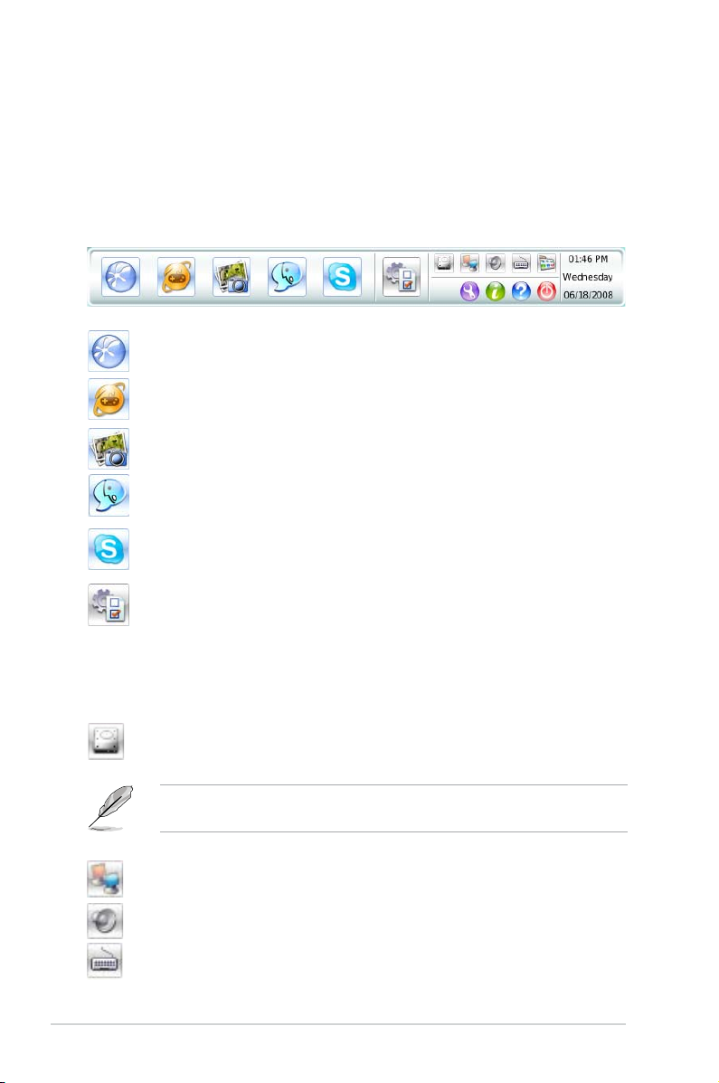
UsingtheLaunchBar
The LaunchBar has several system icons that show you various system statuses and
let you congure individual Express Gate settings. The LaunchBar can be congured
to auto-hide, if you want more screen space for the softwares. It can also be congured
to dock on any of the four sides of the screen.
ASUS Express Gate supports le uploading from SATA HDDs, ODDs and USB
drive and downloading to USB drives only.
Starts the
Web Browser
for quick access to the World Wide Web.
Opens the
Online Games
web page.
Starts the
Photo Manager
album / organizer tool.
Starts the
Chat
instant messaging tool.
Start the
Skype
software, which lets you call other people on Skype
for free, as well as offering affordable, high quality voice communications
to phones all over the world.
Opens
CongurationPanel
, which lets you specify network settings
and other preferences.
In the rare case that one of the above softwares stops responding, you can rightclick on its icon and then select Close to force it to close.
The smaller icons on the right side of the LaunchBar are:
Click on this icon to open the
File Manager
window, which lets you
conveniently access the les on a USB drive. If a USB device is
detected, the icon contains a green arrow.
Shows network status; click to congure network.
Shows mute status; click to change volume.
Click to choose input language and method as well as keyboard
shortcuts (Ctrl-Space by default).
Page 45

2-21ASUS V-series P5G41H
Network
Power off
Enter OS
Cancel and return to
Express Gate
Restart
Check to save
userprole
OpenCongurationPanel
Click to change LaunchBar options (auto-hide, docking position, etc).
Click to show the “ASUS Utility” panel (if supported).
Click to show “About Express Gate.”
Click to open Express Gate Help.
Click to bring up power options window to boot to OS, restart or power
down. This window is also shown when you press
Ctrl-Alt-Del
on the
keyboard.
How Do I Get on to the Internet
If Internet doesn’t seem to be working in the Express Gate environment, check the
following:
2. Open Network.
1. OpentheCongurationPanel.
Page 46

2-22 Chapter 2: Starting up
3. Makethepropernetworkcongurations.
Each network interface is enabled immediately when you check the box next
to it.
• If you use a network cable connected to a home router (which is then
connected to your DSL/cable modem), enable LAN1.
• The most common scenario is for your computer to automatically obtain
network settings (i.e. DHCP). If this is the case, you don’t need to click Setup
for any LAN port. If this is not the case, click Setup to congure the static IP
settings manually.
• If you use a network cable connected directly to your DSL/cable modem (no
router in between), click Setup for xDSL/cable dial-up. This method is also
referred to as PPPoE. Choose whether the DSL/cable modem is connected
to your computer’s LAN port. Then enter the username and password for your
dial-up account.
Click
OK to enable xDSL/cable dial-up and establish the PPPoE connection.
When PPPoE is enabled, the port it uses will automatically be unchecked and
grayed out.
Page 47

2-23ASUS V-series P5G41H
Using the Photo Manager
Express Gate provides a easy-to-use Photo Manager that allows you to view
pictures stored in your hard drive or external storage devices (such as USB
dongles, card readers, or optical disks). You can view pictures in thumbnail view;
in an enlarged view individually; in a lename/data list view; or play them in a
slideshow with background music and fancy transition effects. JPEG, GIF, BMP,
and PNG formats are supported. Refer to the on-line Help for detailed software
operation.
Shows
the image
folder(s)
found in your
hard drive
or external
devices
Shows user-
created image
album(s)
Image control
bar
Viewmode
selection
HelpPhoto slideshow
ASUS Express Gate supports HDDs connected to motherboard chipsetcontrolled onboard SATA ports only. All onboard extended SATA ports and
external SATA ports are NOT supported.
Using the Online Games
Express Gate introduces a Splashtop Gaming portal site, which provides many
interesting games in different categories. The game titles are updated from time to
time. Enjoying these great games is just as easy as it gets!
Search a game
See the most
popular games
See the latest games
See games in
different categories
Game list
You have to enable the network connection to run the Online Games feature.
Page 48

2-24 Chapter 2: Starting up
ConguringExpressGateinBIOSSetup
Enter BIOS setup by pressing DEL key after powering on or by clicking on the BIOS
setup icon on Express Gate’s rst screen. Express Gate conguration options are
under the Tools menu. Refer to section 4.7.2 Express Gate for details.
Updating Express Gate
You may update your existing Express Gate software to new versions. New versions
of the Express Gate software will be released regularly, adding renements or new
applications. You can nd original version of the software on the support DVD or
download new versions from the ASUS support website.
To update Express Gate
1. Double-click the Express Gate setup
le to start software update.
2. A software update conrmation dialog
box appears. Click Yes to continue.
3. The InstallShield Wizard for Express Gate appears. Click
Next to continue.
4. Follow the screen instructions to complete installation.
Repairing Express Gate
In case Express Gate cannot start normally, you can repair Express Gate by reinstalling
the software or using the repairing utility.
To repair Express Gate
• Click Start > All Programs > Express Gate > Express Gate Installer > Repair
this software
.
OR
• Double click the Express Gate setup
le, choose Repair, and click Next to
continue.
BIOS SETUP UTILITY
Main Advanced Power Boot Tools Exit
ASUS EZ Flash 2
Express Gate [Enabled]
Enter OS Timer [10 Seconds]
Reset User Data [No]
Press ENTER to run
the utility to select
and update BIOS.
This utility doesn't
support :
1.NTFS format
Page 49

R
R
This chapter gives information about
he motherboard that comes with the
system. This chapter includes the
motherboard layout, jumper settings,
and connector locations.
Chapter 3
Motherboard info
Page 50

3-2 Chapter 3: Motherboard info
3.1 Introduction
The Vintage V-series P5G41H barebone system comes with an ASUS
motherboard. This chapter provides technical information about the motherboard
for future upgrades or system reconguration.
3.2 Motherboard layout
P5QPL-VM EPU
EPU
DUAL-VGA
DUTPUT
EXPRESS GATE
VRM 5OOOHRS
PCIEX16
PCIEX1_1
PCI2
PCI1
PRI_IDE
LPT
USB78USB56
PANEL
SPDIF_OUT
AAFP
CD
ATX12V
EATXPWR
COM1
CHA_FAN
PWR_FAN
CPU_FAN
Intel
®
G41
Lithium Cell
CMOS Power
Super
I/O
AUDIO
ALC
887
ICS
954A4
KBMS
8Mb
BIOS
SB_PWR
CLRTC
KBPWR
USBPW5-8
USBPW1-4
20.8cm(8.2in)
24.4cm(9.6in)
LGA775
Intel
®
ICH7
DDR2 DIMM_A1 (64bit, 240-pin module)
DDR2 DIMM_B1 (64bit, 240-pin module)
SPDIFO_HDMI
DVI_VGA
LAN1_USB12
USB34
SATA3
SATA1
SATA4
SATA2
Atheros
L1E
Page 51

3-3ASUS V-series P5G41H
P5QPL-VM EPU
P5QPL-VM EPU Clear RTC RAM
1 2 2 3
Normal
(Default)
Clear RTC
CLRTC
3.3 Jumpers
1. ClearRTCRAM(3-pinCLRTC)
This jumper allows you to clear the Real Time Clock (RTC) RAM in
CMOS. You can clear the CMOS memory of date, time, and system setup
parameters by erasing the CMOS RTC RAM data. The onboard button
cell battery powers the RAM data in CMOS, which include system setup
information such as system passwords.
To erase the RTC RAM:
1. Turn OFF the computer and unplug the power cord.
2. Move the jumper cap from pins 1-2 (default) to pins 2-3. Keep the cap on
pins 2-3 for about 5-10 seconds, then move the cap back to pins 1-2.
3. Plug the power cord and turn ON the computer.
4. Hold down the
<Del> key during the boot process and enter BIOS setup
to re-enter data.
Except when clearing the RTC RAM, never remove the cap on CLRTC jumper
default position. Removing the cap will cause system boot failure!
• If the steps above do not help, remove the onboard battery and move the
jumper again to clear the CMOS RTC RAM data. After clearing the CMOS,
reinstall the battery.
• You do not need to clear the RTC when the system hangs due to
overclocking. For system failure due to overclocking, use the CPU
Parameter Recall (C.P.R.) feature. Shut down and reboot the system, then
the BIOS automatically resets parameter settings to default values.
Page 52

3-4 Chapter 3: Motherboard info
2. USBdevicewake-up(3-pinUSBPW1-4,USBPW5-8)
Set these jumpers to +5V to wake up the computer from S1 sleep mode
(CPU stopped, DRAM refreshed, system running in low power mode) using
the connected USB devices. Set these jumpers to +5VSB to wake up the
compurer from S3 and S4 sleep modes (no power to CPU, DRAM in slow
refresh, power supply in reduced power mode).
P5QPL-VM EPU
P5QPL-VM EPU USB Device Wake Up
21
2 3
+5V
(Default)
+5VSB
USBPW5-8
21
2 3
+5V
+5VSB
(Default)
USBPW1-4
3. Keyboardpower(3-pinKBPWR)
This jumper allows you to enable or disable the keyboard wake-up feature.
When you set this jumper to pins 2-3 (+5VSB), you can wake up the
computer by pressing a key on the keyboard (the default is the Space Bar).
This feature requires an ATX power supply that can supply at least 1A on the
+5VSB lead, and a corresponding setting in the BIOS.
P5QPL-VM EPU Keyboard Power Setting
P5QPL-VM EPU
21
2 3
+5V
(Default)
+5VSB
KBPWR
Page 53

3-5ASUS V-series P5G41H
3.4 Connectors
1. Serialportconnectors(10-1pinCOM1)
The connector is for a serial (COM) port. Connect the serial port module
cable to the connector, then install the module to a slot opening at the back of
the system chassis.
The serial port bracket (COM1) is purchased separately.
P5QPL-VM EPU
P5QPL-VM EPU Serial port (COM1) connector
PIN 1
COM1
2. ICH7SerialATAconnectors(7-pinSATA1,SATA2,SATA3,SATA4)
These connectors are for the Serial ATA signal cables for Serial ATA hard disk
drives.
SATA3
GND
RSATA_TXN3
RSATA_TXP3
GND
RSATA_RXN3
RSATA_RXP3
GND
GND
RSATA_TXN2
RSATA_TXP1
GND
RSATA_RXN1
RSATA_RXP1
GND
SATA1
SATA4
GND
RSATA_TXN4
RSATA_TXP4
GND
RSATA_RXN4
RSATA_RXP4
GND
GND
RSATA_TXN2
RSATA_TXP2
GND
RSATA_RXN2
RSATA_RXP2
GND
SATA2
P5QPL-VM EPU
P5QPL-VM EPU SATA connectors (ICH7®)
Page 54

3-6 Chapter 3: Motherboard info
3. IDEconnector(40-1pinPRI_IDE)
The onboard IDE connector is for the Ultra DMA 100/66 signal cable. There
are three connectors on each Ultra DMA 100/66 signal cable: blue, black, and
gray. Connect the blue connector to the motherboard’s IDE connector, then
select one of the following modes to congure your device.
• Pin 20 on the IDE connector is removed to match the covered hole on the
Ultra DMA cable connector. This prevents incorrect insertion when you
connect the IDE cable.
• Use the 80-conductor IDE cable for Ultra DMA 100/66 IDE devices.
If any device jumper is set as “Cable-Select,” ensure that all other device
jumpers have the same setting.
Drive jumper setting Mode of
device(s)
Cable connector
Single device Cable-Select or Master - Black
Two devices Cable-Select Master Black
Slave Gray
Master Master Black or gray
Slave Slave
PRI_IDE
NOTE:Orient the red markings
on the IDE ribbon cable to PIN 1.
PIN1
P5QPL-VM EPU
P5QPL-VM EPU IDE connector
Page 55

3-7ASUS V-series P5G41H
5. LPTconnector(26-1pinLPT)
The LPT (Line Printing Terminal) connector supports devices such as a
printer. LPT standardizes as IEEE 1284, which is the parallel port interface on
IBM PC-compatible computers.
P5QPL-VM EPU
P5QPL-VM EPU Parallel Port Connector
PIN 1
LPT
STB#
PD0
PD1
PD2
PD3
PD4
PD5
PD6
PD7
ACK#
BUSY
PE
SLCT
AFD
ERR#
INIT#
SLIN#
GND
GND
GND
GND
GND
GND
GND
GND
4. USBconnectors(10-1pinUSB56,USB78)
These connectors are for USB 2.0 ports. Connect the USB module cable
to any of these connectors, then install the module to a slot opening at the
back of the system chassis. These USB connectors comply with USB 2.0
specication that supports up to 480 Mbps connection speed.
Never connect a 1394 cable to the USB connectors. Doing so will damage the
motherboard!
The USB module is purchased separately.
P5QPL-VM EPU
P5QPL-VM EPU USB2.0 connectors
PIN 1
USB+5V
USB_P6-
USB_P6+
GND
NC
USB+5V
USB_P5-
USB_P5+
GND
USB56
PIN 1
USB+5V
USB_P8-
USB_P8+
GND
NC
USB+5V
USB_P7-
USB_P7+
GND
USB78
Page 56

3-8 Chapter 3: Motherboard info
7. Opticaldriveaudioconnector(4-pinCD)
These connectors allow you to receive stereo audio input from sound sources
such as a CD-ROM, TV tuner, or MPEG card.
CD
Right Audio Channel
GND
GND
Left Audio Channel
P5QPL-VM EPU
P5QPL-VM EPU Internal audio connector
6. CPU, chassis and power fan connectors
(4-pinCPU_FAN,3-pinCHA_FAN,3-pinPWR_FAN)
The fan connectors support cooling fans of 350 mA ~ 2000 mA (24 W max.)
or a total of 1 A ~ 7 A (84 W max.) at +12V. Connect the fan cables to the fan
connectors on the motherboard, ensuring that the black wire of each cable
matches the ground pin of the connector.
DO NOT forget to connect the fan cables to the fan connectors. Insufcient air
ow inside the system may damage the motherboard components. These are
not jumpers! DO NOT place jumper caps on the fan connectors!
Only the CPU fan supports the ASUS Q-Fan feature.
P5QPL-VM EPU
P5QPL-VM EPU fan connectors
PWR_FAN
Rotation
+12V
GND
GND
+12V
Rotation
CHA_FAN
CPU_FAN
GND
CPU FAN PWR
CPU FAN IN
CPU FAN PWM
Page 57

3-9ASUS V-series P5G41H
8. Frontpanelaudioconnector(10-1pinAAFP)
This connector is for a chassis-mounted front panel audio I/O module that
supports either HD Audio or legacy AC’97 audio standard.
•
We recommend that you connect a high-denition front panel audio
module to this connector to avail of the motherboard’s high-denition audio
capability.
• By default, this connector is set to HD Audio. If you want to connect a
High Denition front panel audio module to this connector, set the Front
Panel Type item in the BIOS to [HD Audio]. See section “4.4.3 Chipset” for
details.
P5QPL-VM EPU
P5QPL-VM EPU Analog front panel connector
AAFP
PIN 1
GND
PRESENCE#
SENSE1_RETUR
SENSE2_RETUR
PORT1 L
PORT1 R
PORT2 R
SENSE_SEND
PORT2 L
HD-audio-compliant
pin definition
PIN 1
AGNDNCNC
NC
MIC2
MICPWR
Line out_R
NC
Line out_L
Legacy AC’97
compliant definition
9. DigitalAudioconnector(4-1pinSPDIF_OUT)
This connector is for the S/PDIF audio module to allow digital sound output.
Connect one end of the S/PDIF audio cable to this connector and the other
end to the S/PDIF module.
The S/PDIF out module is purchased separately.
SPDIF_OUT
GND
SPDIFOUT
+5V
P5QPL-VM EPU
P5QPL-VM EPU Digital audio connector
Page 58

3-10 Chapter 3: Motherboard info
•
For a fully congured system, we recommend that you use a power supply
unit (PSU) that complies with ATX 12 V Specication 2.0 (or later version)
and provides a minimum power of 400 W.
• DO NOT
forget to connect the 4-pin ATX12V power plug; otherwise, the
system will not boot.
• Use of a PSU with a higher power output is recommended when
conguring a system with more power-consuming devices. The system
may become unstable or may not boot up if the power is inadequate.
• The ATX 12 V Specication 2.0-compliant (400W) PSU has been tested to
support the motherboard power requirements.
10. ATXpowerconnectors(24-pinEATXPWR,4-pinATX12V)
These connectors are for ATX power supply plugs. The power supply plugs
are designed to t these connectors in only one orientation. Find the proper
orientation and push down rmly until the connectors completely t.
P5QPL-VM EPU
P5QPL-VM EPU ATX power connectors
EATXPWR
PIN 1
GND
+5 Volts
+5 Volts
+5 Volts
-5 Volts
GND
GND
GND
PSON#
GND
-12 Volts
+3 Volts
+3 Volts
+12 Volts
+12 Volts
+5V Standby
Power OK
GND
+5 Volts
GND
+5 Volts
GND
+3 Volts
+3 Volts
ATX12V
PIN 1
+12V DC
+12V DC
GND
GND
Page 59

3-11ASUS V-series P5G41H
•
SystempowerLED(2-pinPLED)
This 2-pin connector is for the system power LED. Connect the chassis
power LED cable to this connector. The system power LED lights up when
you turn on the system power, and blinks when the system is in sleep mode.
•
HarddiskdriveactivityLED(2-pin+IDE_LED)
This 2-pin connector is for the HDD Activity LED. Connect the HDD Activity
LED cable to this connector. The IDE LED lights up or ashes when data is
read from or written to the HDD.
•
Systemwarningspeaker(4-pinSPEAKER)
This 4-pin connector is for the chassis-mounted system warning speaker. The
speaker allows you to hear system beeps and warnings.
•
ATXpowerbutton/soft-offbutton(2-pinPWRSW)
This connector is for the system power button. Pressing the power button
turns the system on or puts the system in sleep or soft-off mode depending
on the BIOS settings. Pressing the power switch for more than four seconds
while the system is ON turns the system OFF.
•
Resetbutton(2-pinRESET)
This 2-pin connector is for the chassis-mounted reset button for system
reboot without turning off the system power.
11. Systempanelconnector(20-8pinPANEL)
This connector supports several chassis-mounted functions.
P5QPL-VM EPU
P5QPL-VM EPU System panel connector
PIN 1
* Requires an ATX power supply
PLED SPEAKER
PLED+
PLED-
+5V
Ground
Ground
Speaker
IDE_LED+
IDE_LED-
PWR
Ground
Reset
Ground
PANEL
+IDE_LED PWRSW RESET
Page 60

3-12 Chapter 3: Motherboard info
Page 61

R
R
BIOS setup
This chapter tells how to change
system settings through the BIOS
Setup menus and describes the BIOS
parameters.
Chapter 4
Page 62

4-2 Chapter 4: BIOS setup
4.1 Managing and updating your BIOS
The following utilities allow you to manage and update the motherboard Basic
Input/Output System (BIOS) setup.
1. ASUS Update
: Updates the BIOS in Windows® environment.
2. ASUS EZ Flash 2:
Updates the BIOS using a USB ash disk.
3. ASUS CrashFree BIOS 3:
Updates the BIOS using a bootable USB ash
disk or the motherboard support DVD when the BIOS le fails or gets
corrupted.
Refer to the corresponding sections for details on these utilities.
Save a copy of the original motherboard BIOS le to a USB ash disk in case
you need to restore the BIOS in the future.
Installing ASUS Update
To install ASUS Update:
1. Place the support DVD in the optical drive. The Drivers menu appears.
2. Click the
Utilities tab, then click Install ASUS Update.
3. The ASUS Update utility is copied to your system.
4.1.1 ASUS Update utility
The ASUS Update is a utility that allows you to manage, save, and update the
motherboard BIOS in Windows® environment. The ASUS Update utility allows you
to:
• Save the current BIOS le
• Download the latest BIOS le from the Internet
• Update the BIOS from an updated BIOS le
• Update the BIOS directly from the Internet, and
• View the BIOS version information.
This utility is available in the support DVD that comes with the motherboard
package.
ASUS Update requires an Internet connection either through a network or an
Internet Service Provider (ISP).
Quit all Windows® applications before you update the BIOS using this utility.
Page 63

ASUS V-series P5G41H 4-3
3. Select the ASUS FTP site nearest
you to avoid network trafc, or
click Auto Select. Click Next.
Updating the BIOS through the Internet
To update the BIOS through the Internet:
1. Launch the ASUS Update utility from the Windows
®
desktop by clicking Start
> Programs > ASUS > ASUSUpdate > ASUSUpdate. The ASUS Update
main window appears.
2. Select Update BIOS from the
Internet option from the drop-down
menu, then click Next.
Page 64

4-4 Chapter 4: BIOS setup
UpdatingtheBIOSthroughaBIOSle
To update the BIOS through a BIOS le:
1. Launch the ASUS Update utility from the Windows
®
desktop by clicking Start
> Programs > ASUS > ASUSUpdate > ASUSUpdate
. The ASUS Update
main window appears.
2. Select Update BIOS from a le
option from the drop-down menu,
then click Next.
4. From the FTP site, select the BIOS
version that you wish to download.
Click Next.
5. Follow the screen instructions to
complete the update process.
The ASUS Update utility is
capable of updating itself through
the Internet. Always update the
utility to avail all its features.
3. Locate the BIOS le from the Open
window, then click Open.
4. Follow the screen instructions to
complete the update process.
V-P5G41H
V-P5G41H.rom
Page 65

ASUS V-series P5G41H 4-5
To update the BIOS using EZ Flash 2:
1. Visit the ASUS website (www.asus.com) to download the latest BIOS le for
the motherboard.
2. Save the BIOS le to a USB ash disk, then restart the system.
3. You can launch the EZ Flash 2 by two methods.
4.1.2 ASUS EZ Flash 2 utility
The ASUS EZ Flash 2 feature allows you to update the BIOS without having to go
through the long process of booting from a oppy disk and using a DOS-based
utility. The EZ Flash 2 utility is built-in the BIOS chip so it is accessible by pressing
<Alt> + <F2> during the Power-On Self Tests (POST).
(2) Enter BIOS setup program. Go to the
Tools menu to select EZ Flash2
and press <Enter> to enable it.
You can switch between drives by pressing <Tab> before the correct le
is found. Then press <Enter>.
4. When the correct BIOS le is found, EZ Flash 2 performs the BIOS update
process and automatically reboots the system when done.
(1)
Insert the USB ash disk that contains the BIOS le to the the USB port.
Press <Alt> + <F2> during POST to display the following.
• This function can support devices such as USB ash disk with
FAT 32/16
format and single partition only.
• Do not shut down or reset the system while updating the BIOS to prevent
system boot failure!
ASUSTek EZ Flash 2 BIOS ROM Utility V3.36
Current ROM
Update ROM
A:
Note
FLASH TYPE: MXIC 25L8005
PATH: A:\
BOARD: P5QPL-VM EPU
VER: 0206 (H:00 B:03)
DATE: 03/14/2009
BOARD: Unknown
VER: Unknown
DATE: Unknown
[Enter] Select or Load [Tab] Switch [V] Drive Info
[Up/Down/Home/End] Move [B] Backup [Esc] Exit
Page 66

4-6 Chapter 4: BIOS setup
4.1.3 ASUS CrashFree BIOS 3 utility
The ASUS CrashFree BIOS 3 is an auto recovery tool that allows you to restore
the BIOS le when it fails or gets corrupted during the updating process. You can
update a corrupted BIOS le using the motherboard support DVD or a USB ash
disk that contains the updated BIOS le.
• Prepare the motherboard support DVD or the USB ash disk containing the
updated motherboard BIOS before using this utility.
• Ensure that you rename the original or updated BIOS le in the USB ash
disk to P5QPLVME.ROM.
Recovering the BIOS
To recover the BIOS:
1. Turn on the system.
2. Insert the support DVD or USB ash disk with the BIOS le to the optical
drive or USB port.
3. The utility displays the following message and automatically checks the DVD
or USB ash disk for the BIOS le.
Bad BIOS checksum. Starting BIOS recovery...
Checking for CD-ROM...
CD-ROM not found!
Checking for USB Device...
When found, the utility reads the BIOS le and starts ashing the corrupted
BIOS le.
Bad BIOS checksum. Starting BIOS recovery...
Checking for USB Device...
USB Device found.
Reading le “P5QPLVME.ROM”. Completed.
Start Erasing...\
4. Restart the system after the utility completes the updating process.
• Only the USB ash disk with FAT 32/16 format and single partition can
support ASUS CrashFree BIOS 3. The device size should be smaller than
8GB.
• DO NOT shut down or reset the system while updating the BIOS! Doing so
can cause system boot failure!
The recovered BIOS may not be the latest BIOS version for this motherboard.
Visit the ASUS website (www.asus.com) to download the latest BIOS le.
Page 67

ASUS V-series P5G41H 4-7
4.2 BIOS setup program
This motherboard supports a programmable Serial Peripheral Interface (SPI) chip
that you can update using the provided utility described in section “4.1 Managing
and updating your BIOS”.
Use the BIOS Setup program when you are installing a motherboard, reconguring
your system, or prompted to “Run Setup”. This section explains how to congure
your system using this utility.
Even if you are not prompted to use the Setup program, you can change the
conguration of your computer in the future. For example, you can enable the
security password feature or change the power management settings. This
requires you to recongure your system using the BIOS Setup program so that the
computer can recognize these changes and record them in the CMOS RAM of the
SPI chip.
The SPI chip on the motherboard stores the Setup utility. When you start up the
computer, the system provides you with the opportunity to run this program. Press
<Del> during the Power-On Self-Test (POST) to enter the Setup utility. Otherwise,
POST continues with its test routines.
If you wish to enter Setup after POST, reboot the system by doing any of the
following procedures:
• Restart using the OS standard shut-down procedure.
• Press <Ctrl>+<Alt>+<Del> simultaneously.
• Press the reset button on the system chassis.
• Press the power button to turn the system off then back on.
• The default BIOS settings for this motherboard apply for most conditions
to ensure optimum performance. If the system becomes unstable after
changing any BIOS settings, load the default settings to ensure system
compatibility and stability. Select the LoadDefaultSettings item under the
Exit Menu. See section “4.8 Exit Menu.”
• The BIOS setup screens shown in this section are for reference purposes
only, and may not exactly match what you see on your screen.
• Visit the ASUS website (www.asus.com) to download the latest BIOS le for
this motherboard.
Using the power button, reset button, or the <Ctrl>+<Alt>+<Del>keys to
force reset from a running operating system can cause damage to your data
or system. We recommend to always shut-down the system properly from the
operating system.
The Setup program is designed to make it as easy to use as possible. Being a
menu-driven program, it lets you scroll through the various sub-menus and make
your selections from the available options using the navigation keys.
Page 68

4-8 Chapter 4: BIOS setup
System Time [12:56:38]
System Date [Mon 23/03/2009
Primary IDE Master :[Not Detected]
Primary IDE Slave :[Not Detected]
SATA 1 :[Not Detected]
SATA 2 :[Not Detected]
SATA 3 :[Not Detected]
SATA 4 :[Not Detected]
Storage Conguration
System Information
Select Screen
Select Item
Enter Go to Sub-screen
F1 General Help
F10 Save and Exit
ESC Exit
v02.61 (C)Copyright 1985-2009, American Megatrends, Inc.
4.2.2 Menu bar
The menu bar on top of the screen has the following main items:
Main For changing the basic system conguration
Advanced For changing the advanced system settings
Power For changing the advanced power management (APM)
conguration
Boot For changing the system boot conguration
Tools For conguring options for special functions
Exit For selecting the exit options and loading default
settings
4.2.1 BIOS menu screen
To select an item on the menu bar, press the right or left arrow key on the keyboard
until the desired item is highlighted.
Some of the navigation keys differ from one screen to another.
4.2.3 Navigation keys
At the bottom right corner of a menu screen are the navigation keys for that
particular menu. Use the navigation keys to select items in the menu and change
the settings.
Navigation keysSub-menu items
General help
Menu bar CongurationeldsMenu items
Use [ENTER], [TAB]
or [SHIFT-TAB] to
select a eld.
Use [+] or [-] to
congure system time.
BIOS SETUP UTILITY
Main Advanced Power Boot Tools Exit
Page 69

ASUS V-series P5G41H 4-9
4.2.4 Menu items
The highlighted item on the menu bar displays
the specic items for that menu. For example,
selecting Main shows the Main menu items.
The other items (Advanced, Power, Boot,
Tool, and Exit) on the menu bar have their
respective menu items.
4.2.5 Sub-menu items
A solid triangle before each item on any menu screen means that the iteam has a
sub-menu. To display the sub-menu, select the item and press <Enter>.
4.2.6 Congurationelds
These elds show the values for the menu items. If an item is user- congurable,
you can change the value of the eld opposite the item. You cannot select an item
that is not user-congurable.
A congurable eld is enclosed in brackets, and is highlighted when selected. To
change the value of a eld, select it then press <Enter> to display a list of options.
Refer to “2.2.7 Pop-up window.”
4.2.7 Pop-up window
Select a menu item then press
<Enter> to display a pop-up
window with the conguration
options for that item.
4.2.8 Scroll bar
A scroll bar appears on the right
side of a menu screen when
there are items that do not t on
the screen. Press the
Up/Down arrow keys or <Page Up> /<Page Down> keys to display the other items
on the screen.
4.2.9 General help
At the top right corner of the menu screen is a brief description of the selected
item.
Select Screen
Select Item
Enter Go to Sub-screen
F1 General Help
F10 Save and Exit
ESC Exit
Main menu items
←→
Select Screen
↑↓
Select Item
+-
Change Field
Tab Select Field
F1 General Help
F10 Save and Exit
ESC Exit
v02.61 (C)Copyright 1985-2009, American Megatrends, Inc.
BIOS SETUP UTILITY
Main Advanced Power Boot Tools Exit
Use [ENTER], [TAB]
or [SHIFT-TAB] to
select a eld.
Use [+] or [-] to
congure system
Time.
Suspend Mode [Auto]
ACPI 2.0 Support [Disabled]
ACOU AOUC suport [Enabled]
APM Conguration
Hardware Monitor
Options
S1 (POS) only
S3 only
Auto
Pop-up window
Page 70

4-10 Chapter 4: BIOS setup
System Time [12:56:38]
System Date [Mon 23/03/2009
Primary IDE Master :[Not Detected]
Primary IDE Slave :[Not Detected]
SATA 1 :[Not Detected]
SATA 2 :[Not Detected]
SATA 3 :[Not Detected]
SATA 4 :[Not Detected]
Storage Conguration
System Information
Select Screen
Select Item
Enter Go to Sub-screen
F1 General Help
F10 Save and Exit
ESC Exit
v02.61 (C)Copyright 1985-2009, American Megatrends, Inc.
4.3 Main menu
When you enter the BIOS Setup program, the Main menu screen appears, giving
you an overview of the basic system information.
4.3.1 System Time [xx:xx:xx]
Allows you to set the system time.
4.3.2 System Date [Day xx/xx/xxxx]
Allows you to set the system date.
Refer to section “4.2.1 BIOS menu screen” for information on the menu screen
items and how to navigate through them.
Use [ENTER], [TAB]
or [SHIFT-TAB] to
select a eld.
Use [+] or [-] to
congure system time.
Page 71

ASUS V-series P5G41H 4-11
4.3.3 Primary IDE Master/Slave, SATA1~4
While entering Setup, the BIOS automatically detects the presence of IDE/SATA
devices. There is a separate sub-menu for each IDE/SATA device. Select a device
item then press <Enter> to display the IDE/SATA device information.
The BIOS automatically detects the values opposite the dimmed items (Device,
Vendor, Size, LBA Mode, Block Mode, PIO Mode, Async DMA, Ultra DMA, and
SMART monitoring). These values are not user-congurable. These items show
N/A if no IDE/SATA device is installed in the system.
Type [Auto]
Selects the type of IDE drive. Setting to Auto allows automatic selection of the
appropriate IDE device type. Select CDROM if you are specically conguring a
CD-ROM drive. Select ARMD (ATAPI Removable Media Device) if your device
is either a ZIP, LS-120, or MO drive. Conguration options: [Not Installed] [Auto]
[CDROM] [ARMD]
Select the type
of device connected
to the system
BIOS SETUP UTILITY
Main Advanced Power Boot Tools Exit
LBA/LargeMode[Auto]
Enables or disables the LBA mode. Setting to Auto enables the LBA mode if the
device supports this mode, and if the device was not previously formatted with LBA
mode disabled. Conguration options: [Disabled] [Auto]
Block(Multi-sectorTransfer)M[Auto]
Enables or disables data multi-sectors transfers. When set to Auto, the data
transfer from and to the device occurs multiple sectors at a time if the device
supports multi-sector transfer feature. When set to [Disabled], the data transfer
from and to the device occurs one sector at a time.
Conguration options: [Disabled] [Auto]
This item appears only when you select the Primary IDE Master/Slave devices.
Primary IDE Master
Device : Not Detected
Type [Auto]
LBA/Large Mode [Auto]
Block(Multi-Sector Transfer) M [Auto]
PIO Mode [Auto]
DMA Mode [Auto]
SMART Monitoring [Auto]
32Bit Data Transfer [Enabled]
Select Screen
Select Item
Enter Go to Sub-screen
F1 General Help
F10 Save and Exit
ESC Exit
v02.61 (C)Copyright 1985-2009, American Megatrends, Inc.
Page 72

4-12 Chapter 4: BIOS setup
PIO Mode [Auto]
Selects the PIO mode. Conguration options: [Auto] [0] [1] [2] [3] [4]
DMA Mode [Auto]
Selects the DMA mode. Conguration options: [Auto]
SMART Monitoring [Auto]
Sets the Smart Monitoring, Analysis, and Reporting Technology.
Conguration options: [Auto] [Disabled] [Enabled]
32Bit Data Transfer [Enabled]
Enables or disables 32-bit data transfer.
Conguration options: [Disabled] [Enabled]
4.3.4 StorageConguration
The items in this menu allow you to set or change the congurations for the IDE
devices installed in the system. Select an item then press <Enter> if you wish to
congure the item.
Storage Conguration
ATA/IDE Conguration [Enhanced]
Enahnced Mode Support On [S-ATA]
IDE Detect Time Out (Sec) [35]
ATA/IDEConguration[Enhanced]
Allows you to congure ATA/IDE. Conguration options: [Disabled] [Compatible]
[Enhanced]
Enhanced Mode Support On [S-ATA]
Allows you to set Serial ATA, Parallel ATA or both as native mode.
Conguration options: [S-ATA+P-ATA] [S-ATA] [P-ATA]
IDE Detect Time Out [35]
Selects the time out value for detecting ATA/ATAPI devices.
Conguration options: [0] [5] [10] [15] [20] [25] [30] [35]
Disabled
Compatible
Enhanced
Options
Page 73

ASUS V-series P5G41H 4-13
4.3.5 System Information
This menu gives you an overview of the general system specications. The BIOS
automatically detects the items in this menu.
AMI BIOS
Displays the auto-detected BIOS information.
Processor
Displays the auto-detected CPU specication.
System Memory
Displays the auto-detected system memory.
AMIBIOS
Version : 0206
Build Date : 03/14/09
Processor
Type : Intel(R) Core(TM)2 CPU 6300 @ 1.86GHz
Speed : 1866MHz
System Memory
Installed Size: 1024MB
Usable Size : 990MB
Page 74

4-14 Chapter 4: BIOS setup
4.4 Advanced menu
The Advanced menu items allow you to change the settings for the CPU and other
system devices.
Take caution when changing the settings of the Advanced menu items. Incorrect
eld values can cause the system to malfunction.
4.4.1 JumperFreeConguration
AI Overclocking [Auto]
Allows selection of CPU overclocking options to achieve desired CPU internal
frequency. Select either one of the preset overclocking.
Conguration options: [MANUAL] [Auto] [Overclock Prole]
Congure System Frequency/Voltage
AI Overclocking [Auto]
DRAM Frequency [Auto]
Memory Voltage [Auto]
NB Voltage [Auto]
SB 1.5V Voltage [1.5V]
CPU VTT [1.2V]
CPU VCore offset [Auto]
CPU Over Volage [Auto]
Select the target CPU
frequency, and the
relevant parameters
will be autoadjusted.
Frequencies higher
than CPU manufacturer
recommends are not
guaranteed to be
stable. If the system
The following two items appear only when you set the AI Overclocking item to
[MANUAL].
Select Screen
Select Item
Enter Go to Sub-screen
F1 General Help
F10 Save and Exit
ESC Exit
JumperFree Conguration
CPU Conguration
Chipset
Onboard Devices Conguration
USB Conguration
PCIPnP
Adjust system
frequency/voltage
BIOS SETUP UTILITY
Main Advanced Power Boot Tools Exit
Select Screen
Select Item
Enter Go to Sub Screen
F1 General Help
F10 Save and Exit
ESC Exit
v02.61 (C)Copyright 1985-2009, American Megatrends, Inc.
Page 75

ASUS V-series P5G41H 4-15
FSB / CPU External Frequency Synchronization
CPU Frequency [XXX]
Displays the frequency sent by the clock generator to the system bus and PCI bus.
The value of this item is auto-detected by the BIOS. Use the <+> and <-> keys to
adjust the CPU frequency. You can also type the desired CPU frequency using the
numeric keypad. The values range from 133 to 500. Refer to the table below for
the correct Front Side Bus and CPU External Frequency settings.
Front Side Bus CPU External Frequency
FSB 1333 333 MHz
FSB 1066 266 MHz
FSB 800 200 MHz
Overclock Options [Overclock 5%]
Allows you to select the overclock options. Conguration options: [Overclock
5%] [Overclock 10%] [Overclock 15%] [Overclock 20%] [Overclock 30%]
[Test Mode]
DRAM Frequency [Auto]
Allows you to set the DDR2 operating frequency. Conguration options: [Auto] [667
MHz] [800 MHz] [1067 MHz]
Selecting a very high DRAM frequency may cause the system to become
unstable! If this happens, revert to the default setting.
The following item appears only when you set the AI Overclocking item to
[Overclock Prole].
FSB
DRAM Frequency
Auto 667MHz 800MHz 960MHz 1000MHz 1067MHz 1100MHz 1200MHz
1333 • • • • •
1066 • • • •
800 • • •
The DRAM Frequency options vary with different FSB value. Refer to the
following table for the DRAM Frequency options when the FSB value is 1333,
1066, and 800.
PCI Express Frequency [Auto]
Allows you to select the PCI Express frequency. Conguration options: [Auto] [90]
[91] [92]~[104]
Page 76

4-16 Chapter 4: BIOS setup
MemoryVoltage[Auto]
Allows you to set the Memory Voltage. Key in the value directly. Conguration
options: [Auto] [Min = 1.50000V] [Max = 2.44500V]
NBVoltage[Auto]
Allows you to select the North Bridge voltage or set it to [Auto] mode.
Conguration options: [Auto] [1.125V] [1.175V] [1.225V] [1.275V]
SB1.5Voltage[1.5V]
Allows you to select the South Bridge voltage.
Conguration options: [1.5V] [1.6V]
CPUVTT[1.2V]
Allows you to select FSB termination voltage. Conguration options: [1.2V] [1.3V]
CPUVcoreoffset[Auto]
Allows you to select CPU Vcore Voltage or set to [Auto] mode.
Conguration options: [Auto] [0mv] [50mv] [100mv] [150mv]
CPUOverVoltage[Auto]
Allows you to select CPU Over Voltage.
Conguration options: [Auto] [+50mV] [+100mV] [+150mV]
Page 77

ASUS V-series P5G41H 4-17
4.4.2 CPUConguration
The items in this menu show the CPU-related information that the BIOS
automatically detects.
Congure advanced CPU settings
Manufacturer: Intel
Brand String: Intel(R)Core(TM)2 CPU 6300 @ 1.86GHz
Frequency : 1.86GHz
FSB Speed : 1066MHz
Cache L1 : 64 KB
Cache L2 : 2048 KB
Ratio Status: Unlocked (Min:06, Max:07)
Ratio Actual Value: 7
CPUID : 6F2
Ratio CMOS Setting [Auto]
C1E Support [Enabled]
Max CPUID Value Limit [Disabled]
Intel(R) Virtualization Tech [Enabled]
CPU TM Function: [Enabled]
Execute-Disable Bit Capability [Enabled]
Intel(R)SpeedStep(TM) Tech [Enabled]
Ratio CMOS Setting [Auto]
Allows you to set the ratio between CPU Core Clock and the FSB frequency.
Conguration option: [Auto]
• If an invalid ratio is set in CMOS then actual and set values may differ.
• Key in ratio numbers directly.
C1E Support [Enabled]
Allows you to enable or disable Inter CPU Enhanced Halt (C1E) function, a CPU
power-saving function in system halt state. When enable, the CPU core frequency
and voltage will be reduced during the system halt state to decrease power
consumption. Conguration options: [Disabled] [Enabled]
MaxCPUIDValueLimit[Disabled]
Allows you to determine whether to limit CPUID maximum value. Set this item to
[Disabled] for Windows XP operating system; set this item to [Enabled] for legacy
operating system such as Windows NT4.0. (Default: Disabled)
Conguration options: [Disabled] [Enabled]
Intel(R)VirtualizationTech[Enabled]
Enables or disables Intel® Virtualization Technology. Virtualization enhanced by
Intel® Virtualization Technology allows a platform to run multiple operating systems
and applications in independent partitions. With Virtualization, one computer
system can function as multiple virtual systems. Conguration options: [Enabled]
[Disabled]
Sets the ratio between
CPU Core Clock and the
FSB Frequency.
NOTE: If an invalid
ratio is set in CMOS
then actual and
setpoint values may
differ.
Page 78

4-18 Chapter 4: BIOS setup
Intel(R)SpeedStep(TM)Technology[Enabled]
Allows you to use the Enhanced Intel® SpeedStepTM Technology. When set to
[Enabled], you can adjust the system power settings in the operating system to
use the EIST feature. Set this item to [Disabled] if you do not want to use the EIST.
Conguration options: [Enabled] [Disabled]
The following item appears only when you installed an Intel® Pentium® 4 or later
CPU that supports the Enhanced Intel SpeedStep® Technology (EIST).
CPU TM Function [Enabled]
Enables or disables Intel® CPU Thermal Monitor (TM) function, a CPU overheating
protection function. When enabled, the CPU core frequency and voltage are
reduced when the CPU overheats. Conguration options: [Disabled] [Enabled]
Execute-Disable Bit Capability [Enabled]
Enables or disables Intel® Execute Disable Bit function. This function enhance
protection of your computer, reducing exposure to viruses and malicious
buffer overow attacks when working with its supporting software and system.
Conguration options: [Disabled] [Enabled]
4.4.3 Chipset
The Chipset menu allows you to change the advanced chipset settings. Select an
item then press <Enter> to display the sub-menu.
Advanced Chipset Settings
WARNING: Setting wrong values in below sections
may cause system to malfunction.
North Bridge Conguration
South Bridge Conguration
Congure North Bridge
features.
Page 79

ASUS V-series P5G41H 4-19
NorthBridgeConguration
ENABLE: Allow
remapping of
overlapped PCI memory
above the total
physical memory.
DISABLE: Do not allow
remapping of memory
North Bridge chipset Conguration
Memory Remap Feature [Enabled]
Congure DRAM Timing by SPD [Enabled]
Initiate Graphic Adapter [PEG/PCI]
IGD Graphics Mode Select [Enabled, 32MB]
GTT Graphics Memory Size [No VT mode, 2MB]
DVMT Memory [256MB]
Protect Audio Video Path Mode [Lite]
Memory Remap Feature [Enabled]
Allows you to enable or disable the remapping of overlapped PCI memory above
the total physical memory. Conguration options: [Enabled] [Disabled]
CongureDRAMTimingbySPD[Enabled]
Allows you to enable or disable conguring DRAM Timing by SPD.
Conguration options: [Enabled] [Disabled]
Initiate Graphic Adapter [PEG/PCI]
Allows you to select the graphics controller as the primary boot device.
Conguration options: [IGD] [PCI/IGD] [PCI/PEG] [PEG/IGD] [PEG/PCI]
IGD Graphics Mode Select [Enabled, 32MB]
Allows you to select the amout of system memory used by the IGD graphics
device. Conguration options: [Disabled] [Enabled, 32MB] [Enabled, 64MB]
[Enabled, 128MB]
DVMTMemory[256MB]
Allows you to select the DVMT memory. Conguration options: [128MB] [256MB]
[Maximum DVMT]
The [Maximum DVMT] option only appears when installing 1GB DDR2 DIMMs
into the DIMM sockets.
ProtectAudioVideoPathMode[Lite]
Allows you to set the Protected Audio Video Path (PAVP).
Conguration options: [Disabled] [Lite] [Paranoid]
Page 80

4-20 Chapter 4: BIOS setup
To use the High-Bandwidth Digital Content Protection (HDCP) function, set this
option to either [Lite] or [Paranoid]. If you select Paranoid Mode, the system
reserves 96MB for playing and storing the decrypted contents. The operation
system and other programs cannot use this reserved memory, and Vista Aero
(DWM) is disabled.
SouthBridgeConguration
Options
South Bridge chipset Conguration
Audio Controller [Enabled]
Front Panel Support Type [HD Audio]
Audio Controller [Enabled]
Allows you to set the audio controller. Conguration options: [Enabled] [Disabled]
Enabled
Disabled
Front Panel Type [HD Audio]
Allows you to select the front panel support type. If High Denition Audio
Front Panel is used, set this item to [HD Audio] mode.
Conguration options: [AC97] [HD Audio]
The following item does not appear when the Audio Controller item is set to
[Disabled].
Feature PAVPLite PAVPParanoid
Compressed video buffer is encrypted Yes Yes
HW 128-bit AES decryption Yes Yes
Protected memory (96MB reserved during boot) No Yes
Page 81

ASUS V-series P5G41H 4-21
4.4.4 OnboardDevicesConguration
Onboard Devices Conguration
Onboard LAN [Enabled]
Onboard LAN Option ROM [Disabled]
Serial Port1 Address [3F8/IRQ4]
Parallel Port Address [378]
Parallel Port Mode [ECP]
ECP Mode DMA Channel [DMA3]
Parallel Port IRQ [IRQ7]
OnboardLAN[Enabled]
Allows you to enable or disable the onboard LAN controller.
Conguration options: [Enabled] [Disabled]
Onboard LAN Option ROM [Disabled]
Allows you to enable or disable the boot ROM in the onboard LAN controller.
This item appears only when the Onboard LAN item is set to Enabled.
Conguration options: [Disabled] [Enabled]
Serial Port1 Address [3F8/IRQ4]
Allows you to select the Serial Port1 base address.
Conguration options: [Disabled] [3F8/IRQ4] [2F8/IRQ3] [3E8/IRQ4] [2E8/IRQ3]
Parallel Port Address [378]
Allows you to select the Parallel Port base addresses.
Conguration options: [Disabled] [378] [278] [3BC]
Parallel Port Mode [ECP]
Allows you to select the Parallel Port mode.
Conguration options: [Normal] [Bi-Directional] [EPP] [ECP]
ECP Mode DMA Channel [DMA3]
Appears only when the Parallel Port Mode item is set to [ECP]. This item allows
you to set the Parallel Port ECP DMA. Conguration options: [DMA0] [DMA1]
[DMA3]
Parallel Port IRQ [IRQ7]
Allows you to select parallel port IRQ. Conguration options: [IRQ5] [IRQ7]
Options
Enabled
Disabled
Page 82

4-22 Chapter 4: BIOS setup
The Module Version and USB Devices Enabled items show the
auto-detected values. If no USB device is detected, the item shows None.
4.4.5 USBConguration
The items in this menu allows you to change the USB-related features. Select an
item then press <Enter> to display the conguration options.
USB Conguration
Module Version - 2.24.3-13.4
USB Devices Enabled:
None
USB Functions [Enabled]
USB 2.0 Controller [Enabled]
Legacy USB Support [Auto]
USB 2.0 Controller Mode [HiSpeed]
Options
Disabled
Enabled
Options
USB Functions [Enabled]
Allows you to enable or disable the USB functions.
Conguration options: [Disabled] [Enabled]
USB 2.0 Controller [Enabled]
Allows you to enable or disable USB 2.0 controller.
Conguration options: [Enabled] [Disabled]
LegacyUSBSupport[Auto]
Allows you to enable or disable support for USB devices on legacy operating
systems (OS). Setting to Auto allows the system to detect the presence of USB
devices at startup. If detected, the USB controller legacy mode is enabled. If no
USB device is detected, the legacy USB support is disabled.
Conguration options: [Disabled] [Enabled] [Auto]
USB 2.0 Controller Mode [HiSpeed]
Allows you to congure the USB 2.0 controller in HiSpeed (480 Mbps) or Full
Speed (12 Mbps). Conguration options: [FullSpeed] [HiSpeed]
Page 83

ASUS V-series P5G41H 4-23
Take caution when changing the settings of the PCI PnP menu items. Incorrect
eld values can cause the system to malfunction.
4.4.6 PCI PnP
The PCI PnP menu items allow you to change the advanced settings for PCI/PnP
devices. The menu includes setting IRQ and DMA channel resources for either
PCI/PnP or legacy ISA devices, and setting the memory size block for legacy ISA
devices.
Advanced PCI/PnP Settings
WARNING: Setting wrong values in below sections
may cause system to malfunction.
Plug And Play O/S [No]
Plug And Play O/S [No]
When set to [No], BIOS congures all the devices in the system. When set to
[Yes] and if you install a Plug and Play operating system, the operating system
congures the Plug and Play devices not required for boot.
Conguration options: [No] [Yes]
NO: lets the BIOS
congure all the
devices in the system.
YES: lets the operating
system congure Plug
and Play (PnP) devices
not required for boot
if
your system has a Plug
and Play operating
system.
Select Screen
Select Item
Enter Go to Sub-screen
F1 General Help
F10 Save and Exit
ESC Exit
The following items may only appear when a USB storage device is plugged.
USBMassStorageDeviceConguration
USB Mass Storage Reset Delay [20 Sec]
Allows you to set the maximum time that the BIOS waits for the USB storage
device to initialize. Conguration options: [10 Sec] [20 Sec] [30 Sec] [40 Sec]
Emulation Type [Auto]
Allows you to set the emulation type. Conguration options: [Auto] [Floppy] [Forced
FDD] [Hard Disk] [CDROM]
Page 84

4-24 Chapter 4: BIOS setup
4.5 Power menu
The Power menu items allow you to change the settings for the Advanced
Power Management (APM). Select an item then press <Enter> to display the
conguration options.
4.5.1 Suspend Mode [Auto]
Allows you to select the Advanced Conguration and Power Interface (ACPI) state
to be used for system suspend. Conguration options: [S1 (POS) Only] [S3 Only]
[Auto]
4.5.2 ACPI 2.0 Support [Disabled]
Allows you to add more tables for Advanced Conguration and Power Interface
(ACPI) 2.0 specications. Conguration options: [Disabled] [Enabled]
4.5.3 ACPI APIC Support [Enabled]
Allows you to enable or disable the Advanced Conguration and Power Interface
(ACPI) support in the Application-Specic Integrated Circuit (ASIC). When set
to Enabled, the ACPI APIC table pointer is included in the RSDT pointer list.
Conguration options: [Disabled] [Enabled]
Suspend Mode [Auto]
ACPI 2.0 Support [Disabled]
ACPI APIC Support [Enabled]
APM Conguration
Hardware Monitor
Select the ACPI state
used for System
Suspend.
BIOS SETUP UTILITY
Main Advanced Power Boot Tools Exit
Page 85

ASUS V-series P5G41H 4-25
4.5.4 APMConguration
APM Conguration
Restore on AC Power Loss [Power Off]
Resume On By RTC Alarm [Disabled]
Resume On By External Modem [Disabled]
Resume On By PCI(E) Device [Disabled]
Resyne On By PS/2 Keyboard [Disabled]
Resume On By PS/2 KB/MS [Disabled]
RestoreonACPowerLoss[PowerOff]
When set to [Power Off], the system goes into off state after an AC power loss.
When set to [Power On], the system goes on after an AC power loss. When set to
[Last State], the system goes into either off or on state, whatever the system state
was before the AC power loss. Conguration options: [Power Off] [Power On]
[Last State]
Resume On By RTC Alarm [Disabled]
Allows you to enable or disable RTC to generate a wake event. When this item is
set to [Enabled], the items RTC Alarm Date, RTC Alarm Hour, RTC Alarm Minute,
and RTC Alarm Second appear with set values. Conguration options: [Disabled]
[Enabled]
Resume On By External Modem [Disabled]
Allows you to enable or disable external modem to generate a wake event.
Conguration options: [Disabled] [Enabled]
ResumeOnByPCI(E)Devices[Disabled]
When set to [Enabled], this parameter allows you to wake the system through a
PCI / PCI Express card. This feature requires an ATX power supply that provides at
least 1A on the +5VSB lead. Conguration options: [Disabled] [Enabled]
PowerOnByPS/2Keboard[Disabled]
Allows you to enable or disable the PS/2 keyboard to generate a wake event. This
feature requires an ATX power supply that provides at least 1A on the +5VSB lead.
Conguration options: [Disabled] [Enabled]
Power On By PS/2 Mouse [Disabled]
Allows you to enable or disable the PS/2 mouse to generate a wake event. This
feature requires an ATX power supply that provides at least 1A on the +5VSB lead.
Conguration options: [Disabled] [Enabled]
<Enter> to select
whether or not to
restart the system
after AC power loss.
Page 86

4-26 Chapter 4: BIOS setup
4.5.5 Hardware Monitor
Hardware Monitor
CPU Temperature [55.5ºC/131.5ºF]
MB Temperature [37ºC/98.5ºF]
CPU Fan Speed [2884RPM]
CPU Q-Fan Control [Disabled]
Chassis Fan Speed [N/A]
Power Fan Speed [N/A]
VCORE Voltage [ 1.344V]
3.3V Voltage [ 3.280V]
5V Voltage [ 5.145V]
12V Voltage [11.932V]
CPU Temperature [xxxºC/xxxºF]
The onboard hardware monitor automatically detects and displays the CPU
temperatures. Select Ignored if you do not wish to display the detected
temperatures.
MB Temperature [xxxºC/xxxºF]
The onboard hardware monitor automatically detects and displays the MB
temperatures. Select Ignored if you do not wish to display the detected
temperatures.
CPUFanSpeed(RPM)[xxxxRPM]or[N/A]or[Ignored]
The onboard hardware monitor automatically detects and displays the CPU
fan speed in rotations per minute (RPM). If the fan is not connected to the
motherboard, the eld shows N/A. Select Ignored if you do not wish to display the
detected speed.
CPU Q-Fan Control [Disabled]
Allows you to enable or disable the CPU/Chassis Q-Fan control.
Conguration options: [Disabled] [Enabled]
Chassis/Power Fan Speed [xxxxRPM] or [N/A] or [Ignored]
The onboard hardware monitor automatically detects and displays the chassis/power fan
speed in rotations per minute (RPM). If the fan is not connected to the chassis/power, the
specic eld shows N/A. Select Ignored if you do not wish to display the detected speed.
VCOREVoltage,3.3VVoltage,5VVoltage,12VVoltage
The onboard hardware monitor automatically detects the voltage output through
the onboard voltage regulators.
CPU Temperature
Select Screen
Select Item
Enter Go to Sub-screen
F1 General Help
F10 Save and Exit
ESC Exit
Page 87

ASUS V-series P5G41H 4-27
Select Screen
Select Item
Enter Go to Sub-screen
F1 General Help
F10 Save and Exit
ESC Exit
4.6 Boot menu
The Boot menu items allow you to change the system boot options. Select an item
then press <Enter> to display the sub-menu.
Boot settings
Boot Device Priority
Boot Settings Conguration
Security
4.6.1 Boot Device Priority
Boot Device Priority
1st Boot Device [Removable Dev.]
2nd Boot Device [Hard Drive]
3rd Boot Device [ATAPI CD-ROM]
1st ~ xxth Boot Device [Removable Dev.]
These items specify the boot device priority sequence from the available devices.
The number of device items that appears on the screen depends on the number of
devices installed in the system. Conguration options: [Removable Device] [Hard
Drive] [ATAPI CD-ROM] [Disabled]
Species the Boot
Device Priority
sequence.
A virtual oppy disk
drive (Floppy Drive B:
) may appear when you
set the CD-ROM drive
as the rst boot
device.
Species the boot
sequence from the
available devices.
BIOS SETUP UTILITY
Main Advanced Power Boot Tools Exit
BIOS SETUP UTILITY
Main Advanced Power Boot Tools Exit
Page 88

4-28 Chapter 4: BIOS setup
4.6.2 BootSettingsConguration
Boot Settings Conguration
Quick Boot [Enabled]
Full Screen Logo [Enabled
AddOn ROM Display Mode [Force BIOS]
Bootup Num-Lock [On]
Wait For ‘F1’ If Error [Enabled]
Hit ‘DEL’ Message Display [Enabled]
Allows BIOS to skip
certain tests while
booting. This will
decrease the time
needed to boot the
system.
Set this item to [Enabled] to use the ASUS MyLogo2™ feature.
Quick Boot [Enabled]
Enabling this item allows the BIOS to skip some power on self tests (POST) while
booting to decrease the time needed to boot the system. When set to [Disabled],
BIOS performs all the POST items. Conguration options: [Disabled] [Enabled]
FullScreenLogo[Enabled]
This allows you to enable or disable the full screen logo display feature.
Conguration options: [Disabled] [Enabled]
Add On ROM Display Mode [Force BIOS]
Sets the display mode for option ROM. Conguration options: [Force BIOS]
[Keep Current]
BootupNum-Lock[On]
Allows you to select the power-on state for the NumLock.
Conguration options: [Off] [On]
Waitfor‘F1’IfError[Enabled]
When set to [Enabled], the system waits for the F1 key to be pressed when error
occurs. Conguration options: [Disabled] [Enabled]
Hit‘DEL’MessageDisplay[Enabled]
When set to [Enabled], the system displays the message “Press DEL to run Setup”
during POST. Conguration options: [Disabled] [Enabled]
Page 89

ASUS V-series P5G41H 4-29
If you forget your BIOS password, you can clear it by erasing the CMOS Real
Time Clock (RTC) RAM. See section “4.3 Jumper” for information on how to
erase the RTC RAM.
4.6.3 Security
The Security menu items allow you to change the system security settings. Select
an item then press <Enter> to display the conguration options.
Security Settings
Supervisor Password : Not Installed
User Password : Not Installed
Change Supervisor Password
Change User Passward
<Enter> to change
password.
<Enter> again to
disabled password.
Change Supervisor Password
Select this item to set or change the supervisor password. The Supervisor
Password item on top of the screen shows the default Not Installed. After you set a
password, this item shows Installed.
To set a Supervisor Password:
1. Select the Change Supervisor Password item and press <Enter>.
2. On the password box, key in a password containing up to six letters or
numbers, or both, then press <Enter>.
3. Conrm the password when prompted.
The message “Password Installed” appears after you successfully set your
password.
To change the supervisor password, follow the same steps as in setting a user
password.
To clear the supervisor password, select the Change Supervisor Password then
press <Enter> twice. The message “Password Uninstalled” appears.
Page 90

4-30 Chapter 4: BIOS setup
After you have set a supervisor password, the other items appear to allow you to
change other security settings.
UserAccessLevel[FullAccess]
This item allows you to select the access restriction to the Setup items.
Conguration options: [No Access] [View Only] [Limited] [Full Access]
No Access prevents user access to the Setup utility.
View Only allows access but does not allow change to any eld.
Limited allows changes only to selected elds, such as Date and Time.
Full Access allows viewing and changing all the elds in the Setup utility.
Change User Password
Select this item to set or change the user password. The User Password item on
top of the screen shows the default Not Installed. After you set a password, this
item shows Installed.
To set a User Password:
1. Select the Change User Password item and press <Enter>.
2. On the password box, key in a password containing up to six letters or
numbers, or both, then press <Enter>. .
3. Conrm the password when prompted.
The message “Password Installed” appears after you set your password
successfully.
To change the user password, follow the same steps as in setting a user password.
Clear User Password
Select this item to clear the user password.
Password Check [Setup]
When set to [Setup], BIOS checks for user password when accessing the Setup
utility. When set to [Always], BIOS checks for user password both when accessing
Setup and booting the system. Conguration options: [Setup] [Always]
Security Settings
Supervisor Password : Installed
User Password : Not Installed
Change Supervisor Password
User Access Level [Full Access]
Change User Password
Clear User Password
Password Check [Setup]
<Enter> to change
password.
<Enter> again to
disabled password.
Page 91

ASUS V-series P5G41H 4-31
4.7 Tools menu
The Tools menu items allow you to launch special functions. Select an item then
press <Enter> to display the sub-menu.
Select Screen
Select Item
+-
Change Field
Enter Go to Sub Screen
F1 General Help
F10 Save and Exit
ESC Exit
BIOS SETUP UTILITY
Main Advanced Power Boot Tools Exit
ASUS EZ Flash 2
Express Gate [Auto]
Enter OS Timer [10 Seconds]
Reset User Data [No]
AI NET 2
Press ENTER to run
the utility to
select and update
BIOS. This utility
doesn't support :
1.NTFS format
4.7.1 ASUS EZ Flash 2
Allows you to run ASUS EZ Flash 2. When you press <Enter>, a conrmation
message appears. Use the left/right arrow key to select between [Yes] or [No],
then press <Enter> to conrm your choice.
This function only supports FAT 32/16 format.
Select Screen
Select Item
Enter Go to Sub-screen
F1 General Help
F10 Save and Exit
ESC Exit
ASUSTek EZ Flash 2 BIOS ROM Utility V3.36
Current ROM
Update ROM
A:
Note
FLASH TYPE: EON 25P/F80
PATH: A:\
BOARD: P5QPL-VM EPU
VER: 0206 (H:00 B:03)
DATE: 03/14/2009
BOARD: Unknown
VER: Unknown
DATE: Unknown
[Enter] Select or Load [Tab] Switch [V] Drive Info
[Up/Down/Home/End] Move [B] Backup [Esc] Exit
Page 92

4-32 Chapter 4: BIOS setup
4.7.2 Express Gate [Auto]
Allows you to enable or disable the ASUS Express Gate feature. The ASUS
Express Gate feature is a unique instant-on environment that provides quick
access to the Internet browser and Skype. Conguration options: [Disabled]
[Enabled]
Enter OS Timer [10 Seconds]
Allows you to set the countdown duration that the system waits at the Express
Gate’s rst screen before starting Windows or other installed OS. Choose [Prompt
User] to stay at the rst screen of Express Gate for user action.
Conguration options: [Prompt User] [1 Second] [3 Seconds] [5 Seconds] [10
Seconds] [15 Seconds] [20 Seconds] [30 Seconds]
Reset User Data [No]
Allows you to clear Express Gate’s user data. Conguration options: [No] [Reset]
When setting this item to [Reset], the user data is cleared the next time you enter
the Express Gate. User data includes the Express Gate’s settings as well as any
personal information stored by the web browser such as bookmarks, cookies, or
browsing history. This is useful in the rare case where corrupt settings prevent the
Express Gate environment from launching properly.
4.7.3 AI NET 2
AI NET 2
Pair Status Length
Check Atheros LAN cable [Disabled]
Check Realtek LAN
cable during POST.
BIOS SETUP UTILITY
Tools
CheckAtherosLANcable[Disabled]
Allows you enable or disable checking Atheros LAN cable during POST.
Conguration options: [Disabled] [Enabled]
• The rst time wizard runs again when you enter the Express Gate
environment after clearing its settings.
• When changing any of the Express Gate settings, ensure to save the
settings to the BIOS.
Page 93

ASUS V-series P5G41H 4-33
Exit system setup
after saving the
changes.
F10 key can be used
for this operation.
Exit & Discard Changes
Select this option only if you do not want to save the changes that you made to
the Setup program. If you made changes to elds other than System Date, System
Time, and Password, the BIOS asks for a conrmation before exiting.
Discard Changes
This option allows you to discard the selections you made and restore the
previously saved values. After selecting this option, a conrmation appears. Select
OK to discard any changes and load the previously saved values.
LoadSetupDefaults
This option allows you to load the default values for each of the parameters on the
Setup menus. When you select this option or if you press <F5>, a conrmation
window appears. Select OK to load default values. Select Exit & Save Changes
or make other changes before saving the values to the non-volatile RAM.
Exit & Save Changes
Once you are nished making your selections, choose this option from the Exit
menu to ensure the values you selected are saved to the CMOS RAM. An onboard
backup battery sustains the CMOS RAM so it stays on even when the PC is turned
off. When you select this option, a conrmation window appears. Select OK to save
changes and exit.
4.8 Exit menu
Pressing <Esc> does not immediately exit this menu. Select one of the options
from this menu or <F10> from the legend bar to exit.
The Exit menu items allow you to load the optimal or failsafe default values for the
BIOS items, and save or discard your changes to the BIOS items.
Exit Options
Exit & Save Changes
Exit & Discard Changes
Discard Changes
Load Setup Defaults
If you attempt to exit the Setup program without saving your changes, the
program prompts you with a message asking if you want to save your changes
before exiting. Press <Enter> to save the changes while exiting.
BIOS SETUP UTILITY
Main Advanced Power Boot Tools Exit
Exit system setup
after saving the
changes.
F10 key can be used
for this operation.
Page 94

4-34 Chapter 4: BIOS setup
Manufacturer:
ASUSTeK Computer Inc.
Address: No. 150, LI-DE RD., PEITOU,
TAIPEI 112, TAIWAN
Authorised representative
in Europe:
ASUS Computer GmbH
Address: HARKORT STR. 21-23, 40880
RATINGEN, GERMANY
 Loading...