

Page 1
TS100-E3
®®
®
IntelIntel
Intel
IntelIntel
Pedestal Pedestal
Pedestal
Pedestal Pedestal
®®
Pentium Pentium
Pentium
Pentium Pentium
ServerServer
Server
ServerServer
®®
®
®®
4/Pentium 4/Pentium
4/Pentium
4/Pentium 4/Pentium
®®
®
®®
D LGA775 D LGA775
D LGA775
D LGA775 D LGA775
1066/800 MHz Front Side Bus
Page 2

E2355E2355
E2355
E2355E2355
First Edition V1First Edition V1
First Edition V1
First Edition V1First Edition V1
January 2006January 2006
January 2006
January 2006January 2006
Copyright © 2006 ASUSTeK COMPUTER INC. All Rights Reserved.Copyright © 2006 ASUSTeK COMPUTER INC. All Rights Reserved.
Copyright © 2006 ASUSTeK COMPUTER INC. All Rights Reserved.
Copyright © 2006 ASUSTeK COMPUTER INC. All Rights Reserved.Copyright © 2006 ASUSTeK COMPUTER INC. All Rights Reserved.
No part of this manual, including the products and software described in it, may be reproduced,
transmitted, transcribed, stored in a retrieval system, or translated into any language in any form
or by any means, except documentation kept by the purchaser for backup purposes, without the
express written permission of ASUSTeK COMPUTER INC. (“ASUS”).
ASUS provides this manual “as is” without warranty of any kind, either express or implied,
including but not limited to the implied warranties or conditions of merchantability or fitness for
a particular purpose. In no event shall ASUS, its directors, officers, employees, or agents be liable
for any indirect, special, incidental, or consequential damages (including damages for loss of
profits, loss of business, loss of use or data, interruption of business and the like), even if ASUS
has been advised of the possibility of such damages arising from any defect or error in this
manual or product.
Specifications and information contained in this manual ae furnished for informational use only,
and are subject to change at any time without notice, and should not be construed as a
commitment by ASUS. ASUS assumes no responsibility or liability for any errors or inaccuracies
that may appear in this manual, including the products and software described in it.
Product warranty or service will not be extended if: (1) the product is repaired, modified or
altered, unless such repair, modification of alteration is authorized in writing by ASUS; or (2) the
serial number of the product is defaced or missing.
Products and corporate names appearing in this manual may or may not be registered
trademarks or copyrights of their respective companies, and are used only for identification or
explanation and to the owners’ benefit, without intent to infringe.
iiii
ii
iiii
Page 3

Contents
Notices ............................................................................................... vii
Safety information ............................................................................ viii
About this guide ................................................................................. ix
Chapter 1: Product introductionChapter 1: Product introduction
Chapter 1: Product introduction
Chapter 1: Product introductionChapter 1: Product introduction
1.1 System package contents .................................................... 1-2
1.2 System specifications .......................................................... 1-3
1.3 Front panel features ............................................................. 1-5
1.4 Rear panel features .............................................................. 1-6
1.5 Internal features ................................................................... 1-7
1.6 LED information .................................................................... 1-8
Chapter 2: Hardware setupChapter 2: Hardware setup
Chapter 2: Hardware setup
Chapter 2: Hardware setupChapter 2: Hardware setup
2.1 Chassis cover ....................................................................... 2-2
2.1.1 Removing the side cover ........................................ 2-2
2.1.2 Reinstalling the side cover ...................................... 2-3
2.2 Motherboard overview .......................................................... 2-4
2.3 Central Processing Unit (CPU) .............................................. 2-5
2.3.1 Installing the CPU.................................................... 2-5
2.3.2 Installing the CPU heatsink and airduct assembly .. 2-8
2.4 System memory ................................................................. 2-10
2.4.1 Overview ............................................................... 2-10
2.4.2 Memory configurations ......................................... 2-10
2.4.3 Installing a DIMM ................................................... 2-11
2.4.4 Removing a DIMM ................................................. 2-11
2.5 Expansion slots ................................................................... 2-12
2.5.1 Installing an expansion card ................................. 2-12
2.5.2 Configuring an expansion card ............................. 2-12
2.5.3 Interrupt assignments .......................................... 2-13
2.5.4 PCI Express slot .................................................... 2-14
2.5.5 PCI slots ............................................................... 2-14
2.6 Front panel assembly ......................................................... 2-15
2.6.1 Removing the front panel assembly ..................... 2-15
2.6.2 Reinstalling the front panel assembly ................... 2-17
2.7 5.25-inch drives ................................................................. 2-18
iiiiii
iii
iiiiii
Page 4

Contents
2.8 Hard disk drives .................................................................. 2-21
2.8.1 Removing a SATA HDD ......................................... 2-21
2.8.2 Installing a SATA HDD .......................................... 2-22
2.9 Expansion cards .................................................................. 2-23
2.9.1 Installing an expansion card .................................. 2-23
2.9.2 Removing an expansion card ................................ 2-25
2.10 Cable connections .............................................................. 2-26
2.10.1 Motherboard connections ..................................... 2-26
2.11 Removable components ..................................................... 2-27
2.11.1 Chassis fan ........................................................... 2-27
2.11.2 Floppy disk drive ................................................... 2-29
2.11.3 Front I/O board .................................................... 2-31
2.11.4 Power supply unit ................................................. 2-33
Chapter 3:Chapter 3:
Chapter 3:
Chapter 3:Chapter 3:
3.1 Motherboard layouts ............................................................ 3-2
3.2 Jumpers ................................................................................ 3-4
3.3 Connectors ........................................................................... 3-9
3.3.1 Rear panel connectors ........................................... 3-9
3.3.2 Internal connectors ............................................. 3-10
Chapter 4:Chapter 4:
Chapter 4:
Chapter 4:Chapter 4:
4.1 Managing and updating your BIOS ........................................ 4-2
4.1.1 Creating a bootable floppy disk .............................. 4-2
4.1.2 AFUDOS utility ........................................................ 4-3
4.1.3 ASUS CrashFree BIOS 2 utility ................................ 4-5
4.1.4 ASUS Update utility ................................................ 4-7
4.2 BIOS setup program ........................................................... 4-10
4.2.1 BIOS menu screen ................................................. 4-11
4.2.2 Menu bar ............................................................... 4-11
Motherboard infoMotherboard info
Motherboard info
Motherboard infoMotherboard info
BIOS informationBIOS information
BIOS information
BIOS informationBIOS information
iviv
iv
iviv
4.2.3 Navigation keys .................................................... 4-11
4.2.4 Menu items ........................................................... 4-12
4.2.5 Sub-menu items ................................................... 4-12
4.2.6 Configuration fields .............................................. 4-12
4.2.7 Pop-up window ..................................................... 4-12
4.2.8 Scroll bar .............................................................. 4-12
4.2.9 General help .......................................................... 4-12
Page 5

Contents
4.3 Main menu .......................................................................... 4-13
4.3.1 System Time .........................................................4-13
4.3.2 System Date ......................................................... 4-13
4.3.3 Legacy Diskette A ................................................4-13
4.3.4 Primary/Secondary/Third IDE Master/Slave .........4-14
4.3.5 IDE Configuration .................................................. 4-15
4.3.6 System Information ..............................................4-17
4.4 Advanced menu .................................................................. 4-18
4.4.1 USB Configuration................................................. 4-18
4.4.2 MPS Configuration ................................................ 4-19
4.4.3 Remote Access Configuration .............................. 4-20
4.4.4 CPU Configuration ................................................. 4-21
4.4.5 Chipset Configuration ........................................... 4-23
4.4.6 Onboard Devices Configuration ............................4-24
4.4.7 PCI/PnP Configuration .......................................... 4-25
4.5 Power menu ........................................................................ 4-26
4.5.1 APM Configuration ................................................ 4-26
4.5.2 Hardware Monitor ................................................. 4-28
4.6 Boot menu .......................................................................... 4-30
4.6.1 Boot Device Priority .............................................. 4-30
4.6.2 Boot Settings Configuration ................................. 4-31
4.6.3 Security ................................................................ 4-33
4.7 Exit menu ........................................................................... 4-35
Chapter 5:Chapter 5:
Chapter 5:
Chapter 5:Chapter 5:
5.1 Setting up RAID .................................................................... 5-2
5.1.1 RAID definitions ...................................................... 5-2
5.1.2 Installing hard disk drives ....................................... 5-3
5.1.3 Setting the RAID item in BIOS ................................ 5-3
5.1.4 RAID configuration utilities ..................................... 5-3
RAID ConfigurationRAID Configuration
RAID Configuration
RAID ConfigurationRAID Configuration
5.2 LSI Logic Embedded SATA RAID Setup Utility ...................... 5-4
5.2.1 Creating a RAID 0 or RAID 1 set ............................. 5-5
5.2.2 Adding or viewing a RAID configuration ............... 5-10
5.2.3 Initializing the logical drives .................................. 5-13
5.2.4 Rebuilding failed drives ......................................... 5-18
5.2.5 Checking the drives for data consistency ............ 5-20
vv
v
vv
Page 6

Contents
5.2.6 Deleting a RAID configuration ............................... 5-23
6.2.7 Selecting the boot drive from a RAID set ............. 5-24
6.2.8 Enabling the WriteCache ...................................... 5-25
5.3 Global Array Manager ......................................................... 5-25
Chapter 6:Chapter 6:
Chapter 6:
Chapter 6:Chapter 6:
6.1 RAID driver installation ......................................................... 6-2
6.1.1 Creating a RAID driver disk ..................................... 6-2
6.1.2 Installing the RAID controller driver ........................ 6-3
6.2 LAN driver installation ........................................................ 6-12
6.2.1 Windows
6.2.2 Red Hat
6.3 Management applications and utilities installation ............. 6-15
6.3.1 Running the support CD ....................................... 6-15
6.3.2 Drivers menu ........................................................ 6-15
6.3.3 Management Software menu ................................ 6-16
6.3.4 Utilities menu ........................................................ 6-16
6.3.5 Contact information ............................................. 6-16
Appendix:Appendix:
Appendix:
Appendix:Appendix:
A.1 350 W single power supply .................................................. A-2
Driver installationDriver installation
Driver installation
Driver installationDriver installation
®
2000/2003 Server .............................. 6-12
®
Enterprise ver. 3.0 ................................ 6-13
Reference informationReference information
Reference information
Reference informationReference information
A.1.1 General description ................................................. A-2
A.1.2 Specifications ......................................................... A-3
A.2 Simple fixes .......................................................................... A-4
vivi
vi
vivi
Page 7

Notices
Federal Communications Commission StatementFederal Communications Commission Statement
Federal Communications Commission Statement
Federal Communications Commission StatementFederal Communications Commission Statement
This device complies with Part 15 of the FCC Rules. Operation is subject to
the following two conditions:
•
This device may not cause harmful interference, and
•
This device must accept any interference received including interference
that may cause undesired operation.
This equipment has been tested and found to comply with the limits for a
Class B digital device, pursuant to Part 15 of the FCC Rules. These limits
are designed to provide reasonable protection against harmful interference
in a residential installation. This equipment generates, uses and can radiate
radio frequency energy and, if not installed and used in accordance with
manufacturer’s instructions, may cause harmful interference to radio
communications. However, there is no guarantee that interference will not
occur in a particular installation. If this equipment does cause harmful
interference to radio or television reception, which can be determined by
turning the equipment off and on, the user is encouraged to try to correct
the interference by one or more of the following measures:
•
Reorient or relocate the receiving antenna.
•
Increase the separation between the equipment and receiver.
•
Connect the equipment to an outlet on a circuit different from that to
which the receiver is connected.
•
Consult the dealer or an experienced radio/TV technician for help.
WARNING!WARNING!
WARNING! The use of shielded cables for connection of the monitor to
WARNING!WARNING!
the graphics card is required to assure compliance with FCC regulations.
Changes or modifications to this unit not expressly approved by the
party responsible for compliance could void the user’s authority to
operate this equipment.
Canadian Department of Communications StatementCanadian Department of Communications Statement
Canadian Department of Communications Statement
Canadian Department of Communications StatementCanadian Department of Communications Statement
This digital apparatus does not exceed the Class B limits for radio noise
emissions from digital apparatus set out in the Radio Interference
Regulations of the Canadian Department of Communications.
This class B digital apparatus complies with Canadian ICES-003.This class B digital apparatus complies with Canadian ICES-003.
This class B digital apparatus complies with Canadian ICES-003.
This class B digital apparatus complies with Canadian ICES-003.This class B digital apparatus complies with Canadian ICES-003.
viivii
vii
viivii
Page 8
Safety information
Electrical SafetyElectrical Safety
Electrical Safety
Electrical SafetyElectrical Safety
• Before installing or removing signal cables, ensure that the power cables
for the system unit and all attached devices are unplugged.
• To prevent electrical shock hazard, disconnect the power cable from the
electrical outlet before relocating the system.
• When adding or removing any additional devices to or from the system,
ensure that the power cables for the devices are unplugged before the
signal cables are connected. If possible, disconnect all power cables from
the existing system before you add a device.
• If the power supply is broken, do not try to fix it by yourself. Contact a
qualified service technician or your dealer.
Operation SafetyOperation Safety
Operation Safety
Operation SafetyOperation Safety
• Any mechanical operation on this server must be conducted by certified
or experienced engineers.
• Before operating the server, carefully read all the manuals included with
the server package.
• Before using the server, make sure all cables are correctly connected and
the power cables are not damaged. If any damage is detected, contact
your dealer as soon as possible.
• To avoid short circuits, keep paper clips, screws, and staples away from
connectors, slots, sockets and circuitry.
• Avoid dust, humidity, and temperature extremes. Place the server on a
stable surface.
This product is equipped with a three-wire power cable and plug for the
user’s safety. Use the power cable with a properly grounded electrical
outlet to avoid electrical shock.
Lithium-Ion Battery WarningLithium-Ion Battery Warning
Lithium-Ion Battery Warning
Lithium-Ion Battery WarningLithium-Ion Battery Warning
CAUTION!CAUTION!
CAUTION! Danger of explosion if battery is incorrectly replaced.
CAUTION!CAUTION!
Replace only with the same or equivalent type recommended by
the manufacturer. Dispose of used batteries according to the
manufacturer’s instructions.
CD-ROM Drive Safety WarningCD-ROM Drive Safety Warning
CD-ROM Drive Safety Warning
CD-ROM Drive Safety WarningCD-ROM Drive Safety Warning
viiiviii
viii
viiiviii
CLASS 1 LASER PRODUCTCLASS 1 LASER PRODUCT
CLASS 1 LASER PRODUCT
CLASS 1 LASER PRODUCTCLASS 1 LASER PRODUCT
Heavy SystemHeavy System
Heavy System
Heavy SystemHeavy System
CAUTION!CAUTION!
CAUTION! This server system is heavy. Ask for assistance when
CAUTION!CAUTION!
moving or carrying the system.
Page 9

About this guide
AudienceAudience
Audience
AudienceAudience
This user guide is intended for system integrators and experienced users
with at least basic knowledge of configuring a server.
ContentsContents
Contents
ContentsContents
This guide contains the following parts:
1.1.
Chapter 1: Product IntroductionChapter 1: Product Introduction
1.
Chapter 1: Product Introduction
1.1.
Chapter 1: Product IntroductionChapter 1: Product Introduction
This chapter describes the general features of the server, including
sections on front panel and rear panel specifications.
2.2.
Chapter 2: Hardware setupChapter 2: Hardware setup
2.
Chapter 2: Hardware setup
2.2.
Chapter 2: Hardware setupChapter 2: Hardware setup
This chapter lists the hardware setup procedures that you have to
perform when installing or removing system components.
3.3.
Chapter 3: Motherboard informationChapter 3: Motherboard information
3.
Chapter 3: Motherboard information
3.3.
Chapter 3: Motherboard informationChapter 3: Motherboard information
This chapter gives information about the motherboard that comes
with the server. This chapter includes the motherboard layout, jumper
settings, and connector locations.
4.4.
Chapter 4: BIOS informationChapter 4: BIOS information
4.
Chapter 4: BIOS information
4.4.
Chapter 4: BIOS informationChapter 4: BIOS information
This chapter tells how to change system settings through the BIOS
Setup menus and describes the BIOS parameters.
5.5.
Chapter 5: RAID configurationChapter 5: RAID configuration
5.
Chapter 5: RAID configuration
5.5.
Chapter 5: RAID configurationChapter 5: RAID configuration
This chapter provides information on how toconfigure your hard disk
drives as RAID sets.
6.6.
Chapter 6: Driver installationChapter 6: Driver installation
6.
Chapter 6: Driver installation
6.6.
Chapter 6: Driver installationChapter 6: Driver installation
This chapter provides information on how to create a RAID set and
how to install the drivers for system components. This chapter also
describes the software applications that the barebone server
supports.
7.7.
Appendix: Reference informationAppendix: Reference information
7.
Appendix: Reference information
7.7.
Appendix: Reference informationAppendix: Reference information
This section provides information about the power supply unit and a
troubleshooting guide for solving common problems when using the
barebone server.
ixix
ix
ixix
Page 10

ConventionsConventions
Conventions
ConventionsConventions
To make sure that you perform certain tasks properly, take note of the
following symbols used throughout this manual.
WARNING: WARNING:
WARNING: Information to prevent injury to yourself when trying
WARNING: WARNING:
to complete a task.
CAUTION:CAUTION:
CAUTION: Information to prevent damage to the components
CAUTION:CAUTION:
when trying to complete a task.
IMPORTANT: IMPORTANT:
IMPORTANT: Instructions that you MUST follow to complete a
IMPORTANT: IMPORTANT:
task.
NOTE: NOTE:
NOTE: Tips and information to aid in completing a task.
NOTE: NOTE:
ReferenceReference
Reference
ReferenceReference
Visit the ASUS websites worldwide that provide updated information for all
ASUS hardware and software products. Refer to the ASUS contact
information for details.
xx
x
xx
Page 11

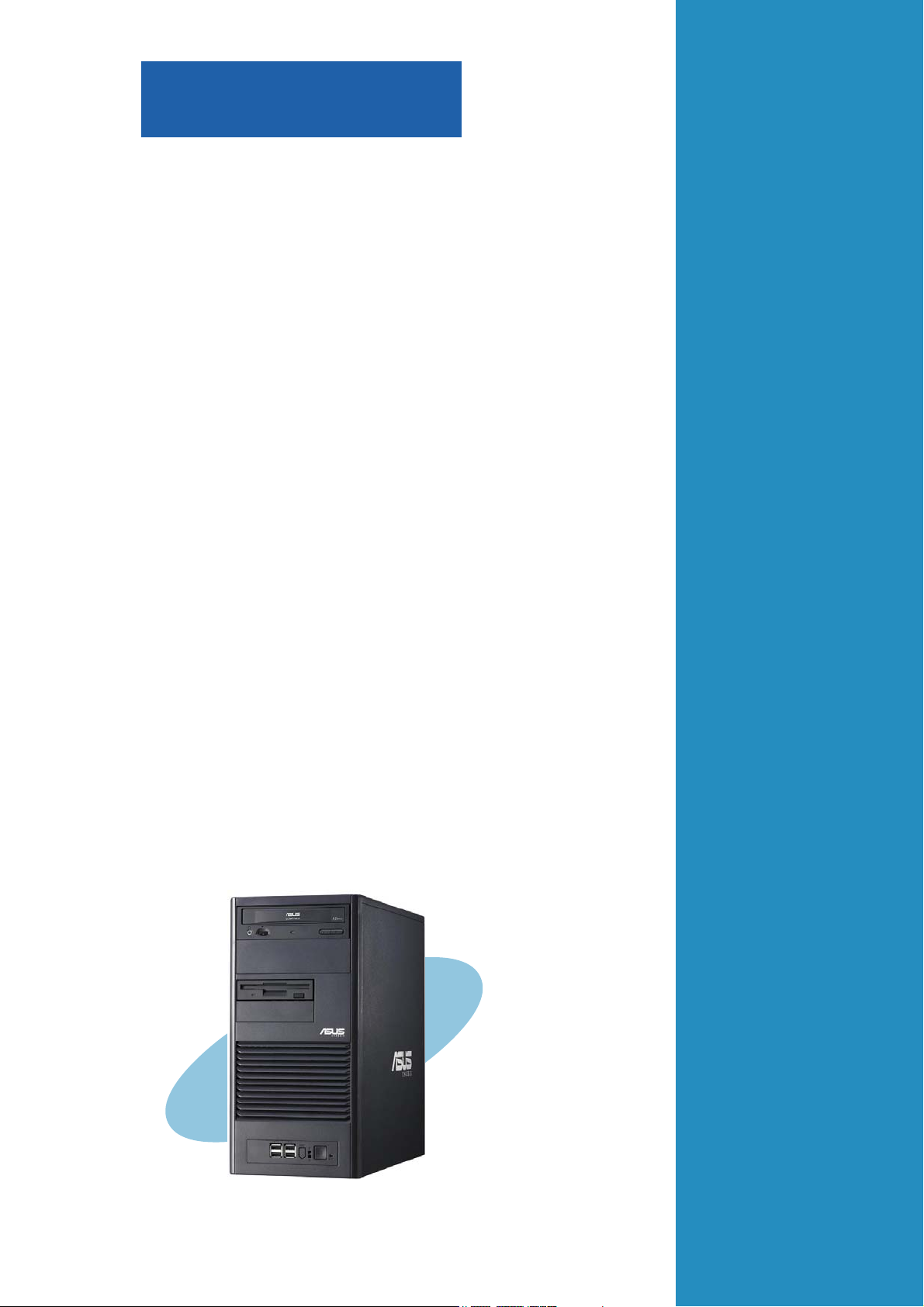
Chapter 1
This chapter describes the general
features of the barebone server,
including sections on the front
panel and rear panel specifications.
ASUS TS100-E3ASUS TS100-E3
ASUS TS100-E3
ASUS TS100-E3ASUS TS100-E3
Product introduction
1-1
Page 12

1.1 System package contents
Check your ASUS TS100-E3 package with the items on the following table.
The package contents vary for the following configurations:
Item DescriptionItem Description
Item Description
Item DescriptionItem Description
ASUS TS100-E3 pedestal chassis with:
• ASUS P5MT-MX/C motherboard
• 350 W single power supply
• Floppy disk drive
• 9 cm Blower
• Front I/O board
• CPU Cooler x1
• Dummy covers
Cables
• SATA power cable
• SATA signal cables
• IDE cables
System screws and cables
System keys ( 2 pcs.)
Bundled CDs
• TS100-E3 support CD with ASWM*
• Computer Associates® eTrust™ anti-virus CD
Documentation
• ASUS TS100-E3 user guide
• ASUS ASWM 2.0 user guide
Optional items
• 52x IDE CD-ROM or 16X DVD-ROM drive
*ASUS System Web-based Management
1-21-2
1-2
1-21-2
Chapter 1: Product introductionChapter 1: Product introduction
Chapter 1: Product introduction
Chapter 1: Product introductionChapter 1: Product introduction
Page 13

1.2 System specifications
The ASUS TS100-E3 is a barebone server system featuring the ASUS P5MT
Series motherboard. The server supports an Intel
processor in the 775-land package, and includes the latest technologies
through the chipsets embedded on the motherboard.
®
Pentium® 4/Pentium® D
ChassisChassis
Chassis
ChassisChassis
MotherboardMotherboard
Motherboard
MotherboardMotherboard
ChipsetChipset
Chipset
ChipsetChipset
ProcessorProcessor
Processor
ProcessorProcessor
Front Side BusFront Side Bus
Front Side Bus
Front Side BusFront Side Bus
MemoryMemory
Memory
MemoryMemory
LANLAN
LAN
LANLAN
Pedestal with removable front door bezel and chassis foot
stand or roller-wheels.
ASUS P5MT-MX/C
ATX compatible form factor: 9.6 in. x 9.6 in.
Northbridge: Intel
®
E7230 Memory Controller Hub (MCH)
Southbridge: Intel® ICH7R
®
Pentium® 4/Intel® Pentium® D processor in the
Intel
775-land package with Extended Memory 64-bit
Technology (EM64T)
Supports Dual Core technology
1066/800/533 MHz
Dual-channel memory architecture
4 x 240-pin DIMM sockets support ECC/non-ECC
unbuffered 667/533 MHz DDR2 memory modules
Supports 256 MB up to 8 GB of system memory
Dual Broadcom
®
BCM5721 Gigabit LAN controllers
- PCI Express 1.0a specifications compliant
StorageStorage
Storage
StorageStorage
ExpansionExpansion
Expansion
ExpansionExpansion
slotsslots
slots
slotsslots
Drive baysDrive bays
Drive bays
Drive baysDrive bays
Front panelFront panel
Front panel
Front panelFront panel
®
ICH7R Southbridge supports:
Intel
- 2 x Serial ATA 3 Gb/s hard disk drives (Supports up to
2 hard disk drives)
- LSI Logic Embedded SATA RAID controller (RAID 0,
RAID 1)
2 x PCI 33 MHz/32-bit/5V (PCI 2.3)
1 x PCI Express™ x8 slot ( x4 Link)
1 x PCI Express™ x16 slot (x8 Link)*
1 x 3.5-inch FDD bay
2 x 3.5-inch internal drive bays
2 x 5.25-inch drive bays
4 x USB 2.0 ports
(continued on the next page)
ASUS TS100-E3ASUS TS100-E3
ASUS TS100-E3
ASUS TS100-E3ASUS TS100-E3
1-31-3
1-3
1-31-3
Page 14
Rear panelRear panel
Rear panel
Rear panelRear panel
1 x Serial port
1 x Parallel port
1 x PS/2 keyboard port
1 x PS/2 mouse port
1 x LAN (RJ-45) ports
2 x USB 2.0 ports
1 x VGA port
ManagementManagement
Management
ManagementManagement
HardwareHardware
Hardware
HardwareHardware
monitorsmonitors
monitors
monitorsmonitors
Power supplyPower supply
Power supply
Power supplyPower supply
* If you install a PCI Express VGA card, the link speed downgrades to
x1 due to chipset limitation. This limitation applies only to VGA
cards.
ASUS Server Web-based Management (ASWM) 2.0
Voltage, temperature, CPU and memory utilization, storage
capacity, and fan speed monitoring
Automatic Server Restart (ASR) feature
350 W single power supply
(with 24-pin and 4-pin power plugs)
1-41-4
1-4
1-41-4
Chapter 1: Product introductionChapter 1: Product introduction
Chapter 1: Product introduction
Chapter 1: Product introductionChapter 1: Product introduction
Page 15
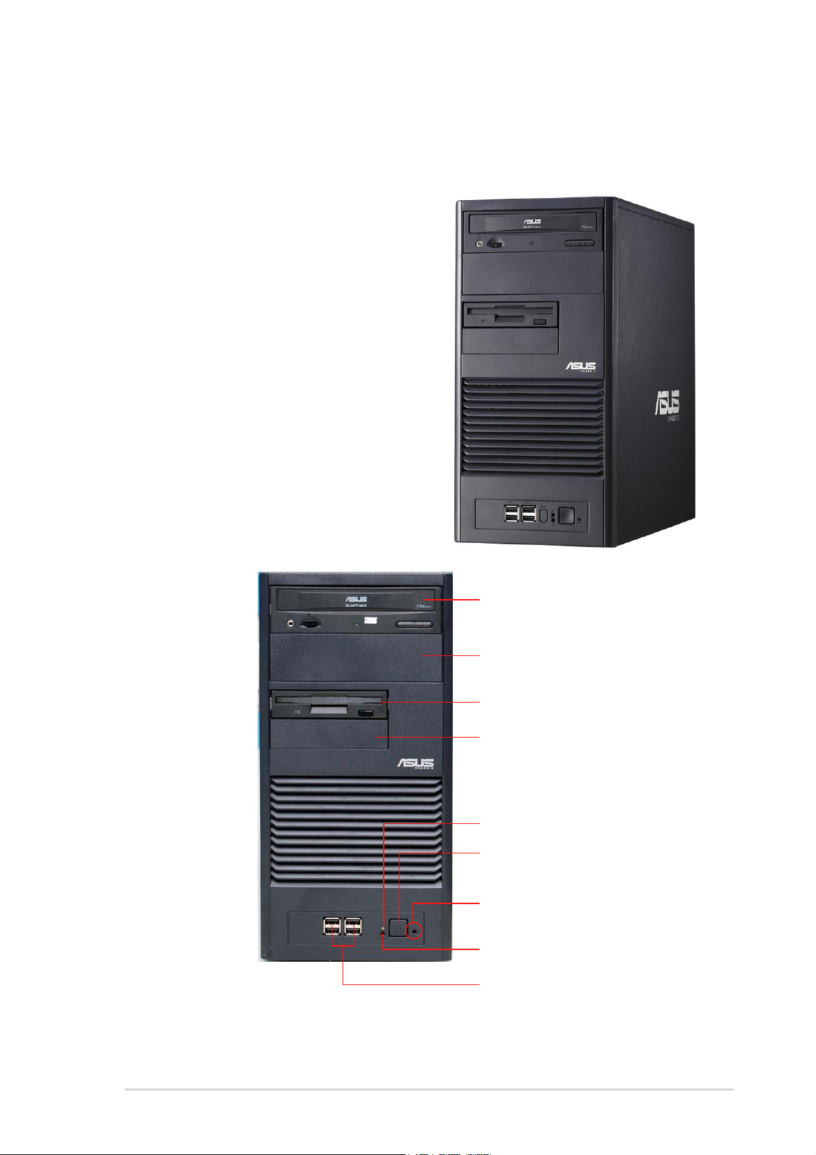
1.3 Front panel features
The TS100-E3 chassis displays a stylish front bezel with lock. The bezel
covers the system components on the front panel and serves as security.
Open the bezel to access the front panel components.
The drive bays, power and reset
buttons, LED indicators, CD-ROM drive,
floppy drive, and USB 2.0 ports are
located on the front panel. For future
installation of 5.25-inch devices, two
drive bays are available.
DVD/CDVD/C
DVD/C
DVD/CDVD/C
Empty 5.25-inch bayEmpty 5.25-inch bay
Empty 5.25-inch bay
Empty 5.25-inch bayEmpty 5.25-inch bay
Floppy disk driveFloppy disk drive
Floppy disk drive
Floppy disk driveFloppy disk drive
Empty 3.5-inch bayEmpty 3.5-inch bay
Empty 3.5-inch bay
Empty 3.5-inch bayEmpty 3.5-inch bay
Power LEDPower LED
Power LED
Power LEDPower LED
Power buttonPower button
Power button
Power buttonPower button
Reset buttonReset button
Reset button
Reset buttonReset button
HDD access LEDHDD access LED
HDD access LED
HDD access LEDHDD access LED
USB 2.0 portsUSB 2.0 ports
USB 2.0 ports
USB 2.0 portsUSB 2.0 ports
D-ROM driveD-ROM drive
D-ROM drive
D-ROM driveD-ROM drive
ASUS TS100-E3ASUS TS100-E3
ASUS TS100-E3
ASUS TS100-E3ASUS TS100-E3
1-51-5
1-5
1-51-5
Page 16
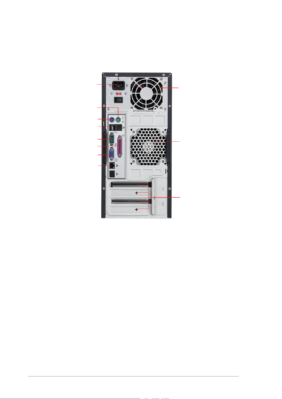
1.4 Rear panel features
The rear panel includes a slot for the motherboard rear I/O ports,
expansion slots, a chassis lock and intrusion switch, a vent for the system
fan, and power supply module.
Power Power
Power
Power Power
PS/2 mouse portPS/2 mouse port
PS/2 mouse port
PS/2 mouse portPS/2 mouse port
PS/2 keyboard portPS/2 keyboard port
PS/2 keyboard port
PS/2 keyboard portPS/2 keyboard port
RJ-45 LAN portsRJ-45 LAN ports
RJ-45 LAN ports
RJ-45 LAN portsRJ-45 LAN ports
connectorconnector
connector
connectorconnector
USB 2.0 portsUSB 2.0 ports
USB 2.0 ports
USB 2.0 portsUSB 2.0 ports
Serial portSerial port
Serial port
Serial portSerial port
Parallel portParallel port
Parallel port
Parallel portParallel port
VGA portVGA port
VGA port
VGA portVGA port
Power supply modulePower supply module
Power supply module
Power supply modulePower supply module
9 cm system fan9 cm system fan
9 cm system fan
9 cm system fan9 cm system fan
Expansion slotsExpansion slots
Expansion slots
Expansion slotsExpansion slots
1-61-6
1-6
1-61-6
Chapter 1: Product introductionChapter 1: Product introduction
Chapter 1: Product introduction
Chapter 1: Product introductionChapter 1: Product introduction
Page 17

1.5 Internal features
The barebone server system includes basic components like motherboard,
power supply, floppy disk, optical drive, and cables as shown.
55
5
55
11
1
11
66
6
66
77
7
77
22
2
22
33
3
33
88
8
88
44
4
44
1. Power supply module
2. Chassis fan
3. ASUS P5MT motherboard
4. Expansion card slots
5. Optical drive
6. 1 x 5.25-inch drive bay
7. Floppy drive
8. 2 x internal 3.5-inch drive bays
ASUS TS100-E3ASUS TS100-E3
ASUS TS100-E3
ASUS TS100-E3ASUS TS100-E3
1-71-7
1-7
1-71-7
Page 18
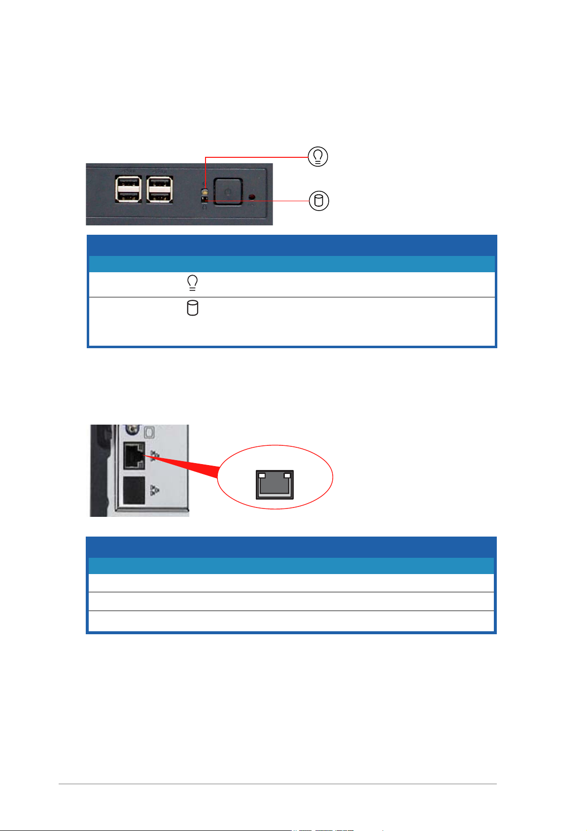
1.6 LED information
The barebone system comes with five LED indicators. Refer to the following
table for the LED status description.
System and HDD LEDSystem and HDD LED
System and HDD LED
System and HDD LEDSystem and HDD LED
Power LED (blue)Power LED (blue)
Power LED (blue)
Power LED (blue)Power LED (blue)
Drive Status LED (green/red)Drive Status LED (green/red)
Drive Status LED (green/red)
Drive Status LED (green/red)Drive Status LED (green/red)
LEDLED
LED
LEDLED
SystemSystem
System
SystemSystem
Power LED ON System power ON
Drive Status LED Green Bridge board connected to backplane
LAN port LEDsLAN port LEDs
LAN port LEDs
LAN port LEDsLAN port LEDs
IconIcon
Icon
IconIcon
Display statusDisplay status
Display status
Display statusDisplay status
Blinking System is in suspend mode
Red HDD failure
RJ-45
DescriptionDescription
Description
DescriptionDescription
Installed HDD is in good condition
SPEEDACT/LNK
1-81-8
1-8
1-81-8
ACT/LINK LEDACT/LINK LED
ACT/LINK LED
ACT/LINK LEDACT/LINK LED
StatusStatus
Status
StatusStatus
OFF NO link OFF 10 Mbps connection
GREEN Linked ORANGE 100 Mbps connection
BLINKING Data activity GREEN 1 Gbps connection
DescriptionDescription
Description
DescriptionDescription
SPEED LED SPEED LED
SPEED LED
SPEED LED SPEED LED
StatusStatus
Status
StatusStatus
Chapter 1: Product introductionChapter 1: Product introduction
Chapter 1: Product introduction
Chapter 1: Product introductionChapter 1: Product introduction
DescriptionDescription
Description
DescriptionDescription
Page 19
Chapter 2
This chapter lists the hardware setup
procedures that you have to perform when
installing or removing system components.
ASUS TS100-E3ASUS TS100-E3
ASUS TS100-E3
ASUS TS100-E3ASUS TS100-E3
Hardware setup
2-1
Page 20
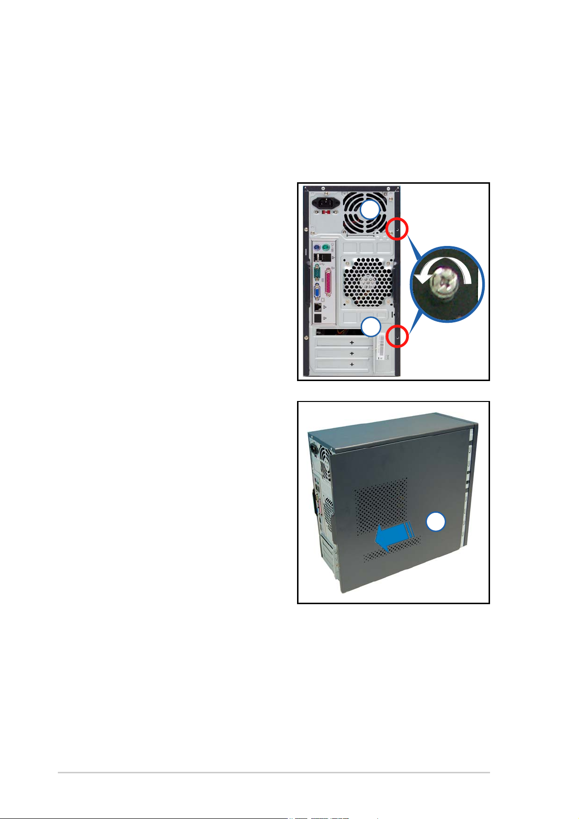
2.1 Chassis cover
The chassis features a “screwless design” that allows convenient assembly
and disassembly. You can simply push or slide mechanical bolts and locks to
remove the cover.
2.1.12.1.1
2.1.1
2.1.12.1.1
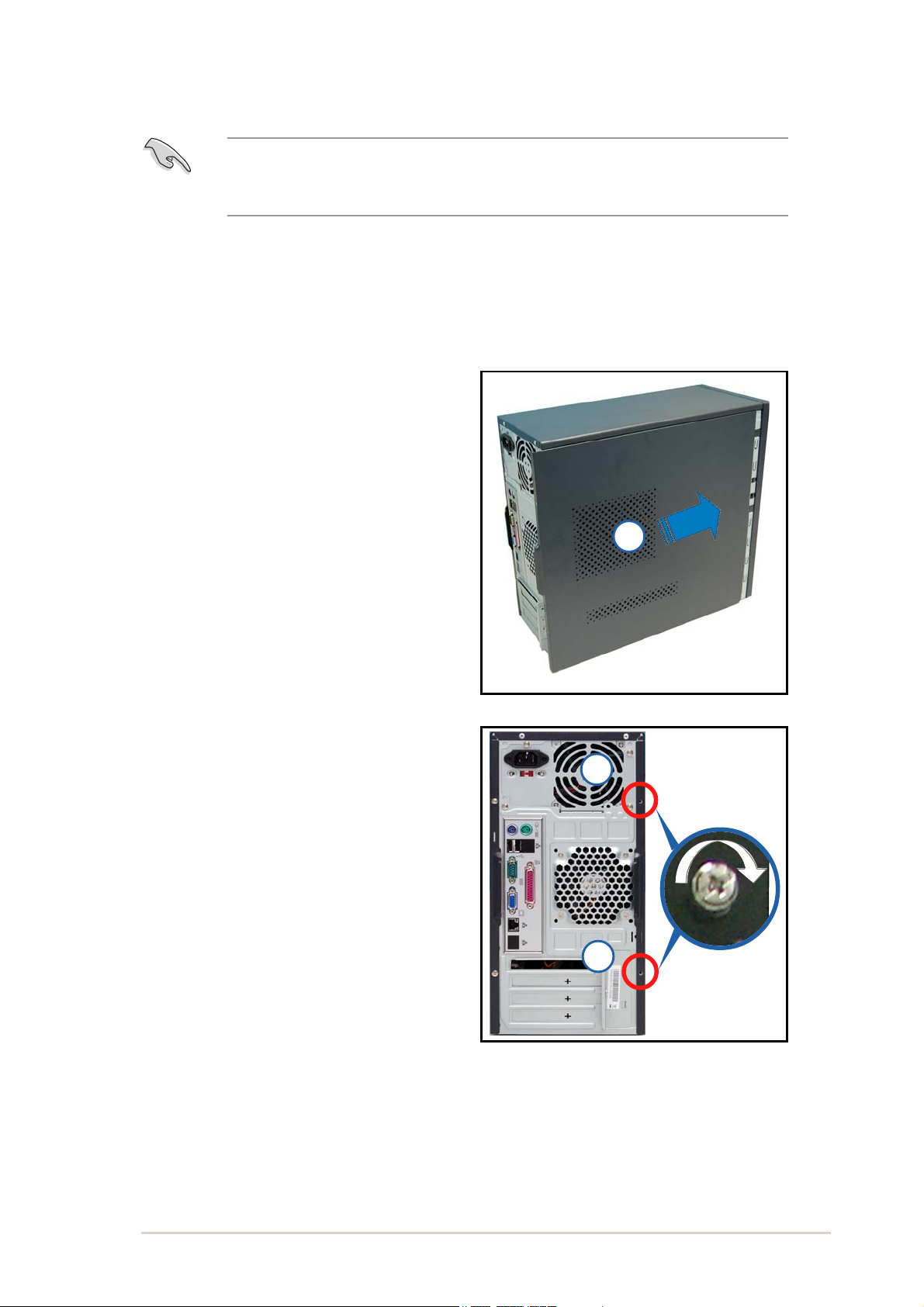
1. Remove the two screws that
secure the cover to the chassis.
2. Slide the side cover for about half
an inch toward the rear until it is
disengaged from the chassis.
Removing the side coverRemoving the side cover
Removing the side cover
Removing the side coverRemoving the side cover
11
1
11
11
1
11
3. Carefully lift the cover and set it
aside.
22
2
22
Viewing the internal structureViewing the internal structure
Viewing the internal structure
Viewing the internal structureViewing the internal structure
Without the side cover, the internal structure and installed components of
the barebone server vary depending on the model you purchased. Refer to
section “1.5 Internal features” for the different model configurations.
Perform the procedures in the succeeding sections to install the CPU, system
memory, disk drives, and expansion cards; replace fans and power supply;
and connect the system cables.
2-22-2
2-2
2-22-2
Chapter 2: Hardware setupChapter 2: Hardware setup
Chapter 2: Hardware setup
Chapter 2: Hardware setupChapter 2: Hardware setup
Page 21
You may need to remove some of the installed components to access the
DIMM sockets and internal connectors. Refer to section “2.10 Removable
components” for instructions.
2.1.22.1.2
2.1.2
2.1.22.1.2
To reinstall the side cover:
1. Match and insert the upper hooks
and lower sliding edge of the
cover to the corresponding
chassis holes and edge.
2. Slide the cover toward the front
until it snaps in place.
3. Re-screw to secure the side cover.
Reinstalling the side coverReinstalling the side cover
Reinstalling the side cover
Reinstalling the side coverReinstalling the side cover
22
2
22
11
1
11
11
1
11
ASUS TS100-E3ASUS TS100-E3
ASUS TS100-E3
ASUS TS100-E3ASUS TS100-E3
2-32-3
2-3
2-32-3
Page 22
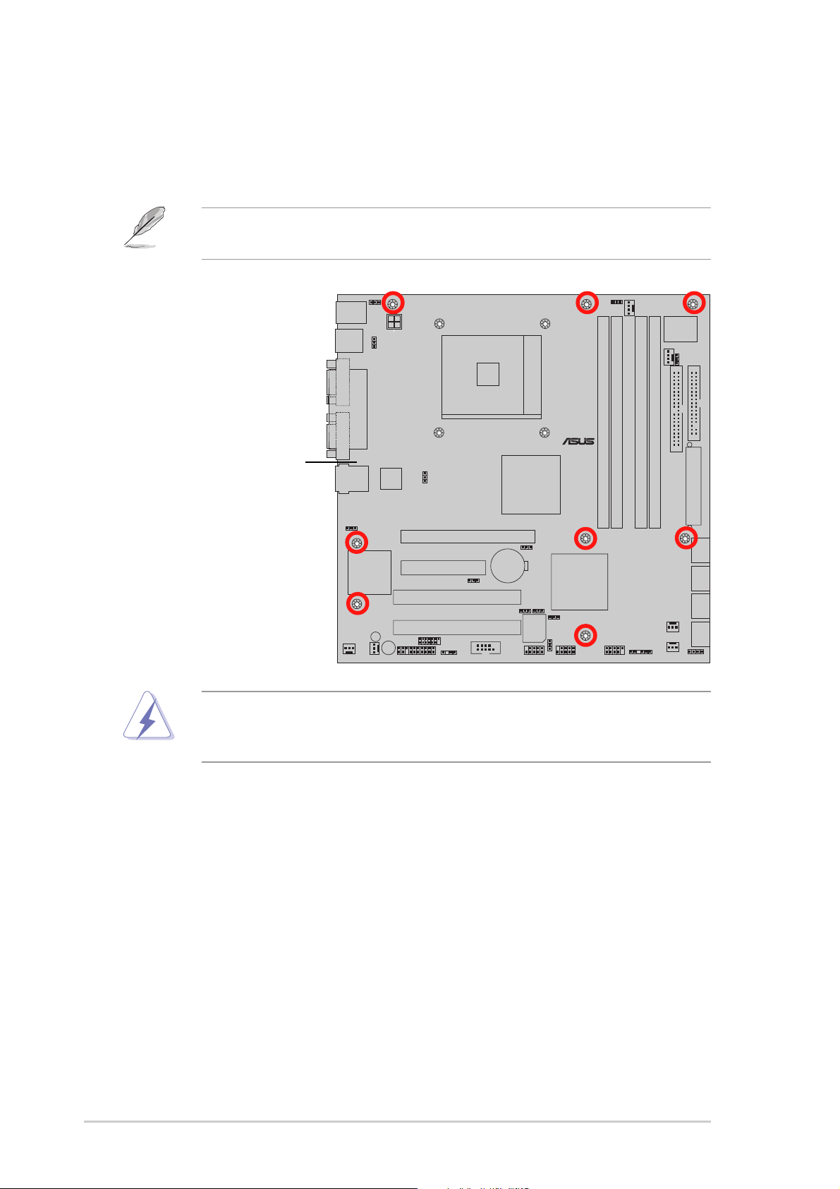
2.2 Motherboard overview
The barebone server comes with the P5MT-MX/C motherboard installed. The
motherboard is secured to the chassis by eight (8) screws as indicated by
the circles in the illustration below.
Refer to “Chapter 4 Motherboard information” for detailed information
on the motherboard.
P5MT-MX
Place this side towardsPlace this side towards
Place this side towards
Place this side towardsPlace this side towards
the rear of the chassisthe rear of the chassis
the rear of the chassis
the rear of the chassisthe rear of the chassis
Make sure to unplug the power cord before installing or removing any
motherboard components or connectionin order to avoid physical injury
and motherboard components damage.
2-42-4
2-4
2-42-4
Chapter 2: Hardware setupChapter 2: Hardware setup
Chapter 2: Hardware setup
Chapter 2: Hardware setupChapter 2: Hardware setup
Page 23
2.3 Central Processing Unit (CPU)
The motherboard comes with a surface mount LGA775 socket designed for
the Intel® Pentium® 4 processor in the 775-land package
2.3.12.3.1
2.3.1
2.3.12.3.1
Installing the CPUInstalling the CPU
Installing the CPU
Installing the CPUInstalling the CPU
To install a CPU:
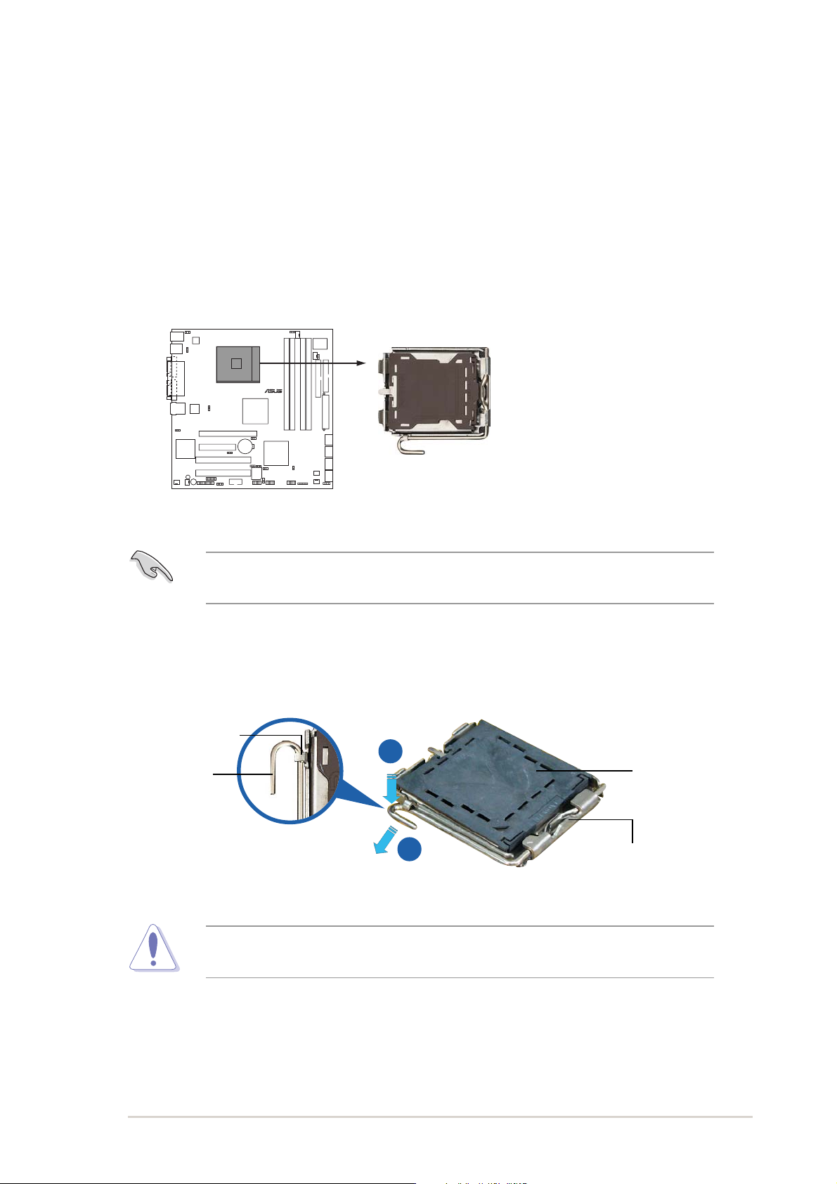
1. Locate the CPU socket on the motherboard.
P5MT-MX
P5MT-MX/C CPU Socket 775
Before installing the CPU, make sure that the cam box is facing towards
you and the load lever is on your left.
2. Press the load lever with your thumb (A), then move it to the left (B)
until it is released from the retention tab.
Retention tabRetention tab
Retention tab
Retention tabRetention tab
A
PnP capPnP cap
PnP cap
Load leverLoad lever
Load lever
Load leverLoad lever
B
To prevent damage to the socket pins, do not remove the PnP cap
unless you are installing a CPU.
This side of theThis side of the
This side of the
This side of theThis side of the
socket box shouldsocket box should
socket box should
socket box shouldsocket box should
face you.face you.
face you.
face you.face you.
PnP capPnP cap
ASUS TS100-E3ASUS TS100-E3
ASUS TS100-E3
ASUS TS100-E3ASUS TS100-E3
2-52-5
2-5
2-52-5
Page 24
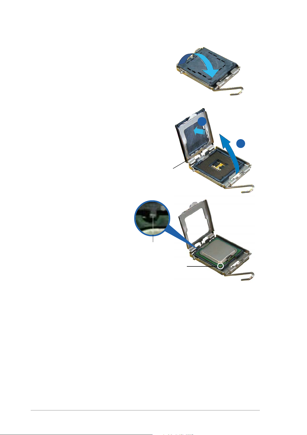
3. Lift the load lever in the direction
of the arrow to a 135º angle.
4. Lift the load plate with your thumb
and forefinger to a 100º angle (A),
then push the PnP cap from the
load plate window to remove (B).
Load plateLoad plate
Load plate
Load plateLoad plate
B
A
5. Position the CPU over the
socket, making sure that
the gold triangle is on the
bottom-left corner of the
socket. The socket
alignment key should fit
into the CPU notch.
Alignment keyAlignment key
Alignment key
Alignment keyAlignment key
Gold triangle markGold triangle mark
Gold triangle mark
Gold triangle markGold triangle mark
2-62-6
2-6
2-62-6
Chapter 2: Hardware setupChapter 2: Hardware setup
Chapter 2: Hardware setup
Chapter 2: Hardware setupChapter 2: Hardware setup
Page 25
The CPU fits in only one correct orientation. DO NOT force the CPU into the
socket. It may bend the connectors on the socket and damage the CPU!
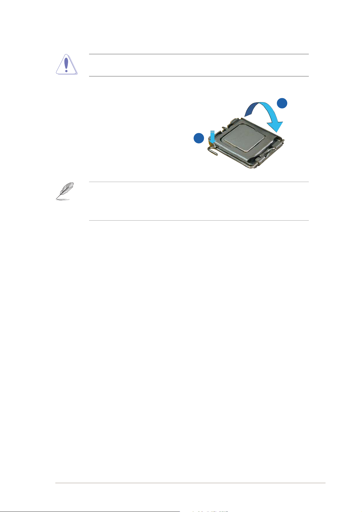
6. Close the load plate (A), then
push the load lever (B) until it
snaps into the retention tab.
The motherboard supports Intel® Pentium® 4 LGA775 processors with the
Intel® Enhanced Memory 64 Technology (EM64T), Enhanced Intel
SpeedStep® Technology (EIST), and Hyper-Threading Technology. Refer to
the Appendix for more information on these CPU features.
A
B
ASUS TS100-E3ASUS TS100-E3
ASUS TS100-E3
ASUS TS100-E3ASUS TS100-E3
2-72-7
2-7
2-72-7
Page 26
2.3.22.3.2
2.3.2
2.3.22.3.2
Installing the CPU heatsink and airductInstalling the CPU heatsink and airduct
Installing the CPU heatsink and airduct
Installing the CPU heatsink and airductInstalling the CPU heatsink and airduct
assemblyassembly
assembly
assemblyassembly
The TS100-E3 comes with a proprietary CPU heatsink. You have to assemble
the CPU heatsink before installing to the motherboard.
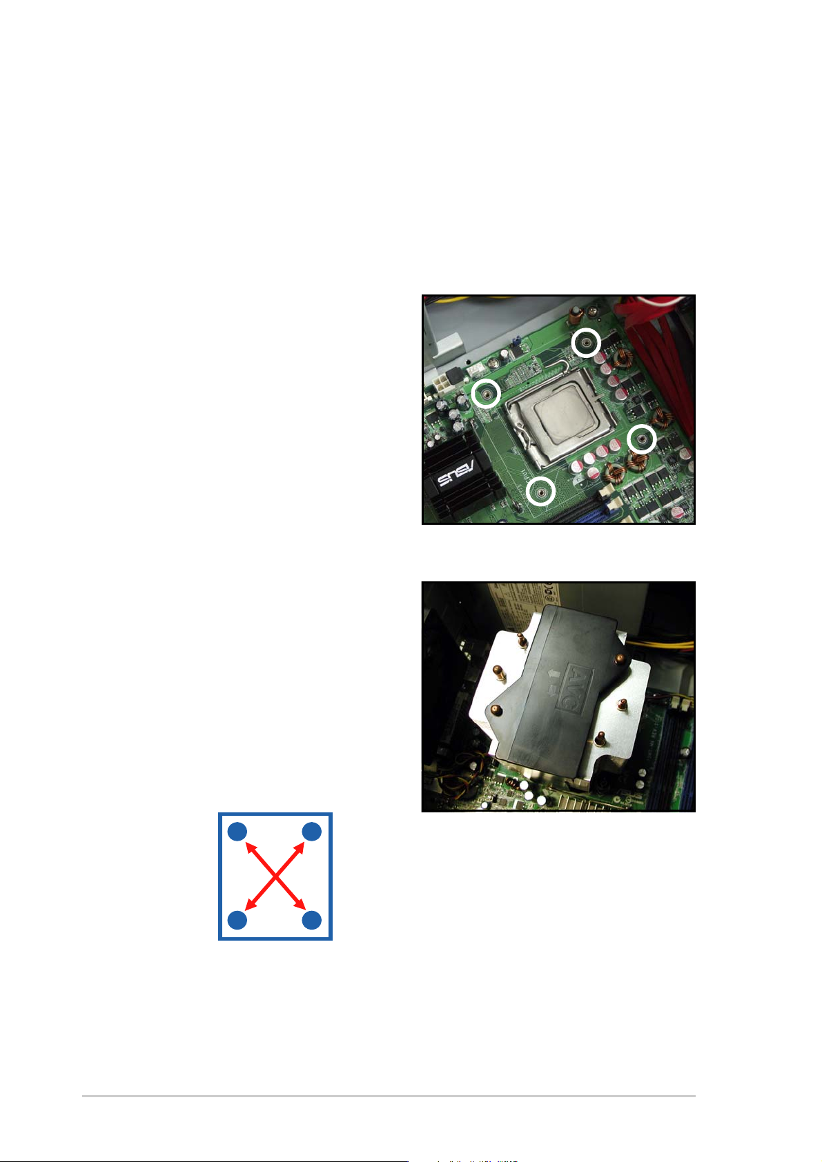
To install the CPU heatsink and airduct assembly:
1. Locate the four screw holes on
the motherboard.
2. Position the CPU heatsink and
airduct assembly on top of the
installed CPU. Make sure that the
heatsink screws match the screw
holes on the motherboard.
3. Drive the four screws into the
holes in a diagonal sequence to
secure the heatsink and airduct
assembly to the motherboard.
A
B
B
A
4. Connect the CPU fan cable to the connector on the motherboard labeled
CPU_FAN1.
2-82-8
2-8
2-82-8
Chapter 2: Hardware setupChapter 2: Hardware setup
Chapter 2: Hardware setup
Chapter 2: Hardware setupChapter 2: Hardware setup
Page 27
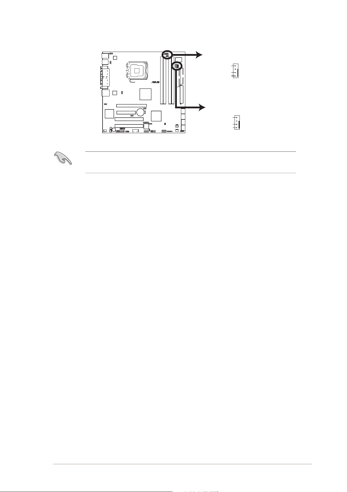
CPU_FAN2
P5MT-MX/C
®
FANOUT7
FANPWR3
GND
CPU_FAN1
FANOUT4
FANPWR2
GND
P5MT-MX/C CPU Fan Connectors
Do not forget to connect the CPU fan connector! Hardware monitoring
errors may occur if you fail to plug the connector.
ASUS TS100-E3ASUS TS100-E3
ASUS TS100-E3
ASUS TS100-E3ASUS TS100-E3
2-92-9
2-9
2-92-9
Page 28
2.4 System memory
2.4.12.4.1
2.4.1
2.4.12.4.1
OverviewOverview
Overview
OverviewOverview
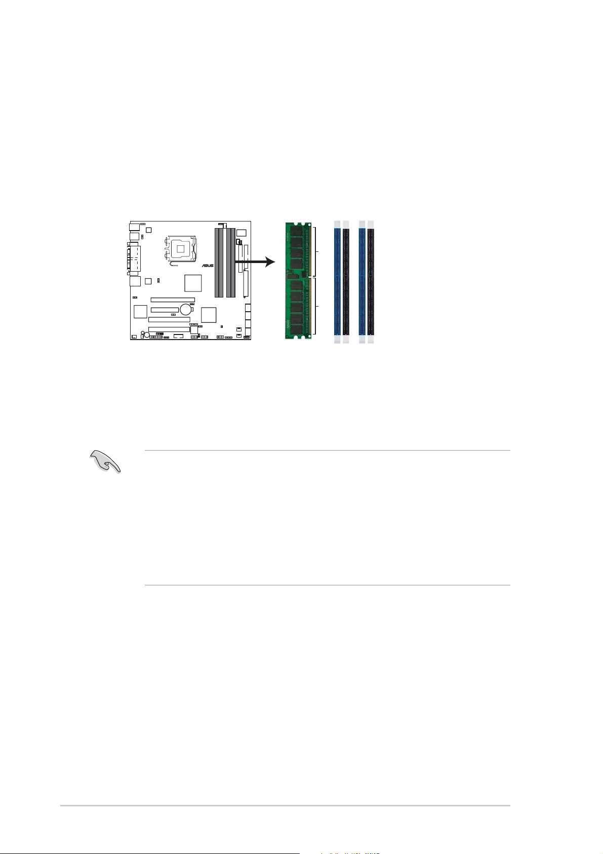
The motherboard comes with four Double Data Rate II (DDR2) Dual Inline
Memory Modules (DIMM) sockets to support 240-pin DDR modules.
The figure illustrates the location of the DDR DIMM sockets:
DIMM_A2
DIMM_B2
DIMM_B1
2.4.22.4.2
2.4.2
2.4.22.4.2
P5MT-MX/C
®
P5MT-MX/C 240-pin DDR2 DIMM Sockets
Memory configurationsMemory configurations
Memory configurations
Memory configurationsMemory configurations
DIMM_A1
112 Pins128 Pins
You may install 256 MB, 512 MB, 1 GB, and 2 GB unbuffered ECC or non-ECC
DDR2-533/667 DIMMs into the DIMM sockets.
• Always install DIMMs with the same CAS latency. For optimum
compatibility, it is recommended that you obtain memory modules
from the same vendor. Refer to the DDR2 Qualified Vendors List at the
ASUS web site.
• When installing one or two DIMMs, install the DIMM(s) to the blue slots
(DIMM_A2/DIMM_B2).
• Three DDR DIMMs intalled into any three memory sockets will function
in single-channel mode.
2-102-10
2-10
2-102-10
Chapter 2: Hardware setupChapter 2: Hardware setup
Chapter 2: Hardware setup
Chapter 2: Hardware setupChapter 2: Hardware setup
Page 29
2.4.32.4.3
2.4.3
2.4.32.4.3
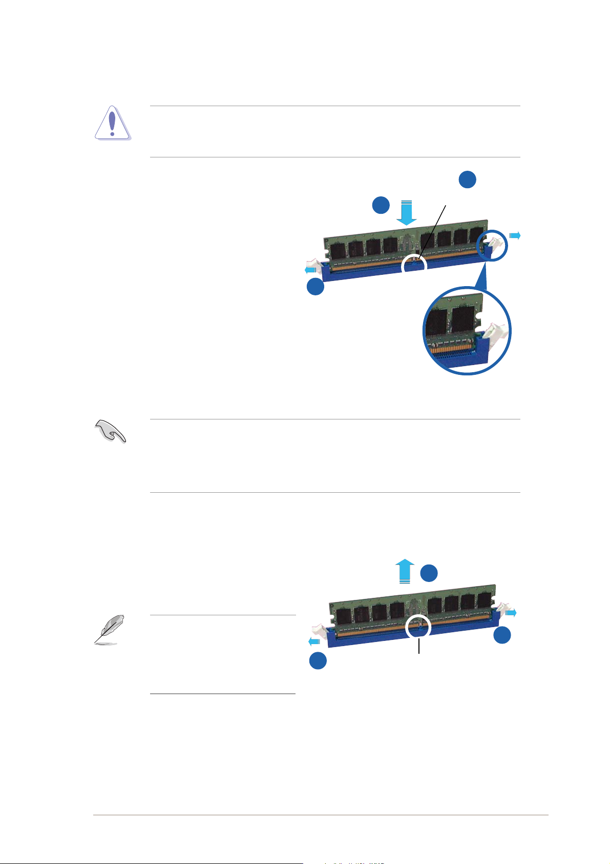
Installing a DIMMInstalling a DIMM
Installing a DIMM
Installing a DIMMInstalling a DIMM
Unplug the power supply before adding or removing DIMMs or other system
components. Failure to do so may cause severe damage to both the
motherboard and the components.
To install a DIMM:
1. Unlock a DIMM socket by
pressing the retaining clips
outward.
2. Align a DIMM on the socket so
that the notch on the DIMM
matches the break on the
socket.
3. Firmly insert the DIMM into the
socket until the retaining clips
snap back in place and the DIMM
is properly seated.
• A DDR2 DIMM is keyed with a notch so that it fits in only one direction.
Do not force a DIMM into a socket to avoid the DIMM damage.
• The DDR2 DIMM sockets do not support DDR DIMMs. DO not install
DDR DIMMs to the DDR2 DIMM sockets.
2
DDR2 DIMM notchDDR2 DIMM notch
DDR2 DIMM notch
3
1
Unlocked retaining clipUnlocked retaining clip
Unlocked retaining clip
Unlocked retaining clipUnlocked retaining clip
DDR2 DIMM notchDDR2 DIMM notch
2.4.42.4.4
2.4.4
2.4.42.4.4
Removing a DIMMRemoving a DIMM
Removing a DIMM
Removing a DIMMRemoving a DIMM
To remove a DIMM:
1. Simultaneously press the retaining
clips outward to unlock the DIMM.
Support the DIMM lightly with
your fingers when pressing
the retaining clips. The DIMM
might get damaged when it
flips out with extra force.
1
2. Remove the DIMM from the socket.
2
DDR2 DIMM notchDDR2 DIMM notch
DDR2 DIMM notch
DDR2 DIMM notchDDR2 DIMM notch
1
ASUS TS100-E3ASUS TS100-E3
ASUS TS100-E3
ASUS TS100-E3ASUS TS100-E3
2-112-11
2-11
2-112-11
Page 30
2.5 Expansion slots
In the future, you may need to install expansion cards. The following subsections describe the slots and the expansion cards that they support.
Make sure to unplug the power cord before installing or removing expansion
cards. Failure to do so may cause physical injury, and damage to the cards
and motheboard components!
2.5.12.5.1
2.5.1
2.5.12.5.1
To install an expansion card:
1. Before installing the expansion card, read the documenttation that came
with it and make the necessary hardware settings for the card.
2. Remove the system unit cover (if your motherboard is already installed
in a chassis)
3. Remove the bracket opposite the slot that you intend to use. Keep the
screw for later use.
4. Align the card connector with the slot and press firmly until the card is
completely seated on the slot.
5. Secure the card to the chassis with the screw you removed earlier.
6. Replace the system cover.
2.5.22.5.2
2.5.2
2.5.22.5.2
After installing the expansion card, configure it by adjusting the software
settings:
Installing an expansion cardInstalling an expansion card
Installing an expansion card
Installing an expansion cardInstalling an expansion card
Configuring an expansion cardConfiguring an expansion card
Configuring an expansion card
Configuring an expansion cardConfiguring an expansion card
1. Turn on the system and change the necessary BIOS settings, if any.
2. Assign an IRQto the card. Refer to the tables on the next page.
3. Install the software drivers for the expansion card.
When using PCI cards on shared slots, ensure that the drivers support
“Shared IRQ” or that the cards do not need IRQ assignments. Otherwise,
conflicts will arise between the two PCI groups, making the system
unstableand the card inoperable.
2-122-12
2-12
2-122-12
Chapter 2: Hardware setupChapter 2: Hardware setup
Chapter 2: Hardware setup
Chapter 2: Hardware setupChapter 2: Hardware setup
Page 31

2.5.32.5.3
2.5.3
2.5.32.5.3
Standard interrupt assignmentsStandard interrupt assignments
Standard interrupt assignments
Standard interrupt assignmentsStandard interrupt assignments
IRQ Priority Standard Function
0 1 System Timer
1 2 Keyboard Controller
2 - Re-direct to IRQ #9
3* 11 Communications Port (COM2)
4* 12 Communications Port (COM1)
5* 13 IRQ holder for PCI steering
6 14 Floppy Disk Controller
7* 15 Printer Port (LPT1)
8 3 System CMOS/REAL Time Clock
9* 4 IRQ holder for PCI steering
10* 5 IRQ holder for PCI steering
11* 6 IRQ holder for PCI steering
12* 7 PS/2 Compatiable Mouse Port
13 8 Numeric Data Processor
14 9 Primary IDE Channel
15 10 Secondary IDE Channel
Interrupt assignmentsInterrupt assignments
Interrupt assignments
Interrupt assignmentsInterrupt assignments
* These IRQs are usually available forISA or PCI devices.
PCI Bus Number, IDSEL, and IRQ assignments
Description INTA INTB INTC INTD REQ# GNT#
PCI slot 1 PIRQE# PIRQF# PIRQG# PIRQH# REQ0# GNT0#
PCI slot 2 PIRQG# PIRQH# PIRQE# PIRQF# REQ1# GNT1#
PCIE x 16 slot PIRQA# PIRQB# PIRQC# PIRQD#
PCIE x 8 slot PIRQA# PIRQB# PIRQC# PIRQD#
Onboard USB controller 0 PIRQA#
Onboard USB controller 1 PIRQB#
Onboard USB controller 2 PIRQC#
Onboard USB controller 3 PIRQD#
USB 2.0 EHCI controller PIRQA#
Onboard IDE port PIRQC#
Onboard SATA port PIRQD#
ATI RAGE XL PIRQE# REQ2# GNT2#
SMBUS Controller PIRQD#
Onboard LAN PIRQB#
When using PCI cards on shared slots, ensure that the drivers support
“Shared IRQ” or that the cards do not need IRQ assignments. Otherwise,
conflicts will arise between the two PCI groups, making the system
unstableand the card inoperable.
ASUS TS100-E3ASUS TS100-E3
ASUS TS100-E3
ASUS TS100-E3ASUS TS100-E3
2-132-13
2-13
2-132-13
Page 32
2.5.42.5.4
2.5.4
2.5.42.5.4
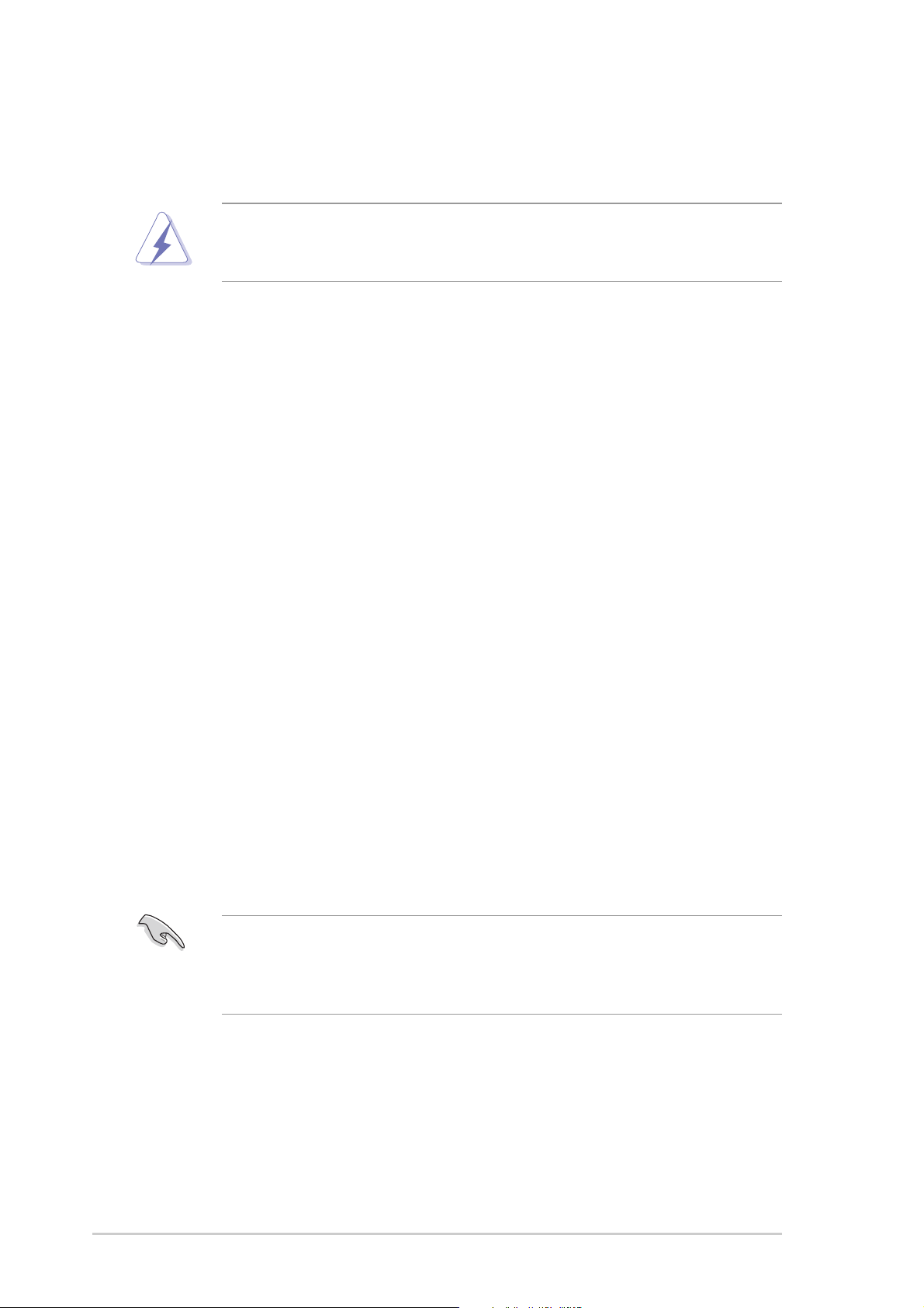
PCI Express slotPCI Express slot
PCI Express slot
PCI Express slotPCI Express slot
This motherboard supports PCI
Express network cards, SCSI cards,
and other cards that comply with PCI
Express 1.0a specifications.
Due to the limits of chipset, if users install a PCI Express X16 graphic card,
the link speed will downgrade to x1.
2.5.52.5.5
2.5.5
2.5.52.5.5
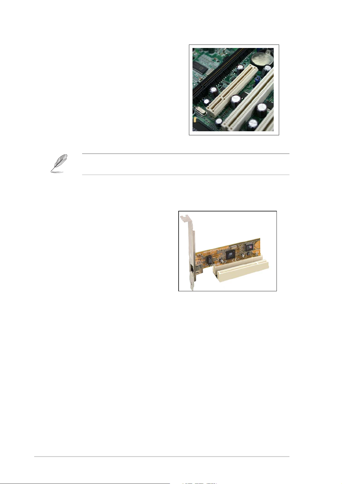
PCI slotsPCI slots
PCI slots
PCI slotsPCI slots
The PCI slots support cards such as
a LAN card, SCSI card, USB card,
and other cards that comply with PCI
2.3 specifications. The figure shows a
LAN card installed on a 32-bit PCI slot.
2-142-14
2-14
2-142-14
Chapter 2: Hardware setupChapter 2: Hardware setup
Chapter 2: Hardware setup
Chapter 2: Hardware setupChapter 2: Hardware setup
Page 33

2.6 Front panel assembly
2.6.12.6.1
2.6.1
2.6.12.6.1
To remove the front panel assembly:
1. Locate the four hooked tabs on the
chassis side rail.
2. Press each lock tab to release the
front panel from the chassis.
Removing the front panel assemblyRemoving the front panel assembly
Removing the front panel assembly
Removing the front panel assemblyRemoving the front panel assembly
Before installing a 5.25-inch drive, you should first remove the front panel
assembly (front bezel and front panel cover). The front panel assembly is
attached to the chassis through three
hinge-like tabshinge-like tabs
three
hinge-like tabs on the right side.
hinge-like tabshinge-like tabs
hooked tabshooked tabs
hooked tabs on the left side and
hooked tabshooked tabs
3. Pull and swing the left edge of the
front panel outward.
ASUS TS100-E3ASUS TS100-E3
ASUS TS100-E3
ASUS TS100-E3ASUS TS100-E3
2-152-15
2-15
2-152-15
Page 34

4. Unhook the hinge-like tabs from the holes on the right side of the front
panel to completely detach the front panel assembly from the chassis.
Do not use too much force when removing the front panel assembly.
Hinge-like tabHinge-like tab
Hinge-like tab
Hinge-like tabHinge-like tab
2-162-16
2-16
2-162-16
Chapter 2: Hardware setupChapter 2: Hardware setup
Chapter 2: Hardware setup
Chapter 2: Hardware setupChapter 2: Hardware setup
Page 35

2.6.22.6.2
2.6.2
2.6.22.6.2
To reinstall the front panel assembly (front bezel and front panel cover):
1. Insert the three hinge-like tabs to the holes on the right edge of the
chassis.
2. Swing the front panel to the left and fit the three hooked tabs to the
left side of the chassis until the tabs snap back in place.
Reinstalling the front panel assemblyReinstalling the front panel assembly
Reinstalling the front panel assembly
Reinstalling the front panel assemblyReinstalling the front panel assembly
11
1
11
Hinge-like tabHinge-like tab
Hinge-like tab
Hinge-like tabHinge-like tab
11
1
11
11
1
11
22
2
22
ASUS TS100-E3ASUS TS100-E3
ASUS TS100-E3
ASUS TS100-E3ASUS TS100-E3
2-172-17
2-17
2-172-17
Page 36

2.7 5.25-inch drives
If you have powered up the system, make sure to unplug the AC power
cable before installing or removing any system components. Failure to do
so may cause damage to the motherboard and other system components!
Two 5.25-inch drive bays are located
on the upper front part of the chassis.
A CD-ROM drive that comes standard
with the system package occupies the
uppermost bay
bay
additional 5.25-inch device.
(labeled 2)
(labeled 1)
is available for
. The other
11
1
11
22
2
22
To install a 5.25-inch drive:
1. Use a Phillips (cross) screwdriver
or one finger to remove the metal
cover of the bay where you want
to install the drive.
2. Insert the optical drive into the
5.25-inch drive bay.
2-182-18
2-18
2-182-18
Chapter 2: Hardware setupChapter 2: Hardware setup
Chapter 2: Hardware setup
Chapter 2: Hardware setupChapter 2: Hardware setup
Page 37

3. Make sure that the drive and bay
hole align as shown. When in
place, the drive protrudes about
an inch from the front panel.
4. Secure the drive with a screw.
5. Connect the IDE cable to the IDE
connector on the back of the
drive.
6. Connect a 4-pin plug from the
power supply to the power
connector on the back of the
drive.
IDE cableIDE cable
IDE cable
IDE cableIDE cable
Power plugPower plug
Power plug
Power plugPower plug
ASUS TS100-E3ASUS TS100-E3
ASUS TS100-E3
ASUS TS100-E3ASUS TS100-E3
2-192-19
2-19
2-192-19
Page 38

7. On the front panel assembly, detach the plastic bay cover opposite the
5.25-inch drive that you installed by pressing the two hooked tabs on
each side of the bay cover.
8. Reinstall the front panel assembly when done. Refer to section “2.5.2
Reinstalling the front panel assembly” for instructions.
2-202-20
2-20
2-202-20
Chapter 2: Hardware setupChapter 2: Hardware setup
Chapter 2: Hardware setup
Chapter 2: Hardware setupChapter 2: Hardware setup
Page 39

2.8 Hard disk drives
2.8.12.8.1
2.8.1
2.8.12.8.1
Follow the instructions in this section to remove a SATA hard disk drive (HDD).
1. First remove both side covers.
2. Then, unplug the SATA signal and
power cables.
3. Unscrew the SATA HDD.
Removing a SATA HDDRemoving a SATA HDD
Removing a SATA HDD
Removing a SATA HDDRemoving a SATA HDD
4. Remove the SATA HDD from the
bay.
ASUS TS100-E3ASUS TS100-E3
ASUS TS100-E3
ASUS TS100-E3ASUS TS100-E3
2-212-21
2-21
2-212-21
Page 40

2.8.22.8.2
2.8.2
2.8.22.8.2
Follow the instructions in this section to install a SATA hard disk drive (HDD).
1. First remove both side covers.
2. Then, install the SATA HDD.
Installing a SATA HDDInstalling a SATA HDD
Installing a SATA HDD
Installing a SATA HDDInstalling a SATA HDD
3. Secure the SATA HDD with
screws.
4. Connect the SATA signal and
power cables.
2-222-22
2-22
2-222-22
Chapter 2: Hardware setupChapter 2: Hardware setup
Chapter 2: Hardware setup
Chapter 2: Hardware setupChapter 2: Hardware setup
Page 41

2.9 Expansion cards
Refer to this section when installing expansion cards.
Make sure to unplug the power cord before installing or removing expansion
cards. Failure to do so may cause physical injury, and damage to the cards
and motheboard components!
2.9.12.9.1
2.9.1
2.9.12.9.1
To install an expansion card:
1. Lay the chassis on its side.
2. Locate the metal bracket opposite
the slot you want to use.
3. Remove the screw that secures
the metal bracket to the chassis.
Set aside the metal bracket for
future use.
Installing an expansion cardInstalling an expansion card
Installing an expansion card
Installing an expansion cardInstalling an expansion card
4. Remove the metal bracket with the
screwdriver.
5. Align the card golden fingers to the
slot and its metal bracket to the
slot opening on the chassis.
6. Press the card firmly until it is
properly seated on the slot.
ASUS TS100-E3ASUS TS100-E3
ASUS TS100-E3
ASUS TS100-E3ASUS TS100-E3
2-232-23
2-23
2-232-23
Page 42

7. After installing the expansion card,
put the metal bracket back.
8. Adjust the metal bracket to the
locking pawl and screw it tightly.
2-242-24
2-24
2-242-24
Chapter 2: Hardware setupChapter 2: Hardware setup
Chapter 2: Hardware setup
Chapter 2: Hardware setupChapter 2: Hardware setup
Page 43

2.9.22.9.2
2.9.2
2.9.22.9.2
To remove an expansion card:
1. Remove the side cover.
2. Lay the chassis on its side.
3. For removing an expansion card,
unscrew the metal bracket and
remove it.
Removing an expansion cardRemoving an expansion card
Removing an expansion card
Removing an expansion cardRemoving an expansion card
4. Carefully remove the seated
expansion card from the
motherboard slot.
5. After removing the expansion
card, re-screw the metal bracket
to its original position.
ASUS TS300-E3ASUS TS300-E3
ASUS TS300-E3
ASUS TS300-E3ASUS TS300-E3
2-252-25
2-25
2-252-25
Page 44

2.10 Cable connections
• The bundled system cables are pre-connected before shipped. You do
not need to disconnect these cables unless you need to remove
pre-installed components for additional device installation.
• Refer to Chapter 4 for detailed information on the connectors.
2.10.12.10.1
2.10.1
2.10.12.10.1
PS/2KBMS
T: Mouse
B: Keyboard
COM1
VGA1
44
4
44
REAR_FAN2
Motherboard connectionsMotherboard connections
Motherboard connections
Motherboard connectionsMotherboard connections
24.5cm (9.6in)
USB12
LAN1
ATI RageXL
KBPWR
USBPW12
PARALLEL PORT
VGA_EN1
SB_PWR1
REAR_FAN1
ATX12V1
Broadcd
BCM5753
BUZZ1
J1
22
2
22
LAN_EN1
PANEL1
PCIE2
PCI1
PCI2
CHASSIS1
CLRTC1
LGA775
PCIE1
CR2032 3
Lithium Cell
CMOS Powe
RECOVERY1
COM2
Intel E7230
RAID_SEL1
8Mb
FWH
USB34
Intel ICH7R
USBPW56
USBPW34
USBPW78
USB56
FM_CPU2
CPU_FAN2
33
3
33
SUPER I/O
CPU_FAN1
33
3
33
P5MT-MX/C
®
DDR2 DIMM_A2 (64 bit,240-pin module)
DDR2 DIMM_A1 (64 bit,240-pin module)
USB78
DDR2 DIMM_B1 (64 bit,240-pin module)
TRPWR1
55
5
55
BPSMB1
FM_CPU1
PRI_IDE1
DDR2 DIMM_B2 (64 bit,240-pin module)
11
1
11
FRNT_FAN1
FRNT_FAN2
HDLED1
1010
10
1010
1111
11
1111
FLOPPY1
ATXPWR1
SATA4SATA3SATA1 SATA2
24.5cm (9.6in)
66
6
66
77
99
9
99
Standard cables connected to the motherboardStandard cables connected to the motherboard
Standard cables connected to the motherboard
Standard cables connected to the motherboardStandard cables connected to the motherboard
1. 24-pin ATX power
2. 4-pin 12V power
3. CPU fan 1/2
4. Rear fan 1/2
5. Front fan 1/2
7
77
88
8
88
7. Serial port (COM2)
8. Front USB cable
9. Front panel cable
10. Floppy disk drive
11. Primary IDE cable
6. Serial ATA connectors
2-262-26
2-26
2-262-26
Chapter 2: Hardware setupChapter 2: Hardware setup
Chapter 2: Hardware setup
Chapter 2: Hardware setupChapter 2: Hardware setup
Page 45

2.11 Removable components
You may need to remove previously installed system components when
installing, removing system devices, or when replacing defective components.
This section tells how to remove the following components:
1. Chassis fan
2. Floppy disk drive module
3. Front I/O board
4. Power supply unit
2.11.12.11.1
2.11.1
2.11.12.11.1
To remove the chassis fan:
1. Unplug the chassis fan cable fon
the REAR_FAN1 connector on the
motherboard.
2. Locate the four screws that
secure the fan to the chassis.
3. Remove the four screws while
carefully supporting the chassis
fan with your free hand to prevent
it from falling off.
Chassis fanChassis fan
Chassis fan
Chassis fanChassis fan
Set the screws aside.
4. Carefully remove the chassis fan.
ASUS TS300-E3ASUS TS300-E3
ASUS TS300-E3
ASUS TS300-E3ASUS TS300-E3
2-272-27
2-27
2-272-27
Page 46

To reinstall the chassis fan:
1. Align the chassis fan holes to the
screw holes on the chassis.
2. Drive in the four screws you
removed earlier to secure the fan
to the chassis.
3. Plug the chassis fan cable to the
connector on the motherboard.
2-282-28
2-28
2-282-28
Chapter 2: Hardware setupChapter 2: Hardware setup
Chapter 2: Hardware setup
Chapter 2: Hardware setupChapter 2: Hardware setup
Page 47

2.11.22.11.2
2.11.2
2.11.22.11.2
Floppy disk driveFloppy disk drive
Floppy disk drive
Floppy disk driveFloppy disk drive
You need to remove the front panel assembly before you can remove the
floppy disk drive. Refer to section “2.5.1 Removing the front panel assembly”
for instructions.
To remove the floppy disk drive:
1. Disconnect the floppy disk cable
and power cable from the drive
to completely release the drive.
Floppy drive power cableFloppy drive power cable
Floppy drive power cable
Floppy drive power cableFloppy drive power cable
Floppy drive signal cableFloppy drive signal cable
Floppy drive signal cable
Floppy drive signal cableFloppy drive signal cable
Red stripe to match Pin 1 onRed stripe to match Pin 1 on
Red stripe to match Pin 1 on
Red stripe to match Pin 1 onRed stripe to match Pin 1 on
the connectorthe connector
the connector
the connectorthe connector
2. Remove the screw that secures
the floppy disk.
3. Carefully pull out the drive from
the chassis.
ASUS TS300-E3ASUS TS300-E3
ASUS TS300-E3
ASUS TS300-E3ASUS TS300-E3
2-292-29
2-29
2-292-29
Page 48

To install a floppy disk drive:
1. Position the floppy drive into the
chassis until the drive fits the
front edge of the bay.
2. Screw the floppy disk drive tightly.
3. Connect the drive signal cable and
power cable.
2-302-30
2-30
2-302-30
Floppy drive power cableFloppy drive power cable
Floppy drive power cable
Floppy drive power cableFloppy drive power cable
Floppy drive signal cableFloppy drive signal cable
Floppy drive signal cable
Floppy drive signal cableFloppy drive signal cable
Red stripe to match Pin 1 onRed stripe to match Pin 1 on
Red stripe to match Pin 1 on
Red stripe to match Pin 1 onRed stripe to match Pin 1 on
the connectorthe connector
the connector
the connectorthe connector
Chapter 2: Hardware setupChapter 2: Hardware setup
Chapter 2: Hardware setup
Chapter 2: Hardware setupChapter 2: Hardware setup
Page 49

2.11.32.11.3
2.11.3
2.11.32.11.3
To remove the front I/O board:
1. First, remove all the connected
cables respectively.
Front I/O boardFront I/O board
Front I/O board
Front I/O boardFront I/O board
You need to remove the front panel assembly before you can remove the
front I/O board. Refer to section “2.5.1 Removing the front panel assembly”
for instructions.
2. Then, unscrew the front I/O
board.
3. Last, remove the front I/O board
from the chassis with caution.
ASUS TS300-E3ASUS TS300-E3
ASUS TS300-E3
ASUS TS300-E3ASUS TS300-E3
2-312-31
2-31
2-312-31
Page 50

To install the front I/O board:
1. First, put the front I/O board into
the chassis with caution.
2. Then, fasten the he front I/O
board with screws.
3. Last, connect all the cables to the
board respectively.
2-322-32
2-32
2-322-32
Chapter 2: Hardware setupChapter 2: Hardware setup
Chapter 2: Hardware setup
Chapter 2: Hardware setupChapter 2: Hardware setup
Page 51

2.11.42.11.4
2.11.4
2.11.42.11.4
Refer to this section when removing or installing a power supply unit to the
barebone system.
Power supply unitPower supply unit
Power supply unit
Power supply unitPower supply unit
You MUST disconnect all power cable plugs from the motherboard along
with installed devices before removing the power supply unit.
33
3
33
44
4
22
2
22
44
1. 24-pin ATX
2. 4-pin +12V
3. 4-pin plug
4. 4-pinplug
Make sure to unplug
removing the power supply unit.
(motherboard power connector)
(motherboard power connector)
(optical drive)
(floppy disk drive)
ALL ALL
ALL power cables from the system devices before
ALL ALL
11
1
11
ASUS TS300-E3ASUS TS300-E3
ASUS TS300-E3
ASUS TS300-E3ASUS TS300-E3
2-332-33
2-33
2-332-33
Page 52

To remove the power supply unit (PSU):
1. Remove the chassis cover. Refer to section “2.1.1 Removing the side
cover.”
2. Remove the front panel assembly. Refer to section “2.5.1 Removing the
front panel assembly.
3. Lay the chassis on a flat, stable
surface.
4. Disconnect all the power plug to
the connector inside the case.
5. Locate and remove the screws
that secure the PSU bracket to
the chassis.
6. Slide the bracket in the direction
of the arrow and remove it from
the chassis.
2-342-34
2-34
2-342-34
Chapter 2: Hardware setupChapter 2: Hardware setup
Chapter 2: Hardware setup
Chapter 2: Hardware setupChapter 2: Hardware setup
Page 53

To reinstall the power supply unit:
1. Remove the chassis cover. Refer to section “2.1.1 Removing the side
cover.”
2. Remove the front panel assembly. Refer to section “2.5.1 Removing the
front panel assembly.
3. Lay the chassis on a flat, stable
surface.
4. Carefully slide the PSU in the
direction of the arrow.
5. Secure the PSU to the chassis
with the four screws you removed
earlier.
6. Re-connect all the power plug to
the connector inside the case.
ASUS TS300-E3ASUS TS300-E3
ASUS TS300-E3
ASUS TS300-E3ASUS TS300-E3
2-352-35
2-35
2-352-35
Page 54

2-362-36
2-36
2-362-36
Chapter 2: Hardware setupChapter 2: Hardware setup
Chapter 2: Hardware setup
Chapter 2: Hardware setupChapter 2: Hardware setup
Page 55

Chapter 3
This chapter gives information about
the motherboard that comes with the
server. This chapter includes the
motherboard layout, jumper settings,
and connector locations.
ASUS TS100-E3ASUS TS100-E3
ASUS TS100-E3
ASUS TS100-E3ASUS TS100-E3
Motherboard info
3-1
Page 56

3.1 Motherboard layouts
P5MT-MX/C modelP5MT-MX/C model
P5MT-MX/C model
P5MT-MX/C modelP5MT-MX/C model
24.5cm (9.6in)
PS/2KBMS
T: Mouse
B: Keyboard
USB12
COM1
VGA1
LAN1
ATI RageXL
REAR_FAN2
KBPWR
USBPW12
PARALLEL PORT
VGA_EN1
SB_PWR1
REAR_FAN1
ATX12V1
Broadcd
BCM5753
BUZZ1
J1
LAN_EN1
PANEL1
PCIE2
CHASSIS1
CLRTC1
PCI1
PCI2
LGA775
PCIE1
CR2032 3
Lithium Cell
CMOS Powe
RECOVERY1
COM2
Intel E7230
RAID_SEL1
8Mb
FWH
USB34
Intel ICH7R
USBPW56
USBPW34
USBPW78
USB56
FM_CPU2
CPU_FAN2
SUPER I/O
CPU_FAN1
FM_CPU1
P5MT-MX/C
®
PRI_IDE1
DDR2 DIMM_A2 (64 bit,240-pin module)
DDR2 DIMM_A1 (64 bit,240-pin module)
TRPWR1
USB78
DDR2 DIMM_B2 (64 bit,240-pin module)
DDR2 DIMM_B1 (64 bit,240-pin module)
FRNT_FAN1
FRNT_FAN2
BPSMB1
HDLED1
FLOPPY1
ATXPWR1
SATA4SATA3SATA1 SATA2
24.5cm (9.6in)
3-23-2
3-2
3-23-2
Chapter 3: Motherboard informationChapter 3: Motherboard information
Chapter 3: Motherboard information
Chapter 3: Motherboard informationChapter 3: Motherboard information
Page 57

Layout contentsLayout contents
Layout contents
Layout contentsLayout contents
JumpersJumpers
Jumpers
JumpersJumpers
1. Clear RTC RAM (3-pin CLRTC) 3-4
2. CPU fan pin selection (3-pin FM_CPU1, FM_CPU2) 3-5
3. USB device wake-up (3-pin USBPW1, USBPW2) 3-5
4. Keyboard power (3-pin KBPWR1) 3-6
5. VGA controller setting (3-pin VGA_EN1) 3-6
6. Gigabit LAN controller setting (3-pin LAN_EN1; LAN_EN2) 3-7
7. RAID controller selection (3-pin RAID_SEL1) 3-7
8. Force BIOS recovery setting (3-pin RECOVERY1) 3-8
Internal connectorsInternal connectors
Internal connectors
Internal connectorsInternal connectors
1. Floppy disk drive connector (34-1 pin FLOPPY1) 3-10
2. Primary IDE connectors (40-1 pin PRI_IDE1) 3-10
3. Serial ATA connectors (7-pin SATA1, SATA2, SATA3, SATA4) 3-11
4. Hard disk activity LED connector (4-pin HDLED1) 3-12
5. USB connector (10-1 pin USB34) 3-12
6. Serial port connector (10-1 pin COM2) 3-13
7. Chassis intrusion connector (4-1pin CHASSIS1) 3-13
8. CPU, Chassis, and power fan connectors (3-pin CPU_FAN1/2, 3-14
REAR_FAN1/2, FRNT_FAN1/2)
9. Backplane SMBus connector (6-1 pin BPSMB1) 3-14
10. ATX power connectors (24-pin EATXPWR, 4-pin ATX12V1) 3-15
PagePage
Page
PagePage
PagePage
Page
PagePage
11. Ambient thermal sensor connector (2-pin TRPWR1) 3-15
12. System panel connector (20-pin PANEL1) 3-16
ASUS TS100-E3ASUS TS100-E3
ASUS TS100-E3
ASUS TS100-E3ASUS TS100-E3
3-33-3
3-3
3-33-3
Page 58

3.2 Jumpers
The grayed out components in the illustrations may not be present in
certain models.
1.1.
Clear RTC RAM (CLRTC)Clear RTC RAM (CLRTC)
1.
Clear RTC RAM (CLRTC)
1.1.
Clear RTC RAM (CLRTC)Clear RTC RAM (CLRTC)
This jumper allows you to clear the Real Time Clock (RTC) RAM in CMOS.
You can clear the CMOS memory of date, time, and system setup
parameters by erasing the CMOS RTC RAM data. The onboard button
cell battery powers the RAM data in CMOS, which include system setup
information such as system passwords.
To erase the RTC RAM:
1. Turn OFF the computer and unplug the power cord.
2. Remove the onboard battery.
3. Move the jumper cap from pins 1-2 (default) to pins 2-3. Keep the
cap on pins 2-3 for about 5~10 seconds, then move the cap back to
pins 1-2.
4. Re-install the battery.
5. Plug the power cord and turn ON the computer.
6. Hold down the <Del> key during the boot process and enter BIOS
setup to re-enter data.
Removing the cap will cause system boot failure! So, on;y remove the
cap on CLRTC jumper default position only for the RTC RAM clearing.
P5MT-MX/C
®
CLRTC1
21
Normal
(Default)
32
Clear CMOS
3-43-4
3-4
3-43-4
P5MT-MX/C Clear RTC RAM
Chapter 3: Motherboard informationChapter 3: Motherboard information
Chapter 3: Motherboard information
Chapter 3: Motherboard informationChapter 3: Motherboard information
Page 59

2.2.
CPU fan pin selection (3-pin FM_CPU1, FM_CPU2)CPU fan pin selection (3-pin FM_CPU1, FM_CPU2)
2.
CPU fan pin selection (3-pin FM_CPU1, FM_CPU2)
2.2.
CPU fan pin selection (3-pin FM_CPU1, FM_CPU2)CPU fan pin selection (3-pin FM_CPU1, FM_CPU2)
These jumpers allow you to connect either a 3-pin or a 4-pin fan cable
plug to the CPU fan connectors (CPU_FAN1, CPU_FAN2). Set these
jumpers to pins 1-2 if you are using a 3-pin fan cable plug, or to pins 2-3
for a 4-pin plug.
CPU_FAN2
P5MT-MX
CPU_FAN1
CPU_FAN2
Rotation
+12V
GND
CPU_FAN1
Rotation
+12V
GND
P5MT-MX/C CPU Fan connectors
3.3.
USB device wake-up (3-pin USBPW12, USBPW34,USB device wake-up (3-pin USBPW12, USBPW34,
3.
USB device wake-up (3-pin USBPW12, USBPW34,
3.3.
USB device wake-up (3-pin USBPW12, USBPW34,USB device wake-up (3-pin USBPW12, USBPW34,
USBPW56, USBPW78)USBPW56, USBPW78)
USBPW56, USBPW78)
USBPW56, USBPW78)USBPW56, USBPW78)
Set these jumpers to +5V to wake up the computer from S1 sleep mode
(CPU stopped, DRAM refreshed, system running in low power mode)
using the connected USB devices. Set to +5VSB to wake up from S4
sleep mode (no power to CPU, DRAM in slow refresh, power supply in
reduced power mode).
USBPW12
+5VSB
32
3
2
USBPW34
21
P5MT-MX/C
®
32
2
1
+5V
(Default)
USBPW56
21
• The USB device wake-up feature requires a power supply that can
provide 500mA on the +5VSB lead for each USB port; otherwise, the
system would not power up.
• If you are using Windows 2000, you need to install Service Pack 4 to
wake up the system from S4 sleep mode.
• The total current consumed must NOT exceed the power supply
capability (+5VSB) whether under normal condition or in sleep mode.
ASUS TS100-E3ASUS TS100-E3
ASUS TS100-E3
ASUS TS100-E3ASUS TS100-E3
P5MT-MX/C USB Device Wake-Up
+5VSB
+5V
(Default)
USBPW78
2
1
+5V
(Default)
+5VSB
+5VSB
3
2
+5V
(Default)
3-53-5
3-5
3-53-5
Page 60

4.4.
Keyboard power (3-pin KBPWR1)Keyboard power (3-pin KBPWR1)
4.
Keyboard power (3-pin KBPWR1)
4.4.
Keyboard power (3-pin KBPWR1)Keyboard power (3-pin KBPWR1)
This jumper allows you to enable or disable the keyboard wake-up feature.
Set this jumper to pins 2-3 (+5VSB) to wake up the computer when you
press a key on the keyboard (the default is the Space Bar). This feature
requires an ATX power supply that can supply at least 1A on the +5VSB
lead, and a corresponding setting in the BIOS.
P5MT-MX/C
®
P5MT-MX/C Keyboard Power Setting
KBPWR1
12
+5V +5VSB
(Default)
23
5.5.
VGA controller setting (3-pin VGA_EN1)VGA controller setting (3-pin VGA_EN1)
5.
VGA controller setting (3-pin VGA_EN1)
5.5.
VGA controller setting (3-pin VGA_EN1)VGA controller setting (3-pin VGA_EN1)
These jumpers allow you to enable or disable the onboard ATI
®
RAGE-XL
PCI VGA controller. Jumpers setting to pins 1-2 will activate the VGA
feature.
P5MT-MX/C
®
P5MT-MX/C VGA Setting
VGA_EN1
1
2
Enable
(Default)
2
Disable
3
3-63-6
3-6
3-63-6
Chapter 3: Motherboard informationChapter 3: Motherboard information
Chapter 3: Motherboard information
Chapter 3: Motherboard informationChapter 3: Motherboard information
Page 61

6.6.
Gigabit LAN controller setting (3-pin LAN_EN1)Gigabit LAN controller setting (3-pin LAN_EN1)
6.
Gigabit LAN controller setting (3-pin LAN_EN1)
6.6.
Gigabit LAN controller setting (3-pin LAN_EN1)Gigabit LAN controller setting (3-pin LAN_EN1)
These jumpers allow you to enable or disable the onboard Broadcom
BCM5753 Gigabit LAN1 or LAN2 controller. Set to pins 1-2 to activate
the Gigabit LAN controller.
P5MT-MX/C
®
P5MT-MX/C LAN_EN1 Setting
LAN_EN1
2
1
Enable
(Default)
3
2
Disable
®
7.7.
RAID controller selection (3-pin RAID_SEL1)RAID controller selection (3-pin RAID_SEL1)
7.
RAID controller selection (3-pin RAID_SEL1)
7.7.
RAID controller selection (3-pin RAID_SEL1)RAID controller selection (3-pin RAID_SEL1)
This jumper allows you to select the RAID configuration utility to use when
you create disk arrays. Place the jumper caps over pins 1-2 if you want to use
the LSI Logic Embedded SATA RAID Setup Utility (default); or, place the
®
jumper caps to pins 2-3 for the Intel
P5MT-MX/C
®
P5MT-MX/C RAID_SEL1 Setting
Matrix Storage Manager.
RAID_SEL1
1
2
LSI RAID ROM
(Default)
INTEL RAID ROM
3
2
ASUS TS100-E3ASUS TS100-E3
ASUS TS100-E3
ASUS TS100-E3ASUS TS100-E3
3-73-7
3-7
3-73-7
Page 62

8.8.
Force BIOS recovery setting (3-pin RECOVERY1)Force BIOS recovery setting (3-pin RECOVERY1)
8.
Force BIOS recovery setting (3-pin RECOVERY1)
8.8.
Force BIOS recovery setting (3-pin RECOVERY1)Force BIOS recovery setting (3-pin RECOVERY1)
This jumper allows you to quickly update or recover the BIOS settings
when it becomes corrupted.
To update the BIOS:
1. Prepare a floppy disk that contains the latest BIOS for the
motherboard (xxxx-xxx.ROM) and the AFUDOS.EXE utility.
2. Set the jumper to pins 2-3.
3. Insert the floppy disk then turn on the system to update the BIOS.
4. Shut down the system.
5. Set the jumper back to pins 1-2.
6. Turn on the system.
P5MT-MX/C
®
1
Normal BIOS recovery
(Default)
P5MT-MX/C BIOS Recovery Setting
RECOVERY1
2
2
3
3-83-8
3-8
3-83-8
Chapter 3: Motherboard informationChapter 3: Motherboard information
Chapter 3: Motherboard information
Chapter 3: Motherboard informationChapter 3: Motherboard information
Page 63

3.3 Connectors
SPEED
LED
ACT/LINK
LED
LAN port
3.3.13.3.1
3.3.1
3.3.13.3.1
1.1.
PS/2 mouse port (green).PS/2 mouse port (green).
1.
PS/2 mouse port (green). This port is for a PS/2 mouse.
1.1.
PS/2 mouse port (green).PS/2 mouse port (green).
2.2.
Parallel port.Parallel port.
2.
Parallel port. This 25-pin port connects a parallel printer, a scanner,
2.2.
Parallel port.Parallel port.
Rear panel connectorsRear panel connectors
Rear panel connectors
Rear panel connectorsRear panel connectors
1 2 3
4567
or other devices.
3.3.
LAN (RJ-45) port.LAN (RJ-45) port.
3.
LAN (RJ-45) port. This port allows Gigabit connection to a Local
3.3.
LAN (RJ-45) port.LAN (RJ-45) port.
Area Network (LAN) through a network hub. Refer to the table below
for the LAN port LED indications.
LAN port LED indicationsLAN port LED indications
LAN port LED indications
LAN port LED indicationsLAN port LED indications
ACT/LINK LEDACT/LINK LED
ACT/LINK LED
ACT/LINK LEDACT/LINK LED
StatusStatus
Status
StatusStatus
OFF No link OFF 10Mbps connection
GREEN Linked ORANGE 100Mbps connection
BLINKING Acting GREEN 1Gbps connection
4.4.
VGA port.VGA port.
4.
VGA port. This port is for a VGA monitor or other VGA-compatible
4.4.
VGA port.VGA port.
DescriptionDescription
Description
DescriptionDescription
SPEED LED SPEED LED
SPEED LED
SPEED LED SPEED LED
StatusStatus
Status
StatusStatus
DescriptionDescription
Description
DescriptionDescription
devices.
5.5.
Serial portSerial port
5.
Serial port. This 9-pin COM1 port is for pointing devices or other serial
5.5.
Serial portSerial port
devices.
6.6.
USB 2.0 ports 1 and 2.USB 2.0 ports 1 and 2.
6.
USB 2.0 ports 1 and 2. These two 4-pin Universal Serial Bus (USB)
6.6.
USB 2.0 ports 1 and 2.USB 2.0 ports 1 and 2.
ports are available for connecting USB 2.0 devices.
7.7.
PS/2 keyboard port (blue).PS/2 keyboard port (blue).
7.
PS/2 keyboard port (blue). This port is for a PS/2 keyboard.
7.7.
PS/2 keyboard port (blue).PS/2 keyboard port (blue).
Refer to the audio configuration table on the next page for the function
of the audio ports in 2, 4, or 6-channel configuration.
ASUS TS100-E3ASUS TS100-E3
ASUS TS100-E3
ASUS TS100-E3ASUS TS100-E3
3-93-9
3-9
3-93-9
Page 64

3.3.23.3.2
3.3.2
3.3.23.3.2
1.1.
Floppy disk drive connector (34-1 pin FLOPPY)Floppy disk drive connector (34-1 pin FLOPPY)
1.
Floppy disk drive connector (34-1 pin FLOPPY)
1.1.
Floppy disk drive connector (34-1 pin FLOPPY)Floppy disk drive connector (34-1 pin FLOPPY)
Internal connectorsInternal connectors
Internal connectors
Internal connectorsInternal connectors
This connector is for the provided floppy disk drive (FDD) signal cable.
Insert one end of the cable to this connector, then connect the other
end to the signal connector at the back of the floppy disk drive.
Pin 5 on the connector is removed to prevent incorrect cable connection
when using a FDD cable with a covered Pin 5.
P5MT-MX/C
®
FLOPPY1
NOTE: Orient the red markings on
the floppy ribbon cable to PIN 1.
PIN 1
P5MT-MX/C Floppy Disk Drive Connector
2.2.
Primary IDE connector (40-1 pin PRI_IDE)Primary IDE connector (40-1 pin PRI_IDE)
2.
Primary IDE connector (40-1 pin PRI_IDE)
2.2.
Primary IDE connector (40-1 pin PRI_IDE)Primary IDE connector (40-1 pin PRI_IDE)
This connector is for an Ultra ATA100/66/33 signal cable. The Ultra
ATA 100/66/33 signal cable has three connectors: a blue connector for
the primary IDE connector on the motherboard, a black connector for an
Ultra ATA 100/66/33 IDE slave device (optical drive/hard disk drive), and
a gray connector for an Ultra ATA 100/66/33 IDE master device (hard disk
drive). If you install two hard disk drives, you must configure the second
drive as a slave device by setting its jumper accordingly. Refer to the hard
disk documentation for the jumper settings.
• Pin 20 on the IDE connector is removed to match the covered hole on
the Ultra ATA cable connector in case of incorrect insertion when
connected the IDE cable.
• Use the 80-conductor IDE cable for Ultra ATA 100/66/33 IDE devices.
P5MT-MX/C
®
PRI_IDE1
3-103-10
3-10
3-103-10
P5MT-MX/C IDE Connector
Chapter 3: Motherboard informationChapter 3: Motherboard information
Chapter 3: Motherboard information
Chapter 3: Motherboard informationChapter 3: Motherboard information
NOTE: Orient the red markings
(usually zigzag) on the IDE
ribbon cable to PIN 1.
PIN 1
Page 65

3.3.
Serial ATA connectors (7-pin SATA1, SATA2, SATA3, SATA4)Serial ATA connectors (7-pin SATA1, SATA2, SATA3, SATA4)
3.
Serial ATA connectors (7-pin SATA1, SATA2, SATA3, SATA4)
3.3.
Serial ATA connectors (7-pin SATA1, SATA2, SATA3, SATA4)Serial ATA connectors (7-pin SATA1, SATA2, SATA3, SATA4)
These connectors are for the Serial ATA signal cables to Serial ATA hard
disk drives.
If you installed Serial ATA hard disk drives, you can create a RAID 0,
RAID 1, RAID 0+1, and software RAID 5 configuration using the Intel
Matrix Storage Technology or RAID 0, RAID 1 and RAID 0+1 configuration
using the LSI MegaRAID® utility embedded on the Intel® ICH7R Southbridge.
(The server only support two HDD to using RAID 0, 1 configuration.)
®
These connectors are set
IDE IDE
IDE mode by default. In
IDE IDE
IDE IDE
IDE mode, you can
IDE IDE
connect Serial ATA boot/data hard disk drives to these connectors. If you
intend to create a Serial ATA RAID set using these connectors, set the
Configure SATA asConfigure SATA as
Configure SATA as
Configure SATA asConfigure SATA as
item in the BIOS to [RAID]. See section “4.3.4 IDE
Configuration” for details.
GND
RS
ATA_TXP3
RSATA_TXN3
GND
RSATA_RXP3
P5MT-MX/C
®
P5MT-MX/C SATA Connectors
Important notes on Serial ATAImportant notes on Serial ATA
Important notes on Serial ATA
Important notes on Serial ATAImportant notes on Serial ATA
• You must install Windows
RSATA_RXN3
GND
GND
RS
ATA_TXP3
RSATA_TXN3
GND
RSATA_RXP3
RSATA_RXN3
GND
GND
RS
ATA_TXP3
RSATA_TXN3
GND
RSATA_RXP3
RSATA_RXN3
GND
GND
RS
ATA_TXP3
RSATA_TXN3
GND
RSATA_RXP3
RSATA_RXN3
GND
®
2000 Service Pack 4 or Windows® XP Service
SATA4
SATA3
SATA2
SATA1
Pack 1 before using Serial ATA hard disk drives. The Serial ATA RAID
feature (RAID 0/RAID 1) is available only if you are using Windows
®
2000/XP.
• Use only two Serial ATA RAID connectors for each RAID 0 or RAID 1
set.
• When using the connectors in
IDE IDE
IDE mode, connect the primary (boot)
IDE IDE
hard disk drive to the SATA1 or SATA2 connector. Refer to the table
below for the recommended SATA hard disk drive connections.
Serial ATA hard disk drive connectionSerial ATA hard disk drive connection
Serial ATA hard disk drive connection
Serial ATA hard disk drive connectionSerial ATA hard disk drive connection
ConnectorConnector
Connector
ConnectorConnector
SATA1/SATA2SATA1/SATA2
SATA1/SATA2
SATA1/SATA2SATA1/SATA2
ASUS TS100-E3ASUS TS100-E3
ASUS TS100-E3
ASUS TS100-E3ASUS TS100-E3
SettingSetting
Setting
SettingSetting
MasterMaster
Master
MasterMaster
3-113-11
3-11
3-113-11
Page 66

4.4.
Hard disk activity LED connector (4-pin HDLED1)Hard disk activity LED connector (4-pin HDLED1)
4.
Hard disk activity LED connector (4-pin HDLED1)
4.4.
Hard disk activity LED connector (4-pin HDLED1)Hard disk activity LED connector (4-pin HDLED1)
This connector supplies power to the hard disk activity LED. The reading
or writing activities of any devices connected to the SCSI connectors or
the SATA connectors cause this LED to light up.
P5MT-MX/C
®
P5MT-MX/C SCSI/SA
5.5.
USB connector (10-1 pin USB34, USB56, USB78)USB connector (10-1 pin USB34, USB56, USB78)
5.
USB connector (10-1 pin USB34, USB56, USB78)
5.5.
USB connector (10-1 pin USB34, USB56, USB78)USB connector (10-1 pin USB34, USB56, USB78)
TA Card Activity LED Connector
HDLED1
1
NC
NC
ADD_IN_CARD_ACT#
ADD_IN_CARD_ACT#
This connector is for USB 2.0 ports. Connect the USB module cable to
this connector, then install the module to a slot opening at the back of
the system chassis. This USB connector complies with USB 2.0
specification that supports up to 480 Mbps connection speed.
P5MT-MX/C
®
USB+5V
USB_P7-
USB_P7+
GND
USB+5V
USB_P6-
USB_P6+
NC
GND
P5MT-MX/C USB 2.0 Connectors
USB34
GNDGND
NC
USB_P5-
USB+5V USB+5V
USB_P4-
USB_P4+ USB_P5+
USB56
GNDGND
NC
USB_P2-
USB+5V USB+5V
USB_P3-
USB_P3+ USB_P2+
USB78
3-123-12
3-12
3-123-12
Chapter 3: Motherboard informationChapter 3: Motherboard information
Chapter 3: Motherboard information
Chapter 3: Motherboard informationChapter 3: Motherboard information
Page 67

6.6.
Serial port connector (10-1 pin COM2)Serial port connector (10-1 pin COM2)
6.
Serial port connector (10-1 pin COM2)
6.6.
Serial port connector (10-1 pin COM2)Serial port connector (10-1 pin COM2)
This connector is for a serial (COM) port. Connect the serial port module
cable to this connector, then install the module to a slot opening at the
back of the system chassis. The serial port module is purchased
separately.
P5MT-MX/C
®
COM2
PIN 1
P5MT-MX/C Serial Port (COM2) Connector
7.7.
Chassis intrusion connector (4-1 pin CHASSIS1)Chassis intrusion connector (4-1 pin CHASSIS1)
7.
Chassis intrusion connector (4-1 pin CHASSIS1)
7.7.
Chassis intrusion connector (4-1 pin CHASSIS1)Chassis intrusion connector (4-1 pin CHASSIS1)
This connector is for a chassis-mounted intrusion detection sensor or
switch. Connect one end of the chassis intrusion sensor or switch cable
to this connector. The chassis intrusion sensor or switch sends a highlevel signal to this connector when a chassis component is removed or
replaced. The signal is then generated as a chassis intrusion event.
By default, the pins labeled “Chassis Signal” and “Ground” are shorted
with a jumper cap. Remove the jumper caps only when you intend to use
the chassis intrusion detection feature.
P5MT-MX
GND
Chassis Signal
+5VSB_MB
CHASSIS1
P5MT-MX/C Chassis intrusion connector
(Default)
ASUS TS100-E3ASUS TS100-E3
ASUS TS100-E3
ASUS TS100-E3ASUS TS100-E3
3-133-13
3-13
3-133-13
Page 68

8.8.
CPU, Chassis and power fan connectors (3-pinCPU, Chassis and power fan connectors (3-pin
8.
CPU, Chassis and power fan connectors (3-pin
8.8.
CPU, Chassis and power fan connectors (3-pinCPU, Chassis and power fan connectors (3-pin
CPU_FAN1/2, REAR_FAN1/2, FRNT_FAN1/2)CPU_FAN1/2, REAR_FAN1/2, FRNT_FAN1/2)
CPU_FAN1/2, REAR_FAN1/2, FRNT_FAN1/2)
CPU_FAN1/2, REAR_FAN1/2, FRNT_FAN1/2)CPU_FAN1/2, REAR_FAN1/2, FRNT_FAN1/2)
The fan connectors support cooling fans of 350 mA ~ 740 mA (8.88 W
max.) or a total of 2.1 A ~ 4.44 A (53.28 W max.) at +12V. Connect the
fan cables to the fan connectors on the motherboard and make sure that
the black wire of each cable matches the ground pin of the connector.
Do not forget to connect the fan cables to the fan connectors. Insufficient
air flow inside the system may damage the motherboard components.
These are not jumpers! Do not place jumper caps on the fan connectors!
CPU_FAN1
P5MT-MX/C
®
P5MT-MX/C Fan Connectors
9.9.
Backplane SMBus connector (6-1 pin BPSMB1)Backplane SMBus connector (6-1 pin BPSMB1)
9.
Backplane SMBus connector (6-1 pin BPSMB1)
9.9.
Backplane SMBus connector (6-1 pin BPSMB1)Backplane SMBus connector (6-1 pin BPSMB1)
CPU_FAN2
REAR_FAN1
REAR_FAN2
FRNT_FAN1
FRNT_FAN2
FANOUT7
FANPWR3
GND
Rotation
+12V
GND
FRNT_FAN1 FRNT_FAN2
GND
+12V
Rotation
CPU_FAN2CPU_FAN1
FANOUT4
FANPWR2
REAR_FAN2REAR_FAN1
GND
Rotation
+12V
GND
+12V
Rotation
GND
This connector allows you to connect SMBus (System Management Bus)
devices. Devices communicating with an SMBus host and/or other SMBus
devices use the SMBus interface.
3-143-14
3-14
3-143-14
P5MT-MX/C
®
P5MT-MX/C SMBus Connector
Chapter 3: Motherboard informationChapter 3: Motherboard information
Chapter 3: Motherboard information
Chapter 3: Motherboard informationChapter 3: Motherboard information
BPSMB1
1
FANOUT
GND
I2C_CLK
+5V
I2C_DATA
Page 69

10.10.
SSI power connectors (24-pin ATXPWR1, 4-pin ATX12V1 )SSI power connectors (24-pin ATXPWR1, 4-pin ATX12V1 )
10.
SSI power connectors (24-pin ATXPWR1, 4-pin ATX12V1 )
10.10.
SSI power connectors (24-pin ATXPWR1, 4-pin ATX12V1 )SSI power connectors (24-pin ATXPWR1, 4-pin ATX12V1 )
These connectors are for SSI power supply plugs. The power supply
plugs are designed to fit these connectors in only one orientation. Find
the proper orientation and push down firmly until the connectors
completely fit.
ATXPWR1
24-pin Power Connector
P5MT-MX/C
®
P5MT-MX/C
11.11.
Backplane SMBus connector (6-1 pin BPSMB1)Backplane SMBus connector (6-1 pin BPSMB1)
11.
Backplane SMBus connector (6-1 pin BPSMB1)
11.11.
Backplane SMBus connector (6-1 pin BPSMB1)Backplane SMBus connector (6-1 pin BPSMB1)
ATX Power Connectors
+3 Volts
-12 Volts
Ground
PSON#
Ground
Ground
Ground
-5 Volts
+5 Volts
+5 Volts
+5 Volts
Ground
1
+3 Volts
+3 Volts
Ground
+5 Volts
Ground
+5 Volts
Ground
Power OK
+5V Standby
+12 Volts
+12 Volts
+3 Volts
+12V DC
GND
ATX12V1
+12V DC
GND
If you want additional thermal monitoring, connect the thermal sensor
cable with a thermistor (of 1
o
K or at 25 oC, B=3435) to this connector.
P5MT-MX/C TRPWR Connector
ASUS TS100-E3ASUS TS100-E3
ASUS TS100-E3
ASUS TS100-E3ASUS TS100-E3
P5MT-MX/C
®
SYS-THEAMAL2
GND
TRPWR1
3-153-15
3-15
3-153-15
Page 70

12.12.
System panel connector (20-pin PANEL1)System panel connector (20-pin PANEL1)
12.
System panel connector (20-pin PANEL1)
12.12.
System panel connector (20-pin PANEL1)System panel connector (20-pin PANEL1)
This connector supports several chassis-mounted functions.
System power LED (Green 3-pin PLED)System power LED (Green 3-pin PLED)
•
System power LED (Green 3-pin PLED)
System power LED (Green 3-pin PLED)System power LED (Green 3-pin PLED)
This 3-pin connector is for the system power LED. Connect the
chassis power LED cable to this connector. The system power
LED lights up when you turn on the system power, and blinks
when the system is in sleep mode.
Hard disk drive activity LED (Red 2-pin IDE_LED)Hard disk drive activity LED (Red 2-pin IDE_LED)
•
Hard disk drive activity LED (Red 2-pin IDE_LED)
Hard disk drive activity LED (Red 2-pin IDE_LED)Hard disk drive activity LED (Red 2-pin IDE_LED)
This 2-pin connector is for the HDD Activity LED. Connect the
HDD Activity LED cable to this connector. The IDE LED lights up
or flashes when data is read from or written into the HDD.
System warning speaker (Orange 4-pin SPEAKER)System warning speaker (Orange 4-pin SPEAKER)
•
System warning speaker (Orange 4-pin SPEAKER)
System warning speaker (Orange 4-pin SPEAKER)System warning speaker (Orange 4-pin SPEAKER)
This 4-pin connector is for the chassis-mounted system warning
speaker. The speaker allows you to hear system beeps and
warnings.
ATX power button/soft-off buttonATX power button/soft-off button
•
ATX power button/soft-off button
ATX power button/soft-off buttonATX power button/soft-off button
(Light Green 2-pin PWRSW)(Light Green 2-pin PWRSW)
(Light Green 2-pin PWRSW)
(Light Green 2-pin PWRSW)(Light Green 2-pin PWRSW)
This connector is for the system power button. Pressing the
power button turns the system on or puts the system in sleep or
soft-off mode depending on the BIOS settings. Pressing the
power switch for more than four seconds while the system is ON
turns the system OFF.
Reset button (Blue 2-pin RESET)Reset button (Blue 2-pin RESET)
•
Reset button (Blue 2-pin RESET)
Reset button (Blue 2-pin RESET)Reset button (Blue 2-pin RESET)
This 2-pin connector is for the chassis-mounted reset button for
system reboot without turning off the system power.
P5MT-MX/C
®
MLED
PLED
+5V
FP_
NC
FP_
+3VSB
+5V
NC
PANEL1
GND
HDLED+
P5MT-MX/C System Panel Connector
FP_
The system panel connector is color-coded for easy connection.
GND
NMIBTN#
POWERBTN#
FP_
GNDNC
GND
GNDRESETBTN#
SPEAKERGND
3-163-16
3-16
3-163-16
Chapter 3: Motherboard informationChapter 3: Motherboard information
Chapter 3: Motherboard information
Chapter 3: Motherboard informationChapter 3: Motherboard information
Page 71

Chapter 4
This chapter tells how to change
system settings through the BIOS
Setup menus and describes the BIOS
parameters.
ASUS TS100-E3ASUS TS100-E3
ASUS TS100-E3
ASUS TS100-E3ASUS TS100-E3
BIOS information
3-1
Page 72

4.1 Managing and updating your BIOS
The following utilities allow you to manage and update the motherboard Basic
Input/Output System (BIOS) setup.
ASUS AFUDOS ASUS AFUDOS
1.
ASUS AFUDOS (Updates the BIOS in DOS mode using a bootable floppy
ASUS AFUDOS ASUS AFUDOS
disk.)
ASUS CrashFree BIOS 2 ASUS CrashFree BIOS 2
2.
ASUS CrashFree BIOS 2 (Updates the BIOS using a bootable floppy
ASUS CrashFree BIOS 2 ASUS CrashFree BIOS 2
disk or the motherboard support CD when the BIOS file fails or gets
corrupted.)
ASUS Update ASUS Update
3.
ASUS Update (Updates the BIOS in Windows
ASUS Update ASUS Update
Refer to the corresponding sections for details on these utilities.
Save a copy of the original motherboard BIOS file to a bootable floppy disk
in case you need to restore the BIOS in the future. Copy the original
motherboard BIOS using the ASUS Update or AFUDOS utilities.
®
environment.)
4.1.14.1.1
4.1.1
4.1.14.1.1
Creating a bootable floppy diskCreating a bootable floppy disk
Creating a bootable floppy disk
Creating a bootable floppy diskCreating a bootable floppy disk
1. Do either one of the following to create a bootable floppy disk.
DOS environment
a. Insert a 1.44MB floppy disk into the drive.
b. At the DOS prompt, type format A:/S
then press <Enter>.
Windows® XP environment
a. Insert a 1.44 MB floppy disk to the floppy disk drive.
b. Click
Start Start
Start from the Windows
Start Start
®
desktop, then select
My ComputerMy Computer
My Computer.
My ComputerMy Computer
c. Select the 3 1/2 Floppy Drive icon.
d. Click
e.
File File
File from the menu, then select
File File
Floppy DiskFloppy Disk
Floppy Disk window appears.
Floppy DiskFloppy Disk
®®
®
®®
WindowsWindows
Windows
WindowsWindows
XP users: XP users:
XP users: Select
XP users: XP users:
Create an MS-DOS startup diskCreate an MS-DOS startup disk
Create an MS-DOS startup disk
Create an MS-DOS startup diskCreate an MS-DOS startup disk
from the format options field, then click
FormatFormat
Format. A
FormatFormat
StartStart
Start.
StartStart
Format 3 1/2Format 3 1/2
Format 3 1/2
Format 3 1/2Format 3 1/2
2. Copy the original or the latest motherboard BIOS file to the bootable
floppy disk.
4-24-2
4-2
4-24-2
Chapter 4: Motherboard informationChapter 4: Motherboard information
Chapter 4: Motherboard information
Chapter 4: Motherboard informationChapter 4: Motherboard information
Page 73

4.1.24.1.2
4.1.2
4.1.24.1.2
AFUDOS utilityAFUDOS utility
AFUDOS utility
AFUDOS utilityAFUDOS utility
The AFUDOS utility allows you to update the BIOS file in DOS environment
using a bootable floppy disk with the updated BIOS file. This utility also allows
you to copy the current BIOS file that you can use as backup when the BIOS
fails or gets corrupted during the updating process.
Copying the current BIOSCopying the current BIOS
Copying the current BIOS
Copying the current BIOSCopying the current BIOS
To copy the current BIOS file with the AFUDOS utility:
• Make sure that the floppy disk is not write-protected and has at least
1024 KB free space to save the file.
• The succeeding BIOS screens are for reference only. The actual BIOS
screen displays may not be the same as shown.
1. Copy the AFUDOS utility (afudos.exe) from the motherboard support
CD to the bootable floppy disk you created earlier.
2. Boot the system in DOS mode, then at the prompt type:
afudos /o[filename]
where the [filename] is any user-assigned filename not more than eight
alphanumeric characters for the main filename and three alphanumeric
characters for the extension name.
A:\>afudos /oOLDBIOS1.rom
Main filenameMain filename
Main filename
Main filenameMain filename
Extension nameExtension name
Extension name
Extension nameExtension name
3. Press <Enter>. The utility copies the current BIOS file to the floppy disk.
A:\>afudos /oOLDBIOS1.rom
AMI Firmware Update Utility - Version 1.19(ASUS V2.07(03.11.24BB))
Copyright (C) 2002 American Megatrends, Inc. All rights reserved.
Reading flash ..... done
Write to file...... ok
A:\>
The utility returns to the DOS prompt after copying the current BIOS
file.
ASUS TS100-E3ASUS TS100-E3
ASUS TS100-E3
ASUS TS100-E3ASUS TS100-E3
4-34-3
4-3
4-34-3
Page 74

Updating the BIOS fileUpdating the BIOS file
Updating the BIOS file
Updating the BIOS fileUpdating the BIOS file
To update the BIOS file with the AFUDOS utility:
1. Visit the ASUS website (www.asus.com) and download the latest BIOS
file for the motherboard. Save the BIOS file to a bootable floppy disk.
Write the BIOS filename on a piece of paper. You need to type the exact
BIOS filename at the DOS prompt.
2. Copy the AFUDOS utility (afudos.exe) from the motherboard support
CD to the bootable floppy disk you created earlier.
3. Boot the system in DOS mode, then at the prompt type:
afudos /i[filename]
where [filename] is the latest or the original BIOS file on the bootable
floppy disk.
A:\>afudos /iP5MT-MX.rom
Use the appropriate BIOS file depending on your motherboard model
(e.g. P5MT-MX.ROM)
4. The utility verifies the file and starts updating the BIOS.
A:\>afudos /iP5MT-MX.ROM
AMI Firmware Update Utility - Version 1.19(ASUS V2.07(03.11.24BB))
Copyright (C) 2002 American Megatrends, Inc. All rights reserved.
WARNING!! Do not turn off power during flash BIOS
Reading file ....... done
Reading flash ...... done
Advance Check ......
Erasing flash ...... done
Writing flash ...... 0x0008CC00 (9%)
Do not shut down or reset the system while updating the BIOS in case of
system boot failure!
5. The utility returns to the DOS prompt after the BIOS update process is
completed. Reboot the system from the hard disk drive.
A:\>afudos /iP5MT-MX.ROM
AMI Firmware Update Utility - Version 1.19(ASUS V2.07(03.11.24BB))
Copyright (C) 2002 American Megatrends, Inc. All rights reserved.
WARNING!! Do not turn off power during flash BIOS
Reading file ....... done
Reading flash ...... done
Advance Check ......
Erasing flash ...... done
Writing flash ...... done
Verifying flash .... done
Please restart your computer
4-44-4
4-4
4-44-4
A:\>
Chapter 4: Motherboard informationChapter 4: Motherboard information
Chapter 4: Motherboard information
Chapter 4: Motherboard informationChapter 4: Motherboard information
Page 75

4.1.34.1.3
4.1.3
4.1.34.1.3
ASUS CrashFree BIOS 2 utilityASUS CrashFree BIOS 2 utility
ASUS CrashFree BIOS 2 utility
ASUS CrashFree BIOS 2 utilityASUS CrashFree BIOS 2 utility
The ASUS CrashFree BIOS 2 is an auto recovery tool that allows you to restore
the BIOS file when it fails or gets corrupted during the updating process. You
can update a corrupted BIOS file using the motherboard support CD or the
floppy disk that contains the updated BIOS file.
• Prepare the motherboard support CD or the floppy disk containing the
updated motherboard BIOS before using this utility.
• Make sure that you rename the original or updated BIOS file in the
floppy disk according the exact name of your motherboard, e.g.
MX/C.ROM.MX/C.ROM.
MX/C.ROM.
MX/C.ROM.MX/C.ROM.
Recovering the BIOS from a floppy diskRecovering the BIOS from a floppy disk
Recovering the BIOS from a floppy disk
Recovering the BIOS from a floppy diskRecovering the BIOS from a floppy disk
P5MT-P5MT-
P5MT-
P5MT-P5MT-
To recover the BIOS from a floppy disk:
1. Turn on the system.
2. Insert the floppy disk with the original or updated BIOS file to the floppy
disk drive.
3. The utility displays the following message and automatically checks the
floppy disk for the original or updated BIOS file.
Bad BIOS checksum. Starting BIOS recovery...
Checking for floppy...
The utility will read the BIOS file and start flashing the corrupted BIOS
file when the files are found.
Bad BIOS checksum. Starting BIOS recovery...
Checking for floppy...
Floppy found!
Reading file “P5MT-MX.ROM”. Completed.
Start flashing...
DO NOT shut down or reset the system while updating the BIOS! Doing so
will cause system boot failure!
4. Restart the system after the utility completes the updating process.
ASUS TS100-E3ASUS TS100-E3
ASUS TS100-E3
ASUS TS100-E3ASUS TS100-E3
4-54-5
4-5
4-54-5
Page 76

Recovering the BIOS from the support CDRecovering the BIOS from the support CD
Recovering the BIOS from the support CD
Recovering the BIOS from the support CDRecovering the BIOS from the support CD
To recover the BIOS from the support CD:
1. Remove any floppy disk from the floppy disk drive, then turn on the
system.
2. Insert the support CD to the optical drive.
3. The utility displays the following message and automatically checks the
floppy disk for the original or updated BIOS file.
Bad BIOS checksum. Starting BIOS recovery...
Checking for floppy...
When no floppy disk is found, the utility automatically checks the optical
drive for the original or updated BIOS file. The utility then updates the
corrupted BIOS file.
Bad BIOS checksum. Starting BIOS recovery...
Checking for floppy...
Floppy not found!
Checking for CD-ROM...
CD-ROM found!
Reading file “P5MT-MX.ROM”. Completed.
Start flashing...
DO NOT shut down or reset the system while updating the BIOS! Doing so
can cause system boot failure!
4. Restart the system after the utility completes the updating process.
The recovered BIOS may not be the latest BIOS version for this motherboard.
Visit the ASUS website (www.asus.com) to download the latest BIOS file.
4-64-6
4-6
4-64-6
Chapter 4: Motherboard informationChapter 4: Motherboard information
Chapter 4: Motherboard information
Chapter 4: Motherboard informationChapter 4: Motherboard information
Page 77

4.1.44.1.4
4.1.4
4.1.44.1.4
The ASUS Update is a utility that allows you to manage, save, and update the
motherboard BIOS in Windows® environment. The ASUS Update utility allows
you to:
• Save the current BIOS file
• Download the latest BIOS file from the Internet
• Update the BIOS from an updated BIOS file
• Update the BIOS directly from the Internet
• View the BIOS version information.
This utility is available in the support CD that comes with the motherboard
package.
Installing ASUS UpdateInstalling ASUS Update
Installing ASUS Update
Installing ASUS UpdateInstalling ASUS Update
ASUS Update utilityASUS Update utility
ASUS Update utility
ASUS Update utilityASUS Update utility
ASUS Update requires an Internet connection either through a network
or an Internet Service Provider (ISP).
To install ASUS Update:
1. Place the support CD in the optical drive. The
2. Click the
3. The ASUS Update utility will be copied to your system.
Utilities Utilities
Uti l i t i e s tab, then click
Utilities Utilities
Quit all Microsoft® Windows® applications before you update the BIOS
with this utility.
Install ASUS Update VX.XX.XXInstall ASUS Update VX.XX.XX
Install ASUS Update VX.XX.XX.
Install ASUS Update VX.XX.XXInstall ASUS Update VX.XX.XX
Drivers Drivers
Drivers menu appears.
Drivers Drivers
ASUS TS100-E3ASUS TS100-E3
ASUS TS100-E3
ASUS TS100-E3ASUS TS100-E3
4-74-7
4-7
4-74-7
Page 78

Updating the BIOS through the InternetUpdating the BIOS through the Internet
Updating the BIOS through the Internet
Updating the BIOS through the InternetUpdating the BIOS through the Internet
To update the BIOS through the Internet:
®
1. Launch the ASUS Update utility from the Windows
Start Start
Start >
Start Start
Programs Programs
Programs >
Programs Programs
ASUS ASUS
ASUS >
ASUS ASUS
ASUSUpdate ASUSUpdate
ASUSUpdate >
ASUSUpdate ASUSUpdate
desktop by clicking
ASUSUpdateASUSUpdate
ASUSUpdate. The
ASUSUpdateASUSUpdate
ASUS Update main window appears.
2. Select
Internet Internet
Internet option from the
Internet Internet
Update BIOS from theUpdate BIOS from the
Update BIOS from the
Update BIOS from theUpdate BIOS from the
drop-down menu, then click
NextNext
Next.
NextNext
3. Select the ASUS FTP site nearest
you to avoid network traffic, or
Auto SelectAuto Select
click
Auto Select. Click
Auto SelectAuto Select
NextNext
Next.
NextNext
4-84-8
4-8
4-84-8
Chapter 4: Motherboard informationChapter 4: Motherboard information
Chapter 4: Motherboard information
Chapter 4: Motherboard informationChapter 4: Motherboard information
Page 79

4. From the FTP site, select the BIOS
version that you wish to download.
NextNext
Click
Next.
NextNext
5. Follow the screen instructions to
complete the update process.
The ASUS Update utility is
capable of updating itself
through the Internet. Always
update the utility to avail all its
features.
Updating the BIOS through a BIOS fileUpdating the BIOS through a BIOS file
Updating the BIOS through a BIOS file
Updating the BIOS through a BIOS fileUpdating the BIOS through a BIOS file
To update the BIOS through a BIOS file:
®
1. Launch the ASUS Update utility from the Windows
Start Start
Start >
Start Start
Programs Programs
Programs >
Programs Programs
ASUS ASUS
ASUS >
ASUS ASUS
ASUSUpdate ASUSUpdate
ASUSUpdate >
ASUSUpdate ASUSUpdate
desktop by clicking
ASUSUpdateASUSUpdate
ASUSUpdate. The
ASUSUpdateASUSUpdate
ASUS Update main window appears.
2. Select
Update BIOS from a fileUpdate BIOS from a file
Update BIOS from a file
Update BIOS from a fileUpdate BIOS from a file
option from the drop-down menu,
then click
3. Locate the BIOS file from the
NextNext
Next.
NextNext
Open Open
Open window, then click
Open Open
SaveSave
Save.
SaveSave
4. Follow the screen instructions to complete the update process.
ASUS TS100-E3ASUS TS100-E3
ASUS TS100-E3
ASUS TS100-E3ASUS TS100-E3
4-94-9
4-9
4-94-9
Page 80

4.2 BIOS setup program
This motherboard supports a programmable firmware chip that you can update
using the provided utility described in section
your BIOS.”
Even if you are not prompted to use the Setup program, you can change the
configuration of your computer in the future. For example, you can enable
the security password feature or change the power management settings.
This requires you to reconfigure your system using the BIOS Setup program
so that the computer can recognize these changes and record them in the
CMOS RAM of the firmware hub.
The firmware hub on the motherboard stores the Setup utility. When you
start up the computer, the system provides you with the opportunity to run
this program. Press <Del>
during the Power-On-Self-Test (POST) to enter the
Setup utility; otherwise, POST continues with its test routines.
If you wish to enter Setup after POST, restart the system by pressing
<Ctrl+Alt+Delete>, or by pressing the reset button on the system chassis.
You can also restart by turning the system off and then back on. This last
option should be chosen only if the first two failed.
“
5.1 Managing and updating
The Setup program is designed to make it as easy to use as possible. Being a
menu-driven program, it lets you scroll through the various sub-menus and
make your selections from the available options with the navigation keys.
• The default BIOS settings for this motherboard apply for most conditions
to ensure optimum performance. If the system becomes unstable after
changing any BIOS settings, load the default settings to ensure system
compatibility and stability. Select the
under the Exit Menu. See section “5.7 Exit Menu.”
• The BIOS setup screens shown in this section are for reference purposes
only, and may not exactly match what you see on your screen.
• Visit the ASUS website (www.asus.com) to download the latest BIOS
file for this motherboard.
Load Setup Defaults Load Setup Defaults
Load Setup Defaults item
Load Setup Defaults Load Setup Defaults
4-104-10
4-10
4-104-10
Chapter 4: Motherboard informationChapter 4: Motherboard information
Chapter 4: Motherboard information
Chapter 4: Motherboard informationChapter 4: Motherboard information
Page 81

4.2.14.2.1
4.2.1
4.2.14.2.1
BIOS menu screenBIOS menu screen
BIOS menu screen
BIOS menu screenBIOS menu screen
Menu itemsMenu items
Menu items
Menu itemsMenu items
Main Advanced Power Boot Exit
System Time [11:10:19]
System Date [Wed 11/02/2005]
Legacy Diskette A [1.44M, 3.5 in]
Primary IDE Master : [HDS722516VLSAB0]
Primary IDE Slave : [ASUS CD-S520/A4]
Third IDE Master : [Not Detected]
Third IDE Slave : [Not Detected]
Fourth IDE Master : [Not Detected]
Fourth IDE Slave : [Not Detected]
System Information
Sub-menu itemsSub-menu items
Sub-menu items
Sub-menu itemsSub-menu items
4.2.24.2.2
4.2.2
4.2.24.2.2
Menu barMenu bar
Menu bar
Menu barMenu bar
v02.57 (C)Copyright 1985-2004, American Megatrends, Inc.
Menu barMenu bar
Menu bar
Menu barMenu bar
Configuration fieldsConfiguration fields
Configuration fields
Configuration fieldsConfiguration fields
BIOS SETUP UTILITY
General helpGeneral help
General help
General helpGeneral help
Use [ENTER]. [TAB],
or [SHIFT-TAB] to
select a field.
Use [+] or [-] to
configure system time.
Select Screen
Select Item
+- Change Option
F1 General Help
F10 Save and Exit
ESC Exit
Navigation keysNavigation keys
Navigation keys
Navigation keysNavigation keys
The menu bar on top of the screen has the following main items:
MainMain
Main For changing the basic system configuration
MainMain
AdvancedAdvanced
Advanced For changing the advanced system settings
AdvancedAdvanced
PowerPower
Power For changing the advanced power management (APM)
PowerPower
configuration
BootBoot
Boot For changing the system boot configuration
BootBoot
ExitExit
Exit For selecting the exit options and loading default
ExitExit
settings
To select an item on the menu bar, press the right or left arrow key on the
keyboard until the desired item is highlighted.
4.2.34.2.3
4.2.3
4.2.34.2.3
Navigation keysNavigation keys
Navigation keys
Navigation keysNavigation keys
At the bottom right corner of a menu screen are the navigation keys for that
particular menu. Use the navigation keys to select items in the menu and
change the settings.
Some of the navigation keys differ from one screen to another.
ASUS TS100-E3ASUS TS100-E3
ASUS TS100-E3
ASUS TS100-E3ASUS TS100-E3
4-114-11
4-11
4-114-11
Page 82

4.2.44.2.4
4.2.4
4.2.44.2.4
Menu itemsMenu items
Menu items
Menu itemsMenu items
The highlighted item on the menu bar
displays the specific items for that
menu. For example, selecting
MainMain
Main
MainMain
shows the Main menu items.
The other items (Advanced, Power,
Main Advanced Server Security Boot Exit
System Tim [11:10:19]
System Date [Wed 11/02/2005]
Legacy Diskette A [1.44M, 3.5 in]
Primary IDE Master : [HDS722516VLSAB0]
Primary IDE Slave : [ASUS CD-S520/A4]
Third IDE Master : [Not Detected]
Third IDE Slave : [Not Detected]
Fourth IDE Master : [Not Detected]
Fourth IDE Slave : [Not Detected]
System Information
BIOS SETUP UTILITY
Use [ENTER], [TAB],
or [SHIFT-TAB] to
select a field.
Use [+] or [-] to
configure system
time.
Select Screen
Select Item
+- Change Option
F1 General Help
F10 Save and Exit
ESC Exit
Boot, and Exit) on the menu bar have
their respective menu items.
4.2.54.2.5
4.2.5
4.2.54.2.5
Sub-menu itemsSub-menu items
Sub-menu items
Sub-menu itemsSub-menu items
Main menu itemsMain menu items
Main menu items
Main menu itemsMain menu items
A solid triangle before each item on any menu screen means that the iteam
has a sub-menu. To display the sub-menu, select the item and press <Enter>.
4.2.64.2.6
4.2.6
4.2.64.2.6
Configuration fieldsConfiguration fields
Configuration fields
Configuration fieldsConfiguration fields
These fields show the values for the menu items. If an item is user- configurable,
you can change the value of the field opposite the item. You cannot select an
item that is not user-configurable.
A configurable field is enclosed in brackets, and is highlighted when selected.
To change the value of a field, select it then press <Enter> to display a list of
options. Refer to “5.2.7 Pop-up window.”
4.2.74.2.7
4.2.7
4.2.74.2.7
Select a menu item then press <Enter>
to display a pop-up window with the
configuration options for that item.
4.2.84.2.8
4.2.8
4.2.84.2.8
A scroll bar appears on the right side of
Pop-up windowPop-up window
Pop-up window
Pop-up windowPop-up window
Scroll barScroll bar
Scroll bar
Scroll barScroll bar
Advanced
APM Configuration
Power Management/APM [Enabled]
Video Power Down Mode [Suspend]
Hard Disk Power Down Mode [Suspend]
Suspend Time Out(Minute) [Disabled]
Throttle Slow Clock Ratio [50%]
Power Button Function [On/Off]
Restore on AC Power Loss [Power Off]
Power On by PS/2 Keyboard [Disabled]
Power On by PS/2 Mouse [Disabled]
Power On Ring [Disabled]
Power On PME# [Disabled]
Power On RTC Alarm [Disabled]
BIOS SETUP UTILITY
Use [ENTER], [TAB],
or [SHIFT-TAB] to
select a field.
Use [+] or [-] to
configure system
time.
Select Screen
Select Item
+- Change Option
F1 General Help
F10 Save and Exit
ESC Exit
a menu screen when there are items
that do not fit on the screen. Press the
Pop-up windowPop-up window
Pop-up window
Pop-up windowPop-up window
Up/Down arrow keys or <Page Up> /
Scroll barScroll bar
Scroll bar
<Page Down> keys to display the other
Scroll barScroll bar
items on the screen.
4.2.94.2.9
4.2.9
4.2.94.2.9
General helpGeneral help
General help
General helpGeneral help
At the top right corner of the menu screen is a brief description of the selected
item.
4-124-12
4-12
4-124-12
Chapter 4: BIOS setupChapter 4: BIOS setup
Chapter 4: BIOS setup
Chapter 4: BIOS setupChapter 4: BIOS setup
Page 83

4.3 Main menu
When you enter the BIOS Setup program, the
Main Main
Main menu screen appears,
Main Main
giving you an overview of the basic system information.
Refer to section “5.2.1 BIOS menu screen” for information on the menu
screen items and how to navigate through them.
Main Advanced Power Boot Exit
System Time [11:10:19]
System Date [Wed 11/02/2005]
Legacy Diskette A [1.44M, 3.5 in]
Primary IDE Master : [HDS722516VLSAB0]
Primary IDE Slave : [ASUS CD-S520/A4]
Third IDE Master : [Not Detected]
Third IDE Slave : [Not Detected]
Fourth IDE Master : [Not Detected]
Fourth IDE Slave : [Not Detected]
System Information
v02.58 (C)Copyright 1985-2004, American Megatrends, Inc.
BIOS SETUP UTILITY
Use [ENTER]. [TAB],
or [SHIFT-TAB] to
select a field.
Use [+] or [-] to
configure system time.
Select Screen
Select Item
+- Change Option
F1 General Help
F10 Save and Exit
ESC Exit
4.3.14.3.1
4.3.1
4.3.14.3.1
System Time [xx:xx:xx]System Time [xx:xx:xx]
System Time [xx:xx:xx]
System Time [xx:xx:xx]System Time [xx:xx:xx]
Allows you to set the system time.
4.3.24.3.2
4.3.2
4.3.24.3.2
System Date [Day xx/xx/xxxx]System Date [Day xx/xx/xxxx]
System Date [Day xx/xx/xxxx]
System Date [Day xx/xx/xxxx]System Date [Day xx/xx/xxxx]
Allows you to set the system date.
4.3.34.3.3
4.3.3
4.3.34.3.3
Legacy Diskette A [1.44M, 3.5 in.]Legacy Diskette A [1.44M, 3.5 in.]
Legacy Diskette A [1.44M, 3.5 in.]
Legacy Diskette A [1.44M, 3.5 in.]Legacy Diskette A [1.44M, 3.5 in.]
Sets the type of floppy drive installed. Configuration options: [Disabled] [360K,
5.25 in.] [1.2M , 5.25 in.] [720K , 3.5 in.] [1.44M, 3.5 in.] [2.88M, 3.5 in.]
ASUS TS100-E3ASUS TS100-E3
ASUS TS100-E3
ASUS TS100-E3ASUS TS100-E3
4-134-13
4-13
4-134-13
Page 84

4.3.44.3.4
4.3.4
4.3.44.3.4
Primary, Third, and Fourth IDE Master/SlavePrimary, Third, and Fourth IDE Master/Slave
Primary, Third, and Fourth IDE Master/Slave
Primary, Third, and Fourth IDE Master/SlavePrimary, Third, and Fourth IDE Master/Slave
The items in this menu allow you to set or change the configurations for the
IDE devices installed in the system. Select an item then press <Enter> if you
want to configure the item.
Main
Primary IDE Master
Device : Hard Disk
Vendor : HDS722516VLSA80
Size : 164.7GB
LBA Mode : Supported
Block Mode : 16 Sectors
PIO Mode : Supported
Async DMA : MultiWord DMA-2
Ultra DMA : Ultra DMA-5
SMART Monitoring: Supported
Type [Auto]
LBA/Large Mode [Auto]
Block(Multi-sector Transfer) [Auto]
PIO Mode [Auto]
DMA Mode [Auto]
SMART Monitoring [Auto]
32Bit Data Transfer [Enabled]
v02.58 (C)Copyright 1985-2004, American Megatrends, Inc.
BIOS SETUP UTILITY
Select the type of
device connected to
the system.
Select Screen
Select Item
+- Change Option
F1 General Help
F10 Save and Exit
ESC Exit
The BIOS automatically detects the values opposite the dimmed items (Device,
Vendor, Size, LBA Mode, Block Mode, PIO Mode, Async DMA, Ultra DMA, and
SMART monitoring). These values are not user-configurable. These items show
N/A if no IDE device is installed in the system.
Type [Auto]Type [Auto]
Type [Auto]
Type [Auto]Type [Auto]
Selects the type of IDE drive. Setting to [Auto] allows automatic selection of
the appropriate IDE device type. Select [CDROM] if you are specifically
configuring a CD-ROM drive. Select [ARMD] (ATAPI Removable Media Device)
if your device is either a ZIP, LS-120, or MO drive.Configuration options: [Not
Installed] [Auto] [CDROM] [ARMD]
LBA/Large Mode [Auto]LBA/Large Mode [Auto]
LBA/Large Mode [Auto]
LBA/Large Mode [Auto]LBA/Large Mode [Auto]
Enables or disables the LBA mode. Setting to [Auto] enables the LBA mode if
the device supports this mode, and if the device was not previously formatted
with LBA mode disabled. Configuration options: [Disabled] [Auto]
4-144-14
4-14
4-144-14
Chapter 4: BIOS setupChapter 4: BIOS setup
Chapter 4: BIOS setup
Chapter 4: BIOS setupChapter 4: BIOS setup
Page 85

Block (Multi-sector Transfer) [Auto]Block (Multi-sector Transfer) [Auto]
Block (Multi-sector Transfer) [Auto]
Block (Multi-sector Transfer) [Auto]Block (Multi-sector Transfer) [Auto]
Enables or disables data multi-sectors transfers. When set to [Auto], the
data transfer from and to the device occurs multiple sectors at a time if the
device supports multi-sector transfer feature. When set to [Disabled], the
data transfer from and to the device occurs one sector at a time. Configuration
options: [Disabled] [Auto]
PIO Mode [Auto]PIO Mode [Auto]
PIO Mode [Auto]
PIO Mode [Auto]PIO Mode [Auto]
Selects the PIO mode. Configuration options: [Auto] [0] [1] [2] [3] [4]
DMA Mode [Auto]DMA Mode [Auto]
DMA Mode [Auto]
DMA Mode [Auto]DMA Mode [Auto]
Selects the DMA mode. Configuration options: [Auto] [SWDMA0] [SWDMA1]
[SWDMA2] [MWDMA0] [MWDMA1] [MWDMA2] [UDMA0] [UDMA1] [UDMA2]
[UDMA3] [UDMA4] [UDMA5] [UDMA6]
SMART Monitoring [Auto]SMART Monitoring [Auto]
SMART Monitoring [Auto]
SMART Monitoring [Auto]SMART Monitoring [Auto]
Sets the Smart Monitoring, Analysis, and Reporting Technology.
Configuration options: [Auto] [Disabled] [Enabled]
32Bit Data Transfer [Enabled]32Bit Data Transfer [Enabled]
32Bit Data Transfer [Enabled]
32Bit Data Transfer [Enabled]32Bit Data Transfer [Enabled]
Enables or disables 32-bit data transfer.
Configuration options: [Disabled] [Enabled]
4.3.54.3.5
4.3.5
4.3.54.3.5
IDE ConfigurationIDE Configuration
IDE Configuration
IDE ConfigurationIDE Configuration
The items in this menu allow you to set or change the configurations for the
IDE devices installed in the system. Select an item then press <Enter> if you
want to configure the item.
Main
IDE Configuration
Configure SATA As [Standard IDE]
Onboard IDE Operate Mode [Enhanced Mode]
Enhanced Mode Support On [S-ATA]
IDE Detect Time Out (Sec) [35]
BIOS SETUP UTILITY
When in AHCI/RAID
mode SATA controller
is forced to Native
mode.
Configure SATA as [Standard IDE]Configure SATA as [Standard IDE]
Configure SATA as [Standard IDE]
Configure SATA as [Standard IDE]Configure SATA as [Standard IDE]
If you want the Serial ATA hard disk drives to use the Advanced Host Controller
Interface (AHCI), set this item to [AHCI]. The SATA controller is set to Native
mode when this item is set to [RAID] or [AHCI]. Configuration options:
[Standard IDE] [AHCI] [RAID]
ASUS TS100-E3ASUS TS100-E3
ASUS TS100-E3
ASUS TS100-E3ASUS TS100-E3
4-154-15
4-15
4-154-15
Page 86

Onboard IDE Operate Mode [Enhanced Mode]Onboard IDE Operate Mode [Enhanced Mode]
Onboard IDE Operate Mode [Enhanced Mode]
Onboard IDE Operate Mode [Enhanced Mode]Onboard IDE Operate Mode [Enhanced Mode]
Allows selection of the IDE operation mode depending on the installed operating
system (OS). Set to [Enhanced Mode] if you are using native OS, e.g. Windows
®
2000/XP. Set to [Compatible Mode] if you are using legacy OS, e.g. Windows
ME/98/NT, MS-DOS. Configuration options: [Disabled] [Compatible Mode]
[Enhanced Mode]
Enhanced Mode Support On [S-ATA Mode]
The default of this item is [S-ATA]. This mode allows you to set Serial
ATA, Parallel ATA, or both, to native mode. Suggest users to keep this
default setting for the stability of the system. When using Parallel
ATA on legacy OS, e.g. Windows ME/98/NT, MS-DOS under this mode,
it will operate successfully only without installing Serial ATA.
[P-ARA+S-ATA] and [P-ATA] are special options for advanced users. If
compatible problems emerge, please restore the mode to the default.
Configuration options: [P-ARA+S-ATA] [S-ATA Mode] [P-ATA]
Onboard IDE Operate Mode and the sub-options will show up only when
Configure SATA As is set up as [Standard IDE]
Onboard Serial-ATA BOOTROM [Enabled]
This mode allows you to enable or disable Serial-ATA bootrom
function. It will only show up when Configure SATA As is set up as
RAID. Configuration options: [Disabled] [Enabled]
Onboard Serial-ATA BOOTROM and the sub-options will show up only when
Configure SATA As is set up as [RAID]
ALPE and ASP [Disabled]
This mode allows you to enable or disable ALPE and ASP.
Configuration options: [Disabled] [Enabled]
Stagger and Spinup Support [Disabled]
This mode allows you to enable or disable Stagger and Spinup
Support. Configuration options: [Disabled] [Enabled]
4-164-16
4-16
4-164-16
AHCI Port3 Interlock Switch [Disabled]
Chapter 4: BIOS setupChapter 4: BIOS setup
Chapter 4: BIOS setup
Chapter 4: BIOS setupChapter 4: BIOS setup
Page 87

This mode allows you to enable or disable Advanced Host Controller
Interface (AHCI) Port3 Interlock Switch. Configuration options:
[Disabled] [Enabled]
ALPE and ASP and the sub-options will show up only when Configure SATA
As is set up as [ACHI]
IDE Detect Time Out (Sec) [35]IDE Detect Time Out (Sec) [35]
IDE Detect Time Out (Sec) [35]
IDE Detect Time Out (Sec) [35]IDE Detect Time Out (Sec) [35]
Selects the time out value (in seconds) for detecting ATA/ATAPI devices.
Configuration options: [0] [5] [10] [15] [20] [25] [30] [35]
4.3.64.3.6
4.3.6
4.3.64.3.6
System InformationSystem Information
System Information
System InformationSystem Information
This menu gives you an overview of the general system specifications. The
BIOS automatically detects the items in this menu.
BIOS SETUP UTILITY
AMIBIOS
Version : 08.00.11
Build Date : 10/19/05
Processor
Type : Genuine Intel(R) CPU 2.80GHz
Speed : 2800 MHz
Count : 2
System Memory
AMI BIOSAMI BIOS
AMI BIOS
AMI BIOSAMI BIOS
v02.58 (C)Copyright 1985-2004, American Megatrends, Inc.
Select Screen
Select Item
+- Change Option
F1 General Help
F10 Save and Exit
Displays the auto-detected BIOS information.
ProcessorProcessor
Processor
ProcessorProcessor
Displays the auto-detected CPU specification.
System MemorySystem Memory
System Memory
System MemorySystem Memory
Displays the auto-detected total system memory.
ASUS TS100-E3ASUS TS100-E3
ASUS TS100-E3
ASUS TS100-E3ASUS TS100-E3
4-174-17
4-17
4-174-17
Page 88

4.4 Advanced menu
The Advanced menu items allow you to change the settings for the CPU and
other system devices.
Be cautious when changing the settings of the Advanced menu items.
Incorrect field values can cause the system malfunction.
Advanced
USB Configuration
MPS Configuration
Remote Access Configuration
CPU Configuration
Chipset
Onboard Devices Configuration
PCI/PnP
v02.58 (C)Copyright 1985-2004, American Megatrends, Inc.
4.4.14.4.1
4.4.1
4.4.14.4.1
USB ConfigurationUSB Configuration
USB Configuration
USB ConfigurationUSB Configuration
BIOS SETUP UTILITY
Configure the USB
support.
Select Screen
Select Item
+- Change Option
F1 General Help
F10 Save and Exit
ESC Exit
The items in this menu allows you to change the USB-related features. Select
an item then press <Enter> to display the configuration options.
Advanced
USB Configuration
Module Version - 2.24.D-F.4
USB Device Enabled:
None
USB Function [8 USB Port]
Legacy USB Support [Enabled]
USB 2.0 Controller [Enabled]
USB 2.0 Controller Mode [HiSpeed]
BIOS EHCI Hand-off [Enabled]
BIOS SETUP UTILITY
Enabled USB host
controllers.
Select Screen
Select Item
+- Change Option
F1 General Help
F10 Save and Exit
ESC Exit
4-184-18
4-18
4-184-18
v02.58 (C)Copyright 1985-2004, American Megatrends, Inc.
Module VersionModule Version
The
Module Version and
Module VersionModule Version
auto-detected values. If no USB device is detected, the
Enabled Enabled
Enabled item shows
Enabled Enabled
NoneNone
None.
NoneNone
USB Devices Enabled USB Devices Enabled
USB Devices Enabled items show the
USB Devices Enabled USB Devices Enabled
USB DevicesUSB Devices
USB Devices
USB DevicesUSB Devices
Chapter 4: BIOS setupChapter 4: BIOS setup
Chapter 4: BIOS setup
Chapter 4: BIOS setupChapter 4: BIOS setup
Page 89

USB Function [8 USB Ports]USB Function [8 USB Ports]
USB Function [8 USB Ports]
USB Function [8 USB Ports]USB Function [8 USB Ports]
Allows you to enable a specific number of USB ports, or disable the USB
function. Configuration options: [Disabled] [2 USB Ports] [4 USB Ports] [6
USB Ports] [8 USB Ports]
Legacy USB Support [Auto]Legacy USB Support [Auto]
Legacy USB Support [Auto]
Legacy USB Support [Auto]Legacy USB Support [Auto]
Allows you to enable or disable support for legacy USB devices. Setting to
[Auto] allows the system to detect the presence of legacy USB devices at
startup. If detected, the USB controller legacy mode is enabled. If no legacy
USB device is detected, the legacy USB support is disabled.
Configuration options: [Disabled] [Enabled] [Auto]
USB 2.0 Controller [Enabled]USB 2.0 Controller [Enabled]
USB 2.0 Controller [Enabled]
USB 2.0 Controller [Enabled]USB 2.0 Controller [Enabled]
Allows you to enable or disable the USB 2.0 controller.
Configuration options: [Enabled] [Disabled]
USB 2.0 Controller Mode [HiSpeed]USB 2.0 Controller Mode [HiSpeed]
USB 2.0 Controller Mode [HiSpeed]
USB 2.0 Controller Mode [HiSpeed]USB 2.0 Controller Mode [HiSpeed]
Allows you to set the USB 2.0 controller mode to HiSpeed (480 Mbps) or
FullSpeed (12 Mbps). Configuration options: [FullSpeed] [HiSpeed]
BIOS EHCI Hand-off [Enabled]BIOS EHCI Hand-off [Enabled]
BIOS EHCI Hand-off [Enabled]
BIOS EHCI Hand-off [Enabled]BIOS EHCI Hand-off [Enabled]
Allows you to enable support for operating systems without an EHCI handoff feature. Configuration options: [Disabled] [Enabled]
4.4.24.4.2
4.4.2
4.4.24.4.2
Advanced
MPS Configuration
MPS Revision [1.4]
MPS ConfigurationMPS Configuration
MPS Configuration
MPS ConfigurationMPS Configuration
BIOS SETUP UTILITY
Select MPS Revision.
Select Screen
Select Item
+- Change Option
F1 General Help
F10 Save and Exit
ESC Exit
v02.58 (C)Copyright 1985-2004, American Megatrends, Inc.
MPS Revision [1.4]MPS Revision [1.4]
MPS Revision [1.4]
MPS Revision [1.4]MPS Revision [1.4]
Allows you to select the multi-processor system version.
Configuration options: [1.1] [1.4]
ASUS TS100-E3ASUS TS100-E3
ASUS TS100-E3
ASUS TS100-E3ASUS TS100-E3
4-194-19
4-19
4-194-19
Page 90

4.4.34.4.3
4.4.3
4.4.34.4.3
Remote Access ConfigurationRemote Access Configuration
Remote Access Configuration
Remote Access ConfigurationRemote Access Configuration
Advanced
Configure Remote Access type and parameters
Remote Access [Disabled]
Remote Access [Disabled]Remote Access [Disabled]
Remote Access [Disabled]
Remote Access [Disabled]Remote Access [Disabled]
Allows you to enable or disable remote access.
Configuration options: [Disabled] [Enabled]
When [Remote Access] is enabled, the following options will then show up
Serial port number [COM1]Serial port number [COM1]
Serial port number [COM1]
Serial port number [COM1]Serial port number [COM1]
Allows you to enable or disable serial port. Configuration options:
[Disabled] [Enabled]
Serial port Mode [115200 8, n, 1]Serial port Mode [115200 8, n, 1]
Serial port Mode [115200 8, n, 1]
Serial port Mode [115200 8, n, 1]Serial port Mode [115200 8, n, 1]
BIOS SETUP UTILITY
Select Remote Access
type.
Allows you to set up serial port mode. Configuration options: [115200 8,
n, 1] [57600 8, n, 1] [38400 8, n, 1] [19200 8, n, 1] [09600 8, n, 1]
Flow Control [None]Flow Control [None]
Flow Control [None]
Flow Control [None]Flow Control [None]
Allows you to control the flow. Configuration options: [None] [Hardware]
[Software]
Redirection After BIOS POST [Always]Redirection After BIOS POST [Always]
Redirection After BIOS POST [Always]
Redirection After BIOS POST [Always]Redirection After BIOS POST [Always]
After Power-On Self-Test, you can enable this function. When the setup is
[Always], some OS might not work. Configuration options: [Disabled] [Boot
Loader] [Always]
Terminal Type [ANSI]Terminal Type [ANSI]
Terminal Type [ANSI]
Terminal Type [ANSI]Terminal Type [ANSI]
Allows you to set up the terminal type. Configuration options: [ANSI]
[VT100] [VT-UTF8]
VT-UTF8 Combo Key Support [Disabled]VT-UTF8 Combo Key Support [Disabled]
VT-UTF8 Combo Key Support [Disabled]
VT-UTF8 Combo Key Support [Disabled]VT-UTF8 Combo Key Support [Disabled]
Allows you to enable or disable VT-UTF8 Combo Key Support under ANSI or
VT-100. Configuration options: [Disabled] [Enabled]
v02.58 (C)Copyright 1985-2004, American Megatrends, Inc.
4-204-20
4-20
4-204-20
Chapter 4: BIOS setupChapter 4: BIOS setup
Chapter 4: BIOS setup
Chapter 4: BIOS setupChapter 4: BIOS setup
Page 91

4.4.44.4.4
4.4.4
4.4.44.4.4
CPU ConfigurationCPU Configuration
CPU Configuration
CPU ConfigurationCPU Configuration
The items in this menu show the CPU-related information that the BIOS
automatically detects.
Advanced
Configure advanced CPU settings
Module Version: 3C.0B
Manufacturer: Intel
Brand String: Genuine Intel(R) CPU 2.80GHz
Frequency : 2.80 GHz
FSB Speed : 800 MHz
Cache L1 : 16KB
Cache L2 : 1024KB
Cache L3 : 0KB
Ratio Status: Unlocked (Max:14, Min:14)
Ratio Actual Value : 14
Max CPUID Value Limit: [Disabled]
Excute Disabled Function [Disabled]
Hardware Prefecther [Enabled]
Adjacent Cache Line Prefetch [Enabled]
CPU Internal Thermal Control [Auto]
Max CPUID Value Limit [Disabled]Max CPUID Value Limit [Disabled]
Max CPUID Value Limit [Disabled]
Max CPUID Value Limit [Disabled]Max CPUID Value Limit [Disabled]
BIOS SETUP UTILITY
Sets the ratio
between CPU Core
Clock and the FSB
Frequency.
NOTE: If an invalid
ratio is set in CMOS
then actual and
setpoint values may
differ.
Select Screen
Select Item
+- Change Option
F1 General Help
F10 Save and Exit
ESC Exit
Setting this item to [Enabled] allows legacy operating systems to boot even
without support for CPUs with extended CPUID functions. Configuration options:
[Disabled] [Enabled]
Excute Disabled Function [Disabled]Excute Disabled Function [Disabled]
Excute Disabled Function [Disabled]
Excute Disabled Function [Disabled]Excute Disabled Function [Disabled]
Configuration options: [Disabled] [Enabled]
Enhanced C1 Control [Auto]Enhanced C1 Control [Auto]
Enhanced C1 Control [Auto]
Enhanced C1 Control [Auto]Enhanced C1 Control [Auto]
When the setup is [Auto], BIOS will detect if CPU supports C1E function. In
the C1E mode, the power consumption of CPU will be lower than the CPU idle
mode. Configuration options: [Disabled] [Auto]
Hardware Prefecther [Enabled]Hardware Prefecther [Enabled]
Hardware Prefecther [Enabled]
Hardware Prefecther [Enabled]Hardware Prefecther [Enabled]
Configuration options: [Disabled] [Enabled]
Adjacent Cache Line Prefetch [Enabled]Adjacent Cache Line Prefetch [Enabled]
Adjacent Cache Line Prefetch [Enabled]
Adjacent Cache Line Prefetch [Enabled]Adjacent Cache Line Prefetch [Enabled]
Configuration options: [Disabled] [Enabled]
CPU Internal Thermal Control [Auto]CPU Internal Thermal Control [Auto]
CPU Internal Thermal Control [Auto]
CPU Internal Thermal Control [Auto]CPU Internal Thermal Control [Auto]
When this item is set to [Auto], BIOS automatically checks the CPU capability
to enable TM or TM2 support. In TM mode, the CPU has lower power
consumption. In TM2 mode, the CPU core ratio and VID is reduced.
Configuration options: [Auto] [Disabled]
ASUS TS100-E3ASUS TS100-E3
ASUS TS100-E3
ASUS TS100-E3ASUS TS100-E3
4-214-21
4-21
4-214-21
Page 92

Hyper-Threading Technology [Enabled]Hyper-Threading Technology [Enabled]
Hyper-Threading Technology [Enabled]
Hyper-Threading Technology [Enabled]Hyper-Threading Technology [Enabled]
Allows you to enable or disable the Hyper-Threading Technology of CPU.
Configuration options: [Disabled] [Enabled]
When an Intel Pentium4 processor which supports Hyper-Threading
Technology is installed, this functioin will then work.
Intel(R) Speedstep Technology [Automatic]Intel(R) Speedstep Technology [Automatic]
Intel(R) Speedstep Technology [Automatic]
Intel(R) Speedstep Technology [Automatic]Intel(R) Speedstep Technology [Automatic]
Allows you to set up enchanced Intel Speedstep Technology. When it is set as
[Automatic], you can use EIST to adjust power setup. Configuration options:
[Automatic] [Disabled]
4-224-22
4-22
4-224-22
Chapter 4: BIOS setupChapter 4: BIOS setup
Chapter 4: BIOS setup
Chapter 4: BIOS setupChapter 4: BIOS setup
Page 93

4.4.54.4.5
4.4.5
4.4.54.4.5
Chipset ConfigurationChipset Configuration
Chipset Configuration
Chipset ConfigurationChipset Configuration
The Chipset Configuration menu allows you to change the advanced chipset
settings. Select an item then press <Enter> to display the sub-menu.
Advanced
Advanced Chipset Settings
DRAM Frequency [Auto]
Configure DRAM Timing by SPD [Enabled]
Onboard LAN Boot ROM [Enabled]
PEG Port Configuration [Enabled]
PEG Port [Enabled]
PEG Port VC1 Map [TC7]
PEG Force x1 [Disabled]
Memory Remap Feature [Disabled]
v02.58 (C)Copyright 1985-2004, American Megatrends, Inc.
DRAM Frequency [Auto]DRAM Frequency [Auto]
DRAM Frequency [Auto]
DRAM Frequency [Auto]DRAM Frequency [Auto]
BIOS SETUP UTILITY
Manual DRAM Drequency
Setting or Auto by
SPD.
Select Screen
Select Item
+- Change Option
F1 General Help
F10 Save and Exit
ESC Exit
Allows you to set the DDR operating frequency.
Configuration options: [Auto] [533 MHz] [667 MHz]
Configure DRAM Timing by SPD [Enabled]Configure DRAM Timing by SPD [Enabled]
Configure DRAM Timing by SPD [Enabled]
Configure DRAM Timing by SPD [Enabled]Configure DRAM Timing by SPD [Enabled]
When this item is enabled, the DRAM timing parameters are set according
to the DRAM SPD (Serial Presence Detect). When disabled, you can
manually set the DRAM timing parameters through the DRAM sub-items.
The following sub-items appear when this item is Disabled.
Configuration options: [Disabled] [Enabled]
Onboard LAN Boot ROM [Enabled]
Allows you to enable or disable the option ROM in the onboard LAN
controller. Configuration options: [Enabled] [Disabled]
PEG Port ConfigurationPEG Port Configuration
PEG Port Configuration
PEG Port ConfigurationPEG Port Configuration
[Enabled][Enabled]
[Enabled]
[Enabled][Enabled]
PEG Port [Enabled]
Allows you to set or disable the PCI Express Graphic port. Configuration
options: [Enabled] [Disabled]
PEG Port VC1 Map [TC7]
Configuration options: [TC1]~[TC7]
PEG Force x1 [Disabled]
Configuration options: [Disabled] [Enabled]
ASUS TS100-E3ASUS TS100-E3
ASUS TS100-E3
ASUS TS100-E3ASUS TS100-E3
4-234-23
4-23
4-234-23
Page 94

Memory Remap Feature [Disabled]Memory Remap Feature [Disabled]
Memory Remap Feature [Disabled]
Memory Remap Feature [Disabled]Memory Remap Feature [Disabled]
Allows you to remap the overlap PCI memory over the total physical memory.
Configuration options: [Disabled] [Enabled]
4.4.64.4.6
4.4.6
4.4.64.4.6
Advanced
Configure Win627EHF Super IO Chipset
Serial Port1 Address [3F8/IRQ4]
Serial Port2 Address [2F8/IRQ3]
Serial Port2 Mode [Normal]
Parallel Port Address [378]
Parallel Port Mode [ECP]
ECP Mode DMA Channel [DMA3]
Parallel Port IRQ [IRQ7]
Serial Port1 Address [3F8/IRQ4]Serial Port1 Address [3F8/IRQ4]
Serial Port1 Address [3F8/IRQ4]
Serial Port1 Address [3F8/IRQ4]Serial Port1 Address [3F8/IRQ4]
Onboard Devices ConfigurationOnboard Devices Configuration
Onboard Devices Configuration
Onboard Devices ConfigurationOnboard Devices Configuration
BIOS SETUP UTILITY
Allows BIOS to Enable
or Disable Floppy
Controller
Select Screen
Select Item
+- Change Option
F1 General Help
F10 Save and Exit
ESC Exit
v02.58 (C)Copyright 1985-2004, American Megatrends, Inc.
Allows you to select the Serial Port1 base address.
Configuration options: [Disabled] [3F8/IRQ4] [3E8/IRQ4] [2E8/IRQ3]
Serial Port2 Address [2F8/IRQ3]Serial Port2 Address [2F8/IRQ3]
Serial Port2 Address [2F8/IRQ3]
Serial Port2 Address [2F8/IRQ3]Serial Port2 Address [2F8/IRQ3]
Allows you to select the Serial Port2 base address.
Configuration options: [Disabled] [2F8/IRQ3] [3E8/IRQ4] [2E8/IRQ3]
Serial Port2 Mode [Normal]
Allows you to select the Serial Port2 mode.
Configuration options: [Normal] [IrDA] [ASK IR]
Parallel Port Address [378]Parallel Port Address [378]
Parallel Port Address [378]
Parallel Port Address [378]Parallel Port Address [378]
Allows you to select the Parallel Port base addresses.
Configuration options: [Disabled] [378] [278] [3BC]
Parallel Port Mode [ECP]Parallel Port Mode [ECP]
Parallel Port Mode [ECP]
Parallel Port Mode [ECP]Parallel Port Mode [ECP]
Allows you to select the Parallel Port mode.
Configuration options: [Normal] [Bi-directional] [EPP] [ECP]
ECP Mode DMA Channel [DMA3]
Allows you to specify the ECP Mode DMA Channel.
Configuration options: [DMA0] [DMA1] [DMA3]
Parallel Port IRQ [IRQ7]Parallel Port IRQ [IRQ7]
Parallel Port IRQ [IRQ7]
Parallel Port IRQ [IRQ7]Parallel Port IRQ [IRQ7]
4-244-24
4-24
4-244-24
Allows you to specify the Parallel Port IRQ.
Configuration options: [IRQ5] [IRQ7]
Chapter 4: BIOS setupChapter 4: BIOS setup
Chapter 4: BIOS setup
Chapter 4: BIOS setupChapter 4: BIOS setup
Page 95

4.4.74.4.7
4.4.7
4.4.74.4.7
PCI/PnP ConfigurationPCI/PnP Configuration
PCI/PnP Configuration
PCI/PnP ConfigurationPCI/PnP Configuration
The PCI/PnP Configuration menu items allow you to change the advanced
settings for PCI/PnP devices. The menu includes setting the IRQ and DMA
channel resources for either PCI/PnP or legacy ISA devices, and setting the
memory size block for legacy ISA devices.
Take caution when changing the settings of the PCI PnP menu items.
Incorrect field values can cause the system malfunction!
Advanced
Advanced PCI/PnP Settings
WARNING: Setting wrong values in below sections
malfunction.
Plug and Play OS [No]
PCI Latency Timer [64]
Allocate IRQ to PCI VGA [Yes]
Pallete Snooping [Disabled]
IRQ3 assigned to [PCI Device]
IRQ4 assigned to [PCI Device]
IRQ5 assigned to [PCI Device]
IRQ7 assigned to [PCI Device]
IRQ9 assigned to [PCI Device]
IRQ10 assigned to [PCI Device]
IRQ11 assigned to [PCI Device]
IRQ14 assigned to [PCI Device]
IRQ15 assigned to [PCI Device]
v02.58 (C)Copyright 1985-2004, American Megatrends, Inc.
Plug And Play O/S [No]Plug And Play O/S [No]
Plug And Play O/S [No]
Plug And Play O/S [No]Plug And Play O/S [No]
BIOS SETUP UTILITY
may cause system to
NO: Lets the BIOS
configure all the
devices int he system.
YES: Lets the
operating system
configure Plug and
Play (PnP) devices not
required for boot if
your system has a Plug
ans Play operating
system.
Select Screen
Select Item
+- Change Option
F1 General Help
F10 Save and Exit
ESC Exit
When set to [No], BIOS configures all the devices in the system. When set to
[Yes] and if you install a Plug and Play operating system, the operating system
configures the Plug and Play devices not required for boot. Configuration
options: [No] [Yes]
PCI Latency Timer [64]PCI Latency Timer [64]
PCI Latency Timer [64]
PCI Latency Timer [64]PCI Latency Timer [64]
Allows you to select the value in units of PCI clocks for the PCI device latency
timer register. Configuration options: [32] [64] [96] [128] [160] [192]
[224] [248]
Allocate IRQ to PCI VGA [Yes]Allocate IRQ to PCI VGA [Yes]
Allocate IRQ to PCI VGA [Yes]
Allocate IRQ to PCI VGA [Yes]Allocate IRQ to PCI VGA [Yes]
When set to [Yes], BIOS assigns an IRQ to PCI VGA card if the card requests
for an IRQ. When set to [No], BIOS does not assign an IRQ to the PCI VGA card
even if requested. Configuration options: [Yes] [No]
Palette Snooping [Disabled]Palette Snooping [Disabled]
Palette Snooping [Disabled]
Palette Snooping [Disabled]Palette Snooping [Disabled]
When set to [Enabled], the pallete snooping feature informs the PCI devices
that an ISA graphics device is installed in the system so that the latter can
function correctly. Configuration options: [Disabled] [Enabled]
IRQ-xx assigned to [PCI Device]IRQ-xx assigned to [PCI Device]
IRQ-xx assigned to [PCI Device]
IRQ-xx assigned to [PCI Device]IRQ-xx assigned to [PCI Device]
When set to [PCI Device], the specific IRQ is free for use of PCI/PnP devices.
When set to [Reserved], the IRQ is reserved for legacy devices. Configuration
options: [PCI Device] [Reserved]
ASUS TS100-E3ASUS TS100-E3
ASUS TS100-E3
ASUS TS100-E3ASUS TS100-E3
4-254-25
4-25
4-254-25
Page 96

4.5 Power menu
The Power menu items allow you to change the settings for the ACPI and
Advanced Power Management (APM) features. Select an item then press
<Enter> to display the configuration options.
Main Advanced Power Boot Exit
ACPI APIC Support [Enabled]
APM Configuration
Hardware Monitor
v02.58 (C)Copyright 1985-2004, American Megatrends, Inc.
ACPI APIC Support [Enabled]ACPI APIC Support [Enabled]
ACPI APIC Support [Enabled]
ACPI APIC Support [Enabled]ACPI APIC Support [Enabled]
BIOS SETUP UTILITY
Include ACPI APIC
table pointer to RSDT
pointer list.
Select Screen
Select Item
+- Change Option
F1 General Help
F10 Save and Exit
ESC Exit
Allows you to enable or disable the Advanced Configuration and Power Interface
(ACPI) support in the Application-Specific Integrated Circuit (ASIC). When set
to Enabled, the ACPI APIC table pointer is included in the RSDT pointer list.
Configuration options:[Enabled] [Disabled]
4.5.14.5.1
4.5.1
4.5.14.5.1
Power
APM Configuration
Restore on AC Power Loss [Last State]
Resume On RTC Alarm [Disabled]
Power On By PS/2 Keyboard [Disabled]
Power On By PS/2 Mouse [Disabled]
Resume On Ring [Disabled]
Power On By PCI Devices [Disabled]
Keybiard Wakeup Password: Not Installed
Restore on AC Power Loss [Last State]Restore on AC Power Loss [Last State]
Restore on AC Power Loss [Last State]
Restore on AC Power Loss [Last State]Restore on AC Power Loss [Last State]
APM ConfigurationAPM Configuration
APM Configuration
APM ConfigurationAPM Configuration
BIOS SETUP UTILITY
Power off
Power On
Last State
Select Screen
Select Item
+- Change Option
F1 General Help
F10 Save and Exit
ESC Exit
v02.58 (C)Copyright 1985-2004, American Megatrends, Inc.
Options
When set to Power Off, the system goes into off state after an AC power
loss. When set to Power On, the system goes on after an AC power loss.
When set to Last State, the system goes into either off or on state, whatever
the system state was before the AC power loss. Configuration options: [Power
Off] [Power On] [Last State]
4-264-26
4-26
4-264-26
Chapter 4: BIOS setupChapter 4: BIOS setup
Chapter 4: BIOS setup
Chapter 4: BIOS setupChapter 4: BIOS setup
Page 97

Resume On RTC Alarm [Disabled]Resume On RTC Alarm [Disabled]
Resume On RTC Alarm [Disabled]
Resume On RTC Alarm [Disabled]Resume On RTC Alarm [Disabled]
Allows you to enable or disable RTC to generate a wake event. Configuration
options: [Disabled] [Enabled]
The following items appear when the
set to Enabled.
Power On RTC Alarm Power On RTC Alarm
Power On RTC Alarm item is
Power On RTC Alarm Power On RTC Alarm
RTC Alarm Date (Days)
To set the alarm date, highlight this item and press the <+> or <-> key
to make the selection. Configuration options: [Everyday] [1] [2] [3]... ~
[31]
System Time
To set the alarm hour, highlight this item and press the <+> or <-> key
to make the selection. Configuration options: [00] [01]... ~ [23]
Power On By PS/2 Keyboard [Disabled]Power On By PS/2 Keyboard [Disabled]
Power On By PS/2 Keyboard [Disabled]
Power On By PS/2 Keyboard [Disabled]Power On By PS/2 Keyboard [Disabled]
Allows you to use specific keys on the keyboard to turn on the system. This
feature requires an ATX power supply that provides at least 1A on the +5VSB
lead. Configuration options: [Disabled] [Enabled]
Power On By PS/2 Mouse [Disabled]Power On By PS/2 Mouse [Disabled]
Power On By PS/2 Mouse [Disabled]
Power On By PS/2 Mouse [Disabled]Power On By PS/2 Mouse [Disabled]
When set to [Enabled], this parameter allows you to use the PS/2 mouse to
turn on the system. This feature requires an ATX power supply that provides
at least 1A on the +5VSB lead. Configuration options: [Disabled] [Enabled]
Resume On Ring [Disabled]Resume On Ring [Disabled]
Resume On Ring [Disabled]
Resume On Ring [Disabled]Resume On Ring [Disabled]
When set to [Enabled], the system enables the RI to generate a wake event
while the computer is in Soft-off mode. Configuration options: [Disabled]
[Enabled]
Power On By PCI Devices [Disabled]Power On By PCI Devices [Disabled]
Power On By PCI Devices [Disabled]
Power On By PCI Devices [Disabled]Power On By PCI Devices [Disabled]
When set to [Enabled], the sysem can be turned on with PCI Networking Card
or Modem Riser Card. This feature requires an ATX power supply that provides
at least 1A on the +5VSB lead. Configuration options: [Disabled] [Enabled]
ASUS TS100-E3ASUS TS100-E3
ASUS TS100-E3
ASUS TS100-E3ASUS TS100-E3
4-274-27
4-27
4-274-27
Page 98

4.5.34.5.3
4.5.3
4.5.34.5.3
Hardware MonitorHardware Monitor
Hardware Monitor
Hardware MonitorHardware Monitor
Power
Hardware Monitor
CPU1 Temperature [34ºC/93ºF]
MB Temperature [28ºC/82ºF]
CPU Fan1 Speed [4530RPM]
CPU Fan2 Speed [N/A]
Front Fan1 Speed [N/A]
Front Fan2 Speed [N/A]
Rear Fan1 Speed [N/A]
Rear Fan2 Speed [N/A]
Smart Fan Control [Disabled]
CPU Target Temperature [045]
MB Target Temperature [050]
VCORE1 Voltage [ 1.356V]
3.3V Voltage [ 3.288V]
v02.58 (C)Copyright 1985-2004, American Megatrends, Inc.
CPU1 Temperature [xxxºC/xxxºF]CPU1 Temperature [xxxºC/xxxºF]
CPU1 Temperature [xxxºC/xxxºF]
CPU1 Temperature [xxxºC/xxxºF]CPU1 Temperature [xxxºC/xxxºF]
MB Temperature [xxxºC/xxxºF]MB Temperature [xxxºC/xxxºF]
MB Temperature [xxxºC/xxxºF]
MB Temperature [xxxºC/xxxºF]MB Temperature [xxxºC/xxxºF]
BIOS SETUP UTILITY
Select Screen
Select Item
+- Change Option
F1 General Help
F10 Save and Exit
ESC Exit
The onboard hardware monitor automatically detects and displays the
motherboard and CPU temperatures. Select [Disabled] if you do not wish to
display the detected temperatures.
CPU Fan1/2 Speed [xxxxRPM] or [N/A]CPU Fan1/2 Speed [xxxxRPM] or [N/A]
CPU Fan1/2 Speed [xxxxRPM] or [N/A]
CPU Fan1/2 Speed [xxxxRPM] or [N/A]CPU Fan1/2 Speed [xxxxRPM] or [N/A]
Front Fan1/2 Speed [xxxxRPM] or [N/A]Front Fan1/2 Speed [xxxxRPM] or [N/A]
Front Fan1/2 Speed [xxxxRPM] or [N/A]
Front Fan1/2 Speed [xxxxRPM] or [N/A]Front Fan1/2 Speed [xxxxRPM] or [N/A]
Rear Fan1/2 Speed [xxxxRPM] or [N/A]Rear Fan1/2 Speed [xxxxRPM] or [N/A]
Rear Fan1/2 Speed [xxxxRPM] or [N/A]
Rear Fan1/2 Speed [xxxxRPM] or [N/A]Rear Fan1/2 Speed [xxxxRPM] or [N/A]
The onboard hardware monitor automatically detects and displays the CPU,
front, and rear fan speeds in rotations per minute (RPM). If a fan is not
connected to the connector on the motherboard, the field shows N/A.
Smart Fan Control [Enabled]Smart Fan Control [Enabled]
Smart Fan Control [Enabled]
Smart Fan Control [Enabled]Smart Fan Control [Enabled]
Allows you to enable or disable the Smart Fan feature that smartly adjusts
the fan speeds for more efficient system operation. Configuration options:
[Enabled][Disabled]
CPU1 TemperatureCPU1 Temperature
The
CPU1 Temperature and
CPU1 TemperatureCPU1 Temperature
when you disable the
5V Voltage [ 5.046V]
5VSB Voltage [ 4.896V]
VBAT Voltage [ 3.088V]
12V Voltage [11.886V]
Smart Fan Control Smart Fan Control
Smart Fan Control feature.
Smart Fan Control Smart Fan Control
MB Temperature MB Temperature
MB Temperature items do not appear
MB Temperature MB Temperature
Select Screen
Select Item
+- Change Option
F1 General Help
F10 Save and Exit
ESC Exit
4-284-28
4-28
4-284-28
v02.58 (C)Copyright 1985-2004, American Megatrends, Inc.
Chapter 4: BIOS setupChapter 4: BIOS setup
Chapter 4: BIOS setup
Chapter 4: BIOS setupChapter 4: BIOS setup
Page 99

CPU TargetTemperature [xxx]CPU TargetTemperature [xxx]
CPU TargetTemperature [xxx]
CPU TargetTemperature [xxx]CPU TargetTemperature [xxx]
MB Target Temperature [xxx]MB Target Temperature [xxx]
MB Target Temperature [xxx]
MB Target Temperature [xxx]MB Target Temperature [xxx]
Allows you to set up the corresponding fan speed when the CPU or motherboard
reaches a certain temperature. If the temperature exceeds the setup, the fan
will be in full speed; otherwise it will adjust to a lower speed. Use <-> or <+>
to adjust.
CPU Target Temperature and MB Target Temperature will show up when
Smart Fan Control is enabled.
VCORE1 Voltage, VCORE2 Voltage, 3.3V Voltage, 5VVCORE1 Voltage, VCORE2 Voltage, 3.3V Voltage, 5V
VCORE1 Voltage, VCORE2 Voltage, 3.3V Voltage, 5V
VCORE1 Voltage, VCORE2 Voltage, 3.3V Voltage, 5VVCORE1 Voltage, VCORE2 Voltage, 3.3V Voltage, 5V
Voltage, 5VSB Voltage, VBAT Voltage, 12V VoltageVoltage, 5VSB Voltage, VBAT Voltage, 12V Voltage
Voltage, 5VSB Voltage, VBAT Voltage, 12V Voltage
Voltage, 5VSB Voltage, VBAT Voltage, 12V VoltageVoltage, 5VSB Voltage, VBAT Voltage, 12V Voltage
The onboard hardware monitor automatically detects the voltage outputs
through the onboard voltage regulators.
ASUS TS100-E3ASUS TS100-E3
ASUS TS100-E3
ASUS TS100-E3ASUS TS100-E3
4-294-29
4-29
4-294-29
Page 100

4.6 Boot menu
The Boot menu items allow you to change the system boot options. Select an
item then press <Enter> to display the sub-menu.
Main Advanced Server Boot Exit
Boot Settings
Boot Priority
Boot Settings Configuration
Security
v02.58 (C)Copyright 1985-2004, American Megatrends, Inc.
4.6.14.6.1
4.6.1
4.6.14.6.1
Boot Device Priority
1st Boot Device [1st FLOPPY DRIVE]
2nd Boot Device [HDD:3M-HDS722516VL]
3rd Boot Device [CD-ROM:PS-ASUS CD-S]
Boot Device PriorityBoot Device Priority
Boot Device Priority
Boot Device PriorityBoot Device Priority
BIOS SETUP UTILITY
BIOS SETUP UTILITY
Boot
A virtual floppy disk
drive (Floppy Drive
B:) may oppear when
you set the CD-ROM
drive as the first
boot device.
Select Screen
Select Item
+- Change Option
F1 General Help
F10 Save and Exit
ESC Exit
Specifies the boot
sequence from the
available devices.
A device enclosed in
parenthesis has been
disabled in the
corresponding menu.
Select Screen
Select Item
+- Change Option
F1 General Help
F10 Save and Exit
ESC Exit
v02.58 (C)Copyright 1985-2004, American Megatrends, Inc.
1st~xxth Boot Device [1st FLOPPY DRIVE]1st~xxth Boot Device [1st FLOPPY DRIVE]
1st~xxth Boot Device [1st FLOPPY DRIVE]
1st~xxth Boot Device [1st FLOPPY DRIVE]1st~xxth Boot Device [1st FLOPPY DRIVE]
These items specify the boot device priority sequence from the available
devices. Configuration options: [xxxxx DRIVE] [Disabled]
4-304-30
4-30
4-304-30
Chapter 4: BIOS setupChapter 4: BIOS setup
Chapter 4: BIOS setup
Chapter 4: BIOS setupChapter 4: BIOS setup
 Loading...