

Page 1
RS100-E8-PI2
1U Rackmount Server
User Guide
Page 2

E8682
Revised Edition V2
September 2013
Copyright © 2013 ASUSTeK COMPUTER INC. All Rights Reserved.
No part of this manual, including the products and software described in it, may be reproduced, transmitted,
transcribed, stored in a retrieval system, or translated into any language in any form or by any means,
except documentation kept by the purchaser for backup purposes, without the express written permission
of ASUSTeK COMPUTER INC. (“ASUS”).
ASUS provides this manual “as is” without warranty of any kind, either express or implied, including but not
limited to the implied warranties or conditions of merchantability or tness for a particular purpose. In no
event shall ASUS, its directors, ofcers, employees, or agents be liable for any indirect, special, incidental,
or consequential damages (including damages for loss of prots, loss of business, loss of use or data,
interruption of business and the like), even if ASUS has been advised of the possibility of such damages
arising from any defect or error in this manual or product.
Specications and information contained in this manual ae furnished for informational use only, and are
subject to change at any time without notice, and should not be construed as a commitment by ASUS.
ASUS assumes no responsibility or liability for any errors or inaccuracies that may appear in this manual,
including the products and software described in it.
Product warranty or service will not be extended if: (1) the product is repaired, modied or altered, unless
such repair, modication of alteration is authorized in writing by ASUS; or (2) the serial number of the
product is defaced or missing.
Products and corporate names appearing in this manual may or may not be registered trademarks or
copyrights of their respective companies, and are used only for identication or explanation and to the
owners’ benet, without intent to infringe.
ii
Page 3

Contents
Notices ......................................................................................................................vii
Safety information .................................................................................................... viii
About this guide ......................................................................................................... ix
Chapter 1: Product introduction
1.1 System package contents ......................................................................... 1-2
1.2 Serial number label ....................................................................................
1.3 Systemspecications ...............................................................................
1.4 Front panel features
1.5 Rear panel features ....................................................................................
1.6 Internal features .........................................................................................
1.7 LED information .........................................................................................
1.7.1 Front panel LEDs ........................................................................
1.7.2 LAN (RJ-45) LEDs ......................................................................
Chapter 2: Hardware setup
2.1 Chassis cover ............................................................................................. 2-2
2.1.1 Removing the chassis cover .......................................................
2.1.2 Reinstalling the chassis cover .....................................................
2.2 Central Processing Unit (CPU) .................................................................
2.2.1 Installing the CPU .......................................................................
2.2.2 Installing the CPU heatsink .........................................................
2.3 System memory .......................................................................................
2.3.1 Overview ...................................................................................
2.3.2 Memory Congurations .............................................................
2.3.3 Installing a DIMM on a single clip DIMM socket
2.4 Hard disk drives .......................................................................................
2.4.1 Installing a 3.5-inch Serial ATA HDD to HDD bay 1 ..................
2.4.2 Installing 2.5-inch SSDs on HDD bay 1 (Optional)
2.4.3 Installing a hard disk drive to the HDD bay 2 ............................
2.5 Expansion card ........................................................................................
2.5.1 Installing an expansion card
2.5.2 Conguring an expansion card .................................................
2.6 Cable connections ...................................................................................
2.7 Removable/optional components
2.7.1 Chassis fans
2.7.2 Optical disk drive (ODD) ...........................................................
2.7.3 Installing ASMB7 series management card (optional) ..............
................................................................................... 1-5
........................ 2-11
.................... 2-15
...................................................... 2-21
........................................................... 2-25
.............................................................................. 2-25
1-2
1-3
1-5
1-6
1-7
1-7
1-8
2-2
2-3
2-5
2-5
2-8
2-10
2-10
2-10
2-13
2-13
2-18
2-21
2-23
2-24
2-26
2-27
iii
Page 4

Contents
Chapter 3: Rackmount installation
3.1 Rackmount rail kit items............................................................................3-2
3.2 Attaching the rails to the rack
Chapter 4: Motherboard Info
4.1 Motherboard layout....................................................................................4-2
4.2 Onboard LEDs ............................................................................................
4.3 Jumpers ......................................................................................................
4.4 Connectors ...............................................................................................
4.4.1 Rear panel connectors ..............................................................
4.4.2 Internal connectors
Chapter 5: BIOS setup
5.1 Managing and updating your BIOS ..........................................................5-2
5.1.1 ASUS CrashFree BIOS 3 utility
5.1.2 ASUS Easy Flash Utility ..............................................................
5.1.3 BUPDATER utility ........................................................................
5.2 BIOS setup program ..................................................................................
5.2.1 BIOS menu screen ......................................................................
4.2.2 Menu bar .....................................................................................
5.2.3 Menu items
5.2.4 Submenu items ...........................................................................
5.2.5 Navigation keys ...........................................................................
5.2.6 General help
5.2.7 Conguration elds .....................................................................
5.2.8 Pop-up window
5.2.9 Scroll bar .....................................................................................
5.3 Main menu ..................................................................................................
5.3.1 System Date
5.3.2 System Time ...............................................................................
5.4 Advanced menu .......................................................................................
5.4.1 CPU Conguration ....................................................................
5.4.2 PCH-IO Conguration ...............................................................
5.4.3 SATA Conguration ...................................................................
5.4.4 System Agent (SA) Conguration .............................................
5.4.5 PCI Subsystem Settings ...........................................................
.................................................................................. 5-8
................................................................... 3-2
4-10
4-10
.................................................................... 4-11
................................................... 5-2
................................................................................ 5-8
............................................................................ 5-8
............................................................................... 5-9
5-10
5-11
5-15
5-16
5-17
5-19
4-5
4-7
5-3
5-4
5-6
5-7
5-7
5-8
5-8
5-8
5-8
5-9
5-9
iv
Page 5

Contents
5.4.6 USB Conguration ....................................................................5-20
5.4.7 TPM
5.4.8 ACPI Settings ............................................................................
5.4.9 WHEA Support ..........................................................................
5.4.10 NCT6779D Super IO Conguration ..........................................
5.4.11 Intel
5.4.12 Onboard LAN Conguration ......................................................
5.4.13 Serial Port Console Redirection ................................................
5.4.14 Runtime Error Logging Support ................................................
5.4.15 APM ..........................................................................................
5.4.16 Network Stack ...........................................................................
5.4.17 Intel RC Drivers Version Detail
5.5 Event Logs menu .....................................................................................
5.6 Boot menu ................................................................................................
5.7 Monitor menu ...........................................................................................
5.8 Security .....................................................................................................
5.9 Tool menu .................................................................................................
5.10 Exit menu ..................................................................................................
Chapter6: RAIDconguration
6.1 Setting up RAID .......................................................................................... 6-2
6.1.1 RAID denitions ..........................................................................
6.1.2 Installing hard disk drives ............................................................
6.1.3 Setting Jumpers ..........................................................................
6.1.4 Setting the RAID mode in BIOS ..................................................
6.1.5 RAID conguration utilities ..........................................................
6.2 Intel
6.3 Intel
®
Rapid Storage Technology Enterprise Option ROM Utility .......... 6-4
6.2.1 Creating a RAID set ....................................................................
6.2.2 Deleting a RAID set
6.2.3 Resetting disks to Non-RAID ......................................................
6.2.4 Exiting the
SATA Option ROM utility .............................................................
6.2.5 Rebuilding the RAID
6.2.6 Setting the Boot array in the BIOS Setup Utility ........................
®
Rapid Storage Technology enterprise (Windows® only) ............. 6-12
6.3.1 Creating a RAID set ..................................................................
6.3.2 Changing a Volume Type ..........................................................
6.3.3 Deleting a volume .....................................................................
6.3.4 Preferences ...............................................................................
........................................................................................... 5-22
®
Server Platform Services .................................................5-24
.................................................. 5-28
..................................................................... 6-7
Intel® Rapid Storage Technology enterprise
.................................................................... 6-9
5-22
5-23
5-23
5-24
5-25
5-27
5-27
5-28
5-29
5-30
5-33
5-34
5-37
5-37
6-2
6-3
6-3
6-3
6-3
6-5
6-8
6-9
6-11
6-13
6-15
6-16
6-17
v
Page 6

Contents
Chapter 7: Driver installation
7.1 RAID driver installation .............................................................................7-2
7.1.1 Creating a RAID driver disk
7.1.2 Installing the RAID controller driver
7.2 Management applications and utilities installation ................................
7.3 Running the Support DVD ........................................................................
7.4 Installing the LAN driver
.......................................................................... 7-14
7.5 Installing the VGA driver .........................................................................
7.6 Installing the Intel
7.7 Installing the Intel
®
C22x MEI NULL HECI driver ................................... 7-22
®
I210 Gigabit Adapter driver .................................... 7-24
ASUS contact information ...................................................................................... A-1
......................................................... 7-2
............................................. 7-4
7-6
7-6
7-19
vi
Page 7

Notices
Federal Communications Commission Statement
This device complies with Part 15 of the FCC Rules. Operation is subject to the following two
conditions:
This device may not cause harmful interference, and
•
This device must accept any interference received including interference that may cause
•
undesired operation.
This equipment has been tested and found to comply with the limits for a Class A digital
device, pursuant to Part 15 of the FCC Rules. These limits are designed to provide reasonable
protection against harmful interference in a residential installation. This equipment generates,
uses and can radiate radio frequency energy and, if not installed and used in accordance
with manufacturer’s instructions, may cause harmful interference to radio communications.
However, there is no guarantee that interference will not occur in a particular installation. If
this equipment does cause harmful interference to radio or television reception, which can be
determined by turning the equipment off and on, the user is encouraged to try to correct the
interference by one or more of the following measures:
Reorient or relocate the receiving antenna.
•
Increase the separation between the equipment and receiver.
•
Connect the equipment to an outlet on a circuit different from that to which the receiver is
•
connected.
Consult the dealer or an experienced radio/TV technician for help.
•
WARNING! The use of shielded cables for connection of the monitor to the graphics card
is required to assure compliance with FCC regulations. Changes or modications to this
unit not expressly approved by the party responsible for compliance could void the user’s
authority to operate this equipment.
Canadian Department of Communications Statement
This digital apparatus does not exceed the Class B limits for radio noise emissions from
digital apparatus set out in the Radio Interference Regulations of the Canadian Department of
Communications.
This Class B digital apparatus complies with Canadian ICES-003.
REACH
Complying with the REACH (Registration, Evaluation, Authorization, and Restriction of
Chemicals) regulatory framework, we publish the chemical substances in our products at
ASUS REACH website at http://green.asus.com/english/REACH.htm.
Australia statement notice
From 1 January 2012 updated warranties apply to all ASUS products, consistent with
the Australian Consumer Law. For the latest product warranty details, please visit http://
support.asus.com. Our goods come with guarantees that cannot be excluded under the
Australian Consumer Law. You are entitled to a replacement or refund for a major failure and
compensation for any other reasonably foreseeable loss or damage. You are also entitled
to have the goods repaired or replaced if the goods fail to be of acceptable quality and the
failure does not amount to a major failure.
If you require assistance, please call ASUS Customer Service at 1300 2787 88 or visit us at
http://support.asus.com.
vii
Page 8
Safety information
Electrical Safety
Before installing or removing signal cables, ensure that the power cables for the system
•
unit and all attached devices are unplugged.
To prevent electrical shock hazard, disconnect the power cable from the electrical outlet
•
before relocating the system.
When adding or removing any additional devices to or from the system, contact a
•
qualied service technician or your dealer. Ensure that the power cables for the devices
are unplugged before the signal cables are connected. If possible, disconnect all power
cables from the existing system before you service.
If the power supply is broken, do not try to x it by yourself. Contact a qualied service
•
technician or your dealer.
Operation Safety
Servicing of this product or units is to be performed by trained service personnel only.
•
Before operating the server, carefully read all the manuals included with the server
•
package.
Before using the server, make sure all cables are correctly connected and the power
•
cables are not damaged. If any damage is detected, contact your dealer as soon as
possible.
To avoid short circuits, keep paper clips, screws, and staples away from connectors,
•
slots, sockets and circuitry.
Avoid dust, humidity, and temperature extremes. Place the server on a stable surface.
•
This product is equipped with a three-wire power cable and plug for the user’s safety. Use
the power cable with a properly grounded electrical outlet to avoid electrical shock.
viii
CAUTION! Danger of explosion if battery is incorrectly replaced. Replace only with
Lithium-Ion Battery Warning
the same or equivalent type recommended by the manufacturer. Dispose of used
batteries according to the manufacturer’s instructions.
CD-ROM Drive Safety Warning
CLASS 1 LASER PRODUCT
Heavy System
CAUTION! This server system is heavy. Ask for assistance when moving or carrying
the system.
Page 9

DO NOT throw the motherboard in municipal waste. This product has been designed to
enable proper reuse of parts and recycling. This symbol of the crossed out wheeled bin
indicates that the product (electrical and electronic equipment) should not be placed in
municipal waste. Check local regulations for disposal of electronic products.
DO NOT throw the mercury-containing button cell battery in municipal waste. This symbol
of the crossed out wheeled bin indicates that the battery should not be placed in municipal
waste.
About this guide
Audience
This user guide is intended for system integrators, and experienced users with at least basic
knowledge of conguring a server.
Contents
This guide contains the following parts:
1. Chapter 1: Product overview
This chapter describes the general features of the server, including sections on front
panel and rear panel specications.
2. Chapter 2: Hardware setup
This chapter lists the hardware setup procedures that you have to perform when
installing or removing system components.
3. Chapter 3: Rackmount installation
This chapter describes how to install the rackmount rail kit to the barebone server
4. Chapter 4: Motherboard information
This chapter includes the motherboard layout and brief descriptions of the jumpers and
internal connectors.
5. Chapter 5: BIOS information
This chapter tells how to change system settings through the BIOS Setup menus and
describes the BIOS parameters.
6. Chapter6:RAIDconguration
This chapter provides instructions for setting up, creating and conguring RAID sets
using the available utilities.
7. Chapter 7: Driver installation
This chapter provides instructions for installing the necessary drivers for different
system components.
ix
Page 10

Conventions
To make sure that you perform certain tasks properly, take note of the following symbols used
throughout this manual.
DANGER/WARNING
task.
CAUTION:
IMPORTANT:
NOTE:
Information to prevent damage to the components when completing a
task.
Tips and additional information to help you complete a task.
Information to prevent injury to yourself when completing a
:
Instructions that you MUST follow to complete a task.
Typography
Bold text
Italics
<Key> Keys enclosed in the less-than and greater-than
<Key1+Key2+Key3> If you must press two or more keys simultaneously,
Command
Indicates a menu or an item to select.
Used to emphasize a word or a phrase.
sign means that you must press the enclosed key.
Example: <Enter> means that you must press the
Enter or Return key.
the key names are linked with a plus sign (+).
Example: <Ctrl>+<Alt>+<D>
Means that you must type the command
exactly
as shown, then supply the required item or value
enclosed in brackets.
Example: At the DOS prompt, type the command
format A:/S
line:
References
Refer to the following sources for additional information, and for product and software
updates.
1. ASUS Server Web-based Management (ASWM) user guide
This manual tells how to set up and use the proprietary ASUS server management
utility.
2. ASUS websites
The ASUS websites worldwide provide updated information for all ASUS hardware and
software products. Refer to the ASUS contact information.
x
Page 11

Chapter 1
This chapter describes the general features of
the server, including sections on front panel
and rear panel specications.
Product overview
Page 12
1.1 System package contents
Check your system package for the following items.
Model Name
Chassis
Motherboard
Component
Accessories
Optional Items
RS100-E8-PI2
ASUS R09 1U Rackmount Chassis
ASUS P9D-M Server Board
1 x 250W Single Power Supply
2 x SATA Cables
1 x PCI Express x16 Riser Card (RE16L-R9A)
1 x Front I/O Board (FPB-R20D)
2 x System Fans (40mm x 28mm)
1 x Fan Duct
1 x RS100-E8-PI2 User’s Guide
1 x RS100-E8-PI2 Support CD
1 x Bag of Screws
1 x AC Power Cable
1 x CPU Heatsink
ASUS ASMB7-iKVM Remote management card
Slim-type Optical Device
Ball Bearing Rail Kit
1 x SSD drive tray with Power and SATA cable
If any of the above items is damaged or missing, contact your retailer.
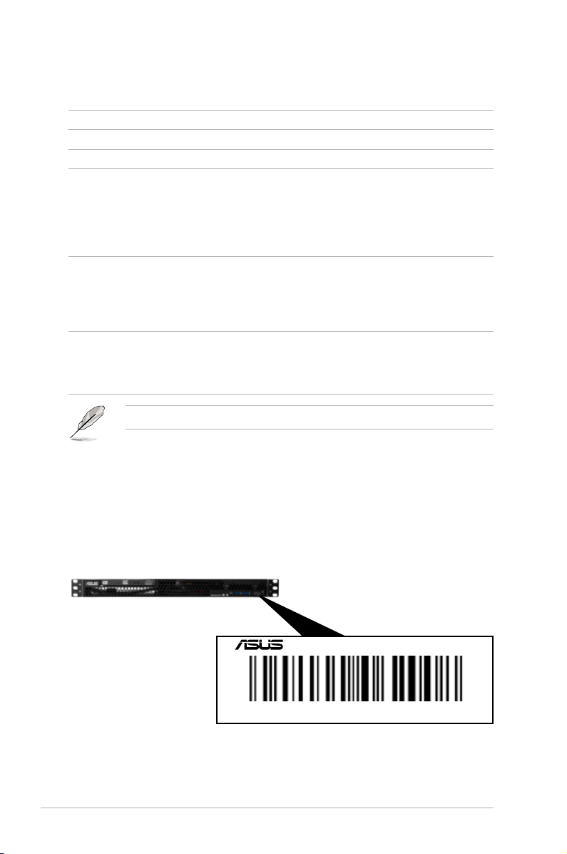
1.2 Serial number label
Before requesting support from the ASUS Technical Support team, take note of the product’s
14-character serial number as seen in the example xxS0xxxxxxxxxx below. With the correct
serial number of the product, ASUS Technical Support team members can quickly identify the
server model and provide a satisfactory solution to your technical issue.
1-2
RS100-E8-PI2
xxS0xxxxxxxxxx
Chapter 1: Product overview
Page 13
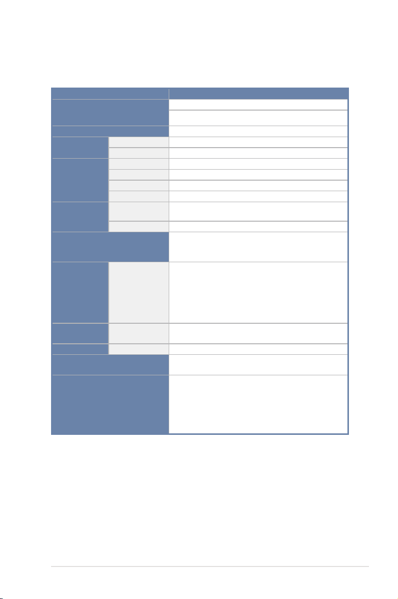
1.3 Systemspecications
The ASUS RS100-E8-PI2 is a 1U barebone server system featuring the ASUS P9D-M server
board.
Model Name RS100-E8/PI2
Processor / System Bus
Core Logic
ASUS Features
Memory
Expansion
Slots
Smart Fan
ASWM Enterprise
Total Slots
Capacity
Memory Type
Memory Size
Total PCI/PCI-X/
PCI-E Slots
Slot Type
Storage
I = internal
HDD Bays
A or S = hotswappable
1 x Socket LGA1150
Intel® Xeon® E3-1200 v3 Processor Family
Intel® C224 Chipset
√
√
4 (2 Channels)
Maximum up to 32GB
DDR3 1333 / 1600 Unbuffered DIMM with ECC
2GB, 4GB, 8GB
1
1 x PCI-E 3.0 x16 slot (x8 link) (Full-Height/HL)
4 x SATA3 6Gb/s
2 x SATA2 3Gb/s
Intel® RSTe supports software RAID 0,1
2 x Internal 3.5-inch SATA3 HDD bay
Or
1 x internal 3.5-inch SATA3 HDD bay +
1 x internal SSD bay* (Optional)
*Can support up to two 2.5-inch SSDs.
Networking
Graphic
LAN
VGA
Auxiliary Storage FDD / CD / DVD
Onboard I/O
(continued on the next page)
ASUS RS100-E8-PI2
2 x Intel® I210AT
1 x Mgmt LAN
Aspeed® AST2300 32MB
1 x Slim-type Optical Device Bay
(Options: No ODD / DVD-ROM / DVD-RW)
1 x External Serial Port
3 x RJ-45 ports (1 for ASMB7-iKVM)
4 x USB 3.0 ports (Front x 2, Rear x 2)
1 x VGA port
2 x USB 2.0 port (Rear x2)
1 x PS/2 keyboard/mouse port
1-3
Page 14

Windows® Server 2012 64-bit
Windows® 8 64-bit
Windows® Server 2008 Enterprise SP2 64-bit
Windows® Server 2008 Enterprise R2 SP1 64-bit
OS Support
RedHat® Enterprise Linux AS 5.8 / 6.2 / 6.3 U8 64-bit
CentOS 5.8 / 6.2 / 6.3 64-bit
Ubuntu 12.04 LTS 64-bit
*SupportedOSversionsaresubjecttochangewithout
notice
Anti-virus Software
Out of Band
Management
Solution
Remote
Hardware
Software
Net Weight Kg (CPU, DRAM &
HDD not included)
Dimensions (DD x WW x HH)
Power Supply
Power Rating
Optional anti-virus CD Pack
Optional ASMB7-iKVM for KVM-over-IP support
ASUS ASWM Enterprise
6.5 Kg
380mm x 430mm x 43.4mm
250W Single Power Supply
Input: 100-240Vac, 4A, 50-60Hz, Class I
Operation temperature: 10°C–40°C
Environment
Non-operating temperature: -40°C–70°C
Non-operation humidity: 20%–90% ( Non-
condensing)
*Specicationsaresubjecttochangewithoutnotice.
®
1-4
Chapter 1: Product overview
Page 15
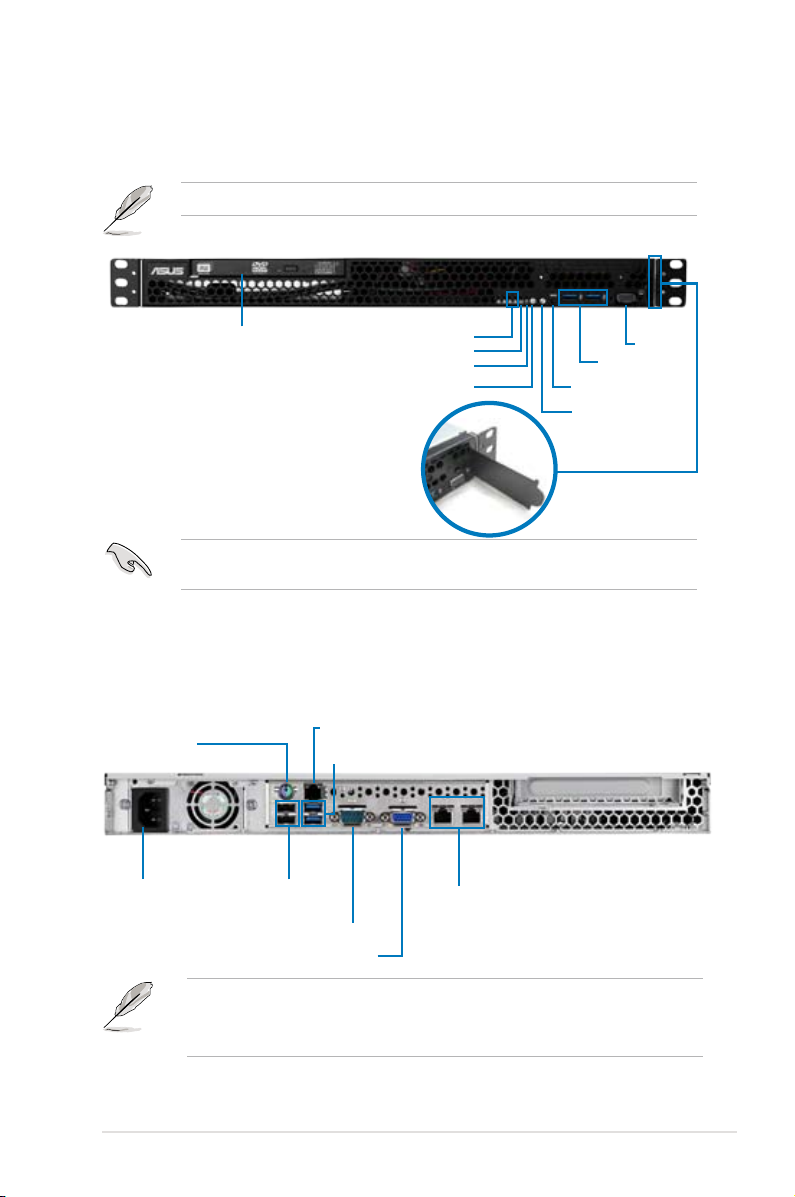
1.4 Front panel features
This barebone server has a simple yet stylish front panel with easily accessible features. The
power and reset buttons, LED indicators, optical drive, and two USB ports are located on the
front panel.
Refer to section 1.7.1 Front panel LEDs for the LED descriptions.
Optical drive (optional)
LAN1~2 LEDs
Message LED
HDD Access LED
Power button
VGA port
USB 3.0 ports
Reset button
LED location button
Asset tag
Turn off the system power and detach the power supply before removing or replacing any
system component.
1.5 Rear panel features
The rear panel has the AC power socket and access to any added expansion cards. The I/O
shield with openings for the rear panel connectors on the motherboard are also found in the
rear panel.
PS/2 mouse/keyboard
combo port
AC power socket USB 2.0 ports
LAN port 3*
USB 3.0 ports
LAN ports 1~2
• The ports for the PS/2 mouse/keyboard combo, USB 2.0 / USB 3.0, VGA, COM port,
and Gigabit LAN do not appear on the rear panel if the motherboard is not installed.
• *This port is for an ASUS ASMB7-iKVM controller card only.
ASUS RS100-E8-PI2
Serial port
VGA port
1-5
Page 16

1.6 Internal features
The barebone server includes the basic components as shown.
1
7
1. PCI Express x16 Riser Card (at x8 link)
2. System Fan (x2)
3. ASUS P9D-M Server board
4. Power Supply
5. Slim-type Optical Drive (Optional)
6. HDD Tray 1
7. HDD Tray 2 (partly hidden)
Turn off the system power and detach the power supply before removing or replacing any
system component.
5
3
2
4
6
1-6
This barebone server does not include a oppy disk drive. Connect a USB oppy disk drive
to any of the USB ports on the front or rear panel if you need to use a oppy disk.
*WARNING
HAZARDOUS MOVING PARTS
KEEP FINGERS AND OTHER BODY PARTS AWAY
Chapter 1: Product overview
Page 17
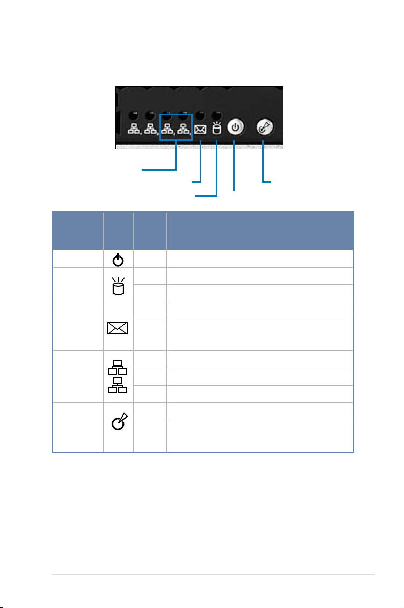
1.7 LED information
1
2
1.7.1 Front panel LEDs
LAN1~2 LED
Message LED
HDD Access LED
Location LED
Power LED
LED Icon
Power LED
HDD Activity
LED
Message
LED
LAN LEDs
Location LED
Display
status
Description
ON System power ON
OFF No activity
Blinking Read/write data activity from the HDD
OFF System is normal; indicates no incoming event
1. Without ASMB7-iKVM installed: CPU over-heated
ON
2. With ASMB7-iKVM installed: indicates a hardware
monitor event
OFF No LAN connection
Blinking LAN is transmitting or receiving data
ON LAN connection is present
ON Location switch is pressed.
OFF
Normal status.
(Press the location switch again to turn off.)
ASUS RS100-E8-PI2
1-7
Page 18
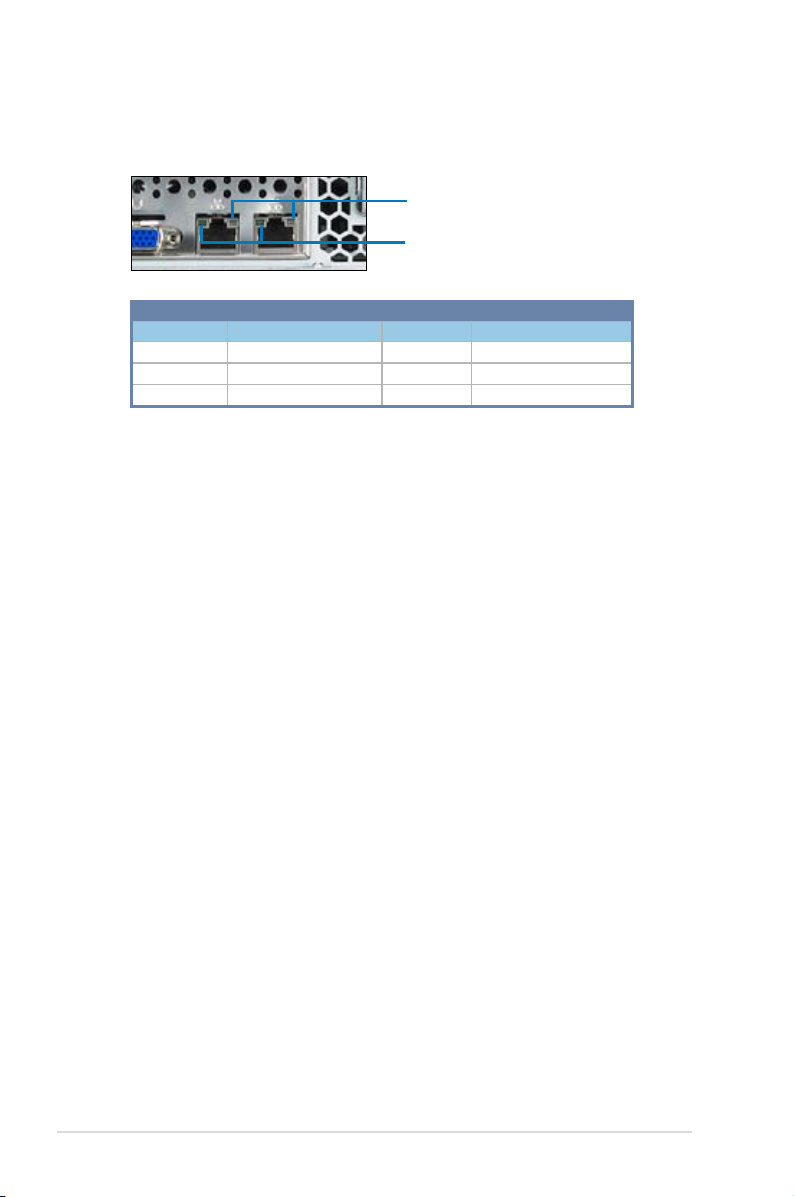
1.7.2 LAN (RJ-45) LEDs
SPEED LED
ACT/LINK LED
ACT/LINK LED SPEED LED
Status Description Status Description
OFF No link OFF 10 Mbps connection
GREEN Linked ORANGE 100 Mbps connection
BLINKING Data activity GREEN 1 Gbps connection
1-8
Chapter 1: Product overview
Page 19

Chapter 2
This chapter lists the hardware setup
procedures that you have to perform when
installing or removing system components.
Hardware setup
Page 20
2.1 Chassis cover
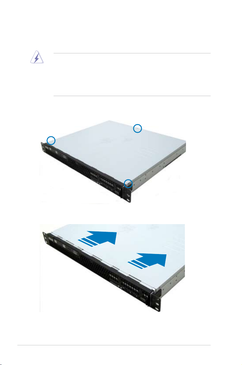
2.1.1 Removing the chassis cover
• Unplug the power cord before removing the chassis cover.
• Take extra care when removing the chassis cover. Keep your ngers away from
components inside the chassis that can cause injury, such as the CPU fan, rear fan,
and parts with sharp or protruding edges.
• The images of the barebone server shown in this section are for reference purposes
only and may not exactly match the model you purchased.
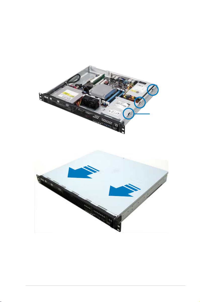
To remove the chassis cover:
1. Use a Phillips screwdriver to remove the three screws on the chassis cover.
2. Firmly hold the cover and slide it toward the rear panel for about half an inch until it is
disengaged from the chassis.
3. Lift the cover from the chassis.
2-2
Chapter 2: Hardware setup
Page 21
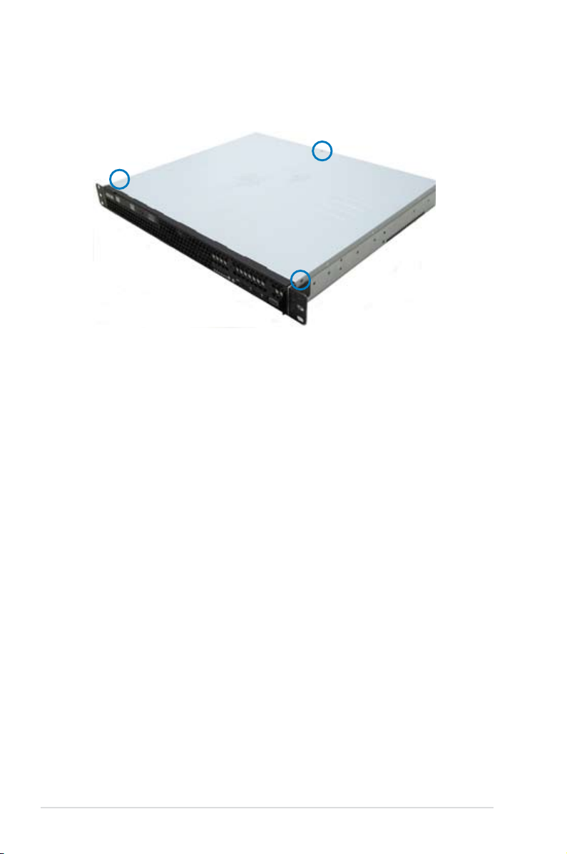
2.1.2 Reinstalling the chassis cover
To reinstall the chassis cover:
1. Position the cover on top of the chassis with the hooks aligned to the side tabs of the
chassis.
Side tabs
2. Slide the cover toward the front until it snaps in place.
ASUS RS100-E8-PI2
2-3
Page 22
3. Secure the cover with three screws.
2-4
Chapter 2: Hardware setup
Page 23
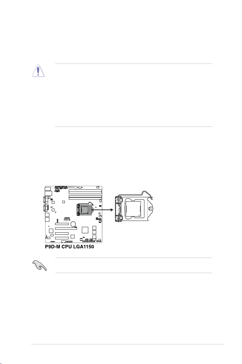
2.2 Central Processing Unit (CPU)
This server motherboard comes with a surface mount LGA1150 socket designed for the Intel®
Xeon® E3-1200 v3.
• Upon purchase of the motherboard, ensure that the PnP cap is on the socket and
the socket contacts are not bent. Contact your retailer immediately if the PnP cap
is missing, or if you see any damage to the PnP cap/socket contacts/motherboard
components. ASUS will shoulder the cost of repair only if the damage is shipment/
transit-related.
• Keep the PnP cap after installing the motherboard. ASUS will process Return
Merchandise Authorization (RMA) requests only if the motherboard comes with the
cap on the LGA1150 socket.
• The product warranty does not cover damage to the socket contacts resulting from
incorrect CPU installation/removal, or a lost/improper removal of the PnP cap.
2.2.1 Installing the CPU
To install the CPU:
1. Locate the CPU socket on the motherboard.
Before installing the CPU, ensure that the socket box is facing toward you and the load
lever is on your right.
ASUS RS100-E8-PI2
2-5
Page 24
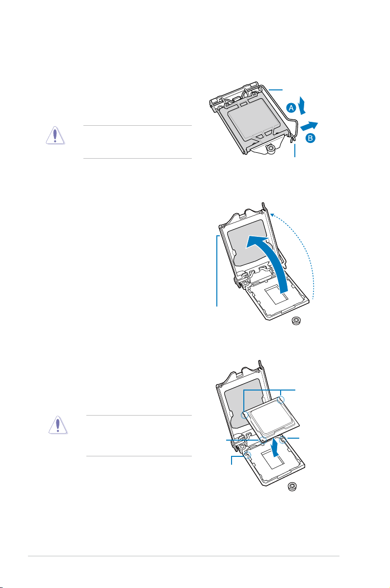
2. Press the load lever with your thumb
(A), then move it to the right (B) until it is
released from the retention tab.
Do not remove the PnP cap yet from
the CPU socket. Doing so may bend
the pins of the socket.
3. Lift the load lever until the load plate is
completely lifted.
4. Position the CPU above the socket,
ensuring that the gold triangle mark is
on the bottom-left corner of the socket,
then t the CPU notches to the socket's
alignment keys.
Load lever
Retention tab
Load plate
CPU notches
2-6
The CPU ts in only one orientation.
DO NOT force the CPU into the
socket to prevent bending the pins on
the socket and damaging the CPU.
Gold
triangle
mark
Alignment
Alignment
key
key
Chapter 2: Hardware setup
Page 25
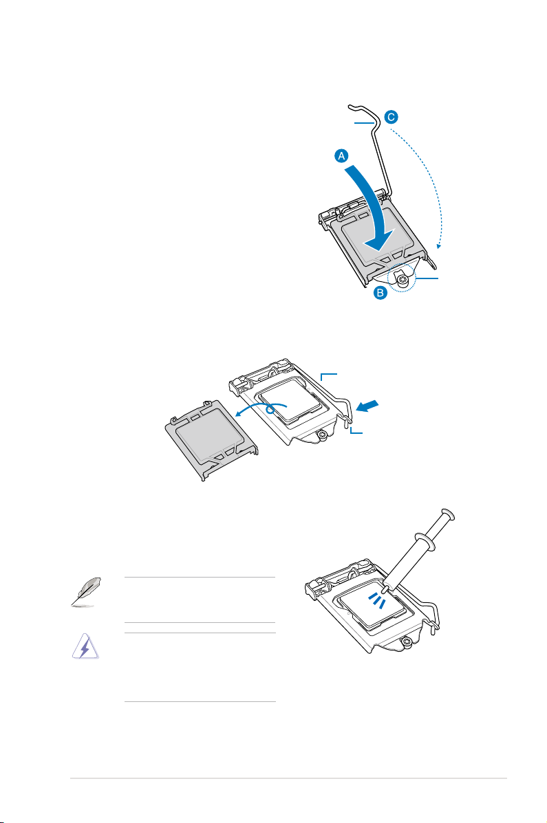
5. Close the load plate (A), ensuring that
the front edge of the load plate slides
under the retention lock (B) then push
Load lever
down the load lever (C).
Retention
lock
6. Insert the load lever under the retention tab to remove the PnP cap from the CPU
socket.
Load lever
Retention tab
7. Apply some Thermal Interface Material
to the exposed area of the CPU that
the heatsink will come in contact with,
ensuring that it is evenly spread in a thin
layer.
If the heatsink comes with pre-applied
Thermal Interface Material skip this
step.
The Thermal Interface Material is
toxic and inedible. DO NOT eat it. If
it gets into your eyes or touches your
skin, wash it off immediately and seek
professional medical help.
ASUS RS100-E8-PI2
2-7
Page 26
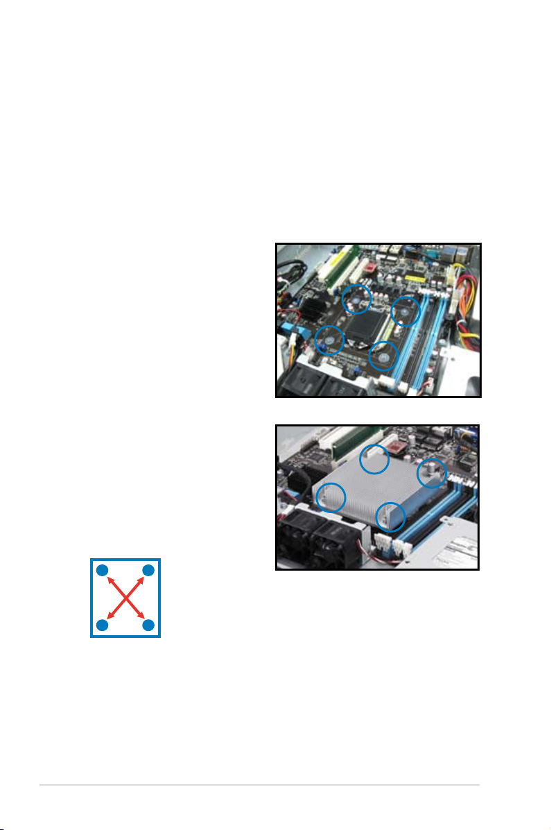
2.2.2 Installing the CPU heatsink
To install the CPU heatsink:
1. Remove the protection sticker from the
back of the CPU heatsink.
2. Place the heatsink on top of the installed
CPU, ensuring that the four fasteners
match the holes on the motherboard.
3. Using a Philips screwdriver, lightly screw
on the heatsink onto the motherboard
using all four screws. Once all four
screws are attached, tighten the four
heatsink screws in a diagonal sequence
until the heatsink is secure on the
motherboard.
2-8
A
B
B
A
Chapter 2: Hardware setup
Page 27
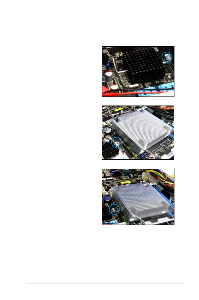
To install the airduct:
1. Locate and remove the screw for the
airduct from the motherboard.
2. Place the airduct over the heatsink. The
fastener on the airduct should align with
the screwhole on the motherboard.
3. Replace the screw and secure the
airduct onto the motherboard.
ASUS RS100-E8-PI2
2-9
Page 28
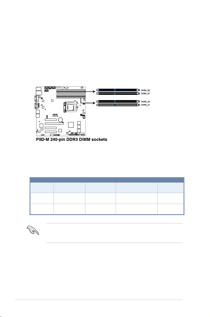
2.3 System memory
2.3.1 Overview
The motherboard comes with four Double Data Rate 3 (DDR3) Dual Inline Memory Modules
(DIMM) sockets.
A DDR3 module has the same physical dimensions as a DDR2 DIMM but is notched
differently to prevent installation on a DDR2 DIMM socket. DDR3 modules are developed for
better performance with less power consumption.
The gure illustrates the location of the DDR3 DIMM sockets:
2.3.2 MemoryCongurations
You may install 2 GB, 4 GB, and 8 GB Unbuffered with ECC DDR3 DIMMs into the DIMM
sockets using the memory congurations in this section.
2-10
DIMM Slot
Per Channel
2 1
2 2
• Always install DIMMs with the same CAS latency. For optimum compatibility, it is
• Start installing the DIMMs in slots A2 and B2 (Blue).
DIMM Populated
per Channel
recommended that you obtain memory modules from the same vendor.
UDIMM
DIMM Type Speed
Unbuffered
DDR3
Unbuffered
DDR3
1333/1600
1333/1600
Chapter 2: Hardware setup
Rank per
DIMM
Single Rank
Dual Rank
Single Rank
Dual Rank
Page 29
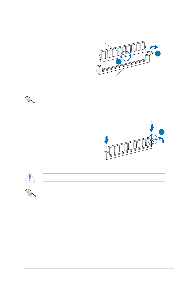
2.3.3 Installing a DIMM on a single clip DIMM socket
1. Unlock a DIMM socket by pressing
the retaining clip outward.
2. Align a DIMM on the socket such that
the notch on the DIMM matches the
DIMM slot key on the socket.
A DIMM is keyed with a notch so that it ts in only one direction. DO NOT force a DIMM into
a socket in the wrong direction to avoid damaging the DIMM.
3. Hold the DIMM on both ends then
insert the DIMM vertically into the
socket. Apply force to both ends of
the DIMM simultaneously until the
retaining clip snaps back into place
and the DIMM cannot be pushed in
any further to ensure proper seating
of the DIMM.
Always insert the DIMM into the socket vertically to prevent DIMM notch damage.
DIMM notch
DIMM slot key
1
2
Unlocked retaining clip
3
Locked Retaining Clip
• To install two or more DIMMs, refer to the user guide bundled in the motherboard
package.
• Refer to the user guide for the Qualied Vendor List (QVL) of the memory modules.
ASUS RS100-E8-PI2
2-11
Page 30
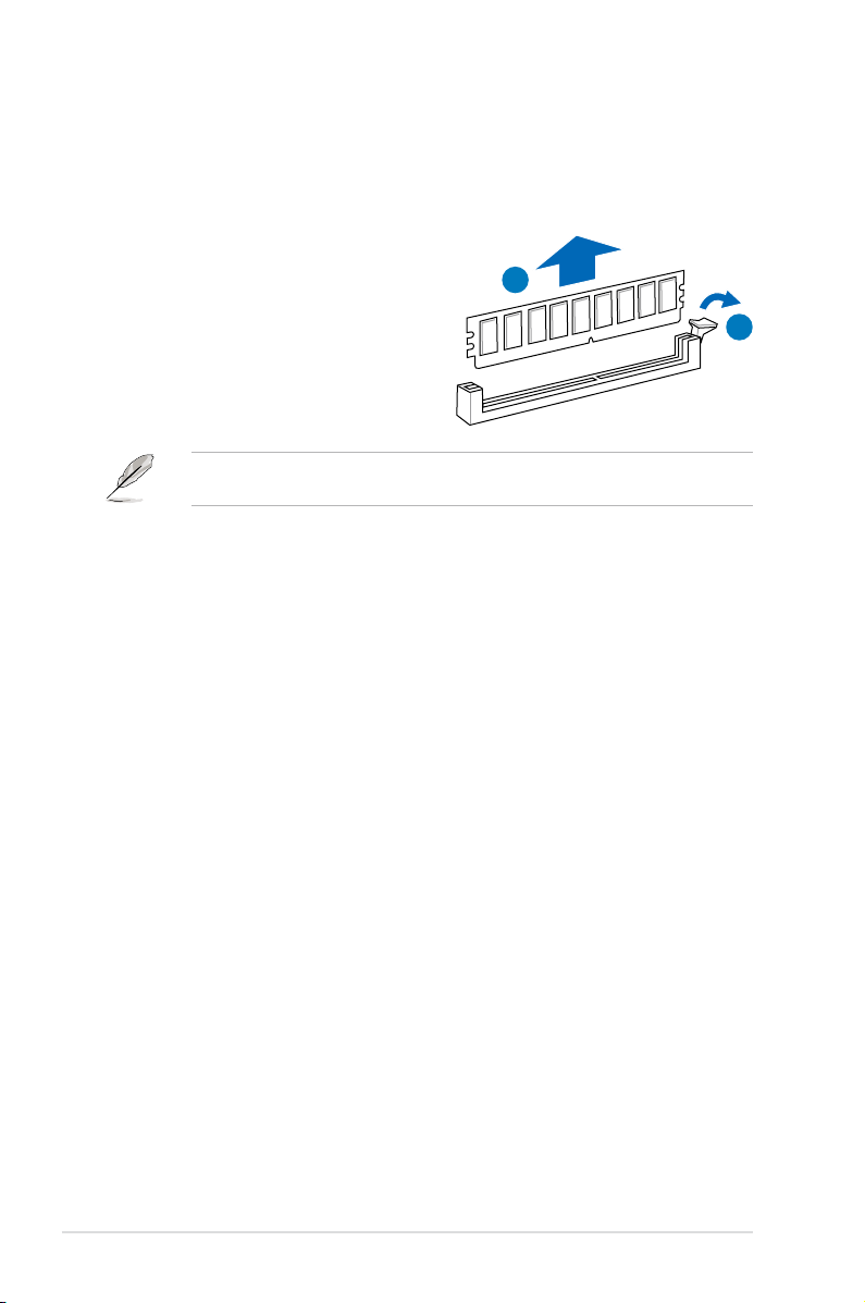
Removing a DIMM from a single clip DIMM socket
1. Press the retaining clip outward to
unlock the DIMM.
2. Remove the DIMM from the socket.
Support the DIMM lightly with your ngers when pressing the retaining clips. The DIMM
might get damaged when it pops out with extra force.
2
1
2-12
Chapter 2: Hardware setup
Page 31

2.4 Hard disk drives
The server chassis has two HDD bays for installing HDDs to the system. Both HDD bays can
support 3.5-inch Serial ATA HDD.
2.4.1 Installing a 3.5-inch Serial ATA HDD to HDD bay 1
To install a 3.5-inch Serial ATA HDD to HDD bay 1:
1. Locate the HDD bay 1 in the chassis.
2. Release the four screws that secures the HDD drive tray to the chassis and set aside.
3. Remove the HDD drive tray then set aside.
4. Prepare a 3.5-inch Serial ATA HDD
and the set of bundled screws.
5. Insert the 3.5-inch Serial ATA HDD into
the HDD drive tray and secure it using
the bundled set of screws (as shown).
Ensure that the 3.5-inch SATA HDD is
seated securely in place.
ASUS RS100-E8-PI2
HDD drive tray
HDD bay 1
2-13
Page 32

6. Connect the SATA signal cable and a
power from the power supply to the
3.5-inch HDD.
Use an L-type SATA connector to
connect the 3.5-inch SATA HDD to the
motherboard.
7. Place and orient the HDD tray and
3.5-inch SATA HDD assembly in such
a way that the SATA cable and power
connector is aligned towards the rear
(as shown).
8. Secure the 3.5-inch SATA HDD and
HDD drive tray assembly to the HDD
bay 1 using the screws removed in
step 2.
Ensure that the SSD drive tray is
seated securely in place.
2-14
Chapter 2: Hardware setup
Page 33

2.4.2 Installing 2.5-inch SSDs on HDD bay 1 (Optional)
To replace an installed 3.5-inch Serial ATA HDD with two 2.5-inch SSDs in HDD bay 1:
1 Locate the 3.5-inch Serial ATA (SATA) HDD and the HDD drive tray assembly in the
chassis.
Disconnect the SATA cable and the power cable from the 3.5-inch SATA HDD.
2.
Release the four screws that secure the HDD drive tray and 3.5-inch SATA HDD
3.
assembly to HDD bay 1 and set aside.
HDD drive tray
HDD bay 1
4.
Remove the HDD drive tray and 3.5-inch SATA HDD assembly.
5. Prepare the SSD drive tray.
6. Get one 2.5-inch SSD and orient it in
such a way that the SATA connector
of the 2.5-inch SSD is exposed as
shown.
Ensure that the screw holes on the
underside of the 2.5-inch SSD matches
the screw holes on the SSD drive tray.
7. Fasten the 2.5-inch SSD to the SSD
drive tray using four screws.
ASUS RS100-E8-PI2
SSD drive tray
2.5-inch SSD
2-15
Page 34

8. Repeat step 6 - 7 to install the other
2.5-inch SSD.
9. Prepare the SATA power cable and
the SATA signal cable bundled with
the SSD drive tray.
10. Get a SATA power cable and connect
it to the 2.5-inch SSD as shown.
Use the SATA power cable that
comes with the SSD drive tray as
an add-on accessory.
11. Get a SATA signal cable and connect
it to the 2.5-inch SSD as shown.
Connect the other end of the SATA
12.
signal cable to the SATA connector on
the motherboard.
SSD drive tray
2.5-inch SSD
SATA power cable
Use the SATA signal cable that
comes with the SSD drive tray as
an add-on accessory.
13. Connect the 4-pin power connector
of the power cable to the 4-pin power
connector from the power supply.
2-16
SATA signal cable
from the SSD power cable
from the power supply
4-pin power connector
Chapter 2: Hardware setup
Page 35

14. Align and orient the 2.5-inch SSD and
the SSD drive tray assembly into the
HDD bay 1 (as shown) matching the
four screw holes on the drive tray with
the four screw holes on the HDD bay.
15. Carefully place the 2.5-inch SSD and
the SSD drive tray assembly into HDD
bay 1.
Ensure that no cables or connectors
are out-of-place.
16. Secure the 2.5-inch SSD and SSD
drive tray assembly to the HDD bay 1
using the screws removed in step 3.
Ensure that the SSD drive tray is
seated securely in place.
ASUS RS100-E8-PI2
2-17
Page 36

2.4.3 Installing a hard disk drive to the HDD bay 2
To install a 3.5-inch Serial ATA HDD to HDD bay 2:
1. If you have an Optical Disc Drive (ODD) installed, remove it rst before installing a
3.5-inch Sertial ATA HDD to HDD bay 2.
To remove the ODD:
1.a Locate the ODD in the server chassis
ODD cable
HDD bay 2
.
2-18
Optical Disc DriveHDD drive tray
1.b Disconnect the SATA and power
cable on the ODD.
1.c Release the screw that secures
the ODD to the chassis and set
aside.
ODD cable
Chapter 2: Hardware setup
Page 37

1.d Remove the ODD as shown and
set aside.
2. Release the four screws that secures
the HDD drive tray to the chassis.
Set aside for later use.
3. Remove the HDD drive tray.
4. Get a 3.5-inch Serial ATA HDD and
the set of bundled screws.
Orient the 3.5-inch SATA HDD in
5.
such a way that the SATA and power
connector are exposed.
Secure the 3.5-inch Serial ATA HDD
to the HDD drive tray using the
bundled set of screws as shown.
6. Connect a SATA signal cable and a
power cable from the power supply to
the 3.5-inch SATA HDD.
Use an L-type SATA connector to
connect the 3.5-inch SATA HDD to
the motherboard.
ASUS RS100-E8-PI2
2-19
Page 38

7. Carefully place the 3.5-inch Serial ATA
HDD and HDD drive tray assembly into
the drive bay.
Ensure that no cables or connectors is
out-of-place.
8. Secure the HDD drive tray and the
3.5-inch SATA HDD assembly to the
HDD bay 2 using the four screws
removed in step 2
Ensure that screw holes on the HDD
drive tray and the 3.5-inch SATA HDD
assembly matches the screw holes on
the HDD bay 2 .
9. Get the ODD and slide it back into the
optical disc drive slot.
10. Secure the ODD and the HDD drive
tray to the HDD bay 2 using the screw
removed in step 1.c.
11. Connect the ODD signal cable and
power cable to the optical disk drive.
2-20
Chapter 2: Hardware setup
Page 39

2.5 Expansion card
This system comes with a riser card. You need to remove the riser card and the expansion
slot bracket if you want to install an expansion card.
Unplug the power cord before installing or removing an expansion card. Failure to do so
may cause severe damage to the motherboard and other system components!
2.5.1 Installing an expansion card
To install an expansion card:
1. Hold the riser card and pull it
upwards to detach it from the PCI
Express slot on the motherboard.
2. Remove the screw to release the
expansion card bracket from the
chassis.
3. Remove one more screw to release
the metal slot cover from the
expansion card bracket.
ASUS RS100-E8-PI2
2-21
Page 40

Separate the slot cover from the
expansion card bracket.
4. Insert the riser card into the PCI
Express slot until the golden
connectors completely t the slot
and the bracket aligns with the rear
panel.
5. Secure the expansion card to the
bracket with a screw.
6. Secure the assembly to the chassis
with a screw.
2-22
Chapter 2: Hardware setup
Page 41

2.5.2 Conguringanexpansioncard
After installing the expansion card, congure the software settings if needed.
1. Turn on the system and change any necessary BIOS settings. See
information on the BIOS setup.
2. Assign an IRQ to the card. Refer to the following table.
3. Install the software drivers for the expansion card.
Standard Interrupt assignments
IRQ Priority Standard function
0 1 System Timer
1 2 Keyboard Controller
2 - Programmable Interrupt
3* 11 Communications Port (COM2)
4* 12 Communications Port (COM1)
5* 13 --
6 14 Floppy Disk Controller
7* 15 -8 3 System CMOS/Real Time Clock
9* 4 ACPI Mode when used
10* 5 IRQ Holder for PCI Steering
11* 6 IRQ Holder for PCI Steering
12* 7 PS/2 Compatible Mouse Port
13 8 Numeric Data Processor
14* 9 Primary IDE Channel
15* 10 Secondary IDE Channel
* These IRQs are usually available for ISA or PCI devices.
Chapter 5 for
ASUS RS100-E8-PI2
2-23
Page 42

2.6 Cable connections
• The bundled system cables are set up before shipping. You do not need to disconnect
these cables unless you will remove pre-installed components to install additional
hardware components.
• Refer to
for detailed information on the connectors.
Chapter 4
1
2
3
5
7
Standard cables connected to the motherboard
1. 24-pin ATX power connector (from power supply to motherboard)
2. 8-pin ATX 12V power connector (from power supply to motherboard)
3. System fan and CPU fan connectors (from system fan to motherboard)
4. SATA conectors (system default; from motherboard to SATA devices)
5. USB 2.0 connector (from motherboard to front I/O board)
6. USB 3.0 connector (from motherboard to front I/O board)
7. System panel connectors (from motherboard to front I/O board)
3
3
3
3
4
6
2-24
Chapter 2: Hardware setup
Page 43

2.7 Removable/optional components
You may need to remove previously installed system components when installing or removing
system devices or you may need to install optional components into the system. This section
discusses how to remove/install the following components:
1. System fans
2. Optical disk drive (optional)
3. ASUS ASMB7-iKVM (optional)
Ensure that the system is turned off before removing any components.
2.7.1 Chassis fans
To install the system fans:
1. Locate the screw holes for the system
fans on the chassis. They are located
just next to the heatsink.
2. Position the chassis fans to match the
screw holes on the chassis. Secure
the fans onto the chassis using the
provided screws.
3. Connect the chassis fan cables to
the onboard fan connectors labeled
FRNT_FAN2, and FRNT_FAN3.
ASUS RS100-E8-PI2
2-25
Page 44

2.7.2 Optical disk drive (ODD)
To install the optical disk drive:
1. Slide in the optical disk drive into the
drive slot.
Optical disk drive slot
2. Align the screw hole of the ODD
bracket with the screw hole on the
chassis. Secure the ODD with a
screw.
3. Connect the ODD cable to the
optical disk drive.
2-26
Chapter 2: Hardware setup
Page 45

2.7.3 Installing ASMB7 series management card (optional)
Follow the steps below to install an optional ASMB7 series management card on your
motherboard.
1. Locate the ASMB7 header on the
motherboard.
2. Firmly t the ASMB7 management
card to the header. Do not force the
pins when connecting the card to
the motherboard header.
3. Insert the LAN cable plug to the
LAN port 3 (dedicated LAN) or
LAN port 1 (shared LAN) for server
management.
ASUS RS100-E8-PI2
LAN port 3
LAN port 1~2
2-27
Page 46

2-28
Chapter 2: Hardware setup
Page 47

Chapter 3
This chapter describes how to install the
rackmount rail kit to the barebone server.
Rackmount installation
2-
Page 48

3.1 Rackmount rail kit items
The rackmount rail kit contains two pairs of rails (one pair for each side of the server system),
six (6) pieces of inner rail screws, and two (2) pieces of rack screws.
Outer rails
Inner rails
Inner rail screwsRack screws
3.2 Attaching the rails to the rack
To attach the rack rails:
1. Attach the inner rail to the correspoding side of the chassis and secure with three inner
rail screws. Make sure the rail is oriented as shown.
3-2
Chapter 3: Rackmount installation
Page 49

2. Attach the second inner rail to the other side of the chassis and secure with three inner
rail screws.
3. Select one unit of space (1U) on the
rack w he re you wish to in stall the
server.
4. Place three (3) nuts on the front and
three at the back. Do the same to the
corresponding side of the rack.
Nuts
5. Adjust the length of the outer rail to
t the length of the rack cabinet, then
fasten the two screws.
6. Secure the outer rail with two screws
at t h e fron t a nd r e a r of the r ack
cabinet .
7. Find the corre sp onding 1U space
on the other side of the rack cabinet
then repeat steps 5 and 6 to attach
the other outer rail.
ASUS RS100-E8-PI2
3-3
Page 50

8. Firmly hold the server on both sides. Slide the latches on the inner rack rails to the
direction indicated below. Hold the latches, and insert the rear side of the server to the
front end of the outer rack rail.
Make sure that the inner rails are properly aligned with the outer rails.
3-4
Chapter 3: Rackmount installation
Page 51

9. Carefully push the server all the way to the back until the front panel ts the front end
of the rack.
10. Secure the server to the rack with one
ra ck s cre w a t on e si de. Sec ure the
other side as well.
Rack screw
ASUS RS100-E8-PI2
3-5
Page 52

3-6
Chapter 3: Rackmount installation
Page 53

Chapter 4
This chapter includes the motherboard layout
and brief description s of the jump er s and
internal connectors.
Motherboard Info
Page 54

4.1 Motherboard layout
4-2
Chapter 4: Motherboard information
Page 55

Layout contents
Onboard LEDs Page
1. Standby Power LED (SB_PWR1) 4-5
2. +5V Power LED (+5V_LED)
3. Location LED (LOC_LED1)
4. CPU Warning LED (ERR_CPU1)
5. Baseboard Management Controller LED (BMC_LED1)
4-5
4-5
4-6
4-6
Jumpers
1. Clear RTC RAM (CLRTC1)
2. VGA controller setting (3-pin VGA_SW1)
3. LAN controller setting (3-pin LAN_SW1, LAN_SW2,)
4. RAID conguration utility selection (3-pin RAID_SEL1)
5. Platform Environmental Control Interface Setting (3-pin PECI1)
6. ME rmware force recovery setting (3-pin ME_RCVR1)
7. VGA connector (16-1 pin VGA_HDR1)
Rear panel connectors Page
1. PS/2 keyboard/mouse port (purple/green) 4-10
2. RJ-45 port for iKVM
3. COM1 port
4. Video Graphics Adapter port
5. RJ-45 ports for LAN
6. LOCLED1
7. +5V_LED
8. Power-on Button
9. USB 2.0 ports 1 and 2
10. USB 3.0 ports 1 and 2
Page
4-7
4-8
4-8
4-8
4-9
4-9
4-9
4-10
4-10
4-10
4-10
4-10
4-10
4-10
4-10
4-10
ASUS RS100-E8-PI2
4-3
Page 56

Internal connectors
1. Serial ATA 6.0/3.0 Gbps connectors
2. Hard disk activity LED connector (4-pin HDLED1)
3. USB 2.0 connector
(10-1 pin USB78, 10-1 pin USB1011, A-Type USB9)
4. USB 3.0 connector (20-1 pin USB3_34)
5. Thermal sensor cable connectors (3-pin TR1)
6. CPU, front, and rear fan connectors
(4-pin FRNT_FAN1, REAR_FAN1, CPU_FAN1, FRNT_FAN2,
FRNT_FAN3)
7. Serial General Purpose Input/Output connector (6-1 pin SGPIO1)
8. Serial port connectors (10-1 pin COM2)
9. Trusted Platform Module connector (20-1 pin TPM1)
10. 4-pin power connector (4-pin PWR3)
11. ATX power connectors
(24-pin EATXPWR1, 8-pin EATX12V1)
12. System panel connector (20-1 pin PANEL1)
13. Auxiliary panel connector (20-2 pin AUX_PANEL1)
Page
4-11
4-11
4-12
4-12
4-14
4-13
4-14
4-15
4-15
4-16
4-16
4-17
4-18
4-4
Chapter 4: Motherboard information
Page 57

4.2 Onboard LEDs
1. Standby Power LED (SB_PWR1)
The motherboard comes with a standby power LED. The green LED lights up to indicate
that the system is ON, in sleep mode, or in soft-off mode. This is a reminder that you should
shut down the system and unplug the power cable before removing or plugging in any
motherboard component. The illustration below shows the location of the onboard LED.
2. +5V Power LED (+5V_LED1)
This LED lights up when the Power-on button is pressed and the system is on.
3 Locator LED (LOCLED1)
The Locator LED is a user-activated LED on the front of the server module that can be
remotely turned on or off. It is used to nd a specic server module within a chassis.
ASUS RS100-E8-PI2
4-5
Page 58

4. CPU Warning LED (ERR_CPU1)
The CPU warning LED lights up to indicate that a CPU error or failure has occurred.
5. Baseboard Management Controller LED (BMC_LED1)
The green heartbeat LED blinks per second to indicate that the ASMB7 is working
normally.
4-6
Chapter 4: Motherboard information
Page 59

4.3 Jumpers
1. Clear RTC RAM (3-pin CLRTC1)
This jumper allows you to clear the Real Time Clock (RTC) RAM in CMOS. You can clear
the CMOS memory of date, time, and system setup parameters by erasing the CMOS
RTC RAM data. The onboard button cell battery powers the RAM data in CMOS, which
include system setup information such as system passwords.
To erase the RTC RAM:
1. Turn OFF the computer and unplug the power cord.
2. Move the jumper cap from pins 1–2 (default) to pins 2–3. Keep the cap on pins 2–3
for about 5–10 seconds, then move the cap back to pins 1–2.
3. Plug the power cord and turn ON the computer.
4. Hold down the <Del> key during the boot process and enter BIOS setup to re-enter
data.
Except when clearing the RTC RAM, never remove the cap on CLRTC jumper default position.
Removing the cap will cause system boot failure!
If the steps above do not help, remove the onboard battery and move the jumper again to clear
the CMOS RTC RAM data. After the CMOS clearance, reinstall the battery.
ASUS RS100-E8-PI2
4-7
Page 60

2. VGA controller setting (3-pin VGA_SW1)
This jumper allows you to enable or disable the onboard VGA controller. Set to pins 1–2
to activate the VGA feature.
3. LAN controller setting (3-pin LAN_SW1, LAN_SW2)
These jumpers allows you to enable or disable the onboard Intel® I210AT Gigabit LAN
controllers. Set to pins 1-2 to activate the Gigabit LAN feature.
4. RAIDcongurationutilityselection(3-pinRAID_SEL1)
This jumper allows you to select the RAID conguration utility for creating disk arrays.
Place the jumper caps over pins 1–2 if you want to use a Third-Party Setup Utility
(default). Otherwise, place the jumper caps to pins 2–3 to use the Intel® Rapid Storage
Technology.
4-8
Chapter 4: Motherboard information
Page 61

5. Platform Enviromental Control Interface Setting (3-pin PECI1)
When ASMB7-iKVM is installed, set to pins 2-3 for correct sensor information of the
Platform Environmental Control Interface (PECI). Set to pins 1-2 if ASMB7-iKVM is not
installed.
6. MErmwareforcerecoverysetting(3-pinME_RCVR1)
This jumper allows you to force Intel Management Engine (ME) boot from recovery
mode when ME become corrupted.
7. VGA connector (16-1 pin VGA_HDR1)
This connector supports VGA High Dynamic-Range interface HDR1.
ASUS RS100-E8-PI2
4-9
Page 62

4.4 Connectors
4.4.1 Rear panel connectors
1. PS/2 keyboard/mouse port (purple/green). This port is for a PS/2 keyboard or
mouse.
2. RJ-45 port for iKVM.
management card.
3. Serial port.
specication.
4. Video Graphics Adapter port.
devices.
5. RJ-45 ports for LAN. These ports allows Gigabit connection to a Local Area Network (LAN)
through a network hub. Refer to the table below for the LAN port LED indications.
6. +5V_LED.
on.
7. LOCLED1.
that can be remotely turned on or off. It is used to nd a specic server module within a
chassis.
8. Power-on Button.
9. USB 2.0 ports 1 and 2.
for connecting USB 2.0 devices.
10. USB 3.0 ports 1 and 2. These two 4-pin USB ports are available for connecting USB 3.0
devices.
This port connects a modem, or other devices that conform with serial
This LED lights up when the Power-on button is pressed and the system is
The Locate LED is a user-activated LED on the front of the server module
This RJ-45 port functions only when you install an ASMB7
This port is for a VGA monitor or other VGA-compatible
Press this button to power on the system.
These two 4-pin Universal Serial Bus (USB) ports are available
LAN port LED indications
Activity/Link LED Speed LED
Status Description Status Description
OFF No link OFF 10 Mbps connection
GREEN Linked ORANGE 100 Mbps connection
BLINKING Data activity GREEN 1 Gbps connection
4-10
SPEED LEDACT/LINK
LED
LAN port
Chapter 4: Motherboard information
Page 63

4.4.2 Internal connectors
1. Serial ATA 6.0/3.0 Gbps connectors
• 7-pin SATA 6Gbps_1-4 connector [Light Blue])
• 7-pin SATA 3Gbps_5-6 connector [Black])
Supported by the Intel® C224 chipset, these connectors support up to 6Gbps of data
transfer rate to Serial ATA hard disk drives.
If you installed Serial ATA hard disk drives, you can create a RAID 0, RAID 1, RAID 10,
or RAID 5 conguration.
The actual data transfer rate depends on the speed of the Serial ATA hard disks
installed.
2. Hard disk activity LED connector (4-pin HDLED1)
This LED connector is for the storage add-on card cable connected to the SATA or SAS
add-on card. The read or write activities of any device connected to the SATA or SAS
add-on card causes the front panel LED to light up.
ASUS RS100-E8-PI2
4-11
Page 64

3. USB 2.0 connector (10-1 pin USB78, A-Type USB9)
These connectors are for USB 2.0 ports. Connect the USB module cables to the USB78
connector. These USB connectors comply with USB 2.0 specications and supports up
to 480 Mbps connection speed.
4. USB 3.0 connector (20-1 pin USB3_34)
These connectors allow you to connect a USB 3.0 module for additional USB 3.0 front
or rear panel ports. With an installed USB 3.0 module, you can enjoy all the benets of
USB 3.0 including faster data transfer speeds of up to 5Gbps, faster charging time for
USB-chargeable devices, optimized power efciency, and backward compatibility with
USB 2.0.
4-12
Chapter 4: Motherboard information
Page 65

5. CPU, front, and rear fan connectors
(4-pin FRNT_FAN1, REAR_FAN1, CPU_FAN1, FRNT_FAN2, FRNT_FAN3)
The fan connectors support cooling fans. Connect the fan cables to the fan connectors
on the motherboard, ensuring that the black wire of each cable matches the ground pin
of the connector.
• DO NOT forget to connect the fan cables to the fan connectors. Insufcient air ow inside
the system may damage the motherboard components.
• These are not jumpers! DO NOT place jumper caps on the fan connectors!
• All fans feature the ASUS Smart Fan technology.
ASUS RS100-E8-PI2
4-13
Page 66

6. Thermal sensor cable connectors (3-pin TR1)
This connector allows you to connect a Thermal sensor cable that is used for temperature
monitoring. Connect the Thermal sensor cable to the connector and place its probe to the
device that you want to check the temperature.
7. Serial General Purpose Input/Output connector (6-1 pin SGPIO1)
The SGPIO 1 connectors are used for the Intel® Rapid Storage Technology Enterprise
SGPIO interface that manages LED pattern generation, device information, and general
purpose data.
4-14
Chapter 4: Motherboard information
Page 67

8. Serial port connectors (10-1 pin COM2)
These connectors are for the serial COM2 port. Connect the serial port module cable
to one of these connectors, then install the module to a slot opening at the back of the
system chassis.
9. Trusted Platform Module connector (20-1 pin TPM1)
This connector supports a Trusted Platform Module (TPM) system, which can securely
store keys, digital certicates, passwords, and data. A TPM system also helps enhance
network security, protects digital identities, and ensures platform integrity.
ASUS RS100-E8-PI2
4-15
Page 68

10. 4-pin power connector (4-pin PWR3)
This 4-pin connector provides 5V to an installed SATA DOM (Disk on Module). You can also use
this 4-pin connector to connect to the PSU to increase power by 12V.
11. ATX power connectors (24-pin EATXPWR1, 8-pin EATX12V1)
These connectors are for the ATX power supply plugs. The power supply plugs are
designed to t these connectors in only one orientation. Find the proper orientation and
push down rmly until the connectors completely t.
• Do not forget to connect the 24-pin and 8-pin power plugs or the system will not boot
up.
• Use of a power supply unit (PSU) with a higher power output is recommended when
conguring a system with more power-consuming devices. The system may become
unstable or may not boot up if power is inadequate.
• This motherboard supports ATX2.0 PSU or later version.
• Ensure that your PSU can provide at least the minimum power required by your
system.
4-16
Chapter 4: Motherboard information
Page 69

12. System panel connector (20-1 pin PANEL1)
This connector supports several chassis-mounted functions.
1. System power LED (3-pin PLED)
This 3-pin connector is for the system power LED. Connect the chassis power LED
cable to this connector. The system power LED lights up when you turn on the
system power, and blinks when the system is in sleep mode.
2. Message LED (2-pin MLED)
This 2-pin connector is for the message LED cable that connects to the front message
LED. The message LED indicates any detected abnormal activity in the hardware.
3. System warning speaker (4-pin SPEAKER)
This 4-pin connector is for the chassis-mounted system warning speaker. The
speaker allows you to hear system beeps and warnings.
4. Hard disk drive activity LED (2-pin +HDLED)
This 2-pin connector is for the HDD Activity LED. Connect the HDD Activity LED
cable to this connector. The IDE LED lights up or ashes when data is read from
or written to the HDD.
5. Power button/soft-off button (2-pin PWRSW)
This connector is for the system power button. Pressing the power button turns
the system on or puts the system in sleep or soft-off mode depending on the BIOS
settings. Pressing the power switch for more than four seconds while the system is
ON turns the system OFF.
6. Reset button (2-pin RESET)
This 2-pin connector is for the chassis-mounted reset button. Press this button to
reboot the system without turning off the system power.
ASUS RS100-E8-PI2
4-17
Page 70

13. Auxiliary panel connector (20-2 pin AUX_PANEL1)
This connector is for additional front panel features including front panel SMB, Locator
LED and switch, chassis intrusion, and LAN LEDs.
1. Front panel SMB (6-1 pin FPSMB)
These leads connect to the front panel SMBus cable.
2. LAN activity LED (2-pin LAN1LINK and 2-pin LAN2LINK)
These leads are for Gigabit LAN activity LEDs on the front panel.
3. Chassis intrusion (4-1 pin AUX_CHASSIS)
These leads are for the intrusion detection feature for chassis with an intrusion
sensor or microswitch. When you remove any chassis component, the sensor
triggers and sends a high-level signal to these leads to record a chassis intrusion
event. The default setting is short CASEOPEN and GND pin by jumper cap to
disable the function.
4. Locator LED (2-pin AUX_LOCLED1 and 2-pin AUX_LOCLED2)
These leads are for the Locator LED1 and LED2 on the front panel. Connect the
Locator LED cables to these 2-pin connectors. The LEDs will light up when the
Locator button is pressed.
4-18
5. Locator Button/Switch (2-pin AUX_BMCLOCBNT)
These leads are for the locator button on the front panel. This button queries the
state of the system locator.
Chapter 4: Motherboard information
Page 71

Chapter 5
This chapter tells how to change the system
settings through the BIOS Setup menus.
Detailed descriptions of the BIOS parameters
are also provided.
BIOS setup
Page 72

5.1 Managing and updating your BIOS
The following utilities allow you to manage and update the motherboard Basic Input/Output
System (BIOS) setup:
1.
ASUS CrashFree BIOS 3
To recover the BIOS using a bootable USB ash disk drive when the BIOS le fails or
gets corrupted.)
2.
ASUS EasyFlash Utility
Updates the BIOS using a USB ash disk.
3.
BUPDATER utility
Updates the BIOS in DOS mode using a bootable USB ash disk drive.
Refer to the corresponding sections for details on these utilities.
Save a copy of the original motherboard BIOS le to a bootable USB ash disk drive in
case you need to restore the BIOS in the future. Copy the original motherboard BIOS using
the BUPDATER utility.
5.1.1 ASUS CrashFree BIOS 3 utility
The ASUS CrashFree BIOS 3 is an auto recovery tool that allows you to restore the BIOS le
when it fails or gets corrupted during the updating process. You can update a corrupted BIOS
le using a USB ash drive that contains the updated BIOS le.
Prepare a USB ash drive containing the updated motherboard BIOS before using this
utility.
RecoveringtheBIOSfromaUSBashdrive
To recover the BIOS from a USB ash drive:
1. Insert the USB ash drive with the original or updated BIOS le to one USB port on the
system.
2. The utility will automatically recover the BIOS. It resets the system when the BIOS
recovery nished.
.
.
5-2
DO NOT shut down or reset the system while recovering the BIOS! Doing so would cause
system boot failure!
The recovered BIOS may not be the latest BIOS version for this motherboard. Visit the
ASUS website at www.asus.com to download the latest BIOS le.
Chapter 5: BIOS setup
Page 73

5.1.2 ASUS Easy Flash Utility
The ASUS Easy Flash Utility feature allows you to update the BIOS using a USB ash disk
without having to use a DOS-based utility.
Download the latest BIOS from the ASUS website at www.asus.com before using this utility.
The succeeding BIOS screens are for reference only. The actual BIOS screen displays may
not be the same as shown.
To update the BIOS using Easy Flash Utility:
1. Insert the USB ash disk that contains the latest BIOS le to the USB port.
2. Enter the BIOS setup program. Go to the
press <Enter> to enable it.
ASUSTek. Easy Flash Utility
Current Platform
Platform : P9D-M
Version : 0051
Build Date :11/26/2012
FS0
[Up/Down/Left/Right]:Switch [Enter]:Choose [q]:Exit
System Volume Information <DIR>
P9D-M Bios
P9D-E-4L Bios <DIR>
Windows <DIR>
Tool menu to select ASUS EzFlash Utility and
New Platform
Platform : P9D-M
Version : 0060
Build Date :03/03/2013
<DIR>
3. Press <Tab> to switch to the Drive eld.
4. Press the Up/Down arrow keys to nd the USB ash disk that contains the latest BIOS
then press <Enter>.
5. Press <Tab> to switch to the
Folder Info eld.
6. Press the Up/Down arrow keys to nd the BIOS le then press <Enter>.
7. Reboot the system when the update process is done.
ASUS RS100-E8-PI2
5-3
Page 74

• This feature supports USB ash disks formatted using FAT 32/16 on a single partition
only.
• DO NOT shut down or reset the system while updating the BIOS to prevent system boot
failure!
Load the BIOS default settings to ensure system compatibility and stability. Press <F5> and
select Yes to load the BIOS default settings.
5.1.3 BUPDATER utility
The succeeding BIOS screens are for reference only. The actual BIOS screen displays may
not be the same as shown.
The BUPDATER utility allows you to update the BIOS le in a DOS environment using a
bootable USB ash disk drive with the updated BIOS le.
UpdatingtheBIOSle
To update the BIOS le using the BUPDATER utility:
1. Visit the ASUS website at
motherboard. Save the BIOS le to a bootable USB ash disk drive.
2. Download the BUPDATER utility (BUPDATER.exe) from the ASUS support website at
support.asus.com to the bootable USB ash disk drive you created earlier.
3. Boot the system in DOS mode, then at the prompt, type:
BUPDATER /i[lename].CAP
where [lename] is the latest or the original BIOS le on the bootable USB ash disk
drive, then press <Enter>.
www.asus.com and download the latest BIOS le for the
5-4
A:\>BUPDATER /i[le name]CAP
Chapter 5: BIOS setup
Page 75

The utility veries the le, then starts updating the BIOS le.
FLASH TYPE: MXIC 25L1605A
PATH:
Writing BIOS:
ASUSTek BIOS Update for DOS V1.06 (09/08/04)
Current ROM Update ROM
BOARD: P9D-M
VER: 0202
DATE: 12/01/2012
WARNING! Do not turn off power during ash BIOS
Note
BOARD: P9D-M
VER: 0212
DATE: 03/09/2013
DO NOT shut down or reset the system while updating the BIOS to prevent system boot
failure!
The utility returns to the DOS prompt after the BIOS update process is completed.
4. Reboot the system from the hard disk drive.
The BIOS update is nished! Please restart your system.
C:\>
ASUS RS100-E8-PI2
5-5
Page 76

5.2 BIOS setup program
This motherboard supports a programmable rmware chip that you can update using the
provided utility described in section
5.1 Managing and updating your BIOS
Use the BIOS Setup program when you are installing a motherboard, reconfiguring your
system, or prompted to “Run Setup.” This section explains how to congure your system
using this utility.
Even if you are not prompted to use the Setup program, you can change the conguration of
your computer in the future. For example, you can enable the security password feature or
change the power management settings. This requires you to recongure your system using
the BIOS Setup program so that the computer can recognize these changes and record them
in the CMOS RAM of the rmware chip.
The firmware chip on the motherboard stores the Setup utility. When you start up the
computer, the system provides you with the opportunity to run this program. Press <Del>
during the Power-On Self-Test (POST) to enter the Setup utility; otherwise, POST continues
with its test routines.
If you wish to enter Setup after POST, restart the system by pressing <Ctrl>+<Alt>+<Del>,
or by pressing the reset button on the system chassis. You can also restart by turning the
system off then back on. Do this last option only if the rst two failed.
The Setup program is designed to make it as easy to use as possible. Being a menu-driven
program, it lets you scroll through the various sub-menus and make your selections from the
available options using the navigation keys.
• The default BIOS settings for this motherboard apply for most conditions to ensure
optimum performance. If the system becomes unstable after changing any BIOS
settings, load the default settings to ensure system compatibility and stability. Press
<F5> and select
• The BIOS setup screens shown in this section are for reference purposes only, and
may not exactly match what you see on your screen.
• Visit the ASUS website (
motherboard.
to load the BIOS default settings.
Yes
www.asus.com) to download the latest BIOS file for this
.
5-6
Chapter 5: BIOS setup
Page 77

5.2.1 BIOS menu screen
Menu bar CongurationeldsMenu items
Aptio Setup Utility - Copyright (C) 2013 American Megatrends, Inc.
Main Advanced Event Logs Boot Monitor Security Tool Exit
BIOS Information
BIOS Vendor American Megatrends
BIOS Version 4.6.5.4
Compliancy UEFI 2.3.1; PI 1.2
BIOS Version 0212 x64
Build Date 3/20/2013
System Date [Mon 01/06/2013]
System Time [15:07:28]
Version 2.15.1234. Copyright (C) 2013 American Megatrends, Inc.
Set the Date, Use Tab to
switch between Data elements.
General help
Select Screen
→←:
Select Item
↑↓:
Enter: Select Item
+/-: Change Opt.
F1: General Help
F2: Previous Values
F5: Optimized Defaults
F10: Save & Exit
ESC: Exit
Navigation keys
4.2.2 Menu bar
The menu bar on top of the screen has the following main items:
Main
Advanced
Event Logs
Boot
Monitor
For changing the basic system conguration
For changing the advanced system settings
For changing the event log settings
For changing the system boot conguration
For di sp la ying the system te mp er ature, powe r status, a nd
changing the fan settings
Security
Tool
Exit
For changing the security settings
For conguring options for special functions
For selecting the exit options
To select an item on the menu bar, press the right or left arrow key on the keyboard until the
desired item is highlighted.
ASUS RS100-E8-PI2
5-7
Page 78

5.2.3 Menu items
The highlighted item on the menu bar displays the specic items for that menu. For example,
selecting
Monitor, Security, Tool, and Exit) on the menu bar have their respective menu items.
shows the Main menu items. The other items (Advanced, Event Logs, Boot,
Main
5.2.4 Submenu items
A solid triangle before each item on any menu screen means that the item has a submenu. To
display the submenu, select the item and press <Enter>.
Aptio Setup Utility - Copyright (C) 2012 American Megatrends, Inc.
Main Advanced Event Logs Boot Monitor Security Tool Exit
PCI, PCI-X and PCI Express
PCI Subsystem Settings
ACPI Settings
Trusted Computing
PCI, PCI-X and PCI Express
Settings.
Settings.
5.2.5 Navigation keys
At the bottom right corner of a menu screen are the navigation keys for the BIOS setup
program. Use the navigation keys to select items in the menu and change the settings.
5.2.6 General help
At the top right corner of the menu screen is a brief description of the selected item.
5.2.7 Congurationelds
These elds show the values for the menu items. If an item is user-congurable, you can
change the value of the eld opposite the item. You cannot select an item that is not usercongurable. A congurable eld is enclosed in brackets, and is highlighted when selected. To
change the value of a eld, select it and press <Enter> to display a list of options.
5.2.8 Pop-up window
Select a menu item and press <Enter> to display a pop-up window with the conguration
options for that item.
5.2.9 Scroll bar
A scroll bar appears on the right side of a menu screen when there are items that do not t on
the screen. Press the Up/Down arrow keys or <Page Up> /<Page Down> keys to display the
other items on the screen.
5-8
Chapter 5: BIOS setup
Page 79

5.3 Main menu
When you enter the BIOS Setup program, the Main menu screen appears. The Main menu
provides you an overview of basic system information, and allows you to set the system date
and time.
Aptio Setup Utility - Copyright (C) 2012 American Megatrends, Inc.
Main Advanced Event Logs Boot Monitor Security Tool Exit
BIOS InformationBIOS Vendor American Megatrends
BIOS Version 4.6.5.4
Compliancy UEFI 2.3.1; PI 1.2
BIOS Version 0212 x64
Build Date 03/26/2013
System Date [Mon 3/26/2013]
System Time [15:07:28]
5.3.1 System Date
Allows you to set the system date to
Where:
Day = Day of the week
mm = month (numeric value)
dd = day (numeric value)
yyyy = year (numeric value)
[Day mm/dd/yyyy]
5.3.2 System Time
Allows you to set the system time to
[hh/mm/ss]
Where:
hh = hour (numeric value)
mm = minutes (numeric value)
ss = seconds (numeric value)
.
Set the Date, Use Tab to
s w i t c h b e t w e e n D a t a
elements.
.
ASUS RS100-E8-PI2
5-9
Page 80

5.4 Advanced menu
The Advanced menu items allow you to change the settings for the CPU and other hardware
components.
Take caution when changing the settings of the Advanced menu items. Incorrect eld values
can cause the system to malfunction.
Aptio Setup Utility - Copyright (C) 2012 American Megatrends, Inc.
Aptio Setup Utility - Copyright (C) 2013 American Megatrends, Inc.
Main Advanced Event Logs Boot Monitor Security Tool Exit
CPU Conguration
PCI Subsystem Settings
ACPI Settings
PCH-IO Conguration
Trusted Computing
SATA Conguration
WHEA Conguration
CPU Conguration
Systems Agent (SA) Conguration
PCH-IO Conguration
PCI Subsystem Settings
SATA Conguration
Systems Agent (SA) Conguration
USB Conguration
USB Conguration
TPM
NCT6779D Super IO Conguration
Intel Server Platforms Services
ACPI Settings
Onboard LAN Conguration
WHEA Conguration
MIO Card Conguration
Serial Port Console Redirection
NCT6779D Super IO Conguration
APM
Intel Server Platform Services
Network Stack
Intel RC Drivers Version Details
Onboard LAN Conguration
Serial Port Console Redirection
Runtime Error Logging
APM
Network Stack
Intel RC Drivers Version Detail
PCI, PCI-X and PCI Express
P C I , P C I - X a n d P C I
Settings.
Express Settings.
5-10
Chapter 5: BIOS setup
Page 81

5.4.1 CPUConguration
The items in this menu show CPU-related information that the BIOS automatically detects.
Some items may not appear if your CPU does not support the feature.
Aptio Setup Utility - Copyright (C) 2013 American Megatrends, Inc.
Advanced
CPU Conguration
Genuine Intel (R) CPU 0000 @ 2.50GHz
CPU Signature 306c2
Microcode Patch ffff0006
Max CPU Speed 2500 MHz
Min CPU Speed 800 MHz
Processor Cores 4
Intel HT Technology Supported
Intel VT-x Technology Supported
Intel SMX Technology Supported
64-bit Supported
EIST Technology Supported
CPU C3 State Supported
CPU C6 State Supported
CPU C7 State Supported
L1 Data Cache 32 kB x 4
L1 Code Cache 32 kB x 4
L2 Cache 256 kB x 4
L3 Cache 8192 kB
Version 2.15.1234. Copyright (C) 2013 American Megatrends, Inc.
Navigate to the second page of the screen to see all of the items in this menu by pressing the
Up or Down arrow keys.
To quickly go to the last item of the second page, press the Page Down button. Press the
Page Up button to go back to the rst item in the rst page.
Aptio Setup Utility - Copyright (C) 2013 American Megatrends, Inc.
Advanced
Hyper-threading [Enabled]
Active Processor Cores [All]
Overclocking lock [Disabled]
Execute Disable Bit [Enabled]
Intel Virtualization Technology [Enabled]
Hardware Prefetcher [Enabled]
Adjacent Cache Line Prefetch [Enabled]
CPU AES [Enabled]
Boot performance mode [Turbo Performance]
EIST [Enabled]
Turbo Mode [Enabled]
Energy Performance [Performance]
CPU C states [Enabled]
Enhanced C1 state [Enabled]
CPU C3 Report [Enabled]
CPU C6 report [Enabled]
CPU C7 report [CPU C7s]
C1 state auto demotion [Enabled]
C3 state auto demotion [Enabled]
Package C State demotion [Disabled]
C1 state auto undemotion [Enabled]
C3 state auto undemotion [Enabled]
Package C State undemotion[Disabled]
C state Pre-Wake [Enabled]
CFG lock [Enabled]
Package C State limit [AUTO]
LakeTiny Feature [Disabled]
Intel TXT (LT) Support [Disabled]
ACPI T State [Enabled]
Version 2.15.1234. Copyright (C) 2013 American Megatrends, Inc.
Enabled for WIndows XP and
Linux (OS optim ized f or
Enabled for Windows XP and
Hyper-Threading Technology)
Linux (OS optimized for
and Disabled for other OS
Hyper-Threading Technology)
(OS not optimized for Hyper-
and Disabled for other OS
Th r ead i ng T ech n ol o gy ) .
(OS not optimized for Hyper-
Wh en Di sabled o nl y o ne
Threading Technology).
thread per enabled core is
When Disabled only one thread
enabled.
per enabled core is enabled.
→←: Select Screen
↑↓: Select Item
Enter: Select Item
+/-: Change Opt.
→←: Select Screen
↑↓: Select Item
Enabled for Windows XP and
Enter: Select Item
Linux (OS optimized for
+/-: Change Opt.
Hyper-Threading Technology)
F1: General Help
and Disabled for other OS
F2: Previous Values
(OS not optimized for Hyper-
F5: Optimized Defaults
Threading Technology).
F10: Save & Exit
When Disabled only one thread
ESC: Exit
per enabled core is enabled.
ASUS RS100-E8-PI2
5-11
Page 82

Hyper-threading [Enabled]
Allows you to enable or disable the Intel® Hyper-Threading Technology. Configuration
options: [Enabled] [Disabled]
Active Processor Cores [All]
Allows you to choose the number of CPU cores to activate in each processor package.
Conguration options: [All] [1] [2] [3]
Overclocking lock [Disabled]
Allows you to enable or disable the overclocking lock. Configuration options: [Disabled]
[Enabled]
Execute Disable Bit [Enabled]
Allows you to enable or disable the XD feature that can prevent certain classes of malicious
buffer over flow attacks wh en combined w ith a s upporting OS. Conf iguration options:
[Enabled][Disabled]
Intel® Virtualization Technology [Enabled]
Allows you to utilize the additional hardware capabilities provided by Intel® VT-x for x86
platform (previously called "Vanderpool").Conguration options: [Enabled] [Disabled]
Hardware Prefetcher [Enabled]
Allows you to enable or disable the Mid Level Cache (L2) streamer. Conguration options:
[Enabled] [Disabled]
AdjacentCacheLinePrefetch[Enabled]
Allows you to enable or disable the Mid Level Cache (L2) prefetching of adjacent cache lines.
Conguration options: [Enabled] [Disabled]
CPU AES [Enabled]
Allows y ou to en able or disable the CPU Advance Encryption St an da rd inst ru ct io ns.
Conguration options: [Disabled] [Enabled]
Boot performance mode [Turbo Performance]
Select the performance state BIOS will set before OS handoff. Conguration options: [Max
Non-Turbo Performance] [Max Battery] [Turbo Peformance]
EIST [Enabled]
Allows you to enable or di sa bl e the Enha nc ed Intel® SpeedStep Technology (EIST).
Conguration options: [Enabled] [Disabled]
Turbo Mode [Enabled]
This item appears only when you set the EIST item to [Enabled]. This allows you to enable or
disable the Intel® Turbo Mode Technology. Conguration options: [Enabled] [Disabled]
Energy Performance [Performance]
Allows you to optimize between performance and power savings. Configuration options:
[Performance] [Balanced Performance] [Balanced Energy] [Energy Efcient]
5-12
Chapter 5: BIOS setup
Page 83

CPU C states [Enabled]
Allows you to enable or disable the CPU C states. Conguration options: [Enabled] [Disabled]
This following items appears only when you set the CPU C states to [Enabled].
Enhanced C1 State [Enabled]
This item allows you to enable or disable the Enhanced C1 state. Configuration
options: [Enabled] [Disabled]
CPU C3 Report [Enabled]
Allows you to enable or disable the CPU C3 report to OS. Configuration options:
[Enabled] [Disabled]
CPU C6 Report [Enabled]
Allows you to enable or disable the CPU C6 report to OS. Configuration options:
[Disabled] [Enabled]
CPU C7 Report [CPU C7s]
Allows you to enable or disable the CPU C7 report to OS. Configuration options:
[Disabled] [CPU C7] [CPU C7s]
C1 state auto demotion [Enabled]
Allows you to enable or disable the demotion of the C3/C6/C7 request to C1 based on
uncore auto-demote information. Conguration options: [Disabled] [Enabled]
C3 state auto demotion [Enabled]
Allows you to enable or disable the demotion of the C6/C7 request to C3 based on
uncore auto-demote information. Conguration options: [Disabled] [Enabled]
Package C state demotion [Disabled]
Allows you to enable or disable the Package C state demotion. Conguration options:
[Disabled] [Enabled]
C1 state auto undemotion [Enabled]
Un-demotion from demoted C1. Conguration options: [Disabled] [Enabled]
C3 state auto undemotion [Enabled]
Un-demotion from demoted C3. Conguration options: [Disabled] [Enabled]
Package C state undemotion [Disabled]
Allows you to enable or disable the Package C state undemotion. Configuration
options: [Disabled] [Enabled]
C state Pre-Wake [Enabled]
Allows you to enable or disable the C state Pre-Wake feature. Conguration options:
[Disabled] [Enabled]
ASUS RS100-E8-PI2
5-13
Page 84

CFG lock [Enabled]
Allows you to enable or disable CFG lock. Conguration options: [Disabled] [Enabled]
Package C State limit [AUTO]
Allows you set the Package C State limit to AUTO. Conguration options: [C0/C1] [C2] [C3]
C6] [AUTO]
LakeTiny Feature [Disabled]
Allows you to enable or disable LakeTiny for C state conguration. Conguration options:
[Disabled] [Enabled]
Intel TXT (LT) Suppot [Disabled]
Allows you to enable or disable the Intel TXT (LT) support. Conguration options: [Disabled]
[Enabled]
ACPI T State [Enabled]
Allows you to enable or disable the ACPI T state. Conguration options: [Disabled] [Enabled]
5-14
Chapter 5: BIOS setup
Page 85

5.4.2 PCH-IOConguration
Allows you to congure PCH parameters.
Advanced
Intel PCH RC Version 1.3.0.0
Intel PCH SKU Name C224
Intel PCH Rev ID 04/C1
USB Conguration
Aptio Setup Utility - Copyright (C) 2013 American Megatrends, Inc.
U S B C o n f i g u r a t i o n
settings.
USBConguration
Allows you to set the USB Conguration settings.
Advanced
USB Conguration
XHCI Mode [Auto]
BTCG [Disabled]
EHCI1 [Enabled]
EHCI2 [Enabled]
USB Ports Per-Port Disable Control [Disabled]
Aptio Setup Utility - Copyright (C) 2013 American Megatrends, Inc.
USB Conguration settings
Mode of operation of xHCI
controller.
XHCI Mode [Auto]
Allows you to set the mode of operation of the xHCI controller. Conguration options: [Auto]
[Enabled] [Disabled]
BTCG [Disabled]
Allows you to enable or disable trunk clock gating. Conguration options: [Enabled] [Disabled]
EHCI1 / EHCI2 [Enabled]
Allows you to control the USB EHCI (USB 2.0) functions. One EHCI controller must always
be enabled. Conguration options: [Disabled] [Enabled]
USB Ports Per-Port Disable Control [Disabled]
Allows you to control the disabling of the USB ports (0-13).
These items only appear when you set the USB Ports Per-Port Disable Control to [Enabled]
USB Port #0-#13 Disabled [Enabled]
This item allows you to enable/disable each of the USB ports (0-13).
Conguration options: [Disabled] [Enabled]
ASUS RS100-E8-PI2
5-15
Page 86

5.4.3 SATAConguration
While entering Setup, the BIOS automatically detects the presence of SATA devices. The
SATA Port items show Not Present if no SATA device is installed to the corresponding SATA
port.
Aptio Setup Utility - Copyright (C) 2012 American Megatrends, Inc.
Advanced
SATA Controller(s) [Enabled]
SATA Mode Selection [AHCI]
S.M.A.R.T. Status Check [Enabled]
Serial ATA Port 1 HardDisk (250.0GB)
Software Preserve SUPPORTED
Port 1 [Enabled]
Hot Plug [Enabled]
SATA Device Type [Hard Disk Drive]
Spin Up Device [Disabled]
Serial ATA Port 2 HardDisk (250.0GB)
Software Preserve SUPPORTED
Port 2 [Enabled]
Hot Plug [Enabled]
SATA Device Type [Hard Disk Driver]
Spin Up Device [Disabled]
Serial ATA Port 3 HardDisk (250.0GB)
Software Preserve SUPPORTED
Port 3 [Enabled]
Hot Plug [Enabled]
SATA Device Type [Hard Disk Driver]
Spin Up Device [Disabled]
SATA Controller(s) [Enabled]
This allows you to enable or disable the SATA Device. Configuration options: [Enabled]
[Disabled]
SATA Mode Selection [AHCI]
This allows you to choose how SATA controller(s) should operate. Configuration options:
[AHCI] [IDE] [RAID]
S.M.A.R.T. Status Check [Enabled]
Self-Monitoring, Analysis, and Reporting Technology (S.M.A.R.T.) is a monitor system. When
read/write of your hard disk errors occur, this feature allows the hard disk to report warning
messages during the POST. Conguration options: [Enabled] [Disabled]
Enable or disable SATA
Device.
5-16
Chapter 5: BIOS setup
Page 87

Compatible Mode [Disabled]
This item only appears when you set the SATA Mode Selection to [IDE]. This item
allow you to enable or disable the Compatible mode. Conguration options: [Disabled]
[Enabled]
Aptio Setup Utility - Copyright (C) 2013 American Megatrends, Inc.
Advanced
SATA Controller(s) [Enabled]
SATA Mode Selection [IDE]
Compatible Mode [Disabled]
S.M.A.R.T. Status Check [Enabled]
Serial SATA Port 0 HardDisk (250.0GB)
Software Preserve SUPPORTED
Serial SATA Port 1 HardDisk (250.0GB)
Software Preserve SUPPORTED
Serial SATA Port 2 HardDisk (250.0GB)
Software Preserve SUPPORTED
Serial SATA Port 3 HardDisk (250.0GB)
Software Preserve SUPPORTED
Serial SATA Port 4 HardDisk (250.0GB)
Software Preserve SUPPORTED
Serial SATA Port 5 ASUS DVD-E8 ATAPI
Software Preserve SUPPORTED
D e t e r m i n e s h o w
SAT A c o n t r ol l e r ( s)
operate.
5.4.4 SystemAgent(SA)Conguration
This allows you to change System Agent parameters.
Aptio Setup Utility - Copyright (C) 2013 American Megatrends, Inc.
Advanced
System Agent Bridge Name Haswell
System Agent RC Version 1.3.0.0
VT-d Capability Supported
VT-d [Enabled]
Enable NB Card [Disabled]
BDAT ACPI Table Support [Disabled]
VGA Priority [Offboard]
Memory Conguration
Check to enable VT-d
function on MCH.
VT-d [Enabled]
This allows you enable or disable VT-d function on MCH. Conguration options: [Enabled]
[Disabled]
Enable NB CRID [Disabled]
This allows you enable or disable NB CRID WorkAround. Conguration options: [Enabled]
[Disabled]
BDAT ACPI Table Support [Disabled]
This allows you enable or disable support for the BDAT ACPI table. Conguration options:
[Enabled] [Disabled]
VGA Priority [Offboard]
This allows you to prioritize between onboard and offboard video hardware.Conguration
options: [Onboard] [Offboard]
ASUS RS100-E8-PI2
5-17
Page 88

MemoryConguration
This allows you to change memory information settings.
Aptio Setup Utility - Copyright (C) 2013 American Megatrends, Inc.
Advanced
Memory Information
Memory RC Version 1.3.0.0
Memory Frequency 1333 MHz
Usage Memory 4096 MB (DDR3)
DIMM_A1 Not Present
DIMM_A2 Not Present
DIMM_A3 Not Present
DIMM_A4 4096 MB (DDR3)
CAS Latency (tCL) 9
Minimum delay time
CAS to RAS (tRCDmin) 9
Row Precharge (tRPmin) 9
Active to Precharge (tRASmin) 24
Memory Frequency Limiter [Auto]
Memory Scrambler [Enabled]
Memory Remap [Enabled]
GDXC Support [Disabled]
M a x i m u m M e m o r y
Freq uency Selections
in MHz.
Memory Frequency Limiter [Auto]
This allows you to set the memory frequency in MHz. Conguration options: [1333] [1600]
Memory Scrambler [Enabled]
This allows you to enable or disable Memory Scrambler support. Configuration options:
[Enabled] [Disabled]
Memory Remap [Enabled]
This allows you to enable or disable Memory Remap above 4G. Configuration options:
[Enabled] [Disabled]
GDXC Support [Disabled]
This allows you to enable or disable GDXC feature. Configuration options: [Enabled]
[Disabled]
5-18
Chapter 5: BIOS setup
Page 89

5.4.5 PCI Subsystem Settings
Allows you to congure PCI-X and PCI Express Settings.
Advanced
Aptio Setup Utility - Copyright (C) 2013 American Megatrends, Inc.
PCI Bus Driver Version V 2.05.02
PCI 64bit Resources Handling
Above 4G Decoding [Disabled]
PCI Common Settings
Load RT32 Image [Enabled]
PCI Express Settings
PCIE Slot Conguration
Change PCI Express Devices
Settings.
Above 4G Decoding [Disabled]
This item allows you to enable or disable 64-bit processing above the 4G Address Space if
your system supports 64-bit PCI decoding. Conguration Options: [Disabled][Enabled]
Load RT32 Image [Enabled]
Al lows you to e nabl e or d isab le t he RT32 I mage Loa ding.Conf igur atio n Opti ons:
[Disabled][Enabled]
PCI Express Settings
Allows you to change the settings of the PCI Express Devices.
Advanced
Aptio Setup Utility - Copyright (C) 2013 American Megatrends, Inc.
PCI Express Device Register Setting
PCI Express Device Register Settings
ASPM Support [Disabled]
WARNING: Enabling ASPM may cause some PCIE devices
to fail
Set the ASPM Level: Force
L0s - Force all links to
L 0s S t a t e: A U T O - B I O S
auto configure :DISABLE Disables ASM
ASPM Support [Disabled]
This item allows you to enable or disable support for Active State Power Management
(ASPM). ASPM is a power management protocol that is used to extend battey life.
Conguration options:
[Disabled] Disables ASMP
[Auto] BIOS auto congure
[Force L0s] Force all links to L0s State
ASUS RS100-E8-PI2
5-19
Page 90

PCIESlotConguration
Allows you to perform PCIE slot congurations.
Aptio Setup Utility - Copyright (C) 2012 American Megatrends, Inc.
Advanced
PCIE Slot Conguration
PCIE4 Not Present
PCIE4 Option Rom [Enabled]
PCIE5 Not Present
PCIE5 Option Rom [Enabled]
PCIE6 Not Present
PCIE6 Option Rom [Enabled]
PCIE7 Not Present
PCIE7 Option Rom [Enabled]
En a bl e d/ D is a bl e d P CI E 3
Option Rom
PCIE Option Rom 3 - 7 [Enabled]
Allows you to enable or disable PCIE slots. Conguration Options: [Disabled][Enabled]
5.4.6USBConguration
This area allows you to congure USB settings.
Aptio Setup Utility - Copyright (C) 2013 American Megatrends, Inc.
Advanced
USB Conguration
USB Devices
1 mouse,2 Hubs
Legacy USB Support [Enabled]
USB3.0 Support [Enabled]
XHCI Hand-off [Enabled]
EHCI Hand-off [Disabled]
USB Mass Storage Driver Support [Enabled]
Port 60/64 Emulation [Enabled]
USB hardware delays and time-outs:
USB transfer time-out [20 sec]
Device reset time-out [20 sec]
Device power-up delay [Auto]
En a bl e s Leg acy U SB
support. AU TO option
disables legacy support
if no USB devices are
co n n e cte d . D ISA B L E
option will keep USB
devices available only
for EFI applications.
5-20
The USB Devices item shows the auto-detected values. If no USB device is detected, the
item shows None.
Chapter 5: BIOS setup
Page 91

Legacy USB Support [Enabled]
Allows you to enable or disable support for legacy USB devices. Setting to [Auto] allows the
system to detect the presence of USB devices at startup. If detected, the USB controller
legacy mode is enabled. If no USB device is detected, the legacy USB support is disabled.
Conguration options: [Disabled] [Enabled] [Auto]
USB3.0 Support [Enabled]
Enables or disables the USB3.0 (XHCI) controller support. Conguration options: [Disabled]
[Enabled]
XHCI Hand-off [Enabled]
This setting provides support for operating systems without XHCI hand-off support.
Conguration options: [Disabled] [Enabled]
EHCI Hand-off [Enabled]
This setting provides support for operating systems without EHCI hand-off support.
Conguration options: [Disabled] [Enabled]
USB Mass Storage Driver Support [Enabled]
This allows you to enable or disable USB Mass Storage driver support. Conguration options:
[Disabled] [Enabled]
Port 60/64 Emulation [Enabled]
This allows you to enable I/O port 60h/64h emulation support. This should be enabled for
complete USB keyboard legacy support for non-USB aware operating systems. Conguration
options: [Disabled] [Enabled]
USB transfer time-out [20 sec]
Allows you to select USB transfer time-out value. Conguration options: [1 sec] [5 sec] [10
sec] [20 sec]
Device reset time-out [20 sec]
Allows you to select USB device reset time-out value. Conguration options: [10 sec] [20 sec]
[30 sec] [40 sec]
Device power-up delay [Auto]
This allows you to set the maximum time the device will take before it properly reports itself to
the Host Controller. Conguration options: [Auto] [Manual]
ASUS RS100-E8-PI2
5-21
Page 92

5.4.7 TPM
Aptio Setup Utility - Copyright (C) 2013 American Megatrends, Inc.
Advanced
Conguration
TPM Support [Disabled]
Current Status Information
SUPPORT TURNED OFF
Enables or Disables BIOS
s u p p o r t f o r s e c u r i t y
device.O.S. will not show
S e c u r i t y D e v i c e . T C G
EFI pr otoco l and I NT1A
in t e rf a c e w ill not be
available.
Security Device Support [Disabled]
Allows you to enable or disable BIOS support for security devices. Conguration options:
[Disabled] [Enabled]
5.4.8 ACPI Settings
Advanced
ACPI Settings
Enable Hibernation [Enabled]
ACPI Sleep State [Both S1 and S3 avai...]
Enable Hibernation [Enabled]
Allows you to enable or disable Hibernation features (OS/S4 sleep state).
Conguration options: [Disabled] [Enabled]
ACPI Sleep State [Both S1 and S3 available for OS to choose from]
Allows you to set the ACPI Sleep state. Conguration options: [Suspend Disabled]
[S1 only (CPU Stop Clock)] [S3 only (Suspend to RAM)]
[Both S1 and S3 available for OS to choose from]
Aptio Setup Utility - Copyright (C) 2013 American Megatrends, Inc.
E n a b l e s o r D i s a b l e s
S y s t e m a b i l i t y t o
Hi be rn at e (OS /S 4 Sl eep
State). This option may
no t be e ff e c tiv e w i t h
some OS.
5-22
Chapter 5: BIOS setup
Page 93

5.4.9 WHEA Support
Advanced
WHEA Support [Enabled]
Aptio Setup Utility - Copyright (C) 2013 American Megatrends, Inc.
E n a b l e s o r d i s a b l e
Wi nd ows Ha rd wa re Er ro r
Architecture.
WHEA [Enabled]
Allows you to enable or disable Windows® Hardware Error Architecture (WHEA) support.
Conguration options: [Disabled] [Enabled]
5.4.10 NCT6779DSuperIOConguration
Aptio Setup Utility - Copyright (C) 2013 American Megatrends, Inc.
Advanced
NCT6779D Super IO Conguration
Serial Port 1 Conguration
Serial Port 2 Conguration
SerialPort1/2Conguration
The sub-items in this menu allow you to set the parameters of the Serial Port 1 (COM1) and
the Serial Port 2 (COM2).
Serial Port [Enabled]
Allows you to enable or disable the serial port (COM 1/2). Conguration options: [Enabled]
[Disabled]
Change Settings [Auto]
This item only appears when you set the Serial Port to [Enabled]. This item allows you to
select the serial port base address. Conguration options:
[Auto]
[IO=3F8h; IRQ=4]
[IO=3F8h: IRQ=3, 4, 5, 6, 7, 10, 11, 12]
[IO=2F8h; IRQ=3, 4, 5, 6, 7, 10, 11, 12]
[IO=3E8h; IRQ=3, 4, 5, 6, 7, 10, 11, 12]
[IO=2E8h; IRQ=3, 4, 5, 6, 7, 10, 11, 12]
S e t P a r a m e t e r s o f
Serial Port 1 (COM1)
ASUS RS100-E8-PI2
5-23
Page 94

5.4.11 Intel® Server Platform Services
This item displays information on the Intel® Server Platform Services congured in the
system.
Aptio Setup Utility - Copyright (C) 2013 American Megatrends, Inc.
Advanced
Intel Sever Platform Services Conguration
ME BIOS Interface Ver : 1.0
SPS Version 3.0.4.118
ME FW Status Value : 0xf0345
ME FW State : SPS ME FW Active
ME FW Operation State : M0 without UMA
ME FW Error Code : No Error
ME NM FW Status Value : 0x80000001
BIOS Booting Mode : Power Optimized Mode
Cores Disabled : 0
ME FW SKU Information : Node Manager
End-of-POST Status : EOP disabled in POST
5.4.12 OnboardLANConguration
This area allows you to congure the onboard LAN.
Aptio Setup Utility - Copyright (C) 2013 American Megatrends, Inc.
Advanced
Onboard LAN Conguration
INTEL I210 LAN1 MAC: 00:E0:18:10:18:E8
INTEL I210 LAN2 MAC: 00:E0:18:10:18:E9
INTEL I210 LAN Disable/
Enable
INTEL I210 LAN1 Enable [Enabled]
INTEL I210 LAN1 OpROM [PXE]
INTEL I210 LAN2 Enable [Enabled]
INTEL I210 LAN2 OpROM [PXE]
INTEL I210 LAN1 - LAN2 Enable [Enabled]
Allows you to enable or disable the INTEL I210 LAN function in the system. Conguration
Options: [Enabled] [Disabled]
INTEL I210 LAN1 - LAN2 OpROM
Allows you to launch the Intel I210 LAN OpROM. Conguration options: [Disabled] [PXE]
[iSCSI]
5-24
Chapter 5: BIOS setup
Page 95

5.4.13 Serial Port Console Redirection
Aptio Setup Utility - Copyright (C) 2012 American Megatrends, Inc.
Advanced
COM1
Console Redirection [Disabled]
Console Redirection Settings
COM2
Console Redirection [Enabled]
Console Redirection Settings
Serial Port for Out-of-Band Management/
Windows Emergency Management Services (EMS)
Console Redirection [Disabled]
Console Redirection Settings
COM1/COM2 Console Redirection [Disabled/Enabled]
Allows you to enable or disable the console redirection feature. Configuration options:
[Disabled] [Enabled]
Co ns ole R edi re ct ion
Enable or Disable.
The
Console Redirection Settings
set to [Enabled].
becomes congurable when
Console Redirection
is
COM1/COM2 Console Redirection Settings
These settings specify how the host computer and the remote computer will exchange data.
Both computers should have the same or compatible settings.
Terminal Type [VT-UTF8]
Allows you to set the terminal type.
[VT100] ASCII character set.
[VT100+] Extends VT100 to support color, function keys, etc.
[VT-UTF8] Uses UTF8 encoding to map Unicode characters onto
[ANSI] Extended ASCII character set
Bits per second [57600]
Selects serial port transmission speed. The speed must match the recipient. Long or
noisy lines may require lower speeds. Conguration options: [9600] [19200] [38400]
[57600] [115200]
Data Bits [8]
Allows you to set the data bits. Conguration options: [7] [8]
Parity [None]
Allows you to select the parity bit. A parity bit is sent with the data bits to detect
transmission errors. Conguration options: [None] [Even] [Odd] [Mark] [Space]
Stop Bits [1]
Stop bits indicate the end of a serial data packet. (A start bit indicates the beginning.)
The standard setting is 1 stop bit. Communication with slow hardware may require
more than 1 stop bit. Conguration options: [1] [2]
1 or more bytes
ASUS RS100-E8-PI2
5-25
Page 96

Flow Control [Hardware [Hardware RTS/CTS]
Flow control can prevent data loss from buffer overflow. When sending data, if the
receiving buffers are full, a “stop” signal can be sent to stop the data ow. Once the
buffers are empty, a “start” signal can be sent to re-start the ow. Hardware ow control
uses two wires to send start/stop signals. Configuration options: [None] [Hardware
RTS/CTS]
VT -UTF8 Combo Key Support [Enabled]
This allows you to enable the VT -UTF8 Combination Key Support for ANSI/VT100
terminals. Conguration options: [Disabled] [Enabled]
Recorder Mode [Disabled]
This allows you to enable or disable the Recorded mode to capture Terminal data.
Conguration options: [Disabled] [Enabled]
Resolution 100x31 [Enabled]
This allows you to enable or disable the extended terminal resolution. Conguration
options: [Disabled] [Enabled]
Legacy OS Redirection Resolution [80x24]
This allows you to set the number of rows and columns supported on the Legacy OS.
Conguration options: [80x24] [80x25]
Putty Keypad [VT100]
This allows you to select the Function Key and Keypad on Putty. Conguration options:
[VT100] [LINUX] [XTERMR6] [SCO] [ESCN] [VT400]
Redirection After BIOS POST [Bootloader]
This setting allows you to specify if Bootloader is selected than Legacy console
redirection. Conguration options: [Always Enable] [Bootloader]
Serial Port for Out-of-Band Management/Windows Emergency Management
Services (EMS) Settings
These settings specify how the host computer and the remote computer will exchange
data. Both computers should have the same or compatible settings.
Out-of-Band Mgmt Port [COM1]
This item only appears when you set the Console Redirection to [Enabled]. Allows
remote management of a Windows Server OS through a serial port. Configuration
options: [COM1] [COM2]
Terminal Type [VT-UTF8]
This item only appears when you set the Console Redirection to [Enabled]. Allows you
to set the terminal type for out-of-band management. Conguration options:
5-26
[VT100] ASCII character set.
[VT100+] Extends VT100 to support color, function keys, etc.
[VT-UTF8] Uses UTF8 encoding to map Unicode characters onto
1 or more bytes
[ANSI] Extended ASCII character set
Chapter 5: BIOS setup
Page 97

Bits per second [115200]
This item only appears when you set the Console Redirection to [Enabled]. Selects
serial port transmission speed. The speed must be matched on the other side. Long
or noisy lines may require lower speeds. Conguration options: [9600] [19200] [38400]
[57600] [115200]
Flow Control [None]
This item only appears when you set the Console Redirection to [Enabled]. Allows you
to set the ow control to prevent data loss from buffer overow. Conguration options:
[None] [Hardware RTS/CTS] [Software Xon/Xoff]
5.4.14 Runtime Error Logging Support
Aptio Setup Utility - Copyright (C) 2013 American Megatrends, Inc.
Advanced
Runtime Error Logging Support [Disabled]
Spe c i f y w h a t s t a te
to go to w hen powe r
is re -applied a ft er
a po we r fa ilure (G3
state).
Runtime Error Logging Support [Disabled]
Allows you to enable or disable the Runtime Error Logging Support. Conguration options:
[Disabled] [Enabled]
5.4.15 APM
Allows you to congure Advance Power Management (APM) settings.
Aptio Setup Utility - Copyright (C) 2013 American Megatrends, Inc.
Advanced
Restore AC Power Loss [Last State]
Power On By PCIE [Disabled]
Power On By RTC [Disabled]
EuP Ready [Disabled]
Spe c i f y w h a t s t a te
to go to w hen powe r
is re -applied a ft er
a po we r fa ilure (G3
state).
Restore AC Power Loss [Last State]
Allows you to set the state the system will go to after an AC power loss. Configuration
options: [Power Off] [Power On] [Last State]
Power On By PCIE [Disabled]
This allows you to enable or disable PCIE devices for waking up the system. Conguration
options: [Disabled] [Enabled]
ASUS RS100-E8-PI2
5-27
Page 98

Power On By RTC [Disabled]
This item allows you to enable or disable RTC to generate a wake event. When set to
[Enabled], the items RTC Alarm Date (Days) and Hour/Minute/Second become available,
allowing you to set specic values.
EUP Ready [Disabled]
This item allows you to switch off some power at S5 to get the system ready for EuP
requirement. Conguration options: [Enabled] [Disabled]
5.4.16 Network Stack
Aptio Setup Utility - Copyright (C) 2013 American Megatrends, Inc.
Advanced
Network stack [Disabled]
Ena b l e /D i s a ble t he
ne t w o rk s ta c k ( P x e
and UEFI)
Network stack [Disabled]
Enables or disables the network stack feature. Conguration options: [Disabled] [Enabled]
These items only appear when you set Network stack to [Enabled]
Ipv4/Ipv6 PXE Support [Enabled]
Allows you to enable or disable the Ipv4/Ipv6 PXE boot option. Conguration options:
[Disabled] [Enabled]
5.4.17 Intel RC Drivers Version Detail
This item displays the version string of the Intel® RC Drivers.
Aptio Setup Utility - Copyright (C) 2013 American Megatrends, Inc.
Advanced
Intel CPU RC Version 1.3.0.0
Memory RC Version 1.3.0.0
Intel SA RC Version 1.3.0.0
Intel PCH RC Version 1.3.0.0
5-28
Chapter 5: BIOS setup
Page 99

5.5 Event Logs menu
The Event Logs menu items allow you to change the event log settings and view system event
logs.
Aptio Setup Utility - Copyright (C) 2013 American Megatrends, Inc.
Main Advanced Event Logs Boot Monitor Security Tool Exit
Change Smbios Event Log Settings
View Smbios Event Log
View System Event Log
Event Logs
Press <Enter> to change
t h e S m b i o s E v e n t L o g
conguration.
Change Smbios Event Log Settings
Aptio Setup Utility - Copyright (C) 2013 American Megatrends, Inc.
Main Advanced Event Logs Boot Monitor Security Tool Exit
Enabling/Disabling Options
Smbios Event Log [Enabled]
Erasing Settings
Erase Event Log [No]
When Log is Full [Do Nothing]
NOTE: All values changed here do not take effect
until computer is restarted.
Smbios Event Log [Enabled]
Allows you to enable or disable all features of Smbios event logging during boot.
Conguration options: [Disabled] [Enabled]
Erase Event Log [No]
This item only appears when Smbios Event Log is set to [Enabled]. This item allows
you to select the options for erasing Smbios event log. Conguration options: [No] [Yes,
Next reset] [Yes, Every reset]
When Log is Full [Do Nothing]
This item only appears when Smbios Event Log is set to [Enabled]. This item allows
you to select an action when the event logs are full. Conguration options:
[Do Nothing] [Erase Immediately]
Event Logs
C h a n g e t h i s t o e n a b l e
or d is abl e all f eat ur es
of S mb ios Ev ent Lo ggi ng
during boot.
ASUS RS100-E8-PI2
5-29
Page 100

5.6 Boot menu
The items in Boot menu allows you to change the options on how the system will boot.
Aptio Setup Utility - Copyright (C) 2013 American Megatrends, Inc.
Main Advanced Event Logs Boot Monitor Security Tool Exit
Boot Conguration
Setup Prompt Timeout 1
Bootup NumLock State [On]
Full Screen Logo [Enabled]
CSM16 Module Version 07.69
GateA20 Active [Upon Request]
Option ROM Messages [Force BIOS]
INT19 Trap Response [Immediate]
Boot Device Seeking [Endless PXE]
Boot Option Priorities
Boot Option #1 [P0: DVD ]
Boot Option #2 [P4: Harddisk 2.50G]
Boot Option #3 [Windows Boot Man..]
CD/DVD ROM Drive BBS Priorities
Network Device BBS Priorities
Hard Drive BBS Priorities
CSM parameters
Boot
N u m b e r o f s e c o n d s
t o w a i t f o r s e t u p
activation key.
6 5 5 3 5 ( 0 x F F F F ) m e a n s
indenite waiting.
Setup Prompt Timeout [xx]
This item allows you to adjust the number of seconds to wait for setup activation key. Use the
<+> and <-> keys to specify the values.
Bootup NumLock State [On]
Allows you to select the power-on state for the NumLock. Conguration options: [Off] [On]
Full Screen Logo [Enabled]
Allows you to enable or disable the full screen logo display feature. Conguration options:
[Disabled] [Enabled]
.
Set this item to [Enabled] to use the ASUS MyLogo2™ feature.
GateA20 Active [Upon Request]
This item is useful when any RT code above 1MB is executed. When set to [Upon Request],
the GA20 can be disabled using BIOS services. When set to [Always], disabling of GA20 is
not allowed. Conguration options: [Upon Request] [Always]
Option ROM Messages [Force BIOS]
Allows you to set the display mode for Option ROM. Conguration options: [Force BIOS]
[Keep Current]
5-30
Chapter 5: BIOS setup
 Loading...