How it Works
Log In / Sign Up
Buy Points
How it Works
FAQ
Contact Us
Questions and Suggestions
Users
ASUS
Loading...
R
ROG Strix G35DX-NL013T
ROG Strix GA15 G15DH-DE008T
ROG Strix GA35 G35DX-DE005T
2
ROG Strix GL503GE-EN296T
ROG STRIX GL531GT-AL299T
ROG STRIX GL702VM
ROG Strix Go USB-C
ROG Strix H370-F Gaming
2
ROG Strix H370-I Gaming
2
ROG Strix H470-I Gaming
2
ROG STRIX HELIOS
ROG Strix Hero II
ROG Strix Hero II GL504GM-BN328
ROG Strix Hero II GL504GM-BN328T
ROG Strix Hero II GL504GV-ES117
ROG Strix LC 120
2
ROG Strix LC 360
ROG Strix LC 360 RGB
ROG Strix Radeon RX 5500 XT
ROG STRIX RTX 2070 8G GAMING
ROG STRIX RTX 2080 8G GAMING
ROG STRIX RTX 2080TI 11G GAMING
ROG Strix Scar 17 G732LXS-HG014T
2
ROG Strix SCAR Edition GL503GE-EN272
ROG Strix SCAR Edition GL503GE-EN272T
ROG Strix SCAR Edition GL703GE-EE197T
ROG Strix SCAR Edition GL703GE-GC075T
ROG Strix SCAR II GL504GM-ES329T
ROG Strix Scar II GL504GS-ES088T
ROG Strix Scar II GL504GV-ES105T
ROG Strix Scar II GL504GV-ES106T
ROG Strix Scar II GL504GV-ES112
ROG Strix Scar II GL504GV-ES112T
ROG Strix Scar II GL504GV-ES143T
ROG Strix Scar II GL504GW-ES057T
ROG Strix Scar II GL504GW-ES058T
ROG Strix SCAR II GL504GW-ES076T
ROG Strix SCAR II GL704GW-EV043T
ROG Strix Scope
2
ROG Strix Scope Deluxe
ROG Strix Scope RX
2
ROG STRIX TRX40-E GAMING
ROG Strix TRX40-XE Gaming
2
ROG Strix Wireless
ROG Strix X299-E Gaming
2
ROG STRIX X299-E GAMING II
2
ROG Strix X299-XE Gaming
2
ROG Strix X370-F Gaming
ROG Strix X399-E Gaming
ROG Strix X470-F Gaming
2
ROG Strix X470-I Gaming
ROG Strix X570-E Gaming
ROG Strix X570-F Gaming
ROG STRIX XG17AHP
4
ROG STRIX XG17AHPE
3
ROG Strix XG248Q
2
ROG STRIX XG258Q
3
ROG Strix XG279Q
2
ROG Strix XG27UQ
2
ROG Strix XG27VQ
3
ROG Strix XG27WQ
3
ROG Strix XG32VQ
2
ROG Strix XG32VQR
ROG Strix XG35VQ
ROG Strix XG438Q
ROG Strix XG43VQ
2
ROG Strix XG49VQ
4
ROG STRIX Z200
ROG STRIX Z370-E GAMING
ROG Strix Z370-F Gaming
ROG STRIX Z370-H GAMING
ROG Strix Z370-I Gaming
ROG STRIX Z390-E GAMING
3
ROG Strix Z390-F Gaming
2
ROG Strix Z390-H Gaming
3
ROG Strix Z490-A Gaming
ROG Strix Z490-E Gaming
2
ROG Strix Z490-F Gaming
3
ROG Strix Z490-G Gaming
4
ROG Strix Z490-H Gaming
2
ROG Strix Z490-I Gaming
2
ROG Swift PG248Q
3
ROG Swift PG258Q
ROG Swift PG259QN
3
ROG Swift PG278QE
3
ROG Swift PG278QR
3
ROG Swift PG279Q
2
ROG SWIFT PG27U
ROG Swift PG27V
ROG Swift PG348Q
4
ROG Swift PG349Q
3
ROG Swift PG35VQ
3
ROG Theta electret
ROG Throne Qi
ROG TYTAN CG8480
2
ROG TYTAN G30AB
2
ROG Vulcan ANC
ROG Wrist Rest
ROG X58 Immensity
ROG XI HERO (WI-FI)
2
Loading...
Loading...
Nothing found
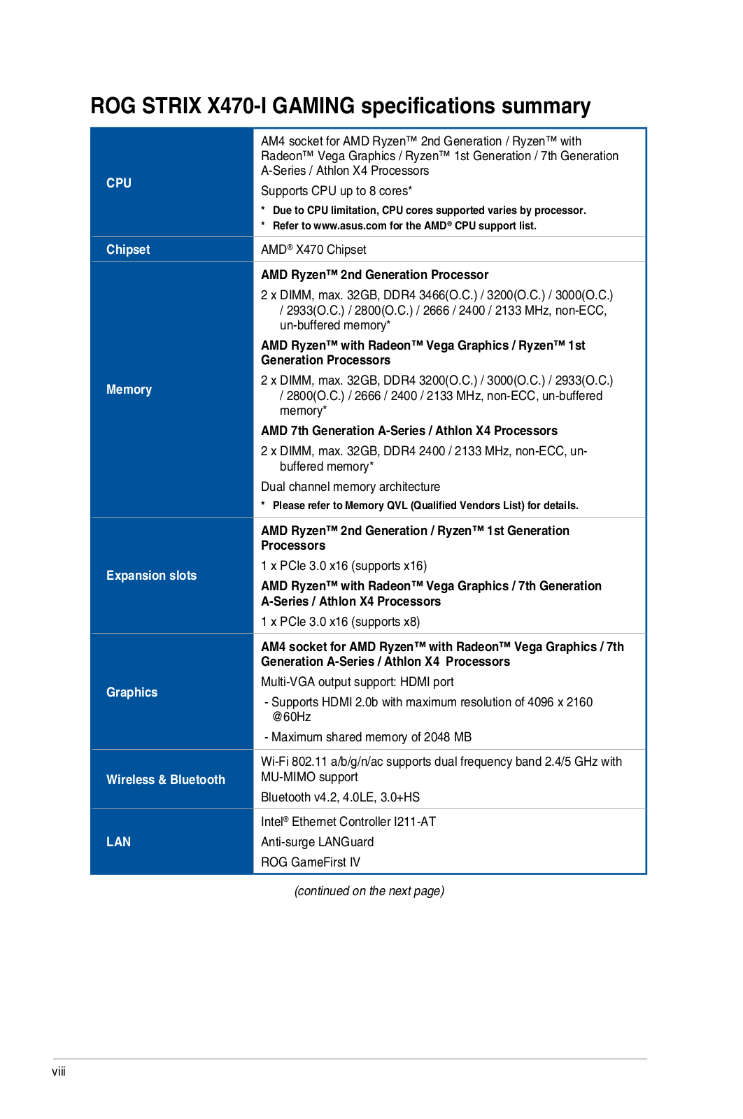
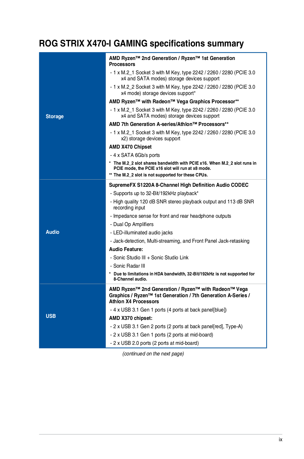
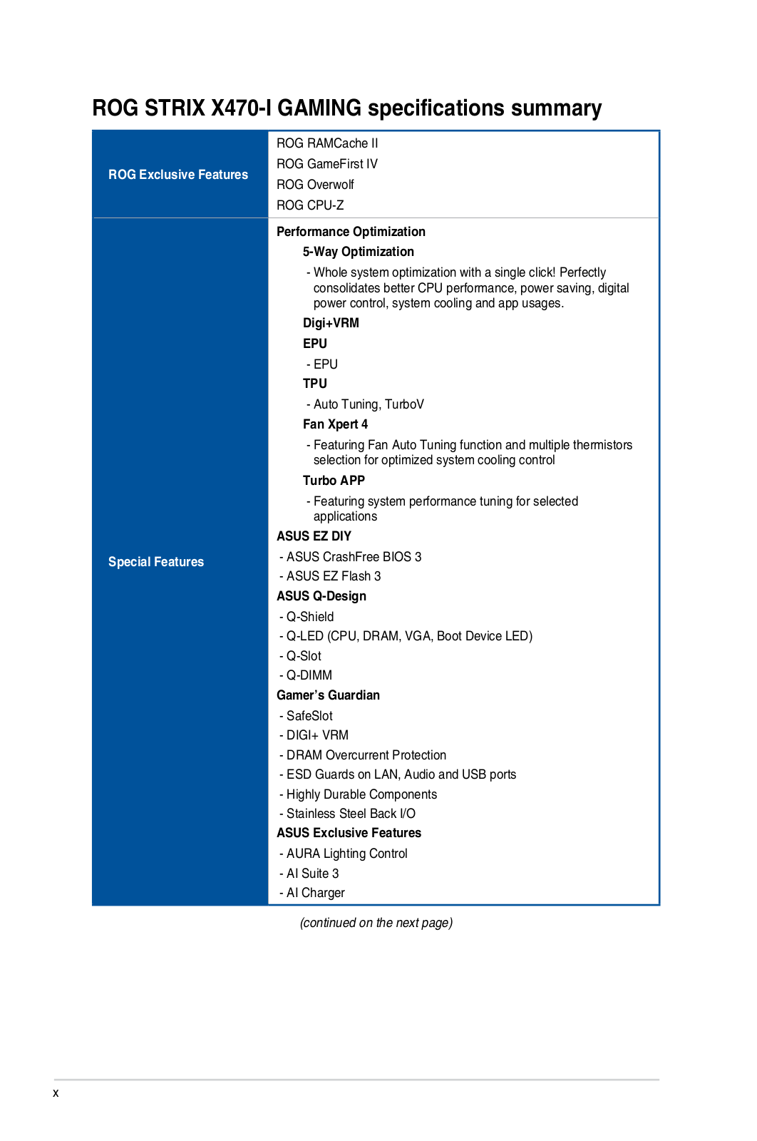
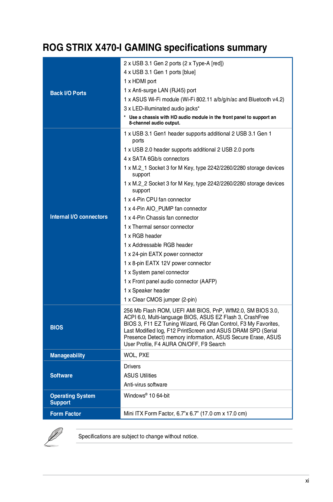
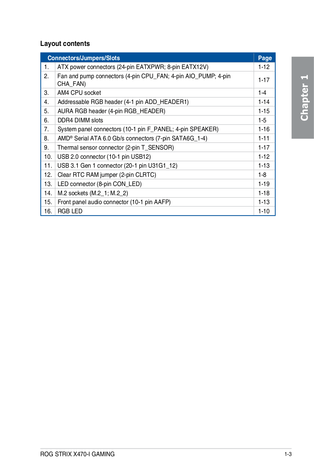
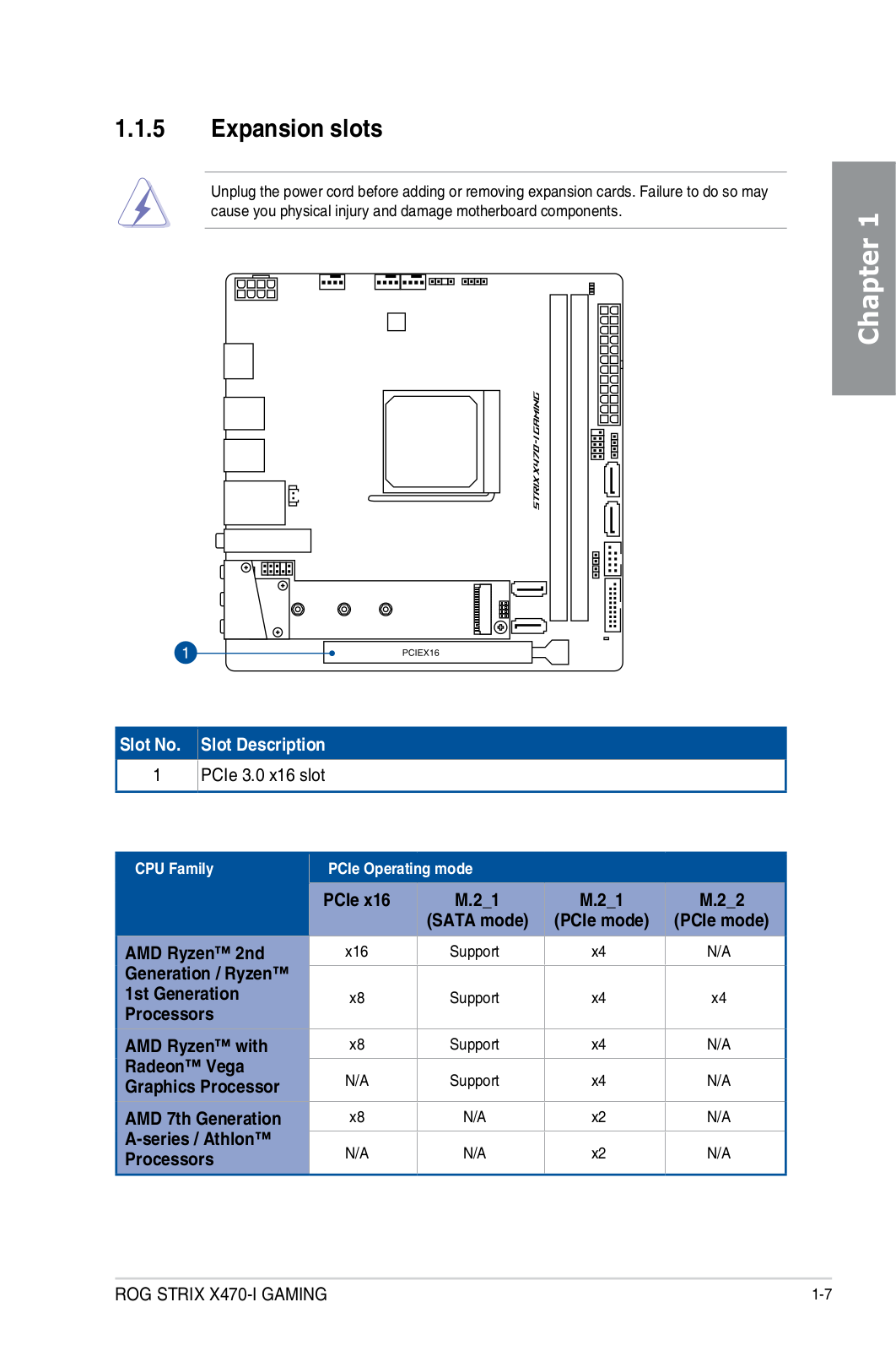
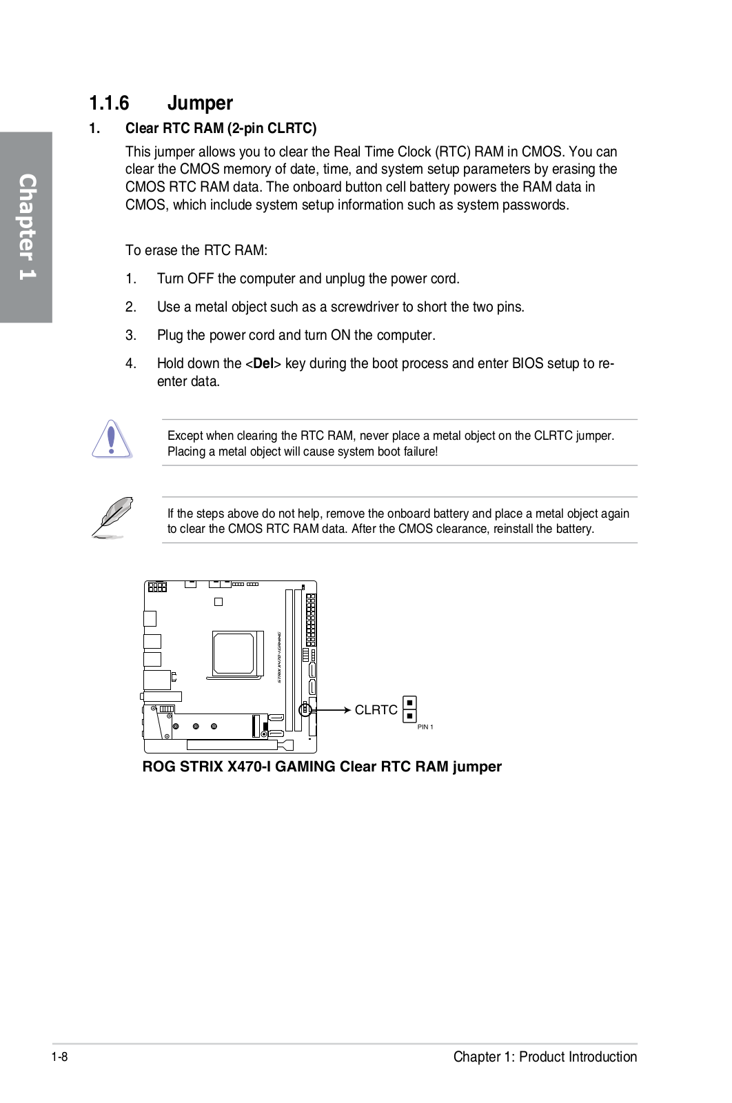
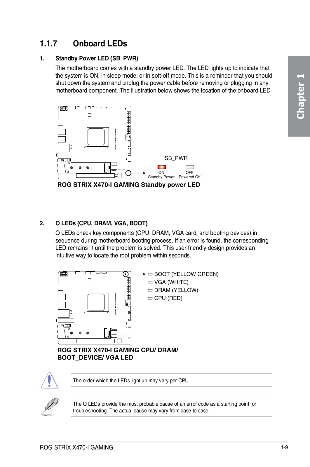
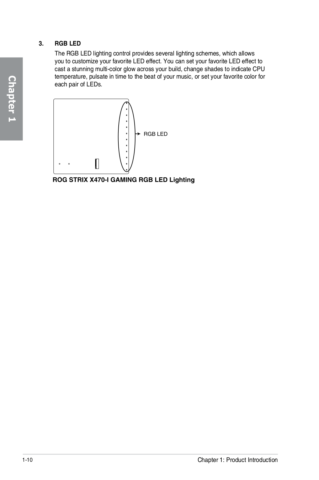
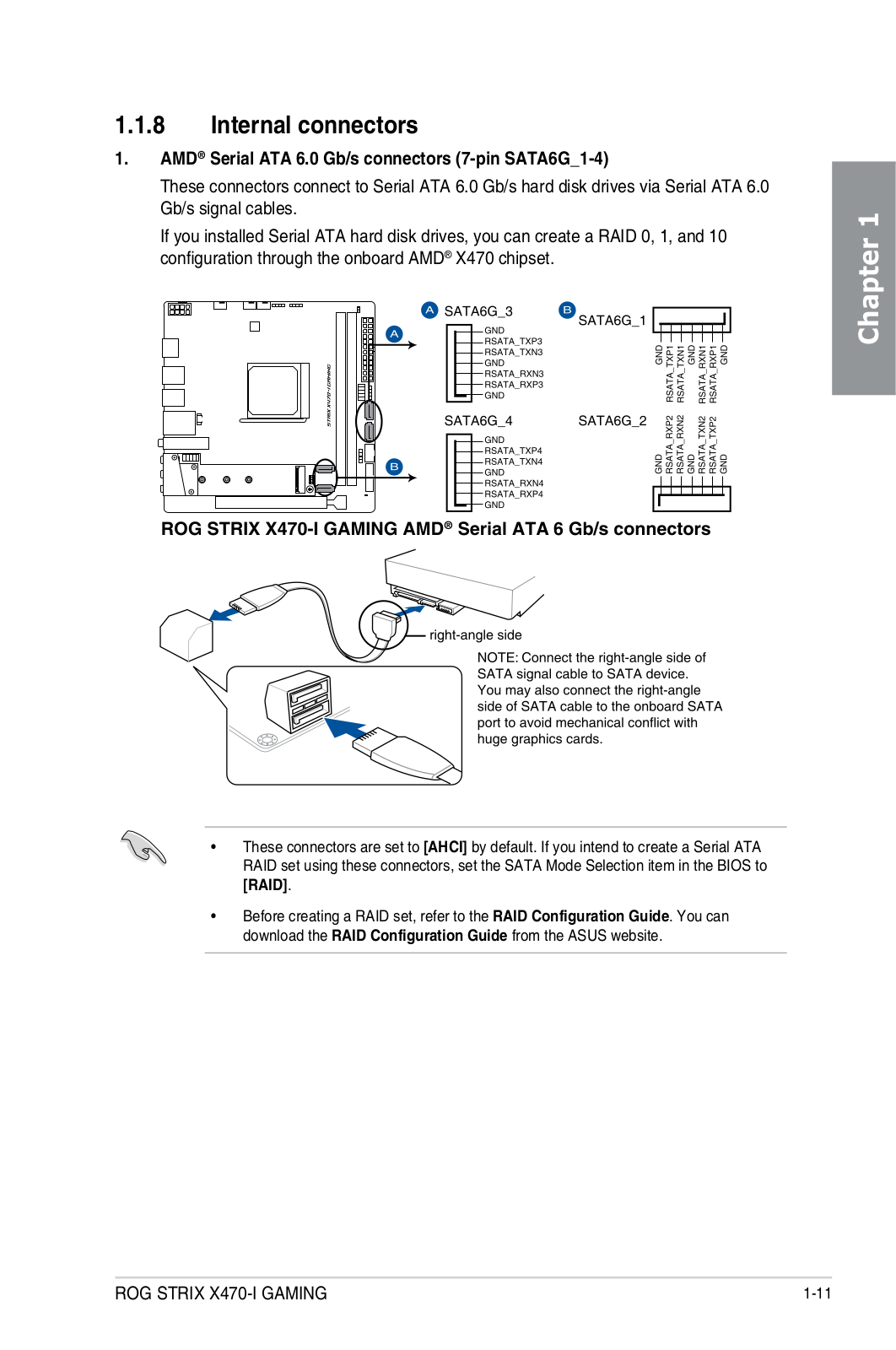
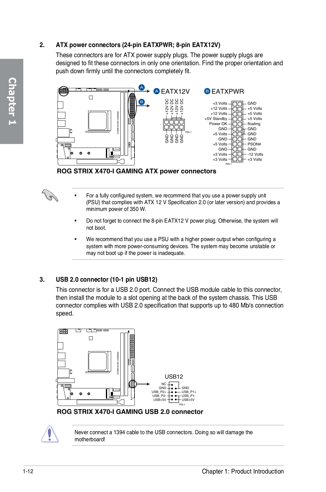
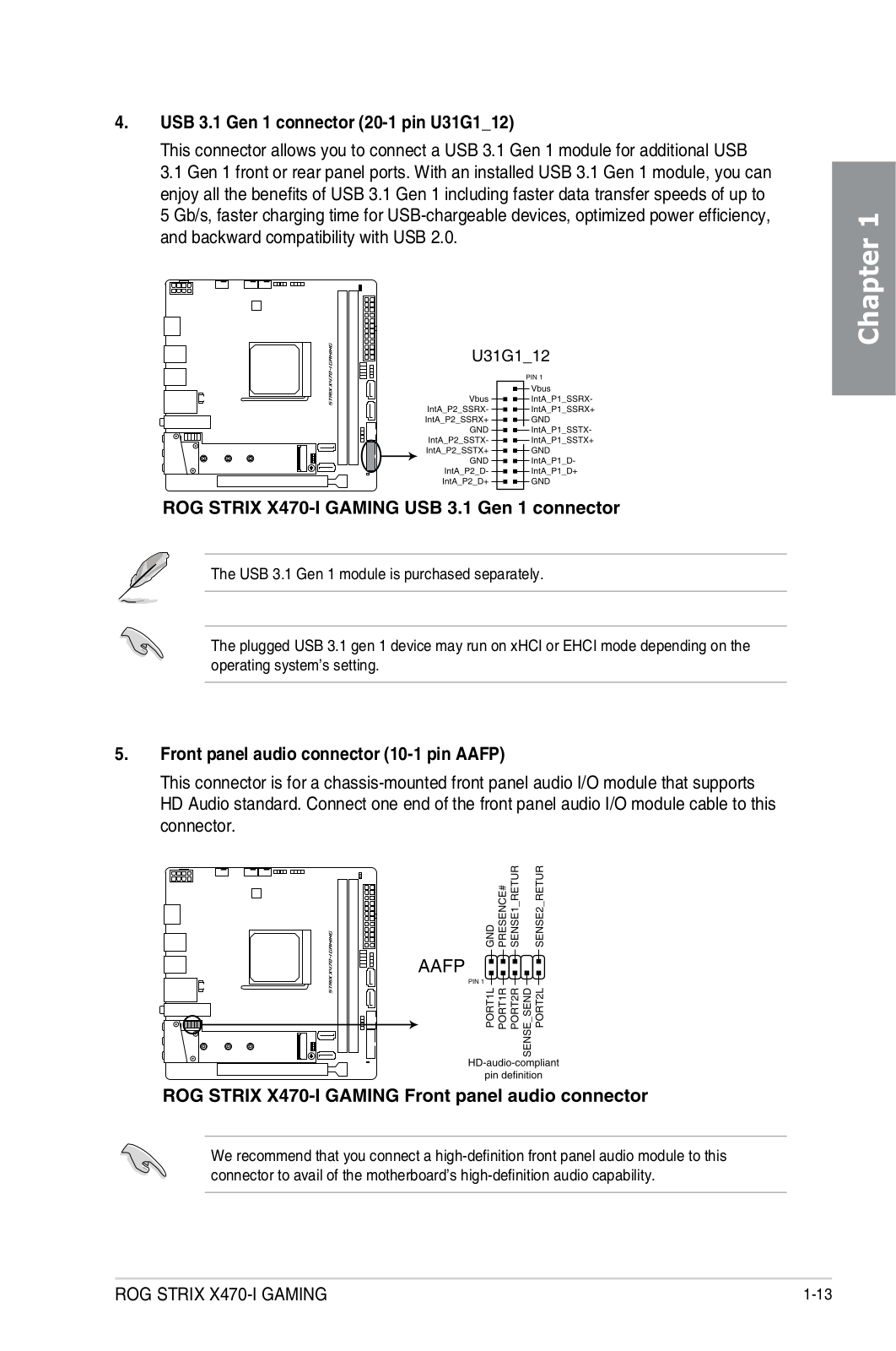
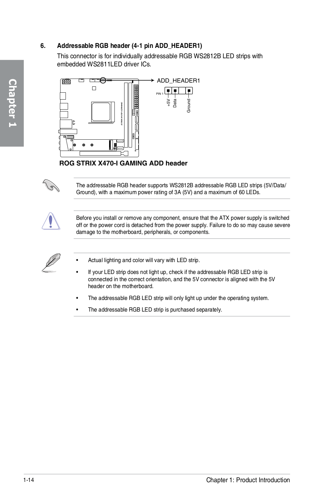
ROG Strix X470-I Gaming
Service Manual
92 pgs
7.51 Mb
0
Table of contents
Loading...
ASUS ROG Strix X470-I Gaming Service Manual
...
ASUS Service Manual
Download
Specifications and Main Features
Frequently Asked Questions
User Manual
Download
Loading...
+
64
hidden pages
Unhide
You need points to download manuals.
1 point = 1 manual.
You can buy points or you can get point for every manual you upload.
Buy points
Upload your manuals
 Loading...