

Page 1
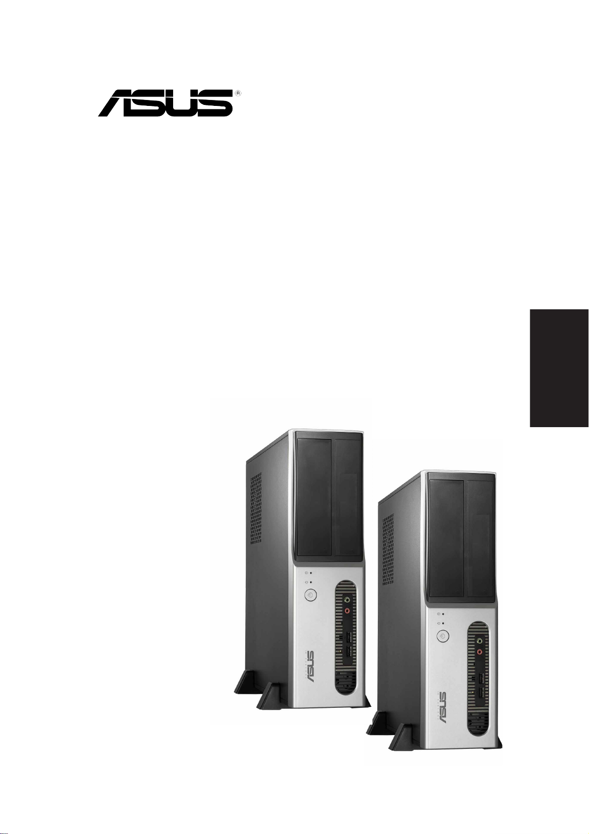
Pundit-PH3
Pundit-PE3
Barebone Systems
Quick Start Guide
English
Page 2
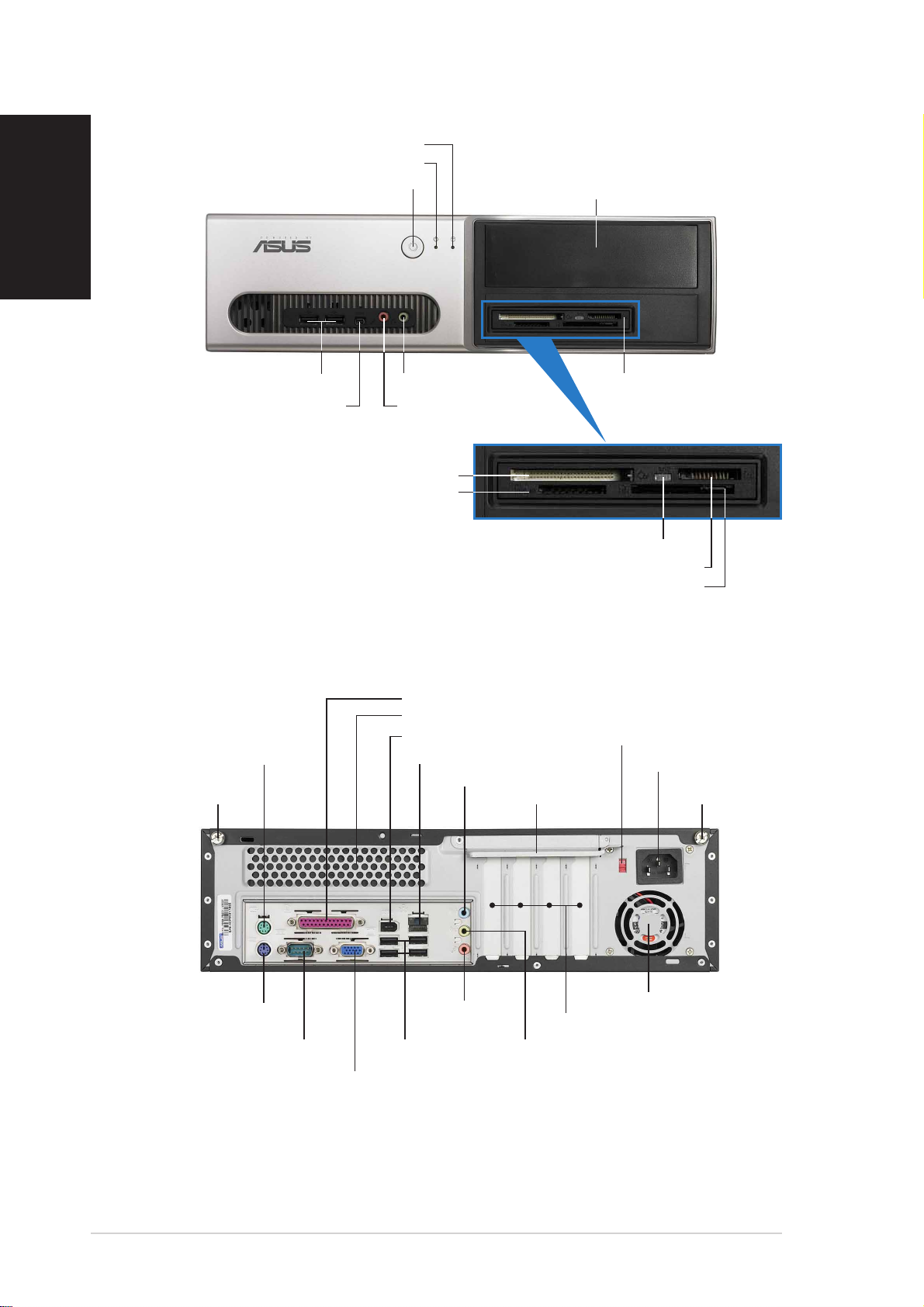
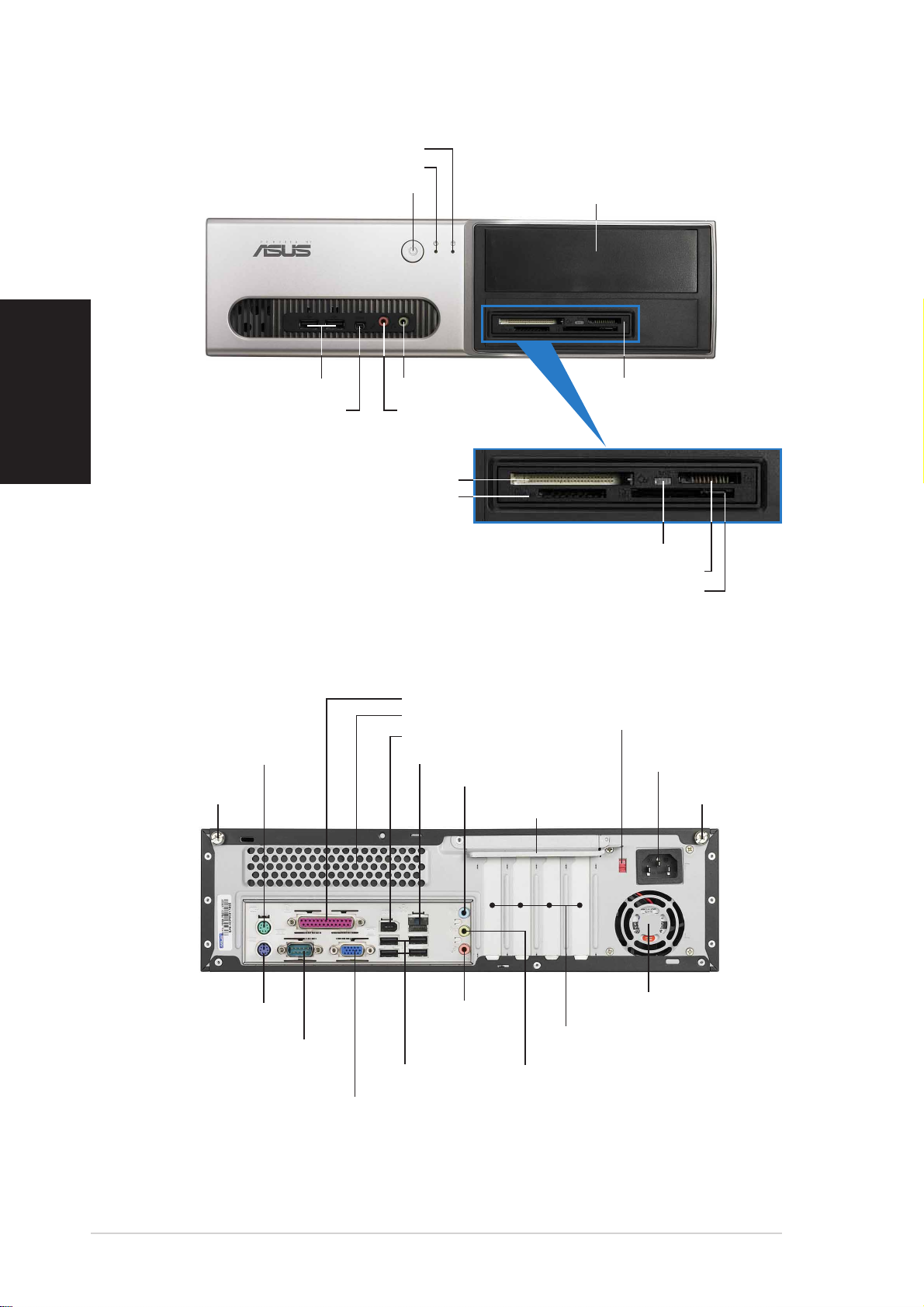
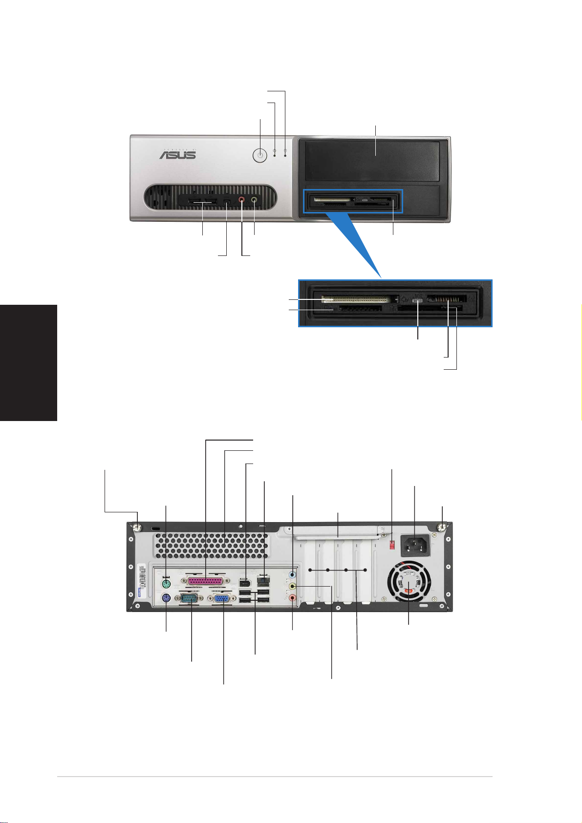
Front panel features
English
HDD LEDHDD LED
HDD LED
HDD LEDHDD LED
Power LEDPower LED
Power LED
Power LEDPower LED
Power buttonPower button
Power button
Power buttonPower button
5.25-inch drive bay cover5.25-inch drive bay cover
5.25-inch drive bay cover
5.25-inch drive bay cover5.25-inch drive bay cover
USB 2.0 portsUSB 2.0 ports
USB 2.0 ports
USB 2.0 portsUSB 2.0 ports
4-pin IEEE 1394a port4-pin IEEE 1394a port
4-pin IEEE 1394a port
4-pin IEEE 1394a port4-pin IEEE 1394a port
®®
®
CompactFlashCompactFlash
CompactFlash
CompactFlashCompactFlash
Secure Digital™/MultimediaCard slotSecure Digital™/MultimediaCard slot
Secure Digital™/MultimediaCard slot
Secure Digital™/MultimediaCard slotSecure Digital™/MultimediaCard slot
®®
Microphone portMicrophone port
Microphone port
Microphone portMicrophone port
Headphone portHeadphone port
Headphone port
Headphone portHeadphone port
card slot card slot
card slot
card slot card slot
*Pundit-PH3 model only
Memory StickMemory Stick
Memory Stick
Memory StickMemory Stick
Rear panel features
Parallel portParallel port
Parallel port
Parallel portParallel port
Air ventsAir vents
Air vents
Air ventsAir vents
IEEE 1394a portIEEE 1394a port
IEEE 1394a port
IEEE 1394a portIEEE 1394a port
LAN (RJ-45) portLAN (RJ-45) port
PS/2 mouse portPS/2 mouse port
PS/2 mouse port
PS/2 mouse portPS/2 mouse port
Cover screwCover screw
Cover screw
Cover screwCover screw
LAN (RJ-45) port
LAN (RJ-45) portLAN (RJ-45) port
Line In portLine In port
Line In port
Line In portLine In port
6-in-1 card reader*6-in-1 card reader*
6-in-1 card reader*
6-in-1 card reader*6-in-1 card reader*
Card reader LEDCard reader LED
Card reader LED
Card reader LEDCard reader LED
®®
®
®®
/Pro™ card slot/Pro™ card slot
/Pro™ card slot
/Pro™ card slot/Pro™ card slot
®®
®
SmartMediaSmartMedia
SmartMedia
SmartMediaSmartMedia
Metal bracket lockMetal bracket lock
Metal bracket lock
Metal bracket lockMetal bracket lock
®®
card slot card slot
card slot
card slot card slot
Voltage selectorVoltage selector
Voltage selector
Voltage selectorVoltage selector
Power connectorPower connector
Power connector
Power connectorPower connector
Cover screwCover screw
Cover screw
Cover screwCover screw
PS/2 keyboard portPS/2 keyboard port
PS/2 keyboard port
PS/2 keyboard portPS/2 keyboard port
22
2
22
Serial portSerial port
Serial port
Serial portSerial port
VGA portVGA port
VGA port
VGA portVGA port
Quick Installation GuideQuick Installation Guide
Quick Installation Guide
Quick Installation GuideQuick Installation Guide
Line OutLine Out
Line Out
Line OutLine Out
portport
port
portport
USB 2.0 portsUSB 2.0 ports
USB 2.0 ports
USB 2.0 portsUSB 2.0 ports
Power fan ventsPower fan vents
Power fan vents
Power fan ventsPower fan vents
PCI slot metal bracketsPCI slot metal brackets
PCI slot metal brackets
PCI slot metal bracketsPCI slot metal brackets
Microphone portMicrophone port
Microphone port
Microphone portMicrophone port
Page 3
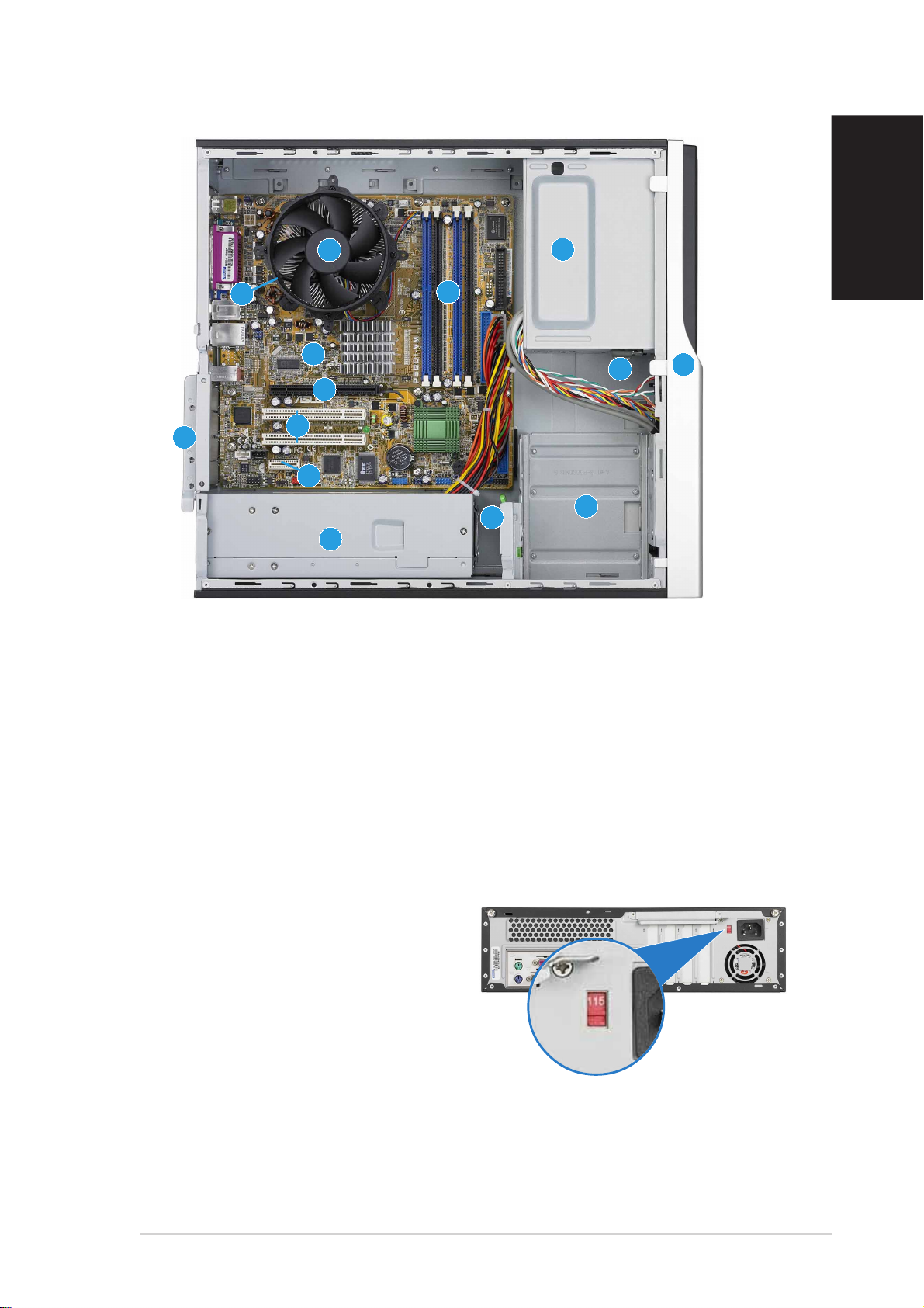
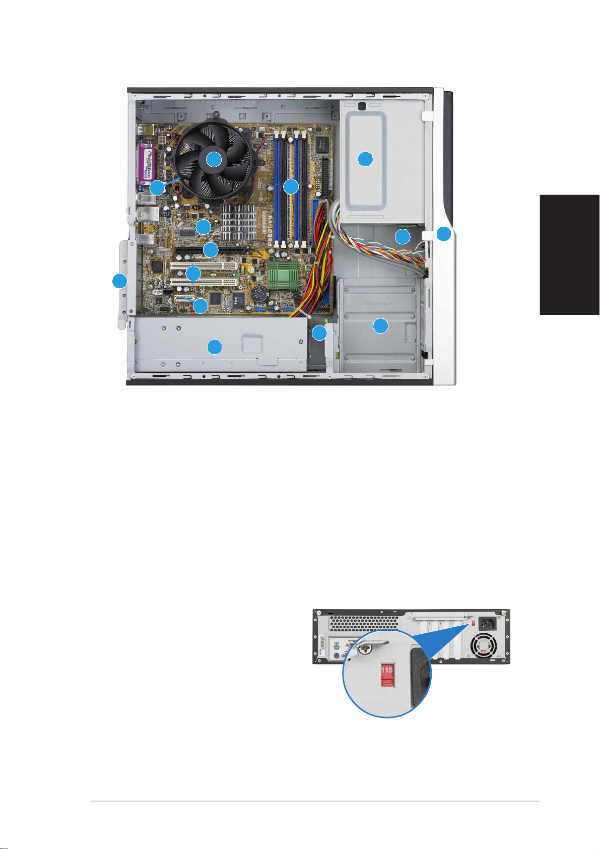
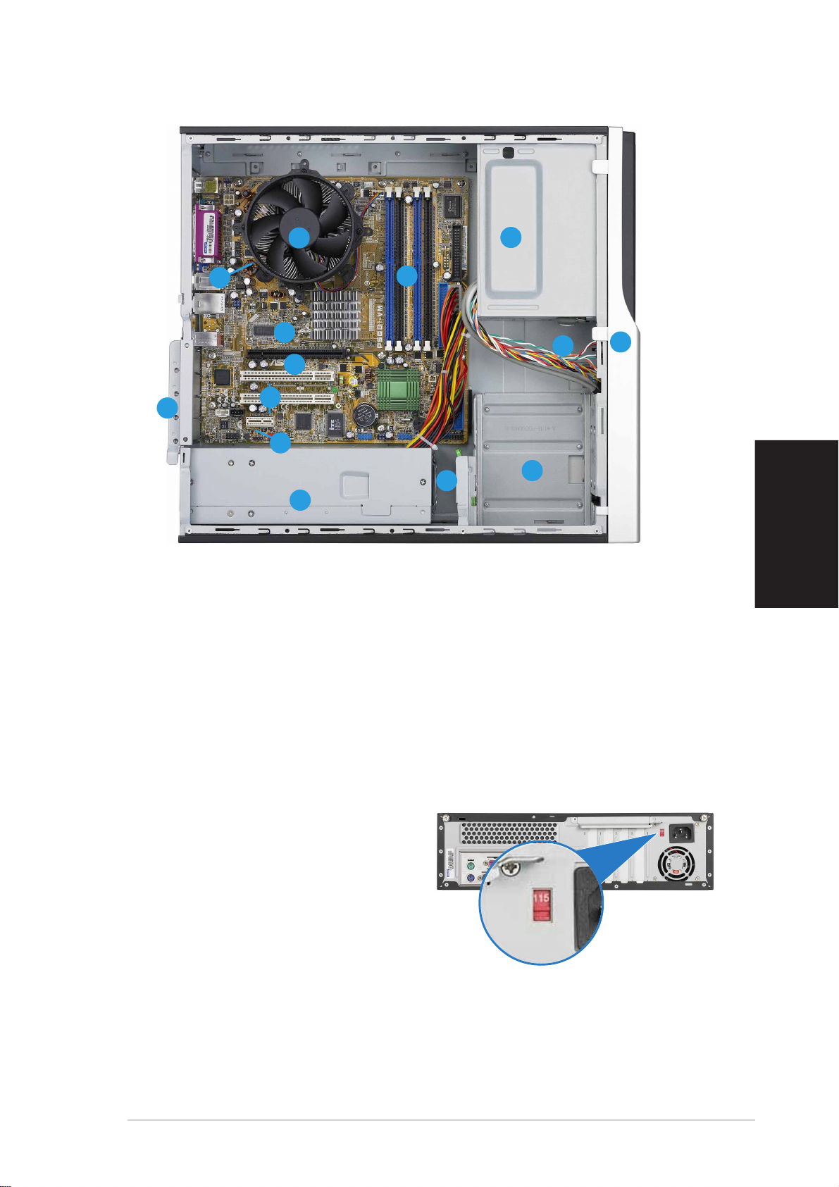
Internal components
11
33
1
3
11
33
1414
14
11
22
1
2
11
22
1010
10
1010
99
9
99
88
8
11
11
1
1
11
11
88
77
7
77
66
6
66
1414
1. 5.25-inch empty optical drive bay
2. Front panel cover
3. Optical drive lock
4. Hard disk drive bays
5. Hard disk drive lock
6. Power supply unit
7. PCI Express x1 slot
8. PCI slots
11
1
11
22
2
33
3
33
44
4
55
5
55
44
22
9. PCI Express x16 slot
(on Pundit-PH3 model only)
10. ASUS motherboard
11. Metal bracket lock
12. LGA775 socket
(under the CPU
fan and heatsink assembly)
13. CPU fan and heatsink assembly
14. DIMM sockets
English
Selecting the voltage
The system’s power supply unit has
a 115 V/230 V voltage selector
switch located beside the power
connector. Use this switch to select
the appropriate system input voltage
according to the voltage supply in
your area.
If the voltage supply in your area is
100-127 V, set the switch to 115 V.
If the voltage supply in your area is
200-240 V, set the switch to 230 V.
Quick Installation GuideQuick Installation Guide
Quick Installation Guide
Quick Installation GuideQuick Installation Guide
33
3
33
Page 4
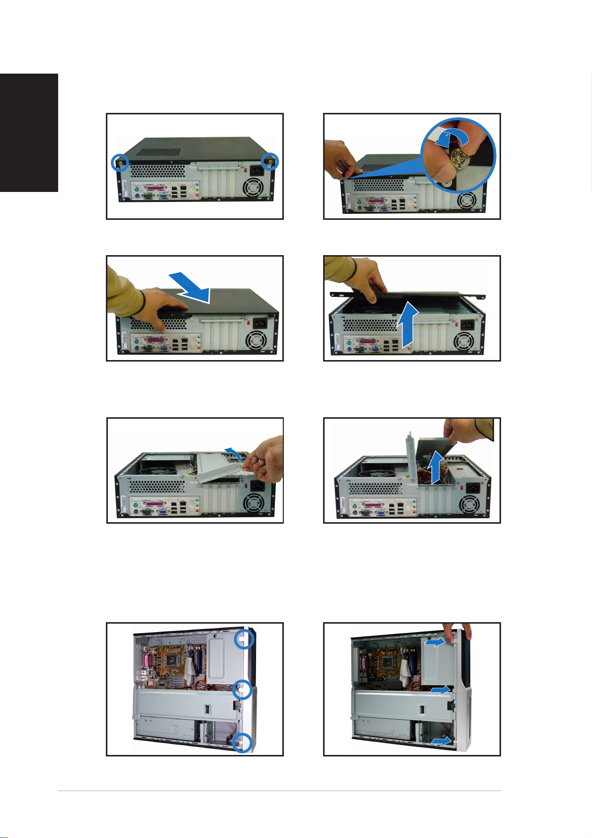
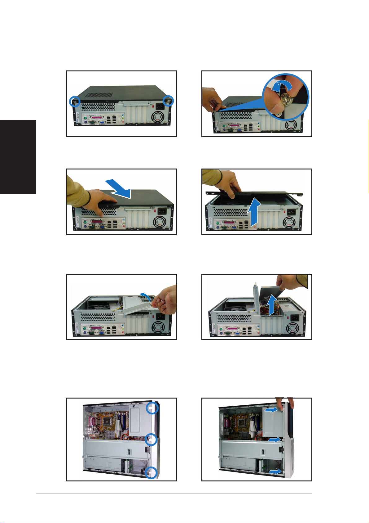
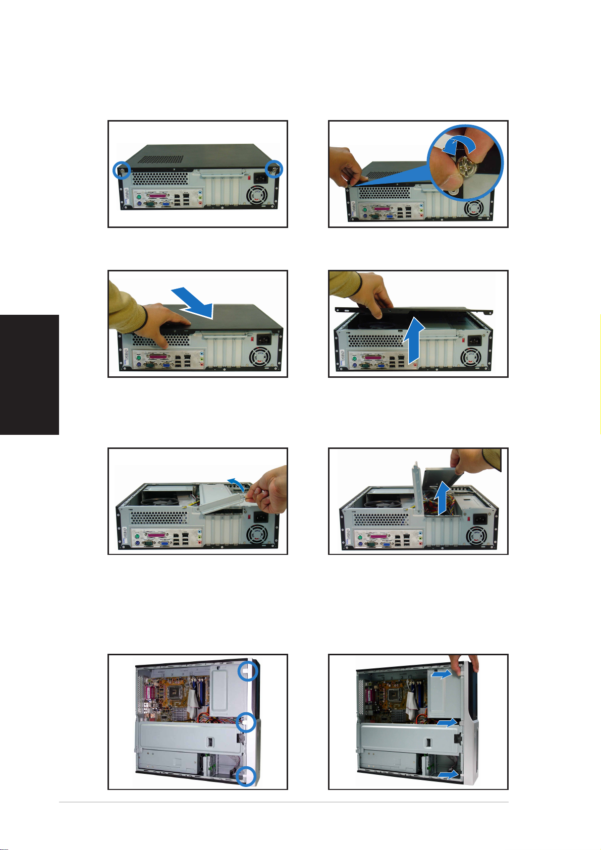
Removing the cover
English
1. Locate two cover screws.
3. Pull the cover.
2. Remove the cover screws.
4. Lift the cover, then set aside.
5. Lift the expansion card lock to
a 90º-100º angle.
6. Lift the chassis support
bracket, then remove.
Removing the front panel assembly
1. Locate the front panel
assembly hooks.
2. Pull the hooks outward to
remove.
44
4
44
Quick Installation GuideQuick Installation Guide
Quick Installation Guide
Quick Installation GuideQuick Installation Guide
Page 5
Installing a CPU
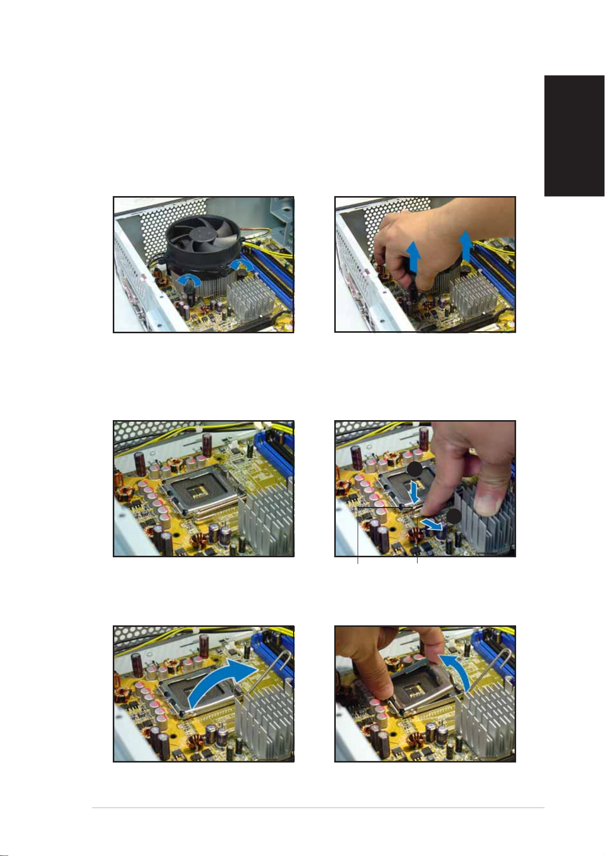
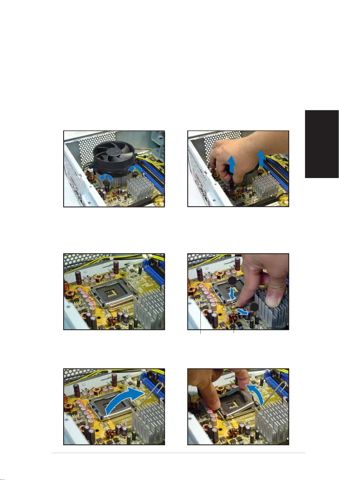
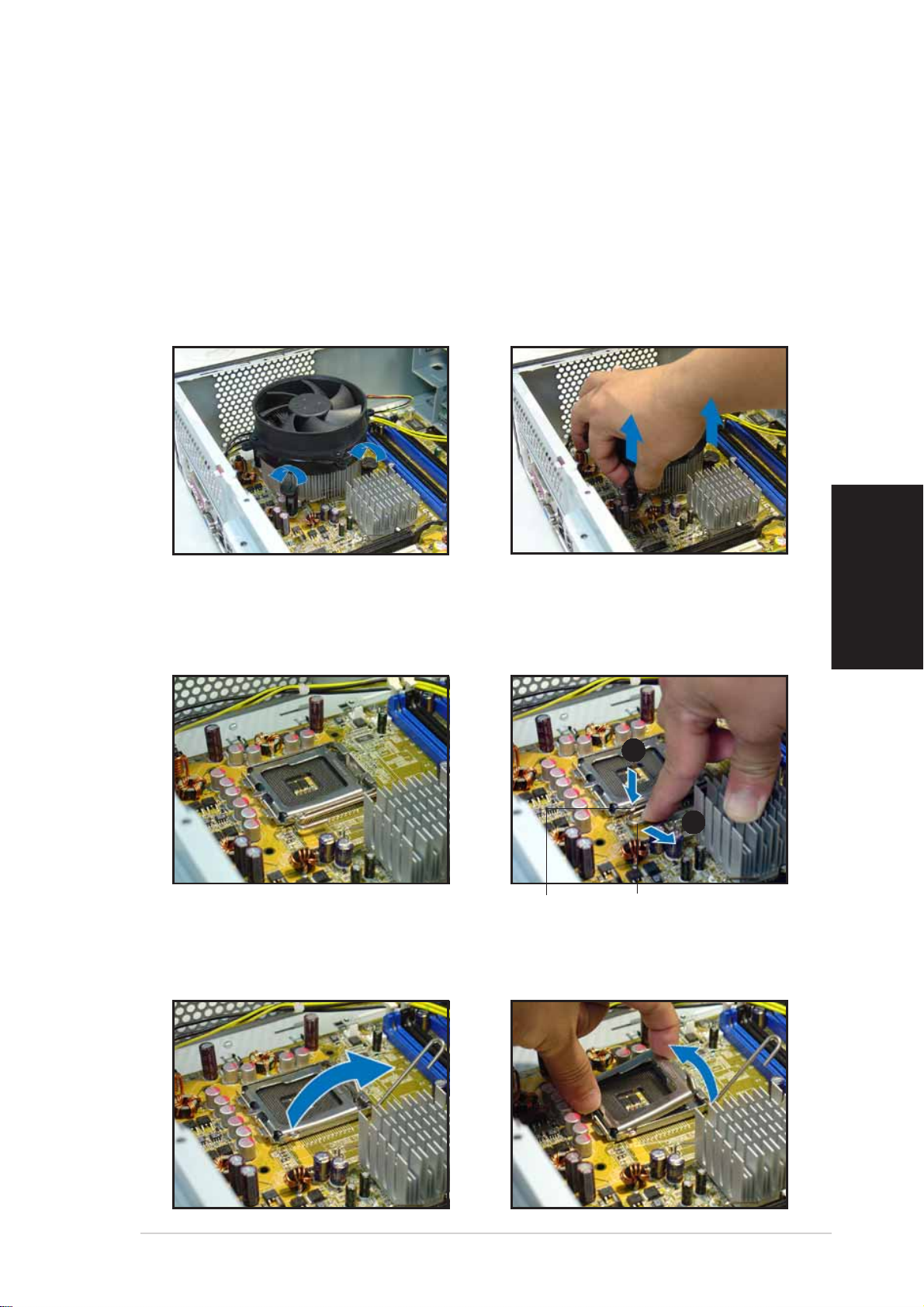
Removing the CPU fan and heatsink assemblyRemoving the CPU fan and heatsink assembly
Removing the CPU fan and heatsink assembly
Removing the CPU fan and heatsink assemblyRemoving the CPU fan and heatsink assembly
1. Disconnect the CPU fan cable.
2. Rotate the fasteners
counterclockwise.
Installing the CPUInstalling the CPU
Installing the CPU
Installing the CPUInstalling the CPU
1. Locate the CPU socket.
3. Pull two fasteners at a time to
remove the fan and heatsink.
4. After removing the fan, rotate
each fastener clockwise.
2. Unlock the load lever.
English
AA
A
AA
Retention tabRetention tab
Retention tab
Retention tabRetention tab
Load leverLoad lever
Load lever
Load leverLoad lever
3. Lift the load lever. 4. Lift the load plate.
BB
B
BB
Quick Installation GuideQuick Installation Guide
Quick Installation Guide
Quick Installation GuideQuick Installation Guide
55
5
55
Page 6
English
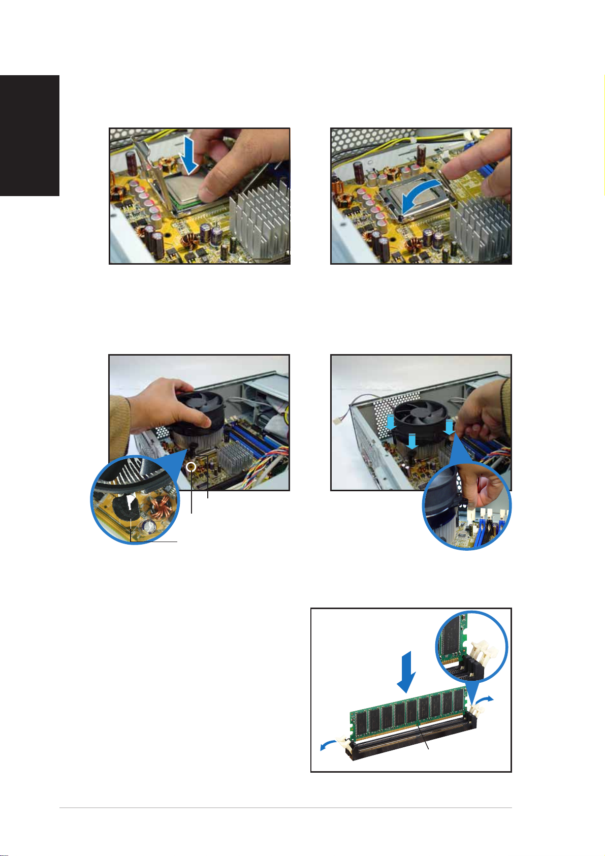
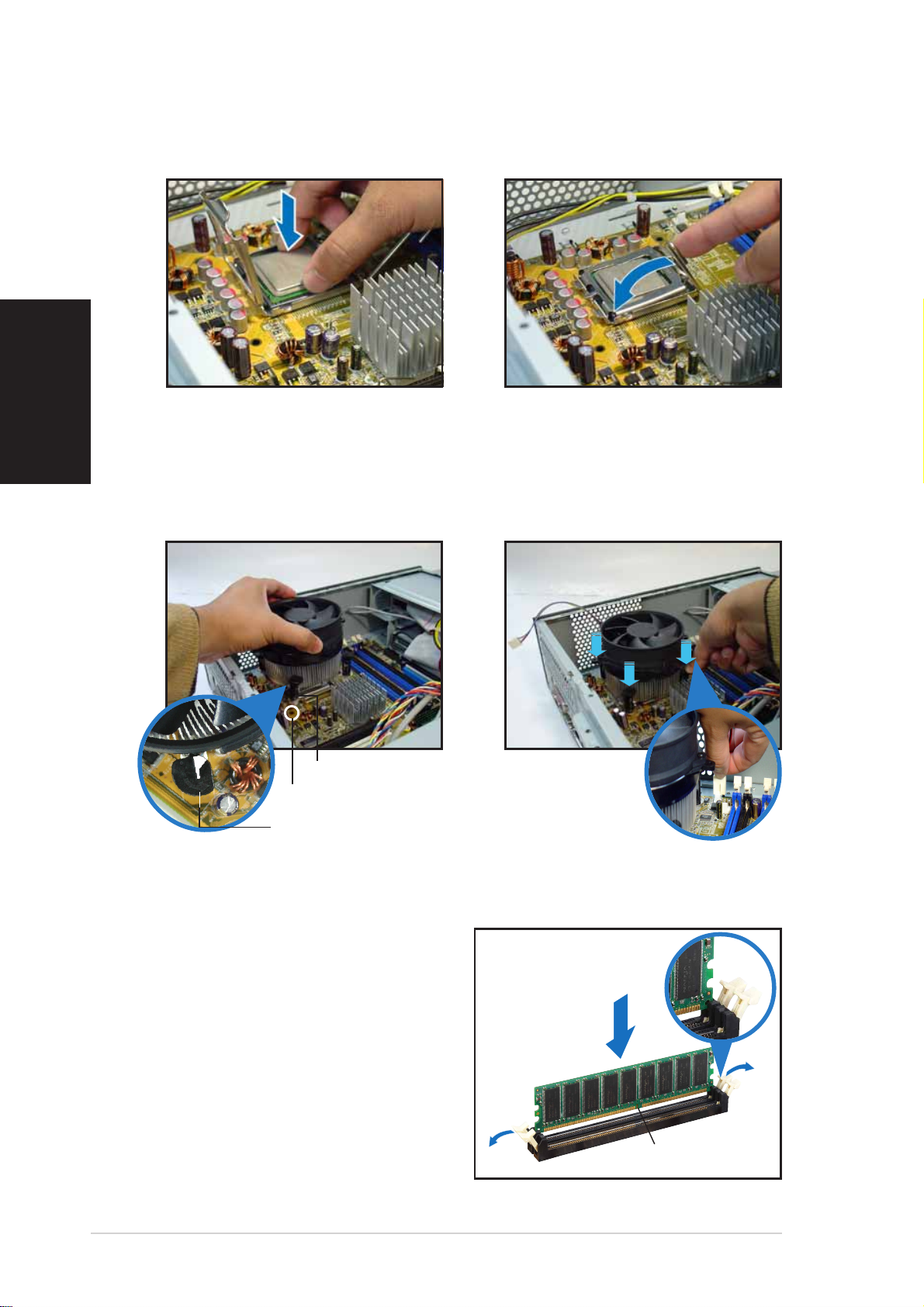
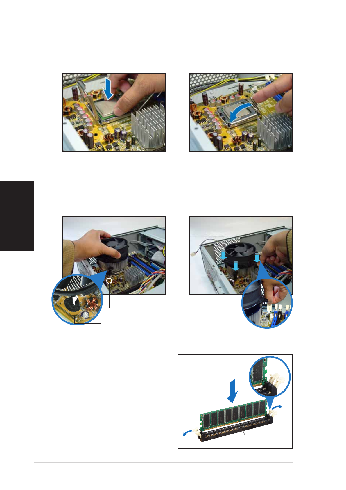
5. Install the CPU.
Reinstalling the CPU fan and heatsink assemblyReinstalling the CPU fan and heatsink assembly
Reinstalling the CPU fan and heatsink assembly
Reinstalling the CPU fan and heatsink assemblyReinstalling the CPU fan and heatsink assembly
6. Close the load plate, then lock
the load lever.
1. Place the heatsink on top of
the installed CPU.
FastenerFastener
Fastener
FastenerFastener
Motherboard holeMotherboard hole
Motherboard hole
Motherboard holeMotherboard hole
Narrow end of the grooveNarrow end of the groove
Narrow end of the groove
Narrow end of the grooveNarrow end of the groove
Installing a DIMM
1. Locate the DIMM sockets in the
motherboard.
2. Unlock a DIMM socket by
pressing the retaining clips
outward.
2. Push down the fasteners.
3. Connect the CPU fan cable.
UnlockedUnlocked
Unlocked
UnlockedUnlocked
retaining clipretaining clip
retaining clip
retaining clipretaining clip
3. Align a DIMM on the socket such
that the notch on the DIMM
matches the break on the
socket.
66
6
66
Quick Installation GuideQuick Installation Guide
Quick Installation Guide
Quick Installation GuideQuick Installation Guide
DDR DIMM notchDDR DIMM notch
DDR DIMM notch
DDR DIMM notchDDR DIMM notch
Page 7
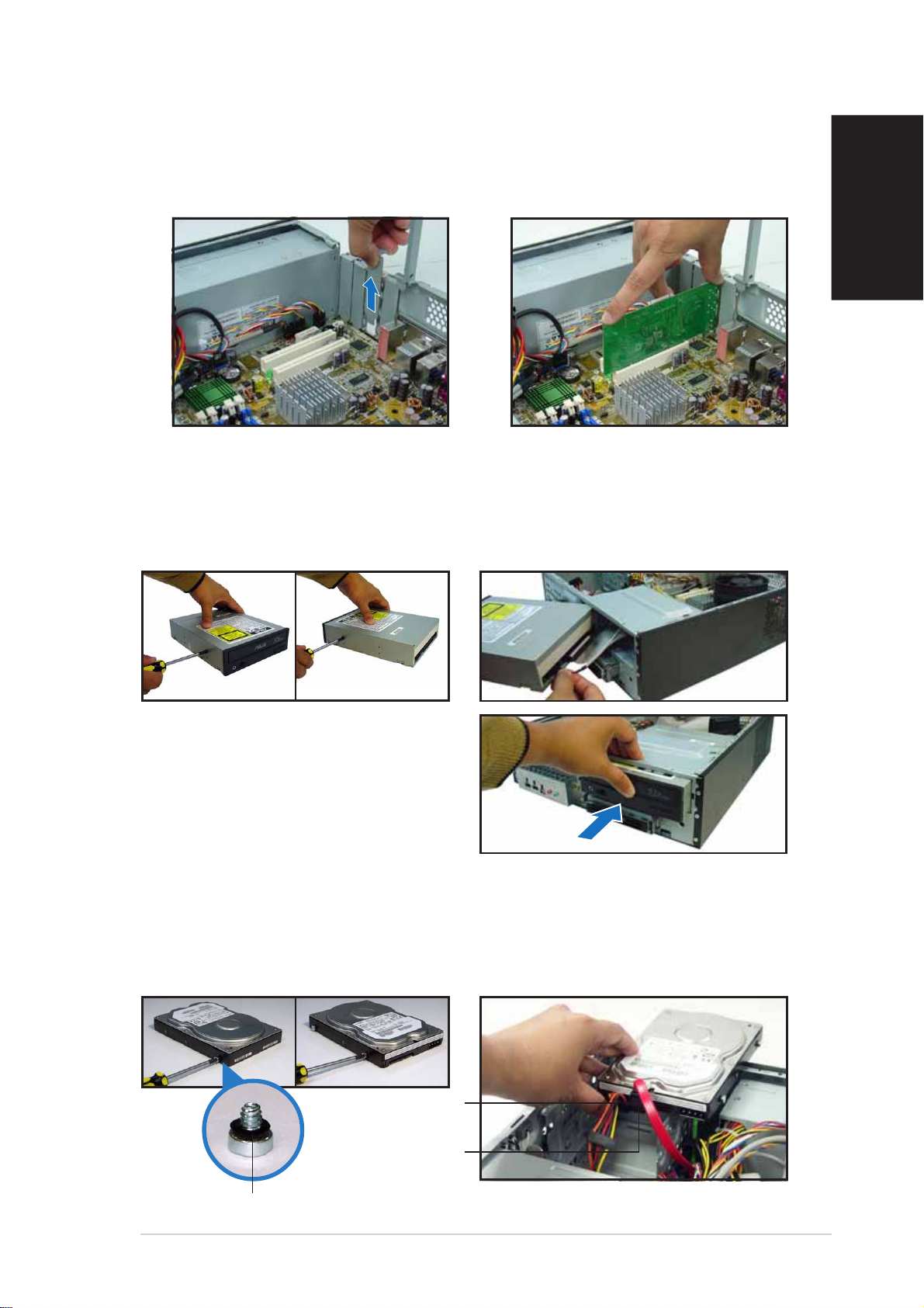
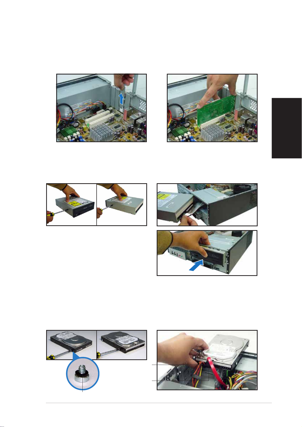
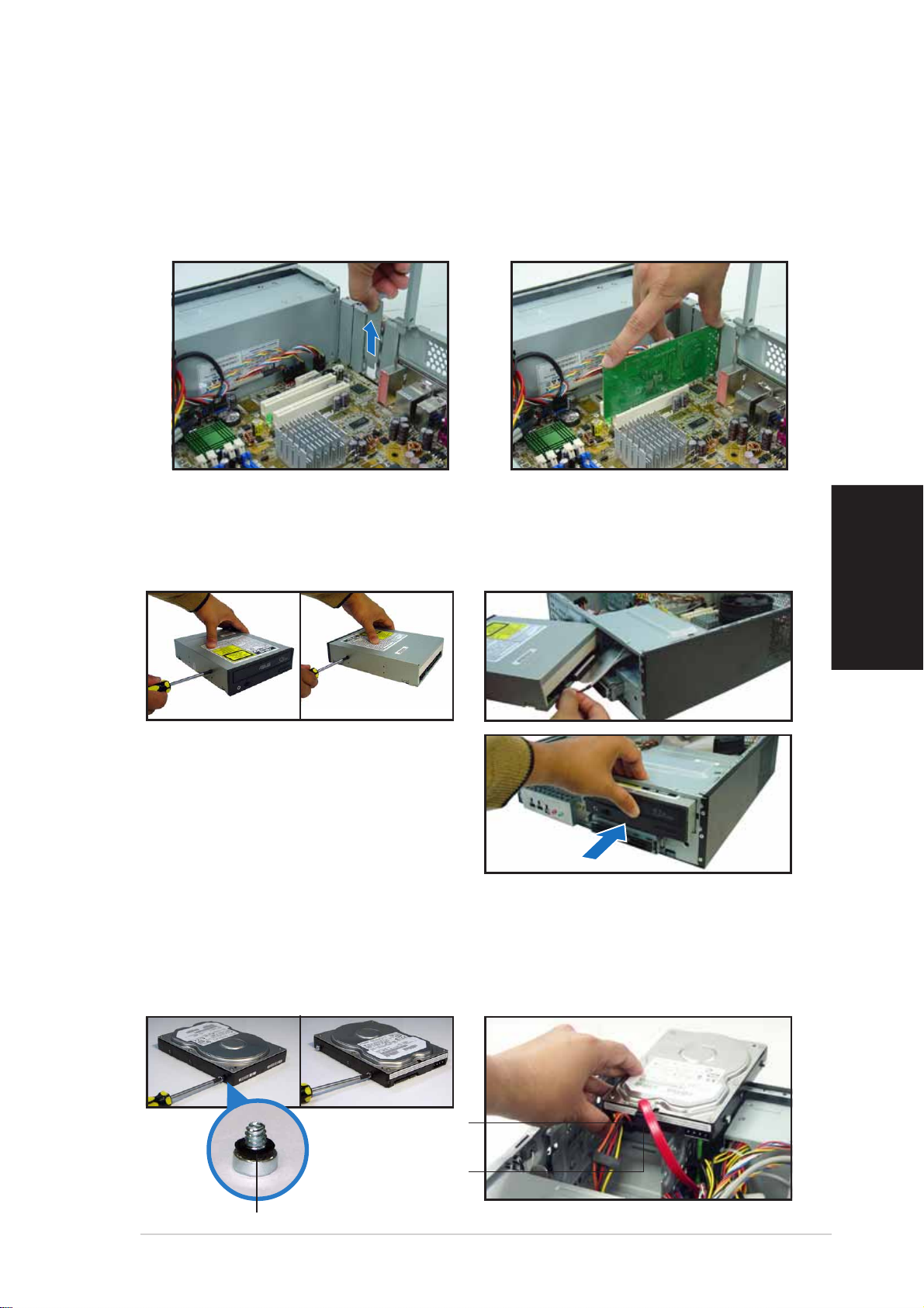
Installing an expansion card
1. Remove the metal cover
opposite the slot that you
intend to use.
2. Insert the card connector to
the slot, then press the card
firmly until it fits in place.
Installing an optical drive
1. Drive a screw on the top right
screw hole on both sides of
the drive.
2. Connect the IDE and audio
cable at the back of the drive.
English
3. Push the drive all the way into
the bay until the drive lock clicks.
4. Connect a 4-pin power plug
from the power supply unit to
the power connector at the
back of the drive.
Installing a SATA hard disk drive
1. Drive two screws with rubber
washers on both sides of the
drive.
Power cablePower cable
Power cable
Power cablePower cable
and plugand plug
and plug
and plugand plug
Signal cableSignal cable
Signal cable
Signal cableSignal cable
and plugand plug
and plug
and plugand plug
2. Connect the SATA signal and
power plug at the back of the
drive.
Rubber washerRubber washer
Rubber washer
Rubber washerRubber washer
Quick Installation GuideQuick Installation Guide
Quick Installation Guide
Quick Installation GuideQuick Installation Guide
77
7
77
Page 8
English
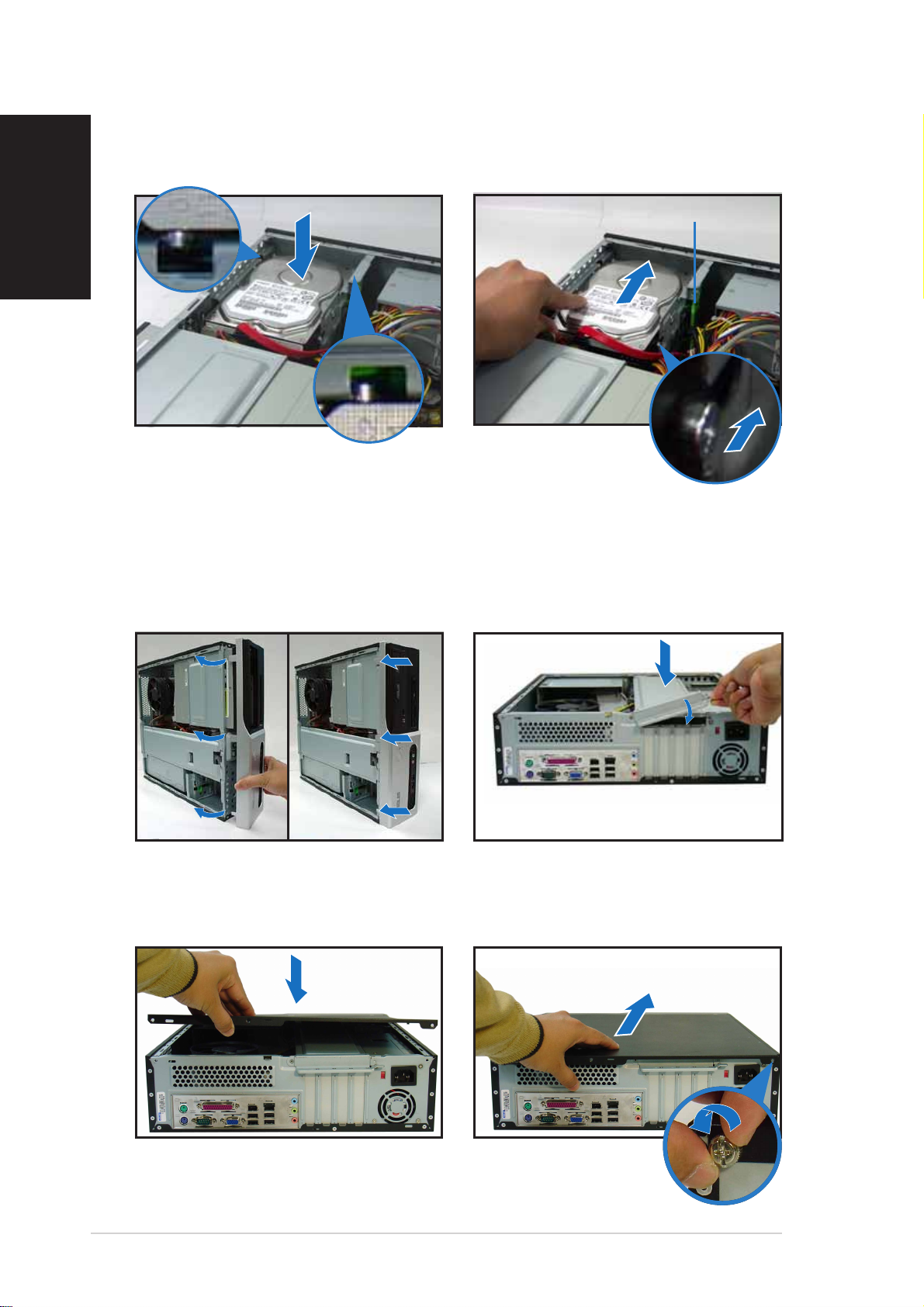
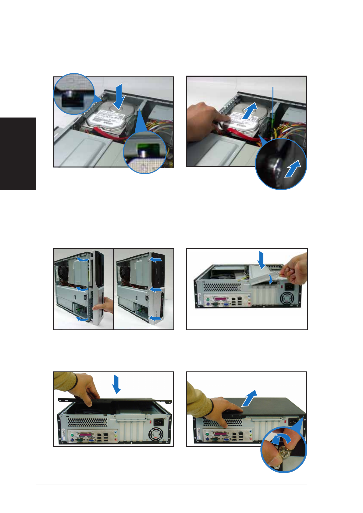
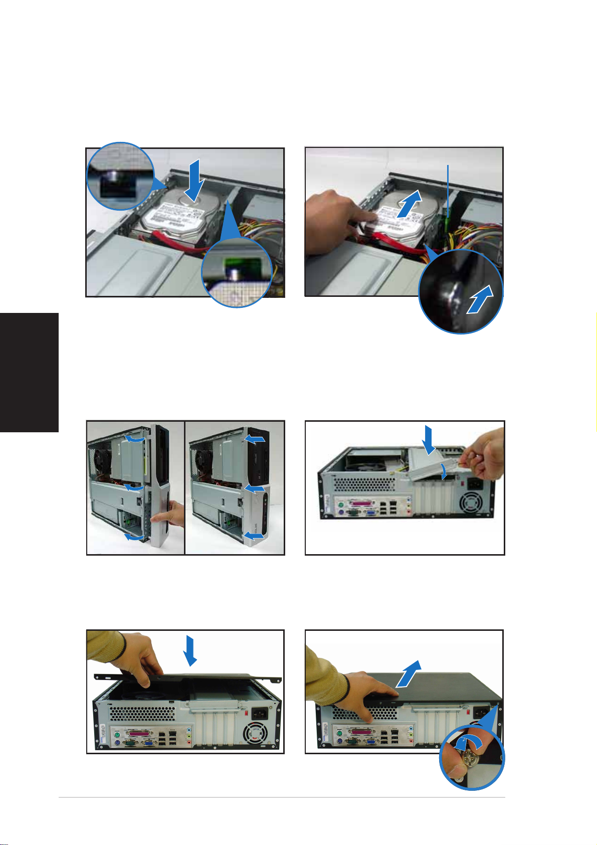
3. Place the HDD on the tray. 4. When the HDD screws align,
Replacing the covers
push the drive on the bay.
HDD screw lockHDD screw lock
HDD screw lock
HDD screw lockHDD screw lock
1. Replace the front panel
assembly. Remove the 5.25”
drive bay cover when you
installed an optical drive.
3. Insert the cover hooks to the
holes on the chassis side.
2. Reinstall the metal chassis
support and the expansion
card lock.
4. Push the cover to the direction
of the front panel, then
replace the cover screws.
88
8
88
Quick Installation GuideQuick Installation Guide
Quick Installation Guide
Quick Installation GuideQuick Installation Guide
Page 9
Pundit-PH3
Pundit-PE3
Système barebone
Guide de démarrage rapide
Français
Page 10
Caractéristiques de la façade
Français
LED HDDLED HDD
LED HDD
LED HDDLED HDD
LED d’alimentationLED d’alimentation
LED d’alimentation
LED d’alimentationLED d’alimentation
Bouton d’alimentationBouton d’alimentation
Bouton d’alimentation
Bouton d’alimentationBouton d’alimentation
Cache de baie 5.25 poucesCache de baie 5.25 pouces
Cache de baie 5.25 pouces
Cache de baie 5.25 poucesCache de baie 5.25 pouces
Ports USB 2.0Ports USB 2.0
Ports USB 2.0
Ports USB 2.0Ports USB 2.0
Port IEEE 1394a 4Port IEEE 1394a 4
Port IEEE 1394a 4
Port IEEE 1394a 4Port IEEE 1394a 4
brochesbroches
broches
brochesbroches
Slot pour cartes CompactFlashSlot pour cartes CompactFlash
Slot pour cartes CompactFlash
Slot pour cartes CompactFlashSlot pour cartes CompactFlash
Slot Secure Digital™/MultimediaCardSlot Secure Digital™/MultimediaCard
Slot Secure Digital™/MultimediaCard
Slot Secure Digital™/MultimediaCardSlot Secure Digital™/MultimediaCard
*Modèle Pundit-PH3 uniquement
Port MicrophonePort Microphone
Port Microphone
Port MicrophonePort Microphone
Port CasquePort Casque
Port Casque
Port CasquePort Casque
®®
®
®®
LED lecteur de cartesLED lecteur de cartes
LED lecteur de cartes
LED lecteur de cartesLED lecteur de cartes
Slot pour cartes Memory StickSlot pour cartes Memory Stick
Slot pour cartes Memory Stick
Slot pour cartes Memory StickSlot pour cartes Memory Stick
Slot pour cartes SmartMediaSlot pour cartes SmartMedia
Slot pour cartes SmartMedia
Slot pour cartes SmartMediaSlot pour cartes SmartMedia
Caractéristiques de l’arrière
Port parallèlePort parallèle
Port parallèle
Port parallèlePort parallèle
AérationsAérations
Aérations
AérationsAérations
Port IEEE 1394aPort IEEE 1394a
Port IEEE 1394a
Port IEEE 1394aPort IEEE 1394a
Port LAN (RJ-45)Port LAN (RJ-45)
Port souris PS/2Port souris PS/2
Port souris PS/2
Port souris PS/2Port souris PS/2
Vis du capotVis du capot
Vis du capot
Vis du capotVis du capot
Port LAN (RJ-45)
Port LAN (RJ-45)Port LAN (RJ-45)
Port Line InPort Line In
Port Line In
Port Line InPort Line In
Verrouillage desVerrouillage des
Verrouillage des
Verrouillage desVerrouillage des
brackets métalliquesbrackets métalliques
brackets métalliques
brackets métalliquesbrackets métalliques
Lecteur de cartesLecteur de cartes
Lecteur de cartes
Lecteur de cartesLecteur de cartes
6-en-1*6-en-1*
6-en-1*
6-en-1*6-en-1*
®®
®
®®
/Pro™/Pro™
/Pro™
/Pro™/Pro™
®®
®
®®
Sélecteur de tensionSélecteur de tension
Sélecteur de tension
Sélecteur de tensionSélecteur de tension
ConnecteurConnecteur
Connecteur
ConnecteurConnecteur
d’alimentationd’alimentation
d’alimentation
d’alimentationd’alimentation
Vis du capotVis du capot
Vis du capot
Vis du capotVis du capot
Port clavier PS/2Port clavier PS/2
Port clavier PS/2
Port clavier PS/2Port clavier PS/2
22
2
22
Port SériePort Série
Port Série
Port SériePort Série
Port VGAPort VGA
Port VGA
Port VGAPort VGA
Guide de démarrage rapideGuide de démarrage rapide
Guide de démarrage rapide
Guide de démarrage rapideGuide de démarrage rapide
Port LinePort Line
Port Line
Port LinePort Line
OutOut
Out
OutOut
Ports USB 2.0Ports USB 2.0
Ports USB 2.0
Ports USB 2.0Ports USB 2.0
AérationAération
Aération
AérationAération
d’alimentationd’alimentation
d’alimentation
d’alimentationd’alimentation
Brackets métalliquesBrackets métalliques
Brackets métalliques
Brackets métalliquesBrackets métalliques
des ports PCIdes ports PCI
des ports PCI
des ports PCIdes ports PCI
Port MicrophonePort Microphone
Port Microphone
Port MicrophonePort Microphone
Page 11
Composants internes
11
33
1
3
11
33
1414
14
11
22
1
2
11
22
1010
10
1010
99
9
99
88
8
11
11
1
1
11
11
88
77
7
77
66
6
66
1414
11
1
11
22
2
33
3
33
22
Français
44
4
55
5
55
44
1. Baie 5.25 pouces vide
9. Slot PCI Express x16
2. Façade
3. Verrouillage du lecteur optique
4. Baies pour disques durs
5. Verrouillage du disque dur
10. Carte mère ASUS
11. Verrouillage des brackets
6. Alimentation
7. Slot PCI Express x1
12. Socket LGA775
8. Slots PCI
13. Système de refroidissement du
14. Sockets DIMM
Choisir le voltage
L’alimentation du système est
équipée d’un sélecteur de tension
115 V/230 V situé près du
connecteur d’alimentation. Utilisez
cet interrupteur pour choisir la bonne
tension d’entrée en fonction des
standards utilisés dans votre région.
(sur modèle Pundit-PH3
uniquement)
métalliques
(sous le système
de refroidissement du CPU)
CPU
Si la tension dans votre région est de
100-127 V, passez l’interrupteur sur 115 V.
Si la tension dans votre région est de 200-240 V, passez l’interrupteur sur
230 V.
Guide de démarrage rapideGuide de démarrage rapide
Guide de démarrage rapide
Guide de démarrage rapideGuide de démarrage rapide
33
3
33
Page 12
Enlever le capot
1. Localisez les deux vis.
Français
3. Tirez le capot.
2. Enlevez les deux vis.
4. Soulevez le capot, puis
basculez-le.
5. Levez le verrou pour cartes
d’extension à un angle de 90º100º.
Enlever la façade
1. Localisez les crochets de la
façade.
6. Soulevez le support de
brackets puis enlevez-le.
2. Tirez les crochets vers
l’extérieur.
44
4
44
Guide de démarrage rapideGuide de démarrage rapide
Guide de démarrage rapide
Guide de démarrage rapideGuide de démarrage rapide
Page 13
Installer un CPU
Enlever le système de ventilation du CPUEnlever le système de ventilation du CPU
Enlever le système de ventilation du CPU
Enlever le système de ventilation du CPUEnlever le système de ventilation du CPU
1. Déconnectez le câble de
ventilation du CPU.
2. Faites tourner les verrous dans
le sens inverse des aiguilles
d’une montre.
Installer le CPUInstaller le CPU
Installer le CPU
Installer le CPUInstaller le CPU
3. Tirez deux verrous à la fois
pour enlever l’ensemble
radiateur ventilateur.
4. Après avoir enlevé le
ventilateur, faites tourner
chaque verrou dans le sens
des aiguilles d’une montre.
Français
1. Localisez le socket du CPU. 2. Débloquez le levier.
AA
A
AA
BB
B
BB
Onglet de rétentionOnglet de rétention
Onglet de rétention
Onglet de rétentionOnglet de rétention
LevierLevier
Levier
LevierLevier
3. Soulevez le levier. 4. Enlevez la plaque.
Guide de démarrage rapideGuide de démarrage rapide
Guide de démarrage rapide
Guide de démarrage rapideGuide de démarrage rapide
55
5
55
Page 14
5. Installez le CPU.
Français
Réinstaller le système de ventilationRéinstaller le système de ventilation
Réinstaller le système de ventilation
Réinstaller le système de ventilationRéinstaller le système de ventilation
6. Refermez la plaque puis
verrouillez le levier.
1. Placez le dissipateur sur le CPU
installé.
2. Poussez sur les verrous.
3. Connectez le câble de
ventilation du CPU.
VerrouVerrou
Verrou
VerrouVerrou
Trou de la carte mèreTrou de la carte mère
Trou de la carte mère
Trou de la carte mèreTrou de la carte mère
Partie étroitePartie étroite
Partie étroite
Partie étroitePartie étroite
Installer un module DIMM
1. Localisez les sockets DIMM de la
carte mère.
2. Déverrouillez un socket DIMM en
pressant sur les clips de
rétention vers l’extérieur.
3. Alignez un module DIMM sur le
socket de sorte que l’encoche
sur la DIMM corresponde à
l’ergot du socket.
66
6
66
Guide de démarrage rapideGuide de démarrage rapide
Guide de démarrage rapide
Guide de démarrage rapideGuide de démarrage rapide
Clip de rétentionClip de rétention
Clip de rétention
Clip de rétentionClip de rétention
déverrouillédéverrouillé
déverrouillé
déverrouillédéverrouillé
Encoche du DIMM DDREncoche du DIMM DDR
Encoche du DIMM DDR
Encoche du DIMM DDREncoche du DIMM DDR
Page 15
Installer une carte d’extension
1. Enlevez la protection
métallique du slot que vous
voulez utiliser.
2. Insérez le connecteur de la
carte dans le slot et pressez
jusqu’à ce que la carte soit en
place.
Installer un lecteur optique
1. Mettez une vis dans le pas de
vis en haut à droite de chaque
côté du lecteur.
2. Connectez les câbles IDE et
audio à l’arrière du lecteur.
Français
3. Enfoncez le lecteur dans la baie
jusqu’à ce que les verrous
cliquent.
4. Branchez une prise
d’alimentation 4 broches de
l’alimentation dans le
connecteur d’alimentation à
l’arrière du lecteur.
Installer un disque dur SATA
1. Mettez deux vis avec joint de
caoutchouc de chaque côté du
lecteur.
Câble et priseCâble et prise
Câble et prise
Câble et priseCâble et prise
d’alimentationd’alimentation
d’alimentation
d’alimentationd’alimentation
Câble et priseCâble et prise
Câble et prise
Câble et priseCâble et prise
de signalde signal
de signal
de signalde signal
2. Connectez les câbles de signal
et d’alimentation à l’arrière du
disque.
Joint de caoutchoucJoint de caoutchouc
Joint de caoutchouc
Joint de caoutchoucJoint de caoutchouc
Guide de démarrage rapideGuide de démarrage rapide
Guide de démarrage rapide
Guide de démarrage rapideGuide de démarrage rapide
77
7
77
Page 16
3. Placez le disque dur sur le
Français
Refermer la machine
plateau.
4. Quand les vis du disque sont
alignées, poussez-le dans la
baie.
Verrou des vis HDDVerrou des vis HDD
Verrou des vis HDD
Verrou des vis HDDVerrou des vis HDD
1. Replacez la façade. Enlevez le
cache de la baie 5.25” si vous
avez installé un lecteur
optique.
3. Insérez les crochets dans les
trous de chaque côté du
châssis.
2. Réinstallez le support de
châssis métallique et le
verrouillage des cartes
d’extension.
4. Poussez la plaque vers la
façade, puis revissez le
panneau.
88
8
88
Guide de démarrage rapideGuide de démarrage rapide
Guide de démarrage rapide
Guide de démarrage rapideGuide de démarrage rapide
Page 17
Pundit-PH3
Pundit-PE3
Barebone Systeme
Schnellinstallationsanleitung
Deutsch
Page 18
Frontseite
HDD-LEDHDD-LED
HDD-LED
HDD-LEDHDD-LED
Betriebs-LEDBetriebs-LED
Betriebs-LED
Betriebs-LEDBetriebs-LED
StromschalterStromschalter
Stromschalter
StromschalterStromschalter
Blende des 5,25-ZollBlende des 5,25-Zoll
Blende des 5,25-Zoll
Blende des 5,25-ZollBlende des 5,25-Zoll
LaufwerkfachsLaufwerkfachs
Laufwerkfachs
LaufwerkfachsLaufwerkfachs
Deutsch
*Nur beim Pundit-PH3 Modell
Rückseite
AbdeckungsschraubeAbdeckungsschraube
Abdeckungsschraube
AbdeckungsschraubeAbdeckungsschraube
USB 2.0-AnschlüsseUSB 2.0-Anschlüsse
USB 2.0-Anschlüsse
USB 2.0-AnschlüsseUSB 2.0-Anschlüsse
4-pol. IEEE 1394a-4-pol. IEEE 1394a-
4-pol. IEEE 1394a-
4-pol. IEEE 1394a-4-pol. IEEE 1394a-
AnschlussAnschluss
Anschluss
AnschlussAnschluss
®®
®
CompactFlashCompactFlash
CompactFlash
CompactFlashCompactFlash
Secure Digital™ MultimediaCard-Secure Digital™ MultimediaCard-
Secure Digital™ MultimediaCard-
Secure Digital™ MultimediaCard-Secure Digital™ MultimediaCard-
MausanschlussMausanschluss
Mausanschluss
MausanschlussMausanschluss
®®
-Kartensteckplatz-Kartensteckplatz
-Kartensteckplatz
-Kartensteckplatz-Kartensteckplatz
PS/2-PS/2-
PS/2-
PS/2-PS/2-
MikrofonanschlussMikrofonanschluss
Mikrofonanschluss
MikrofonanschlussMikrofonanschluss
KopfhöreranschlussKopfhöreranschluss
Kopfhöreranschluss
KopfhöreranschlussKopfhöreranschluss
SteckplatzSteckplatz
Steckplatz
SteckplatzSteckplatz
Memory StickMemory Stick
Memory Stick
Memory StickMemory Stick
SmartMediaSmartMedia
SmartMedia
SmartMediaSmartMedia
Paralleler AnschlussParalleler Anschluss
Paralleler Anschluss
Paralleler AnschlussParalleler Anschluss
LüftungsöffnungenLüftungsöffnungen
Lüftungsöffnungen
LüftungsöffnungenLüftungsöffnungen
IEEE 1394a-AnschlussIEEE 1394a-Anschluss
IEEE 1394a-Anschluss
IEEE 1394a-AnschlussIEEE 1394a-Anschluss
LAN (RJ-45)-AnschlussLAN (RJ-45)-Anschluss
LAN (RJ-45)-Anschluss
LAN (RJ-45)-AnschlussLAN (RJ-45)-Anschluss
Line In-AnschlussLine In-Anschluss
Line In-Anschluss
Line In-AnschlussLine In-Anschluss
6-in-1 Kartenleser*6-in-1 Kartenleser*
6-in-1 Kartenleser*
6-in-1 Kartenleser*6-in-1 Kartenleser*
Kartenleser-LEDKartenleser-LED
Kartenleser-LED
®®
®
®®
Pro Pro
Pro
Pro Pro
MetallblendenriegelMetallblendenriegel
Metallblendenriegel
MetallblendenriegelMetallblendenriegel
Kartenleser-LEDKartenleser-LED
TMTM
TM
TMTM
-Kartensteckplatz-Kartensteckplatz
-Kartensteckplatz
-Kartensteckplatz-Kartensteckplatz
®®
®
®®
-Kartensteckplatz-Kartensteckplatz
-Kartensteckplatz
-Kartensteckplatz-Kartensteckplatz
SpannungsschalterSpannungsschalter
Spannungsschalter
SpannungsschalterSpannungsschalter
StromanschlussStromanschluss
Stromanschluss
StromanschlussStromanschluss
AbdeckungsschraubeAbdeckungsschraube
Abdeckungsschraube
AbdeckungsschraubeAbdeckungsschraube
TastaturanschlussTastaturanschluss
Tastaturanschluss
TastaturanschlussTastaturanschluss
Serieller AnschlussSerieller Anschluss
Serieller Anschluss
Serieller AnschlussSerieller Anschluss
22
2
22
PS/2-PS/2-
PS/2-
PS/2-PS/2-
VGA-AnschlussVGA-Anschluss
VGA-Anschluss
VGA-AnschlussVGA-Anschluss
SchnellinstallationsanleitungSchnellinstallationsanleitung
Schnellinstallationsanleitung
SchnellinstallationsanleitungSchnellinstallationsanleitung
Line Out-Line Out-
Line Out-
Line Out-Line Out-
AnschlussAnschluss
Anschluss
AnschlussAnschluss
USB 2.0-USB 2.0-
USB 2.0-
USB 2.0-USB 2.0AnschlüsseAnschlüsse
Anschlüsse
AnschlüsseAnschlüsse
Netzteilgebläse-Netzteilgebläse-
Netzteilgebläse-
Netzteilgebläse-NetzteilgebläseLüftungsöffnungenLüftungsöffnungen
Lüftungsöffnungen
LüftungsöffnungenLüftungsöffnungen
PCI-Steckplatz-PCI-Steckplatz-
PCI-Steckplatz-
PCI-Steckplatz-PCI-SteckplatzMetallblendenMetallblenden
Metallblenden
MetallblendenMetallblenden
MikrofonanschlussMikrofonanschluss
Mikrofonanschluss
MikrofonanschlussMikrofonanschluss
Page 19
Interne Komponenten
11
33
1
3
11
33
1414
14
11
22
1
2
11
22
1010
10
1010
99
9
99
88
8
11
11
1
1
11
11
88
77
7
77
66
6
66
1414
11
1
11
22
2
33
3
33
44
4
55
5
55
44
22
1. Leeres 5,25-Zoll Fach für ein
optisches Laufwerk
2. Fronttafelabdeckung
3. Riegel des optischen
Laufwerks
4. Festplattenfach
5. Riegel des Festplattenfachs
6. Netzteil
7. PCI Express x1-Steckplatz
8. PCI-Steckplätze
9. PCI Express x16-Steckplatz
(nur beim Pundit-PH3 Modell)
10. ASUS-Motherboard
11. Metallblendenriegel
12. LGA775-Sockel
CPU-Lüfter-Kühlkörper-Einheit)
13. CPU-Lüfter-Kühlkörper-Einheit
14. DIMM-Steckplätze
Auswählen der Netzspannung
Das Netzteil ist mit einem 115V/
230V-Spannungsschalter neben
dem Stromanschluss ausgestattet.
Verwenden Sie diesen Schalter, um
die passende
Systemeingangsspannung
entsprechend Ihrem
Stromversorgungssystem in Ihrer
Region auszuwählen.
Deutsch
(unter der
Stellen Sie den Schalter auf 115V, wenn die Stromversorgung in Ihrer
Region 100V bis 127V ist.
Stellen Sie den Schalter auf 230V, wenn die Stromversorgung in Ihrer
Region 200V bis 240V ist.
SchnellinstallationsanleitungSchnellinstallationsanleitung
Schnellinstallationsanleitung
SchnellinstallationsanleitungSchnellinstallationsanleitung
33
3
33
Page 20
Entfernen der Abdeckung
1. Suchen Sie die zwei
3. Ziehen Sie die Abdeckung.
Deutsch
Abdeckungsschrauben.
2. Entfernen Sie die
Abdeckungsschrauben.
4. Heben Sie die Abdeckung und
legen sie zur Seite.
5. Ziehen Sie den
Erweiterungssteckplatzriegel
bis zu einem Winkel von 90°100° hoch.
6. Heben Sie das
Gehäusestützblech, um es zu
entfernen.
Entfernen der Fronttafeleinheit
1. Suchen Sie die
Fronttafeleinheitshaken.
2. Ziehen Sie die Haken nach
außen, um die Einheit zu
entfernen.
44
4
44
SchnellinstallationsanleitungSchnellinstallationsanleitung
Schnellinstallationsanleitung
SchnellinstallationsanleitungSchnellinstallationsanleitung
Page 21
Installieren einer CPU
Entfernen der CPU-Lüfter-Kühlkörper-EinheitEntfernen der CPU-Lüfter-Kühlkörper-Einheit
Entfernen der CPU-Lüfter-Kühlkörper-Einheit
Entfernen der CPU-Lüfter-Kühlkörper-EinheitEntfernen der CPU-Lüfter-Kühlkörper-Einheit
1. Trennen Sie die Verbindung
des CPU-Lüfterkabels.
2. Drehen Sie die Druckstifte
gegen den Uhrzeigersinn.
Installieren der CPUInstallieren der CPU
Installieren der CPU
Installieren der CPUInstallieren der CPU
1. Suchen Sie den CPU-Sockel.
3. Ziehen Sie auf einmal zwei
Druckstifte, um den Lüfter und
Kühlkörper zu entfernen.
4. Drehen Sie nach dem
Entfernen des Lüfters jeden
Druckstift im Uhrzeigersinn.
Deutsch
2. Entriegeln Sie den Arretierhebel.
3. Ziehen Sie den Arretierhebel
hoch.
AA
A
AA
BB
B
BB
HalteriegelHalteriegel
Halteriegel
HalteriegelHalteriegel
ArretierhebelArretierhebel
Arretierhebel
ArretierhebelArretierhebel
4. Ziehen Sie den Deckrahmen
hoch.
SchnellinstallationsanleitungSchnellinstallationsanleitung
Schnellinstallationsanleitung
SchnellinstallationsanleitungSchnellinstallationsanleitung
55
5
55
Page 22
5. Installieren Sie die CPU.
6. Schließen Sie den Deckrahmen
und rasten dann den
Arretierhebel ein.
Anbringen der CPU-Lüfter-Kühlkörper-EinheitAnbringen der CPU-Lüfter-Kühlkörper-Einheit
Anbringen der CPU-Lüfter-Kühlkörper-Einheit
Anbringen der CPU-Lüfter-Kühlkörper-EinheitAnbringen der CPU-Lüfter-Kühlkörper-Einheit
1. Legen Sie den Kühlkörper auf
Deutsch
Installieren eines DIMMs
die installierte CPU.
DruckstiftDruckstift
Druckstift
DruckstiftDruckstift
Loch am MotherboardLoch am Motherboard
Loch am Motherboard
Loch am MotherboardLoch am Motherboard
Enges AussparungsendeEnges Aussparungsende
Enges Aussparungsende
Enges AussparungsendeEnges Aussparungsende
2. Drücken Sie die Druckstifte
nach unten.
3. Verbinden Sie das CPULüfterkabel.
1. Suchen Sie die DIMM-Steckplätze
auf dem Motherboard.
2. Entriegeln Sie einen DIMMSteckplatz, indem Sie die
Haltebügeln nach außen
drücken.
3. Richten Sie ein DIMM auf den
Steckplatz aus, wobei die Kerbe
am DIMM auf die Unterbrechung
des Steckplatzes ausgerichtet
werden muss.
66
6
66
SchnellinstallationsanleitungSchnellinstallationsanleitung
Schnellinstallationsanleitung
SchnellinstallationsanleitungSchnellinstallationsanleitung
EntriegelterEntriegelter
Entriegelter
EntriegelterEntriegelter
HaltebügelHaltebügel
Haltebügel
HaltebügelHaltebügel
DDR DIMM-KerbeDDR DIMM-Kerbe
DDR DIMM-Kerbe
DDR DIMM-KerbeDDR DIMM-Kerbe
Page 23
Installieren einer Erweiterungskarte
1. Entfernen Sie die Metallblende
gegenüber dem Steckplatz,
den Sie verwenden möchten.
2. Stecken Sie die Karte mit der
Kontaktseite nach unten in
den Steckplatz ein und
drücken dann fest nach unten,
bis sie richtig sitzt.
Installieren eines optischen Laufwerks
1. Drehen Sie eine Schraube in das
obere rechte Schraubenloch an
beiden Seiten des Laufwerks ein.
2. Verbinden Sie das IDE- und das
Audiokabel an der Rückseite
des Laufwerks.
3. Schieben Sie das Laufwerk in das
Fach ein, bis der Laufwerkriegel
mit einem Klick-Ton einrastet.
4. Verbinden Sie einen 4-pol.
Stromstecker von dem Netzteil
mit dem Stromanschluss an der
Rückseite des Laufwerks.
Installieren einer SATA-Festplatte
1. Drehen Sie zwei Schrauben mit
Gummiunterlegscheibe an beiden
Seiten des Laufwerks ein.
2. Verbinden Sie den SATA-Signalund den Stromanschluss an der
Rückseite des Laufwerks.
Deutsch
StromkabelStromkabel
Stromkabel
StromkabelStromkabel
und -steckerund -stecker
und -stecker
und -steckerund -stecker
SignalkabelSignalkabel
Signalkabel
SignalkabelSignalkabel
und -steckerund -stecker
und -stecker
und -steckerund -stecker
GummiunterlegscheibeGummiunterlegscheibe
Gummiunterlegscheibe
GummiunterlegscheibeGummiunterlegscheibe
SchnellinstallationsanleitungSchnellinstallationsanleitung
Schnellinstallationsanleitung
SchnellinstallationsanleitungSchnellinstallationsanleitung
77
7
77
Page 24
3. Legen Sie die Festplatte in das
Fach ein.
4. Schieben Sie das Laufwerk in
das Fach hinein, wenn die
Festplattenschrauben
ausgerichtet sind.
FestplattenschraubenriegelFestplattenschraubenriegel
Festplattenschraubenriegel
FestplattenschraubenriegelFestplattenschraubenriegel
Deutsch
Anbringen der Abdeckungen
1. Bringen Sie die Fronttafeleinheit
3. Stecken Sie die
an. Entfernen Sie die 5,25"
Laufwerkfachblende, wenn Sie
ein optisches Laufwerk installiert
haben.
Abdeckungshaken in die
Löcher an der Seite des
Gehäuses ein.
2. Bringen Sie das
Gehäusestützblech und den
Erweiterungssteckplatzriegel
wieder an.
4. Drücken Sie die Abdeckung in
Richtung der Fronttafel und
bringen die
Abdeckungsschrauben wieder an.
88
8
88
SchnellinstallationsanleitungSchnellinstallationsanleitung
Schnellinstallationsanleitung
SchnellinstallationsanleitungSchnellinstallationsanleitung
Page 25

Pundit-PH3
Pundit-PE3
Sistemi Barebone
Guida Veloce
Italiano
Page 26

Funzionalità del pannello anteriore
LED HDDLED HDD
LED HDD
LED HDDLED HDD
LED alimentazioneLED alimentazione
LED alimentazione
LED alimentazioneLED alimentazione
Pulsante alimentazionePulsante alimentazione
Pulsante alimentazione
Pulsante alimentazionePulsante alimentazione
Coperchio alloggiamento lettoreCoperchio alloggiamento lettore
Coperchio alloggiamento lettore
Coperchio alloggiamento lettoreCoperchio alloggiamento lettore
5.25-pollici5.25-pollici
5.25-pollici
5.25-pollici5.25-pollici
Alloggiamento Secure Digital™/MultimediaCardAlloggiamento Secure Digital™/MultimediaCard
Alloggiamento Secure Digital™/MultimediaCard
Alloggiamento Secure Digital™/MultimediaCardAlloggiamento Secure Digital™/MultimediaCard
*Solo per il modello Pundit-PH3
Funzionalità del pannello posteriore
Italiano
Porte USB 2.0Porte USB 2.0
Porte USB 2.0
Porte USB 2.0Porte USB 2.0
Porta 1394a IEEE 4-pinPorta 1394a IEEE 4-pin
Porta 1394a IEEE 4-pin
Porta 1394a IEEE 4-pinPorta 1394a IEEE 4-pin
Alloggiamento scheda CompactFlashAlloggiamento scheda CompactFlash
Alloggiamento scheda CompactFlash
Alloggiamento scheda CompactFlashAlloggiamento scheda CompactFlash
Porta mouse PS/2Porta mouse PS/2
Porta mouse PS/2
Porta mouse PS/2Porta mouse PS/2
Vite delVite del
Vite del
Vite delVite del
coperchiocoperchio
coperchio
coperchiocoperchio
Porta microfonoPorta microfono
Porta microfono
Porta microfonoPorta microfono
Porta cuffiePorta cuffie
Porta cuffie
Porta cuffiePorta cuffie
®®
®
®®
Alloggiamento scheda Memory StickAlloggiamento scheda Memory Stick
Alloggiamento scheda Memory Stick
Alloggiamento scheda Memory StickAlloggiamento scheda Memory Stick
Alloggiamento scheda SmartMediaAlloggiamento scheda SmartMedia
Alloggiamento scheda SmartMedia
Alloggiamento scheda SmartMediaAlloggiamento scheda SmartMedia
Porta parallelaPorta parallela
Porta parallela
Porta parallelaPorta parallela
Ventole d’ariaVentole d’aria
Ventole d’aria
Ventole d’ariaVentole d’aria
Porta 1394a IEEEPorta 1394a IEEE
Porta 1394a IEEE
Porta 1394a IEEEPorta 1394a IEEE
Porta LAN (RJ-45)Porta LAN (RJ-45)
Porta LAN (RJ-45)
Porta LAN (RJ-45)Porta LAN (RJ-45)
Porta Linea in EntrataPorta Linea in Entrata
Porta Linea in Entrata
Porta Linea in EntrataPorta Linea in Entrata
Blocco staffaBlocco staffa
Blocco staffa
Blocco staffaBlocco staffa
metallicametallica
metallica
metallicametallica
Lettore schede 6-in-1*Lettore schede 6-in-1*
Lettore schede 6-in-1*
Lettore schede 6-in-1*Lettore schede 6-in-1*
LED lettore schedeLED lettore schede
LED lettore schede
LED lettore schedeLED lettore schede
Selettore VoltaggioSelettore Voltaggio
Selettore Voltaggio
Selettore VoltaggioSelettore Voltaggio
®®
®
®®
/Pro™/Pro™
/Pro™
/Pro™/Pro™
®®
®
®®
Connettore alimentazioneConnettore alimentazione
Connettore alimentazione
Connettore alimentazioneConnettore alimentazione
Vite del coperchioVite del coperchio
Vite del coperchio
Vite del coperchioVite del coperchio
Porta tastiera PS/2Porta tastiera PS/2
Porta tastiera PS/2
Porta tastiera PS/2Porta tastiera PS/2
Porta serialePorta seriale
Porta seriale
Porta serialePorta seriale
22
2
22
Porte USB 2.0Porte USB 2.0
Porte USB 2.0
Porte USB 2.0Porte USB 2.0
Porta VGAPorta VGA
Porta VGA
Porta VGAPorta VGA
Guida VeloceGuida Veloce
Guida Veloce
Guida VeloceGuida Veloce
Porta LineaPorta Linea
Porta Linea
Porta LineaPorta Linea
in Uscitain Uscita
in Uscita
in Uscitain Uscita
Porta microfonoPorta microfono
Porta microfono
Porta microfonoPorta microfono
Ventole alimentatoreVentole alimentatore
Ventole alimentatore
Ventole alimentatoreVentole alimentatore
Staffe metallicheStaffe metalliche
Staffe metalliche
Staffe metallicheStaffe metalliche
alloggiamenti PCIalloggiamenti PCI
alloggiamenti PCI
alloggiamenti PCIalloggiamenti PCI
Page 27

Componenti interni
11
33
1
3
11
33
11
22
1
2
11
22
1010
10
1010
99
9
99
88
8
11
11
1
1
11
11
88
77
7
77
66
6
66
1414
14
1414
11
1
11
22
2
33
3
33
44
4
55
5
55
44
22
1. Alloggiamento vuoto per
9. Alloggiamento PCI Express x16
lettore ottico da 5.25-pollici
2. Coperchio pannello anteriore
3. Blocco lettore ottico
4. Alloggiamenti disco fisso
5. Blocco disco fisso
10. Scheda madre ASUS
11. Blocco staffa metallica
12. Socket LGA775
6. Unità di alimentazione
7. Alloggiamento PCI Express x1
8. Alloggiamenti PCI
13. Ventola CPU e dissipatore
14. Alloggiamenti DIMM
Selezione del voltaggio
L’unità di alimentazione del sistema
ha un selettore di voltaggio da 115
V/230 V posto vicino al connettore
di alimentazione. Utilizzare questo
interruttore per selezionare il
voltaggio per la propria zona.
(solo per il modello PunditPH3)
(sotto la
ventola della CPU e
dissipatore)
Italiano
Se il voltaggio è di 100-127 V,
impostare l’interruttore su 115 V.
Se il voltaggio è di 200-240 V, impostare l’interruttore su 230 V.
Guida VeloceGuida Veloce
Guida Veloce
Guida VeloceGuida Veloce
33
3
33
Page 28

Rimozione del coperchio
1. Localizzare le due viti del
coperchio.
3. Sollevare il coperchio.
2. Rimuovere le viti.
4. Togliere il coperchio, e
metterlo da parte.
5. Sollevare il blocco della scheda
Italiano
Rimozione del pannello anteriore
1. Localizzare i ganci del pannello
d’espansione a un angolo di
90º-100º.
anteriore.
6. Sollevare la staffa di supporto
del telaio, e rimuoverla.
2. Premerli verso l’esterno per
rimuovere il pannello.
44
4
44
Guida VeloceGuida Veloce
Guida Veloce
Guida VeloceGuida Veloce
Page 29

Installazione della CPU
Rimozione ventola della CPU e del dissipatoreRimozione ventola della CPU e del dissipatore
Rimozione ventola della CPU e del dissipatore
Rimozione ventola della CPU e del dissipatoreRimozione ventola della CPU e del dissipatore
1. Disconnettere il cavo della
ventola della CPU.
2. Ruotare i perni in senso
antiorario.
Installazione della CPUInstallazione della CPU
Installazione della CPU
Installazione della CPUInstallazione della CPU
3. Togliere due perni alla volta
per rimuovere ventola e
dissipatore.
4. Dopo aver tolto la ventola,
ruotare ogni perno in senso
orario.
1. Localizzare il socket della CPU.
2. Sbloccare la leva di carico.
AA
A
AA
BB
B
BB
Leva di caricoLeva di carico
Leva di carico
Linguetta diLinguetta di
Linguetta di
Linguetta diLinguetta di
trattenimentotrattenimento
trattenimento
trattenimentotrattenimento
Leva di caricoLeva di carico
3. Sollevare la leva di carico. 4. Sollevare la placca di carico.
Italiano
Guida VeloceGuida Veloce
Guida Veloce
Guida VeloceGuida Veloce
55
5
55
Page 30

5. Installare la CPU.
6. Chiudere la placca di carico, e
bloccare la leva.
Reinstallazione ventola della CPU e del dissipatoreReinstallazione ventola della CPU e del dissipatore
Reinstallazione ventola della CPU e del dissipatore
Reinstallazione ventola della CPU e del dissipatoreReinstallazione ventola della CPU e del dissipatore
1. Posizionare il dissipatore sopra
Italiano
la CPU installata.
PernoPerno
Perno
PernoPerno
Foro della schedaForo della scheda
Foro della scheda
Foro della schedaForo della scheda
madremadre
madre
madremadre
Finale stretto dellaFinale stretto della
Finale stretto della
Finale stretto dellaFinale stretto della
scanalaturascanalatura
scanalatura
scanalaturascanalatura
2. Premere verso il basso i perni.
3. Collegare il cavo della ventola
della CPU.
Installazione della DIMM
1. Localizzare i socket della DIMM
nella scheda madre.
2. Sbloccare il socket della DIMM
premendo le leve di
trattenimento verso l’esterno.
3. Allineare la DIMM al socket in
modo che la tacca della DIMM
coincida con quella del socket.
66
6
66
Guida VeloceGuida Veloce
Guida Veloce
Guida VeloceGuida Veloce
Leve diLeve di
Leve di
Leve diLeve di
trattenimentotrattenimento
trattenimento
trattenimentotrattenimento
sbloccatesbloccate
sbloccate
sbloccatesbloccate
Tacca DIMM DDRTacca DIMM DDR
Tacca DIMM DDR
Tacca DIMM DDRTacca DIMM DDR
Page 31

Installazione della scheda di espansione
1. Rimuovere la staffa metallica
di fronte all’alloggiamento che
si intende utilizzare.
2. Inserire il connettore della
scheda nell’alloggiamento, poi
premere la scheda fermamente
finché non risulti in posizione.
Installazione del lettore ottico
1. Inserire una vite nel foro anteriore
su entrambi i lati del lettore.
2. Connettere il cavo IDE e il cavo
audio sul retro del lettore.
3. Spingere il lettore fino in fondo
nell’alloggiamento finché il
blocco non scatta.
4. Inserire la spina di alimentazione
a 4-pin dell’alimentatore nel
connettore di alimentazione
posto dietro al lettore.
Installazione del disco fisso SATA
1. Inserire due viti con rondelle di
gomma su entrambi i lati del
disco.
Cavo e spina diCavo e spina di
Cavo e spina di
Cavo e spina diCavo e spina di
alimentazionealimentazione
alimentazione
alimentazionealimentazione
Cavo e spinaCavo e spina
Cavo e spina
Cavo e spinaCavo e spina
del segnaledel segnale
del segnale
del segnaledel segnale
2. Connettere il cavo del segnale
SATA e la spina di
alimentazione dietro al lettore.
Italiano
Rondella di gommaRondella di gomma
Rondella di gomma
Rondella di gommaRondella di gomma
Guida VeloceGuida Veloce
Guida Veloce
Guida VeloceGuida Veloce
77
7
77
Page 32

3. Posizionare l’HDD sul
cassetto.
4. Quando le viti dell’HDD sono
allineate, premere il lettore
nell’alloggiamento.
Riposizionamento dei coperchi
Blocco vite HDDBlocco vite HDD
Blocco vite HDD
Blocco vite HDDBlocco vite HDD
1. Riposizionare il pannello
Italiano
3. Inserire i ganci del coperchio
anteriore. Rimuovere il
coperchio dell’alloggiamento
del lettore da 5.25” se
installato il lettore ottico.
nei fori sul lato del telaio.
2. Reinstallare il supporto di
metallo del telaio ed il blocco
per la scheda d’espansione.
4. Spingere il coperchio verso il
pannello anteriore, poi
rimettere le viti.
88
8
88
Guida VeloceGuida Veloce
Guida Veloce
Guida VeloceGuida Veloce
Page 33

Pundit-PH3
Pundit-PE3
Sistemas de pequeño formato
Guía de instalación rápida
Español
Page 34

Características del panel frontal
LED de disco duro (HDD)LED de disco duro (HDD)
LED de disco duro (HDD)
LED de disco duro (HDD)LED de disco duro (HDD)
LED de encendidoLED de encendido
LED de encendido
LED de encendidoLED de encendido
Botón de encendidoBotón de encendido
Botón de encendido
Botón de encendidoBotón de encendido
Puertos USB 2.0Puertos USB 2.0
Puertos USB 2.0
Puertos USB 2.0Puertos USB 2.0
Puerto de micrófonoPuerto de micrófono
Puerto de micrófono
Puerto IEEE 1394a de 4Puerto IEEE 1394a de 4
Puerto IEEE 1394a de 4
Puerto IEEE 1394a de 4Puerto IEEE 1394a de 4
contactoscontactos
contactos
contactoscontactos
Ranura para tarjeta CompactFlashRanura para tarjeta CompactFlash
Ranura para tarjeta CompactFlash
Ranura para tarjeta CompactFlashRanura para tarjeta CompactFlash
Ranura para tarjeta Secure Digital™Ranura para tarjeta Secure Digital™
Ranura para tarjeta Secure Digital™
Ranura para tarjeta Secure Digital™Ranura para tarjeta Secure Digital™
MultimediaCardMultimediaCard
MultimediaCard
MultimediaCardMultimediaCard
Puerto de micrófonoPuerto de micrófono
Puerto para auricularesPuerto para auriculares
Puerto para auriculares
Puerto para auricularesPuerto para auriculares
®®
®
®®
Tapa para la bahía de laTapa para la bahía de la
Tapa para la bahía de la
Tapa para la bahía de laTapa para la bahía de la
unidad de 5,25 pulgadasunidad de 5,25 pulgadas
unidad de 5,25 pulgadas
unidad de 5,25 pulgadasunidad de 5,25 pulgadas
Lector de tarjetasLector de tarjetas
Lector de tarjetas
Lector de tarjetasLector de tarjetas
6 en 1*6 en 1*
6 en 1*
6 en 1*6 en 1*
*Solamente el modelo Pundit-PH3
Características del panel posterior
Español
Puerto paraPuerto para
Puerto para
Puerto paraPuerto para
ratón PS/2ratón PS/2
ratón PS/2
ratón PS/2ratón PS/2
TornilloTornillo
Tornillo
TornilloTornillo
de la tapade la tapa
de la tapa
de la tapade la tapa
LED del lector de tarjetasLED del lector de tarjetas
LED del lector de tarjetas
LED del lector de tarjetasLED del lector de tarjetas
Tarjeta para memoria StickTarjeta para memoria Stick
Tarjeta para memoria Stick
Tarjeta para memoria StickTarjeta para memoria Stick
Ranura para tarjeta SmartMediaRanura para tarjeta SmartMedia
Ranura para tarjeta SmartMedia
Ranura para tarjeta SmartMediaRanura para tarjeta SmartMedia
Puerto paraleloPuerto paralelo
Puerto paralelo
Puerto paraleloPuerto paralelo
Aperturas de aireAperturas de aire
Aperturas de aire
Aperturas de aireAperturas de aire
Puerto IEEE 1394aPuerto IEEE 1394a
Puerto IEEE 1394a
Puerto IEEE 1394aPuerto IEEE 1394a
Puerto LAN (RJ-45)Puerto LAN (RJ-45)
Puerto LAN (RJ-45)
Puerto LAN (RJ-45)Puerto LAN (RJ-45)
Puerto de entradaPuerto de entrada
Puerto de entrada
Puerto de entradaPuerto de entrada
de líneade línea
de línea
de líneade línea
soporte metálicosoporte metálico
soporte metálico
soporte metálicosoporte metálico
Selector de voltajeSelector de voltaje
Selector de voltaje
Selector de voltajeSelector de voltaje
Cierre delCierre del
Cierre del
Cierre delCierre del
®®
®
®®
Pro™ Pro™
Pro™
Pro™ Pro™
Conector deConector de
Conector de
Conector deConector de
alimentaciónalimentación
alimentación
alimentaciónalimentación
®®
®
®®
Tornillo deTornillo de
Tornillo de
Tornillo deTornillo de
la tapala tapa
la tapa
la tapala tapa
Aperturas del ventiladorAperturas del ventilador
Aperturas del ventilador
Puerto dePuerto de
Puerto de
Puerto paraPuerto para
Puerto para
Puerto paraPuerto para
teclado PS/2teclado PS/2
teclado PS/2
teclado PS/2teclado PS/2
Puerto seriePuerto serie
Puerto serie
Puerto seriePuerto serie
22
2
22
Puertos USB 2.0Puertos USB 2.0
Puertos USB 2.0
Puertos USB 2.0Puertos USB 2.0
Puerto VGAPuerto VGA
Puerto VGA
Puerto VGAPuerto VGA
Guía de instalación rápidaGuía de instalación rápida
Guía de instalación rápida
Guía de instalación rápidaGuía de instalación rápida
Puerto dePuerto de
salida de líneasalida de línea
salida de línea
salida de líneasalida de línea
Puerto dePuerto de
Puerto de
Puerto dePuerto de
micrófonomicrófono
micrófono
micrófonomicrófono
Aperturas del ventiladorAperturas del ventilador
de alimentaciónde alimentación
de alimentación
de alimentaciónde alimentación
Soportes metálicosSoportes metálicos
Soportes metálicos
Soportes metálicosSoportes metálicos
para ranuras PCIpara ranuras PCI
para ranuras PCI
para ranuras PCIpara ranuras PCI
Page 35

Componentes internos
11
33
1
3
11
33
1414
14
11
22
1
2
11
22
1010
10
1010
99
9
99
88
8
11
11
1
1
11
11
88
77
7
77
66
6
66
1414
55
5
55
11
1
11
22
2
33
3
33
44
4
44
22
1. Bahía para la unidad óptica
9. Ranura PCI Express x16
vacía de 5,25 pulgadas
2. Tapa del panel frontal
3. Cierre de la unidad óptica
4. Bahías de las unidades de
disco duro
10. Placa base ASUS
11. Cierre del soporte metálico
12. Zócalo LGA775
5. Cierre de las unidades de disco
duro
6. Fuente de alimentación
13. Ventilador del procesador y
7. Ranura PCI Express x1
8. Ranuras PCI
14. Zócalos DIMM
Seleccionar el voltaje
La fuente de alimentación tiene un
selector de voltaje de 115 V/230 V
situado junto al conector de
alimentación. Utilice este conmutador
para seleccionar el voltaje de entrada
del sistema adecuado en función de la
tensión utilizada en su región.
(solamente para el modelo
Pundit-PH3)
(bajo el
ventilador del procesador y el
módulo del disipador)
módulo del disipador
Español
Si el voltaje de su región es de 100127 V, establezca el conmutador en 115 V.
Si el voltaje de su región es de 200-240 V, establezca el conmutador en
230 V.
Guía de instalación rápidaGuía de instalación rápida
Guía de instalación rápida
Guía de instalación rápidaGuía de instalación rápida
33
3
33
Page 36

Quitar la tapa
1. Busque los dos tornillos de la
tapa.
3. Empuje la tapa.
2. Extraiga los tornillos de la
tapa.
4. Levante la tapa y retírela.
5. Levante el cierre de la tarjeta
Español
Quite el módulo del panel frontal
1. Localice los ganchos del
de expansión hasta que forme
un ángulo de entre 90º y 100º.
módulo del panel frontal.
6. Levante el soporte del chasis y
retírelo.
2. Tire de los ganchos hacia fuera
para retirar el módulo.
44
4
44
Guía de instalación rápidaGuía de instalación rápida
Guía de instalación rápida
Guía de instalación rápidaGuía de instalación rápida
Page 37

Instalar un procesador
Quitar el ventilador del procesador y el módulo del disipadorQuitar el ventilador del procesador y el módulo del disipador
Quitar el ventilador del procesador y el módulo del disipador
Quitar el ventilador del procesador y el módulo del disipadorQuitar el ventilador del procesador y el módulo del disipador
1. Desconecte el cable del
ventilador del procesador.
2. Gire los elementos de sujeción
en sentido contrario a las
agujas del reloj.
Instalar el procesadorInstalar el procesador
Instalar el procesador
Instalar el procesadorInstalar el procesador
3. Tire de los dos elementos de
sujeción al mismo tiempo para
extraer el ventilador y el
disipador.
4. Tire de los dos elementos de
sujeción al mismo tiempo para
extraer el ventilador y el
disipador.
1. Instalar el procesador
2. Desbloquee la palanca de
carga.
AA
A
AA
BB
B
BB
Lengüeta deLengüeta de
Lengüeta de
Lengüeta deLengüeta de
retenciónretención
retención
retenciónretención
Palanca de cargaPalanca de carga
Palanca de carga
Palanca de cargaPalanca de carga
3. Levante la palanca de carga. 4. Levante la placa de carga.
Español
Guía de instalación rápidaGuía de instalación rápida
Guía de instalación rápida
Guía de instalación rápidaGuía de instalación rápida
55
5
55
Page 38

5. Instale el procesador
6. Cierre la placa de carga y, a
continuación, bloquee la
palanca de carga.
Reinstalar el ventilador del procesador y el móduloReinstalar el ventilador del procesador y el módulo
Reinstalar el ventilador del procesador y el módulo
Reinstalar el ventilador del procesador y el móduloReinstalar el ventilador del procesador y el módulo
del disipadordel disipador
del disipador
del disipadordel disipador
1. Coloque el disipador sobre el
Español
Instalar un zócalo DIMM
procesador instalado.
Elemento de sujeciónElemento de sujeción
Elemento de sujeción
Elemento de sujeciónElemento de sujeción
Orificio de la placa baseOrificio de la placa base
Orificio de la placa base
Orificio de la placa baseOrificio de la placa base
Extremo estrecho de laExtremo estrecho de la
Extremo estrecho de la
Extremo estrecho de laExtremo estrecho de la
hendidurahendidura
hendidura
hendidurahendidura
2. Presione los elementos de sujeción.
3. Conecte el cable del ventilador
del procesador.
1. Localice los zócalos DIMM en la
placa base.
2. Desbloquee un zócalo DIMM
presionando los broches de
sujeción hacia afuera.
3. Alinee un zócalo DIMM en el
zócalo de forma que la muesca
de aquél coincida con el corte
del zócalo.
66
6
66
Guía de instalación rápidaGuía de instalación rápida
Guía de instalación rápida
Guía de instalación rápidaGuía de instalación rápida
Broche de sujeciónBroche de sujeción
Broche de sujeción
Broche de sujeciónBroche de sujeción
desbloqueadodesbloqueado
desbloqueado
desbloqueadodesbloqueado
Muesca del zócaloMuesca del zócalo
Muesca del zócalo
Muesca del zócaloMuesca del zócalo
DIMM DDRDIMM DDR
DIMM DDR
DIMM DDRDIMM DDR
Page 39

Instalar una tarjeta de expansión
1. Retire la tapa metálica situada
en el lado opuesto a la ranura
que desea utilizar.
2. Inserte el conector de la tarjeta
en la ranura y, a continuación,
presione la tarjeta firmemente
hasta que encaje en su lugar.
Instalar una unidad óptica
1. Inserte un tornillo en el orificio
situado en la parte superior derecha
a ambos lados de la unidad.
2. Conecte el cable IDE y de audio
situado en la parte posterior de
la unidad.
3. Empuje la unidad uniformemente
insertándola en la bahía hasta que
el cierre de la misma emita un clic.
4. Conecte el enchufe de
alimentación de 4 contactos
procedente de la fuente de
alimentación en el conector de
alimentación situado en la parte posterior de la unidad.
Instalar una unidad de disco duro SATA
1. Inserte dos tornillos con las
arandelas de goma a ambos
lados de la unidad.
Cable deCable de
Cable de
alimentación yalimentación y
alimentación y
alimentación yalimentación y
Cable de señalCable de señal
Cable de señal
Cable de señalCable de señal
Cable deCable de
enchufeenchufe
enchufe
enchufeenchufe
y enchufey enchufe
y enchufe
y enchufey enchufe
2. Conecte el enchufe de
alimentación y la señal SATA en
la parte posterior de la unidad.
Español
Arandela de gomaArandela de goma
Arandela de goma
Arandela de gomaArandela de goma
Guía de instalación rápidaGuía de instalación rápida
Guía de instalación rápida
Guía de instalación rápidaGuía de instalación rápida
77
7
77
Page 40

3. Coloque la unidad de disco
duro en la bandeja.
4. Cuando los tornillos de dicha
unidad estén alineados, empuje
la unidad contra la bahía.
Bloqueo de los tornillos de laBloqueo de los tornillos de la
Bloqueo de los tornillos de la
Bloqueo de los tornillos de laBloqueo de los tornillos de la
unidad de disco durounidad de disco duro
unidad de disco duro
unidad de disco durounidad de disco duro
Volver a colocar las tapas
1. Vuelva a colocar el módulo del
Español
3. Inserte los ganchos de la tapas
panel frontal. Quite la tapa de
la bahía de la unidad de 5,25
pulgadas cuando instaló una
unidad óptica.
en los agujeros del lateral del
chasis.
2. Vuelva a colocar el soporte del
chasis metálico y el cierre de la
tarjeta de expansión.
4. Empuje la tapa en la dirección
del panel frontal y vuelva a
colocar los tornillos de la tapa.
88
8
88
Guía de instalación rápidaGuía de instalación rápida
Guía de instalación rápida
Guía de instalación rápidaGuía de instalación rápida
Page 41

Pundit-PH3
Pundit-PE3
азовые системы
раткое руководство по установкераткое руководство по установке
раткое руководство по установке
раткое руководство по установкераткое руководство по установке
усский
Page 42

онструкция передней панелионструкция передней панели
онструкция передней панели
онструкция передней панелионструкция передней панели
ндикатор жесткого дискандикатор жесткого диска
ндикатор жесткого диска
ндикатор жесткого дискандикатор жесткого диска
ндикатор питанияндикатор питания
ндикатор питания
ндикатор питанияндикатор питания
нопка питаниянопка питания
нопка питания
нопка питаниянопка питания
орты USB 2.0орты USB 2.0
орты USB 2.0
орты USB 2.0орты USB 2.0
4-контактный порт IEEE4-контактный порт IEEE
4-контактный порт IEEE
4-контактный порт IEEE4-контактный порт IEEE
нездо карты памяти CompactFlashнездо карты памяти CompactFlash
нездо карты памяти CompactFlash
нездо карты памяти CompactFlashнездо карты памяти CompactFlash
нездо карт памяти Secure Digitalнездо карт памяти Secure Digital
нездо карт памяти Secure Digital
нездо карт памяти Secure Digitalнездо карт памяти Secure Digital
*олько для модели Pundit-PH3
1394a1394a
1394a
1394a1394a
MultimediaCardMultimediaCard
MultimediaCard
MultimediaCardMultimediaCard
азъем микрофонаазъем микрофона
азъем микрофона
азъем микрофонаазъем микрофона
азъем наушниковазъем наушников
азъем наушников
азъем наушниковазъем наушников
TMTM
TM
TMTM
ндикатор устройства чтения карт памятиндикатор устройства чтения карт памяти
ндикатор устройства чтения карт памяти
ндикатор устройства чтения карт памятиндикатор устройства чтения карт памяти
нездо карты памяти Memory Stickнездо карты памяти Memory Stick
нездо карты памяти Memory Stick
нездо карты памяти Memory Stickнездо карты памяти Memory Stick
®®
®
®®
,,
,
,,
нездо карты памяти SmartMediaнездо карты памяти SmartMedia
нездо карты памяти SmartMedia
нездо карты памяти SmartMediaнездо карты памяти SmartMedia
рышка отсека длярышка отсека для
рышка отсека для
рышка отсека длярышка отсека для
5,25-дюймового накопителя5,25-дюймового накопителя
5,25-дюймового накопителя
5,25-дюймового накопителя5,25-дюймового накопителя
Устройство чтенияУстройство чтения
Устройство чтения
Устройство чтенияУстройство чтения
карт памяти «6 в 1»*карт памяти «6 в 1»*
карт памяти «6 в 1»*
карт памяти «6 в 1»*карт памяти «6 в 1»*
®®
®
®®
Pro Pro
Pro
Pro Pro
TMTM
TM
TMTM
®®
®
®®
усский
онструкция задней панелионструкция задней панели
онструкция задней панели
онструкция задней панелионструкция задней панели
араллельный портараллельный порт
араллельный порт
араллельный портараллельный порт
ентиляционные отверстияентиляционные отверстия
ентиляционные отверстия
ентиляционные отверстияентиляционные отверстия
орт IEEE 1394aорт IEEE 1394a
орт IEEE 1394a
орт IEEE 1394aорт IEEE 1394a
орт (RJ-45)орт (RJ-45)
орт (RJ-45)
орт (RJ-45)орт (RJ-45)
азъем линейногоазъем линейного
азъем линейного
орт мыши PS/2орт мыши PS/2
орт мыши PS/2
орт мыши PS/2орт мыши PS/2
инт крышкиинт крышки
инт крышки
инт крышкиинт крышки
орт клавиатурыорт клавиатуры
орт клавиатуры
орт клавиатурыорт клавиатуры
оследовательныйоследовательный
оследовательный
оследовательныйоследовательный
PS/2PS/2
PS/2
PS/2PS/2
портпорт
порт
портпорт
орты USB 2.0орты USB 2.0
орты USB 2.0
орты USB 2.0орты USB 2.0
орт VGAорт VGA
орт VGA
орт VGAорт VGA
азъем линейногоазъем линейного
входавхода
входа
входавхода
еталлическийеталлический
еталлический
еталлическийеталлический
кронштейн-фиксаторкронштейн-фиксатор
кронштейн-фиксатор
кронштейн-фиксаторкронштейн-фиксатор
азъемазъем
азъем
азъемазъем
линейноголинейного
линейного
линейноголинейного
выходавыхода
выхода
выходавыхода
еталлическиееталлические
еталлические
еталлическиееталлические
кронштейны слотов PCIкронштейны слотов PCI
кронштейны слотов PCI
кронштейны слотов PCIкронштейны слотов PCI
азъем микрофонаазъем микрофона
азъем микрофона
азъем микрофонаазъем микрофона
ереключательереключатель
ереключатель
ереключательереключатель
напряжениянапряжения
напряжения
напряжениянапряжения
азъем питанияазъем питания
азъем питания
азъем питанияазъем питания
инт крышкиинт крышки
инт крышки
инт крышкиинт крышки
ентиляционныеентиляционные
ентиляционные
ентиляционныеентиляционные
отверстия вентилятораотверстия вентилятора
отверстия вентилятора
отверстия вентилятораотверстия вентилятора
блока питанияблока питания
блока питания
блока питанияблока питания
22
2
22
раткое руководство по установкераткое руководство по установке
раткое руководство по установке
раткое руководство по установкераткое руководство по установке
Page 43

нутренние компонентынутренние компоненты
нутренние компоненты
нутренние компонентынутренние компоненты
11
33
1
3
11
33
1414
14
11
22
1
2
11
22
1010
10
1010
99
9
99
88
8
11
11
1
1
11
11
88
77
7
77
66
6
66
1414
55
5
55
11
1
11
22
2
33
3
33
44
4
44
22
1. устой 5,25-дюймовый отсек
9. нездо PCI Express x16
для оптического привода
2. рышка передней панели
3. иксатор оптического
10. истемная плата ASUS
11. еталлический
привода
4. Отсеки жестких дисков
12. нездо LGA775
5. иксатор жесткого диска
6. лок питания
13. Узел вентилятора и
7. нездо PCI Express x1
8. незда PCI
ыбор напряженияыбор напряжения
ыбор напряжения
ыбор напряженияыбор напряжения
14. незда для модулей памяти
истемный блок питания оснащен
переключателем напряжений 115 /
230 , который расположен рядом с
разъемом питания. спользуйте
данный переключатель для выбора
входного напряжения системы,
соответствующего напряжению
питания в ашем регионе.
(только в модели Pundit-PH3)
кронштейн-фиксатор
(под узлом
вентилятора и радиатора )
радиатора
DIMM
сли напряжение местной электросети составляет 100 – 127 ,
установите переключатель в положение 115 .
сли напряжение местной электросети составляет 200 – 240 ,
установите переключатель в положение 230 .
раткое руководство по установкераткое руководство по установке
раткое руководство по установке
раткое руководство по установкераткое руководство по установке
33
3
33
усский
Page 44

нятие крышкинятие крышки
нятие крышки
нятие крышкинятие крышки
1. айдите два винта крышки.
3. отяните крышку.
2. ыкрутите винты крышки.
4. однимите крышку, затем
отложите в сторону.
5. однимите фиксатор карт
расширения на угол
90° – 100°.
нятие передней панелинятие передней панели
нятие передней панели
нятие передней панелинятие передней панели
1. айдите крепежные
фиксаторы передней панели.
6. однимите опорный
кронштейн корпуса, а затем
снимите его.
2. тобы снять панель, отогните
фиксаторы.
усский
44
4
44
раткое руководство по установкераткое руководство по установке
раткое руководство по установке
раткое руководство по установкераткое руководство по установке
Page 45

Установка процессораУстановка процессора
Установка процессора
Установка процессораУстановка процессора
нимите узел вентилятора и радиатора .нимите узел вентилятора и радиатора .
нимите узел вентилятора и радиатора .
нимите узел вентилятора и радиатора .нимите узел вентилятора и радиатора .
1. Отсоедините провод
вентилятора процессора.
2. оверните крепления против
часовой стрелки.
Установка процессораУстановка процессора
Установка процессора
Установка процессораУстановка процессора
1. айдите гнездо процессора.
3. отяните два крепления
одновременно, чтобы снять
вентилятор и радиатор.
4. осле снятия вентилятора
поверните крепления по
часовой стрелке.
2. азблокируйте прижимной
рычаг.
AA
A
AA
BB
B
BB
иксаториксатор
иксатор
иксаториксатор
рижимной рычагрижимной рычаг
рижимной рычаг
рижимной рычагрижимной рычаг
3. однимите прижимной рычаг. 4. однимите прижимную рамку.
усский
раткое руководство по установкераткое руководство по установке
раткое руководство по установке
раткое руководство по установкераткое руководство по установке
55
5
55
Page 46

5. Установите процессор.
6. акройте прижимную рамку,
а затем зафиксируйте
прижимной рычаг.
Установка узла вентилятора и радиатора Установка узла вентилятора и радиатора
Установка узла вентилятора и радиатора
Установка узла вентилятора и радиатора Установка узла вентилятора и радиатора
1. оместите радиатор на
верхнюю часть
установленного процессора.
реплениерепление
репление
реплениерепление
Отверстие в системной платеОтверстие в системной плате
Отверстие в системной плате
Отверстие в системной платеОтверстие в системной плате
Узкий конец канавкиУзкий конец канавки
Узкий конец канавки
Узкий конец канавкиУзкий конец канавки
Установка модулей памяти DIMMУстановка модулей памяти DIMM
Установка модулей памяти DIMM
Установка модулей памяти DIMMУстановка модулей памяти DIMM
2. ажмите на крепления.
3. одсоедините провод
вентилятора процессора.
усский
66
6
66
1. айдите гнезда DIMM на
материнской плате.
2. азблокируйте гнездо DIMM,
отжав в стороны фиксаторы.
3. овместите модуль DIMM с
гнездом так, чтобы паз на
модуле совпадал с выступом в
гнезде.
раткое руководство по установкераткое руководство по установке
раткое руководство по установке
раткое руководство по установкераткое руководство по установке
азблокированныйазблокированный
азблокированный
азблокированныйазблокированный
фиксаторфиксатор
фиксатор
фиксаторфиксатор
аз модуляаз модуля
аз модуля
аз модуляаз модуля
DDR DIMMDDR DIMM
DDR DIMM
DDR DIMMDDR DIMM
Page 47

Установка карты расширенияУстановка карты расширения
Установка карты расширения
Установка карты расширенияУстановка карты расширения
1. нимите металлическую
крышку напротив гнезда,
которое ы хотите
использовать.
Установка оптического приводаУстановка оптического привода
Установка оптического привода
Установка оптического приводаУстановка оптического привода
1. акрутите винт в правое
верхнее резьбовое отверстие
с каждой стороны привода.
2. ставьте разъем карты в
гнездо, затем нажмите с
усилием, пока карта не
встанет на место.
2. одключите кабель IDE и
аудиокабель к разъемам на
задней стороне привода.
3. адвиньте привод полностью в
отсек, пока не защелкнется
фиксатор привода.
4. одключите 4-контактный
штекер блока питания к
разъему питания на задней
панели привода.
Установка жесткого диска с интерфейсом SATAУстановка жесткого диска с интерфейсом SATA
Установка жесткого диска с интерфейсом SATA
Установка жесткого диска с интерфейсом SATAУстановка жесткого диска с интерфейсом SATA
1. акрутите два винта с
резиновыми прокладками с
обеих сторон жесткого диска.
2. одключите штекер
сигнального кабеля SATA и
штекер кабеля питания к
разъемам на задней панели
жесткого диска.
штекер питанияштекер питания
штекер питания
штекер питанияштекер питания
игнальныйкабельигнальныйкабель
игнальныйкабель
игнальныйкабельигнальныйкабель
езиновая прокладкаезиновая прокладка
езиновая прокладка
езиновая прокладкаезиновая прокладка
абель иабель и
абель и
абель иабель и
и штекери штекер
и штекер
и штекери штекер
усский
раткое руководство по установкераткое руководство по установке
раткое руководство по установке
раткое руководство по установкераткое руководство по установке
77
7
77
Page 48

3. оместите жесткий диск в
отсек.
Установка крышекУстановка крышек
Установка крышек
Установка крышекУстановка крышек
4. огда винты жесткого диска
совместятся, задвиньте диск
в отсек.
иксатор винтаиксатор винта
иксатор винта
иксатор винтаиксатор винта
жесткого дискажесткого диска
жесткого диска
жесткого дискажесткого диска
1. Установите узел передней
панели. сли установлен
оптический привод, снимите
крышку отсека 5,25дюймового привода.
3. ставьте фиксаторы крышки
в отверстия на боку корпуса.
2. Установите металлический
опорный кронштейн корпуса
и фиксатор карт расширения.
4. адвиньте крышку в
направлении передней
панели, затем установите
винты крышки.
усский
88
8
88
раткое руководство по установкераткое руководство по установке
раткое руководство по установке
раткое руководство по установкераткое руководство по установке
Page 49

Pundit-PH3
Pundit-PE3
Sistemas barebone
Guia de instalação rápida
Português
Page 50

Características do painel frontal
Português
LED da unidade de disco rígidoLED da unidade de disco rígido
LED da unidade de disco rígido
LED da unidade de disco rígidoLED da unidade de disco rígido
Porta IEEE 1394a de 4Porta IEEE 1394a de 4
Porta IEEE 1394a de 4
Porta IEEE 1394a de 4Porta IEEE 1394a de 4
Ranhura para cartão de memóriaRanhura para cartão de memória
Ranhura para cartão de memória
Ranhura para cartão de memóriaRanhura para cartão de memória
Ranhura para cartões de memóriaRanhura para cartões de memória
Ranhura para cartões de memória
Ranhura para cartões de memóriaRanhura para cartões de memória
Secure Digital™ / MultimediaCardSecure Digital™ / MultimediaCard
Secure Digital™ / MultimediaCard
Secure Digital™ / MultimediaCardSecure Digital™ / MultimediaCard
*Apenas para o modelo Pundit-PH3
LED de alimentaçãoLED de alimentação
LED de alimentação
LED de alimentaçãoLED de alimentação
Botão de alimentaçãoBotão de alimentação
Botão de alimentação
Botão de alimentaçãoBotão de alimentação
Portas USB 2.0Portas USB 2.0
Portas USB 2.0
Portas USB 2.0Portas USB 2.0
pinospinos
pinos
pinospinos
CompactFlashCompactFlash
CompactFlash
CompactFlashCompactFlash
Tampa do compartimentoTampa do compartimento
Tampa do compartimento
Tampa do compartimentoTampa do compartimento
da unidade de 5,25"da unidade de 5,25"
da unidade de 5,25"
da unidade de 5,25"da unidade de 5,25"
Leitor de cartões deLeitor de cartões de
Leitor de cartões de
Porta do microfonePorta do microfone
Porta do microfone
Porta do microfonePorta do microfone
Porta dosPorta dos
Porta dos
Porta dosPorta dos
auscultadoresauscultadores
auscultadores
auscultadoresauscultadores
®®
®
®®
LED do leitor de cartões de memóriaLED do leitor de cartões de memória
LED do leitor de cartões de memória
LED do leitor de cartões de memóriaLED do leitor de cartões de memória
Ranhura para o cartão de memóriaRanhura para o cartão de memória
Ranhura para o cartão de memória
Ranhura para o cartão de memóriaRanhura para o cartão de memória
SmartMediaSmartMedia
SmartMedia
SmartMediaSmartMedia
Ranhura para o cartão de memóriaRanhura para o cartão de memória
Ranhura para o cartão de memória
Ranhura para o cartão de memóriaRanhura para o cartão de memória
Leitor de cartões deLeitor de cartões de
memória 6-em-1*memória 6-em-1*
memória 6-em-1*
memória 6-em-1*memória 6-em-1*
®®
®
®®
/Pro™/Pro™
/Pro™
/Pro™/Pro™
®®
®
SmartMediaSmartMedia
SmartMedia
SmartMediaSmartMedia
®®
Características do painel traseiro
Porta paralelaPorta paralela
Porta paralela
Porta paralelaPorta paralela
Condutas de ventilaçãoCondutas de ventilação
Condutas de ventilação
Condutas de ventilaçãoCondutas de ventilação
Porta IEEE 1394aPorta IEEE 1394a
Porta IEEE 1394a
Porta paraPorta para
Porta para
Porta paraPorta para
rato PS/2rato PS/2
rato PS/2
rato PS/2rato PS/2
ParafusoParafuso
Parafuso
ParafusoParafuso
da tampada tampa
da tampa
da tampada tampa
Porta paraPorta para
Porta para
Porta paraPorta para
teclado PS/2teclado PS/2
teclado PS/2
teclado PS/2teclado PS/2
Porta sériePorta série
Porta série
Porta sériePorta série
Portas USB 2.0Portas USB 2.0
Portas USB 2.0
Portas USB 2.0Portas USB 2.0
Porta VGAPorta VGA
Porta VGA
Porta VGAPorta VGA
Porta IEEE 1394aPorta IEEE 1394a
Porta LAN (RJ-45)Porta LAN (RJ-45)
Porta LAN (RJ-45)
Porta LAN (RJ-45)Porta LAN (RJ-45)
Porta da entradaPorta da entrada
Porta da entrada
Porta da entradaPorta da entrada
de linhade linha
de linha
de linhade linha
Suporte metálicoSuporte metálico
Suporte metálico
Suporte metálicoSuporte metálico
de bloqueiode bloqueio
de bloqueio
de bloqueiode bloqueio
Porta daPorta da
Porta da
Porta daPorta da
saída desaída de
saída de
saída desaída de
linhalinha
linha
linhalinha
Suportes metálicos dasSuportes metálicos das
Suportes metálicos das
Suportes metálicos dasSuportes metálicos das
ranhuras PCIranhuras PCI
ranhuras PCI
ranhuras PCIranhuras PCI
Porta do microfonePorta do microfone
Porta do microfone
Porta do microfonePorta do microfone
Selector de voltagemSelector de voltagem
Selector de voltagem
Selector de voltagemSelector de voltagem
Conector deConector de
Conector de
Conector deConector de
alimentaçãoalimentação
alimentação
alimentaçãoalimentação
Condutas de ventilaçãoCondutas de ventilação
Condutas de ventilação
Condutas de ventilaçãoCondutas de ventilação
da ventoinhada ventoinha
da ventoinha
da ventoinhada ventoinha
Parafuso daParafuso da
Parafuso da
Parafuso daParafuso da
tampatampa
tampa
tampatampa
22
2
22
Guia de instalação rápidaGuia de instalação rápida
Guia de instalação rápida
Guia de instalação rápidaGuia de instalação rápida
Page 51

Componentes internos
11
33
1
3
11
33
1414
14
11
22
1
2
11
22
1010
10
1010
99
9
99
88
8
11
11
1
1
11
11
88
77
7
77
66
6
66
1414
55
5
55
11
1
11
Português
22
2
33
3
33
44
4
44
22
1. Compartimento vazio para
unidade óptica de 5,25"
2. Tampa do painel frontal
3. Bloqueio da unidade óptica
4. Compartimentos das unidades
de disco rígido
5. Bloqueio da unidade de disco
rígido
6. Fonte de alimentação
7. Ranhura PCI Express x1
8. Ranhuras PCI
Selecção da voltagem
A fonte de alimentação do sistema
possui um selector de voltagem de
115 V/230 V situado ao lado do
conector de alimentação. Utilize
este comutador para seleccionar a
voltagem apropriada, de acordo com
a potência fornecida na sua área.
9. Ranhura PCI Express x16
(apenas no modelo Pundit-PH3)
10. Placa principal ASUS
11. Suporte metálico de bloqueio
12. Socket LGA775
(por baixo da
ventoinha da CPU e do
dissipador de calor)
13. Ventoinha da CPU e dissipador
de calor
14. Sockets DIMM
Se a voltagem disponível na sua
área for de 100-127 V, defina o comutador para 115 V.
Se a voltagem disponível na sua área for de 200-240 V, defina o
comutador para 230 V.
Guia de instalação rápidaGuia de instalação rápida
Guia de instalação rápida
Guia de instalação rápidaGuia de instalação rápida
33
3
33
Page 52

Remoção da tampa
Português
1. Procure os dois parafusos da
3. Puxe a tampa.
tampa.
2. Remova os parafusos da
tampa.
4. Levante a tampa e coloque-a
de lado.
5. Levante o bloqueio da placa de
expansão num ângulo de 90º100º.
6. Levante o suporte do chassis
e remova-o.
Remoção do painel frontal
1. Procure os ganchos que fixam
o painel frontal.
2. Puxe-os para fora para
remover.
44
4
44
Guia de instalação rápidaGuia de instalação rápida
Guia de instalação rápida
Guia de instalação rápidaGuia de instalação rápida
Page 53

Instalação da CPU
Remoção da ventoinha da CPU e do dissipador de calorRemoção da ventoinha da CPU e do dissipador de calor
Remoção da ventoinha da CPU e do dissipador de calor
Remoção da ventoinha da CPU e do dissipador de calorRemoção da ventoinha da CPU e do dissipador de calor
1. Desligue o cabo da ventoinha
da CPU.
2. Rode os fechos no sentido
contrário ao dos ponteiros do
relógio.
Instalação da CPUInstalação da CPU
Instalação da CPU
Instalação da CPUInstalação da CPU
1. Procure o socket da CPU.
3. Puxe dois fechos de cada vez
para remover a ventoinha e o
dissipador de calor.
4. Após remoção da ventoinha,
rode cada fecho no sentido
dos ponteiros do relógio.
2. Desbloqueie a alavanca de
carga.
Português
AA
A
AA
BB
B
BB
Alavanca de cargaAlavanca de carga
Patilha dePatilha de
Patilha de
Patilha dePatilha de
fixaçãofixação
fixação
fixaçãofixação
Alavanca de carga
Alavanca de cargaAlavanca de carga
3. Levante a alavanca de carga. 4. Levante a placa de carga.
Guia de instalação rápidaGuia de instalação rápida
Guia de instalação rápida
Guia de instalação rápidaGuia de instalação rápida
55
5
55
Page 54

5. Instale a CPU.
Português
Reinstalação da ventoinha da CPU e do dissipador deReinstalação da ventoinha da CPU e do dissipador de
Reinstalação da ventoinha da CPU e do dissipador de
Reinstalação da ventoinha da CPU e do dissipador deReinstalação da ventoinha da CPU e do dissipador de
calorcalor
calor
calorcalor
6. Feche a placa de carga e de
seguida prenda a alavanca de
carga.
1. Coloque o dissipador de calor
por cima da CPU instalada.
FechoFecho
Fecho
FechoFecho
Orifício da placa principalOrifício da placa principal
Orifício da placa principal
Orifício da placa principalOrifício da placa principal
Extremidade estreita daExtremidade estreita da
Extremidade estreita da
Extremidade estreita daExtremidade estreita da
ranhuraranhura
ranhura
ranhuraranhura
Instalação do DIMM
1. Procure os sockets DIMM na
placa principal.
2. Exerça pressão sobre os
fechos.
3. Ligue o cabo da ventoinha da
CPU.
Patilha de retençãoPatilha de retenção
Patilha de retenção
Patilha de retençãoPatilha de retenção
desbloqueadadesbloqueada
desbloqueada
desbloqueadadesbloqueada
2. Desbloqueie um socket DIMM
premindo as patilhas do módulo
para fora.
3. Alinhe um DIMM no socket de
forma a que o patilha existente
no DIMM encaixe na ranhura
existente no socket.
66
6
66
Guia de instalação rápidaGuia de instalação rápida
Guia de instalação rápida
Guia de instalação rápidaGuia de instalação rápida
Entalhe doEntalhe do
Entalhe do
Entalhe doEntalhe do
módulo DDR DIMMmódulo DDR DIMM
módulo DDR DIMM
módulo DDR DIMMmódulo DDR DIMM
Page 55

Instalação da placa de expansão
1. Remova a tampa metálica
situada em frente da ranhura
que pretende utilizar.
2. Introduza o conector da placa na
ranhura e exerça pressão sobre a
placa até esta ficar devidamente
introduzida na ranhura.
Instalação de uma unidade óptica
1. Coloque um parafuso no orifício
superior direito existente em
ambos os lados da unidade.
2. Ligue o cabo IDE e de áudio à
parte de trás da unidade.
Português
3. Introduza totalmente a unidade
no compartimento até a unidade
ficar fixa e emitir um estalido.
4. Ligue a ficha de alimentação de
4 pinos proveniente da fonte de
alimentação ao conector de
alimentação existente na parte
de trás da unidade.
Instalação de uma unidade de disco rígido SATA
1. Coloque dois parafusos com
anilhas de borracha de ambos
os lados da unidade.
Cabo deCabo de
Cabo de
Cabo deCabo de
alimentação ealimentação e
alimentação e
alimentação ealimentação e
fichaficha
ficha
fichaficha
Cabo de sinalCabo de sinal
Cabo de sinal
Cabo de sinalCabo de sinal
Anilha de borrachaAnilha de borracha
Anilha de borracha
Anilha de borrachaAnilha de borracha
e fichae ficha
e ficha
e fichae ficha
2. Ligue a ficha do cabo de sinal
SATA e do cabo de alimentação
à parte de trás da unidade.
Guia de instalação rápidaGuia de instalação rápida
Guia de instalação rápida
Guia de instalação rápidaGuia de instalação rápida
77
7
77
Page 56

3. Coloque a unidade de disco
Português
Reposição da tampa
rígido no tabuleiro.
4. Quando os parafusos da
unidade de disco rígido
estiverem alinhados, introduza
a unidade no compartimento.
Parafuso de bloqueio da unidadeParafuso de bloqueio da unidade
Parafuso de bloqueio da unidade
Parafuso de bloqueio da unidadeParafuso de bloqueio da unidade
de disco rígidode disco rígido
de disco rígido
de disco rígidode disco rígido
1. Reponha o painel frontal Remova
a tampa do compartimento da
unidade de 5,25" para instalação
da unidade óptica.
3. Introduza os ganchos da
tampa nos orifícios existentes
na parte lateral do chassis.
2. Reponha o fecho metálico do
chassis e o bloqueio da placa
de expansão.
4. Empurre a tampa em direcção
ao painel frontal e reponha os
parafusos da tampa.
88
8
88
Guia de instalação rápidaGuia de instalação rápida
Guia de instalação rápida
Guia de instalação rápidaGuia de instalação rápida
Page 57

Pundit-PH3
Pundit-PE3
Počítače Barebone
Stručný průvodce instalací
Česky
Page 58

Česky
Popis předního panelu
Indikátor pevného diskuIndikátor pevného disku
Indikátor pevného disku
Indikátor pevného diskuIndikátor pevného disku
Indikátor napájeníIndikátor napájení
Indikátor napájení
Indikátor napájeníIndikátor napájení
VypínačVypínač
Vypínač
VypínačVypínač
Zdířka pro připojeníZdířka pro připojení
Zdířka pro připojení
Porty rozhraní USB 2.0Porty rozhraní USB 2.0
Porty rozhraní USB 2.0
Porty rozhraní USB 2.0Porty rozhraní USB 2.0
4kolíkový port IEEE4kolíkový port IEEE
4kolíkový port IEEE
4kolíkový port IEEE4kolíkový port IEEE
Slot pro paměťovou kartuSlot pro paměťovou kartu
Slot pro paměťovou kartu
Slot pro paměťovou kartuSlot pro paměťovou kartu
Slot pro paměťovou kartu SecureSlot pro paměťovou kartu Secure
Slot pro paměťovou kartu Secure
Slot pro paměťovou kartu SecureSlot pro paměťovou kartu Secure
DigitalDigital
Digital
DigitalDigital
1394a1394a
1394a
1394a1394a
CompactFlashCompactFlash
CompactFlash
CompactFlashCompactFlash
TMTM
TM
TMTM
MultimediaCard MultimediaCard
MultimediaCard
MultimediaCard MultimediaCard
Zdířka pro připojeníZdířka pro připojení
mikrofonumikrofonu
mikrofonu
mikrofonumikrofonu
Zdířka pro připojeníZdířka pro připojení
Zdířka pro připojení
Zdířka pro připojeníZdířka pro připojení
slucháteksluchátek
sluchátek
slucháteksluchátek
®®
®
®®
Záslepka pozice proZáslepka pozice pro
Záslepka pozice pro
Záslepka pozice proZáslepka pozice pro
jednotku 5.25"jednotku 5.25"
jednotku 5.25"
jednotku 5.25"jednotku 5.25"
Čtečka karet 6-v-1Čtečka karet 6-v-1
Čtečka karet 6-v-1
Čtečka karet 6-v-1Čtečka karet 6-v-1
**
*
**
*Pouze model Pundit-PH3
Slot pro paměťovou kartu Memory StickSlot pro paměťovou kartu Memory Stick
Slot pro paměťovou kartu Memory Stick
Slot pro paměťovou kartu Memory StickSlot pro paměťovou kartu Memory Stick
Slot pro paměťovou kartu SmartMediaSlot pro paměťovou kartu SmartMedia
Slot pro paměťovou kartu SmartMedia
Slot pro paměťovou kartu SmartMediaSlot pro paměťovou kartu SmartMedia
Popis zadního panelu
Paralelní portParalelní port
Paralelní port
Paralelní portParalelní port
Větrací otvoryVětrací otvory
Větrací otvory
Větrací otvoryVětrací otvory
Port IEEE 1394aPort IEEE 1394a
Port IEEE 1394a
Port IEEE 1394aPort IEEE 1394a
Síťový port (RJ-45)Síťový port (RJ-45)
Síťový port (RJ-45)
Síťový port (RJ-45)Síťový port (RJ-45)
Port myši PS/2Port myši PS/2
Port myši PS/2
Port myši PS/2Port myši PS/2
Šroub víkaŠroub víka
Šroub víka
Šroub víkaŠroub víka
skříněskříně
skříně
skříněskříně
Port klávesnicePort klávesnice
Port klávesnice
Port klávesnicePort klávesnice
PS/2PS/2
PS/2
PS/2PS/2
Sériový portSériový port
Sériový port
Sériový portSériový port
Port VGAPort VGA
Port VGA
Port VGAPort VGA
Porty rozhraníPorty rozhraní
Porty rozhraní
Porty rozhraníPorty rozhraní
USB 2.0USB 2.0
USB 2.0
USB 2.0USB 2.0
Indikátor čtečky karetIndikátor čtečky karet
Indikátor čtečky karet
Indikátor čtečky karetIndikátor čtečky karet
ZdířkaZdířka
Zdířka
ZdířkaZdířka
linkového vstupulinkového vstupu
linkového vstupu
linkového vstupulinkového vstupu
Zámek kovovýchZámek kovových
Zámek kovových
Zámek kovovýchZámek kovových
záslepekzáslepek
záslepek
záslepekzáslepek
ZdířkaZdířka
Zdířka
ZdířkaZdířka
linkovéholinkového
linkového
linkovéholinkového
výstupuvýstupu
výstupu
výstupuvýstupu
Kovové záslepky slotů PCIKovové záslepky slotů PCI
Kovové záslepky slotů PCI
Kovové záslepky slotů PCIKovové záslepky slotů PCI
Zdířka pro připojení mikrofonuZdířka pro připojení mikrofonu
Zdířka pro připojení mikrofonu
Zdířka pro připojení mikrofonuZdířka pro připojení mikrofonu
®®
TMTM
®
TM
®®
TMTM
Pro Pro
Pro
Pro Pro
®®
®
®®
Přepínač napětíPřepínač napětí
Přepínač napětí
Přepínač napětíPřepínač napětí
Konektor napájeníKonektor napájení
Konektor napájení
Konektor napájeníKonektor napájení
Šroub víkaŠroub víka
Šroub víka
Šroub víkaŠroub víka
skříněskříně
skříně
skříněskříně
Elektrické ventilátoryElektrické ventilátory
Elektrické ventilátory
Elektrické ventilátoryElektrické ventilátory
22
2
22
Stručný průvodce instalacíStručný průvodce instalací
Stručný průvodce instalací
Stručný průvodce instalacíStručný průvodce instalací
Page 59

Vnitřní části
11
22
1
2
11
22
1010
10
1010
11
1
11
33
1
3
11
33
1414
14
1414
99
9
99
11
22
2
33
3
33
22
88
8
11
11
1
1
11
11
88
77
7
77
66
6
66
1. Prázdná poloha pro optickou
jednotku 5.25"
2. Kryt předního panelu
3. Zámek optické jednotky
4. Pozice pro pevný disk
5. Zámek pevného disku
6. Zdroj napájení
7. Slot PCI Express x1
8. Sloty PCI
44
4
55
5
55
44
9. Slot PCI Express x16
(pouze model Pundit-PH3)
10. Základní deska ASUS
11. Zámek kovových záslepek
12. Patice LGA775
(pod
ventilátorem a chladičem
procesoru)
13. Ventilátor a chladič procesoru
14. Patice pro paměťové moduly
DIMM
Česky
Výběr napětí
Zdroj napájení počítače je vybaven
přepínačem napětí 115 V/230 V,
který se nachází vedle konektoru
napájení. Tento přepínač nastavte
na hodnotu napětí napájení
počítače, která odpovídá napětí v
elektrické zásuvce ve vaší oblasti.
Pokud je napětí ve vaší oblasti 100 127 V, nastavte přepínač na hodnotu 115 V.
Pokud je napětí ve vaší oblasti 200 - 240 V, nastavte přepínač na hodnotu
230 V.
Stručný průvodce instalacíStručný průvodce instalací
Stručný průvodce instalací
Stručný průvodce instalacíStručný průvodce instalací
33
3
33
Page 60

Demontáž krytu skříně
Česky
1. Vyhledejte dva šrouby víka
skříně.
3. Posuňte víko k sobě.
2. Demontujte šrouby víka skříně.
4. Zvedněte víko a položte
stranou.
5. Zvedněte zámek pozic pro
rozšiřovací karty do úhlu 90º-
100º.
6. Zvedněte opěrnou konzolu
Demontáž předního panelu
1. Vyhledejte západky předního
panelu.
2. Vysuňte západky směrem ven
skříně a vyjměte.
a uvolněte panel.
44
4
44
Stručný průvodce instalacíStručný průvodce instalací
Stručný průvodce instalací
Stručný průvodce instalacíStručný průvodce instalací
Page 61

Instalace procesoru
Demontáž ventilátoru a chladiče procesoru
1. Odpojte kabel ventilátoru
procesoru.
2. Otočte upevňovače proti
směru hodin.
Instalace procesoru
1. Vyhledejte patici procesoru.
3. Vysunutím dvou upevňovačů
současně vyjměte ventilátor a
chladič.
4. Po vyjmutí ventilátoru otočte
všechny upevňovače po směru
hodin.
Česky
2. Uvolněte zaváděcí páčku.
AA
A
AA
BB
B
BB
Zaváděcí páčkaZaváděcí páčka
Zaváděcí páčka
ZajišťovacíZajišťovací
Zajišťovací
ZajišťovacíZajišťovací
jazýčekjazýček
jazýček
jazýčekjazýček
Zaváděcí páčkaZaváděcí páčka
3. Zvedněte zaváděcí páčku. 4. Zvedněte zaváděcí rámeček.
Stručný průvodce instalacíStručný průvodce instalací
Stručný průvodce instalací
Stručný průvodce instalacíStručný průvodce instalací
55
5
55
Page 62

Česky
5. Nainstalujte procesor.
6. Zavřete zaváděcí rámeček a
zajistěte zaváděcí páčku.
Nová montáž ventilátoru a chladiče procesoruNová montáž ventilátoru a chladiče procesoru
Nová montáž ventilátoru a chladiče procesoru
Nová montáž ventilátoru a chladiče procesoruNová montáž ventilátoru a chladiče procesoru
1. Umístěte chladič na horní část
nainstalovaného procesoru.
2. Zatlačte upevňovače.
3. Připojte kabel ventilátoru
procesoru.
UpevňovačUpevňovač
Upevňovač
UpevňovačUpevňovač
Otvor na základní desceOtvor na základní desce
Otvor na základní desce
Otvor na základní desceOtvor na základní desce
Úzký konec drážkyÚzký konec drážky
Úzký konec drážky
Úzký konec drážkyÚzký konec drážky
Instalace paměťového modulu DIMM
1. Vyhledejte patice pro paměťové
moduly DIMM na základní desce.
2. Stisknutím zajišťovací svorky
směrem ven uvolněte patici pro
paměťový modul DIMM.
3. Nasaďte paměťový modul DIMM
do patice tak, aby zářez na
modulu DIMM odpovídal
výstupku v patici.
66
6
66
Stručný průvodce instalacíStručný průvodce instalací
Stručný průvodce instalací
Stručný průvodce instalacíStručný průvodce instalací
Uvolněná Uvolněná
Uvolněná
Uvolněná Uvolněná
zajišťovací svorkazajišťovací svorka
zajišťovací svorka
zajišťovací svorkazajišťovací svorka
Zářez na moduluZářez na modulu
Zářez na modulu
Zářez na moduluZářez na modulu
DDR DIMMDDR DIMM
DDR DIMM
DDR DIMMDDR DIMM
Page 63

Instalace karty pro rozšíření
1. Vyjměte kovovou záslepku,
2. Nasaďte konektor karty do
která se nachází proti slotu,
kterých chcete použít.
Instalace optické jednotky
1. Namontujte šroub do horního
pravého otvoru na obou
stranách jednotky.
2. Připojte kabel IDE a zvukový
slotu a potom zasuňte kartu
zcela do slotu.
Česky
kabel k zadní straně jednotky.
3. Zasuňte jednotku zcela do pozice,
dokud zámek jednotky necvakne.
4. Připojte 4kolíkovou zástrčku
napájení ze zdroje ke konektoru
napájení na zadní straně jednotky.
Instalace pevného disku s rozhraním SATA
1. Namontujte dva šrouby s
gumovými podložkami na obě
strany jednotky.
Kabel a zástrčkaKabel a zástrčka
Kabel a zástrčka
Kabel a zástrčkaKabel a zástrčka
Kabel a zástrčkaKabel a zástrčka
Kabel a zástrčka
Kabel a zástrčkaKabel a zástrčka
napájenínapájení
napájení
napájenínapájení
signálusignálu
signálu
signálusignálu
2. Připojte kabel a zástrčku
signálu SATA a zástrčku
napájení k zadní straně
jednotky.
Gumová podložkaGumová podložka
Gumová podložka
Gumová podložkaGumová podložka
Stručný průvodce instalacíStručný průvodce instalací
Stručný průvodce instalací
Stručný průvodce instalacíStručný průvodce instalací
77
7
77
Page 64

Česky
3. Vložte pevný disk do
přihrádky.
Nasazení krytů
4. Když jsou šrouby pevné
jednotky správně
zorientovány, zasuňte disk do
pozice.
Šroub zámku pevného diskuŠroub zámku pevného disku
Šroub zámku pevného disku
Šroub zámku pevného diskuŠroub zámku pevného disku
1. Nasaďte přední panel. Pokud
jste nainstalovali optickou
jednotku, vyjměte záslepku
pozice 5.25".
3. Zasuňte háčky víka skříně do
otvorů na boční straně skříně.
2. Znovu nainstalujte kovovou
opěrnou konzolu skříně a
zámek pozic pro rozšiřovací
karty.
4. Zasuňte víko směrem k
přednímu panelu a potom
namontujte šrouby víka skříně.
88
8
88
Stručný průvodce instalacíStručný průvodce instalací
Stručný průvodce instalací
Stručný průvodce instalacíStručný průvodce instalací
Page 65

Pundit-PH3
Pundit-PE3
Systemy typu Barebone
Instrukcja szybkiej instalacji
Polski
Page 66

Elementy panela przedniego
Dioda LED HDDDioda LED HDD
Dioda LED HDD
Dioda LED HDDDioda LED HDD
Dioda LED zasilaniaDioda LED zasilania
Dioda LED zasilania
Dioda LED zasilaniaDioda LED zasilania
Przycisk zasilaniaPrzycisk zasilania
Przycisk zasilania
Przycisk zasilaniaPrzycisk zasilania
Pokrywa wnęki napęduPokrywa wnęki napędu
Pokrywa wnęki napędu
Pokrywa wnęki napęduPokrywa wnęki napędu
5,25 cala5,25 cala
5,25 cala
5,25 cala5,25 cala
Polski
Porty USB 2.0 Porty USB 2.0
Porty USB 2.0
Porty USB 2.0 Porty USB 2.0
4-pinowy port IEEE4-pinowy port IEEE
4-pinowy port IEEE
4-pinowy port IEEE4-pinowy port IEEE
1394a1394a
1394a
1394a1394a
Gniazdo karty CompactFlashGniazdo karty CompactFlash
Gniazdo karty CompactFlash
Gniazdo karty CompactFlashGniazdo karty CompactFlash
Gniazdo Secure DigitalGniazdo Secure Digital
Gniazdo Secure Digital
Gniazdo Secure DigitalGniazdo Secure Digital
MultimediaCardMultimediaCard
MultimediaCard
MultimediaCardMultimediaCard
Port mikrofonuPort mikrofonu
Port mikrofonu
Port mikrofonuPort mikrofonu
Port słuchawekPort słuchawek
Port słuchawek
Port słuchawekPort słuchawek
®®
®
®®
™/™/
™/
™/™/
*Tylko model Pundit-PH3
Gniazdo karty Memory StickGniazdo karty Memory Stick
Gniazdo karty Memory Stick
Gniazdo karty Memory StickGniazdo karty Memory Stick
Gniazdo karty SmartMediaGniazdo karty SmartMedia
Gniazdo karty SmartMedia
Gniazdo karty SmartMediaGniazdo karty SmartMedia
Elementy panela tylnego
Port równoległyPort równoległy
Port równoległy
Port równoległyPort równoległy
Szczeliny wentylacyjneSzczeliny wentylacyjne
Szczeliny wentylacyjne
Szczeliny wentylacyjneSzczeliny wentylacyjne
Port IEEE 1394aPort IEEE 1394a
Port IEEE 1394a
Port IEEE 1394aPort IEEE 1394a
Port sieci LAN (RJ-45)Port sieci LAN (RJ-45)
Port sieci LAN (RJ-45)
Port sieci LAN (RJ-45)Port sieci LAN (RJ-45)
Port wejściaPort wejścia
Port wejścia
Port myszy PS/2Port myszy PS/2
Port myszy PS/2
Port myszy PS/2Port myszy PS/2
Śruba pokrywyŚruba pokrywy
Śruba pokrywy
Śruba pokrywyŚruba pokrywy
Port wejściaPort wejścia
liniowegoliniowego
liniowego
liniowegoliniowego
Czytnik kart 6-w-1Czytnik kart 6-w-1
Czytnik kart 6-w-1
Czytnik kart 6-w-1Czytnik kart 6-w-1
Dioda LED czytnika kartDioda LED czytnika kart
Dioda LED czytnika kart
Dioda LED czytnika kartDioda LED czytnika kart
BlokadaBlokada
Blokada
BlokadaBlokada
metalowychmetalowych
metalowych
metalowychmetalowych
zaślepekzaślepek
zaślepek
zaślepekzaślepek
®®
®
®®
ProPro
™™
Pro
™
ProPro
™™
®®
®
®®
Selektor napięciaSelektor napięcia
Selektor napięcia
Selektor napięciaSelektor napięcia
Złącze zasilaniaZłącze zasilania
Złącze zasilania
Złącze zasilaniaZłącze zasilania
ŚrubaŚruba
Śruba
ŚrubaŚruba
pokrywypokrywy
pokrywy
pokrywypokrywy
**
*
**
Szczeliny wentylatoraSzczeliny wentylatora
Szczeliny wentylatora
PortPort
Port
Port klawiaturyPort klawiatury
Port klawiatury
Port klawiaturyPort klawiatury
PS/2PS/2
PS/2
PS/2PS/2
Port szeregowyPort szeregowy
Port szeregowy
Port szeregowyPort szeregowy
Port VGAPort VGA
Port VGA
Port VGAPort VGA
22
2
22
Instrukcja szybkiej instalacjiInstrukcja szybkiej instalacji
Instrukcja szybkiej instalacji
Instrukcja szybkiej instalacjiInstrukcja szybkiej instalacji
Porty USB 2.0Porty USB 2.0
Porty USB 2.0
Porty USB 2.0Porty USB 2.0
PortPort
wyjściawyjścia
wyjścia
wyjściawyjścia
liniowegoliniowego
liniowego
liniowegoliniowego
Port mikrofonuPort mikrofonu
Port mikrofonu
Port mikrofonuPort mikrofonu
Metalowe zaślepkiMetalowe zaślepki
Metalowe zaślepki
Metalowe zaślepkiMetalowe zaślepki
gniazd PCIgniazd PCI
gniazd PCI
gniazd PCIgniazd PCI
Szczeliny wentylatoraSzczeliny wentylatora
zasilaczazasilacza
zasilacza
zasilaczazasilacza
Page 67

Komponenty wewnętrzne
11
33
1
3
11
33
1414
14
11
22
1
2
11
22
1010
10
1010
99
9
99
88
8
11
11
1
1
11
11
88
77
7
77
66
6
66
1414
55
5
55
11
1
11
22
2
33
3
33
44
4
44
22
1. Pusta wnęka na napęd
optyczny 5,25 cala
2. Pokrywa panela przedniego
3. Blokada napędu optycznego
4. Wnęki napędu dysku twardego
5. Blokada napędu dysku
twardego
6. Moduł zasilacza
7. Gniazdo PCI Express x1
8. Gniazda PCI
Wybór napięcia
Zasilacz systemu posiada
przełącznik wyboru napięcia 115 V/
230 V, znajdujący się poniżej złącza
zasilania. Przełącznik ten służy do
wyboru właściwego napięcia
wejściowego prądu zasilającego
systemu, zgodnego z napięciem
prądu zasilającego w danym
obszarze.
9. Gniazdo PCI Express x16
(tylko model Pundit-PH3)
10. Płyta główna ASUS
11. Blokada metalowych zaślepek
12. Gniazdo LGA775
(pod zespół
wentylatora i radiatora
procesora)
13. Zespół wentylatora i radiatora
procesora
14. Gniazda DIMM
Polski
Jeśli napięcie prądu zasilającego w danym obszarze wynosi 100-127 V,
przełącznik ten należy ustawić na 115 V.
Jeśli napięcie prądu zasilającego w danym obszarze wynosi 200-240 V,
przełącznik ten należy ustawić na 230 V.
Instrukcja szybkiej instalacjiInstrukcja szybkiej instalacji
Instrukcja szybkiej instalacji
Instrukcja szybkiej instalacjiInstrukcja szybkiej instalacji
33
3
33
Page 68

Zdejmowanie pokrywy
Polski
1. Odszukaj dwie śruby
mocowania pokrywy.
3. Pociągnij pokrywę.
2. Odkręć śruby mocowania
pokrywy.
4. Unieś pokrywę, a następnie
odłóż ją na bok.
5. Podnieś blokadę kart
rozszerzenia pod kątem 90o -
100o stopni.
6. Unieś, a następnie zdejmij
wspornik obudowy.
Zdejmowanie panela przedniego
1. Zlokalizuj zaczepy panela
przedniego.
2. Odciągnij zaczepy do tyłu w
celu odłączenia panela.
44
4
44
Instrukcja szybkiej instalacjiInstrukcja szybkiej instalacji
Instrukcja szybkiej instalacji
Instrukcja szybkiej instalacjiInstrukcja szybkiej instalacji
Page 69

Instalacja procesora
Zdejmowanie zespołu wentylatora i radiatora procesoraZdejmowanie zespołu wentylatora i radiatora procesora
Zdejmowanie zespołu wentylatora i radiatora procesora
Zdejmowanie zespołu wentylatora i radiatora procesoraZdejmowanie zespołu wentylatora i radiatora procesora
1. Odłącz kabel wentylatora
procesora.
2. Przekręć elementy mocujące w
kierunku odwrotnym do
wskazówek zegara.
Instalacja procesoraInstalacja procesora
Instalacja procesora
Instalacja procesoraInstalacja procesora
3. Pociągnij jednocześnie dwa
elementy mocujące w celu
odłączenia wentylatora i
radiatora.
4. Po odłączeniu wentylatora,
przekręć każdy z elementów
mocujących w kierunku zgodnym
ze wskazówkami zegara.
Polski
1. Zlokalizuj gniazdo procesora.
2. Odblokuj dźwignię mocowania.
AA
A
AA
BB
B
BB
ZatrzaskZatrzask
Zatrzask
ZatrzaskZatrzask
DźwigniaDźwignia
Dźwignia
DźwigniaDźwignia
mocowaniamocowania
mocowania
mocowaniamocowania
3. Podnieś dźwignię mocowania. 4. Podnieś ramkę mocującą.
Instrukcja szybkiej instalacjiInstrukcja szybkiej instalacji
Instrukcja szybkiej instalacji
Instrukcja szybkiej instalacjiInstrukcja szybkiej instalacji
55
5
55
Page 70

5. Zainstaluj procesor.
6. Zamknij ramkę mocującą, a
następnie zablokuj dźwignię
mocowania.
Ponowna instalacja zespołu wentylatora i radiatoraPonowna instalacja zespołu wentylatora i radiatora
Ponowna instalacja zespołu wentylatora i radiatora
Ponowna instalacja zespołu wentylatora i radiatoraPonowna instalacja zespołu wentylatora i radiatora
procesoraprocesora
procesora
procesoraprocesora
Polski
1. Ustaw radiator na
zainstalowanym procesorze.
Element mocującyElement mocujący
Element mocujący
Element mocującyElement mocujący
Otwór w płycie głównejOtwór w płycie głównej
Otwór w płycie głównej
Otwór w płycie głównejOtwór w płycie głównej
Wąski koniec wyżłobieniaWąski koniec wyżłobienia
Wąski koniec wyżłobienia
Wąski koniec wyżłobieniaWąski koniec wyżłobienia
Instalacja modułu DIMM
2. Naciśnij elementy mocujące.
3. Podłącz kabel wentylatora
procesora.
1. Zlokalizuj gniazda DIMM na płycie
głównej.
2. Odblokuj gniazdo DIMM,
naciskając na zewnątrz zatrzaski
mocujące.
3. Wyrównaj moduł DIMM w
gnieździe, aby nacięcie w
module DIMM pasowało do
wypustu gniazda.
66
6
66
Instrukcja szybkiej instalacjiInstrukcja szybkiej instalacji
Instrukcja szybkiej instalacji
Instrukcja szybkiej instalacjiInstrukcja szybkiej instalacji
OdblokowanyOdblokowany
Odblokowany
OdblokowanyOdblokowany
zatrzask mocującyzatrzask mocujący
zatrzask mocujący
zatrzask mocującyzatrzask mocujący
Nacięcie modułuNacięcie modułu
Nacięcie modułu
Nacięcie modułuNacięcie modułu
DDR DIMMDDR DIMM
DDR DIMM
DDR DIMMDDR DIMM
Page 71

Instalacja karty rozszerzenia
1. Zdejmij metalową zaślepkę
usytuowaną naprzeciw
gniazda, które ma zostać
wykorzystane.
2. Wstaw złącze karty do
gniazda, a następnie naciśnij
mocno kartę, aż do jej pełnego
dopasowania do gniazda.
Instalacja napędu optycznego
1. Wkręć śruby w górne prawe
otwory napędu, po jego obu
stronach.
2. Podłącz do złączy z tylu
napędu, kabel IDE oraz kabel
audio.
3. Wepchnij napęd całkowicie do
wnęki, aż do kliknięcia
zatrzasków napędu.
4. Podłącz 4-pinową wtykę
zasilania zasilacza, do złącza
zasilania z tyłu napędu.
Instalacja dysku twardego SATA
1. Wkręć dwie śruby z gumowymi
podkładkami po obu stronach
napędu.
2. Podłącz do złączy z tyłu
napędu, kabel sygnałowy
SATA oraz wtykę zasilania.
Polski
Kabel zasilającyKabel zasilający
Kabel zasilający
Kabel zasilającyKabel zasilający
i wtyka kablai wtyka kabla
i wtyka kabla
i wtyka kablai wtyka kabla
Kabel sygnałowyKabel sygnałowy
Kabel sygnałowy
Kabel sygnałowyKabel sygnałowy
i wtyka kablai wtyka kabla
i wtyka kabla
i wtyka kablai wtyka kabla
Gumowa podkładkaGumowa podkładka
Gumowa podkładka
Gumowa podkładkaGumowa podkładka
Instrukcja szybkiej instalacjiInstrukcja szybkiej instalacji
Instrukcja szybkiej instalacji
Instrukcja szybkiej instalacjiInstrukcja szybkiej instalacji
77
7
77
Page 72

3. Ustaw dysk twardy w
prowadnicy.
Zakładanie pokryw
4. Po dopasowaniu śrub dysku
twardego, pchnij napęd do
wnęki.
Śruba blokowania dyskuŚruba blokowania dysku
Śruba blokowania dysku
Śruba blokowania dyskuŚruba blokowania dysku
twardegotwardego
twardego
twardegotwardego
Polski
1. Załóż panel przedni. Przy
instalacji napędu optycznego,
zdejmij pokrywę wnęki napędu
5,25”.
3. Wstaw zaczepy pokrywy do
otworów z boku obudowy.
2. Zainstaluj ponownie metalowy
wspornik obudowy i blokadę
kart rozszerzenia.
4. Pchnij pokrywę w kierunku
panela przedniego, a następnie
załóż i dokręć śruby pokrywy.
88
8
88
Instrukcja szybkiej instalacjiInstrukcja szybkiej instalacji
Instrukcja szybkiej instalacji
Instrukcja szybkiej instalacjiInstrukcja szybkiej instalacji
Page 73

Pundit-PH3
Pundit-PE3
Barebone rendszerek
Gyors üzembe helyezési útmutató
Magyar
Page 74

Előlapi funkciók
HDD LEDHDD LED
HDD LED
HDD LEDHDD LED
Bekapcsolt állapotot jelzõ LEDBekapcsolt állapotot jelzõ LED
Bekapcsolt állapotot jelzõ LED
Bekapcsolt állapotot jelzõ LEDBekapcsolt állapotot jelzõ LED
Bekapcsoló gombBekapcsoló gomb
Bekapcsoló gomb
Bekapcsoló gombBekapcsoló gomb
5,25 hüvelykes bõvítõhely-fedél5,25 hüvelykes bõvítõhely-fedél
5,25 hüvelykes bõvítõhely-fedél
5,25 hüvelykes bõvítõhely-fedél5,25 hüvelykes bõvítõhely-fedél
Secure Digital™/Secure Digital™/
Secure Digital™/
Secure Digital™/Secure Digital™/
*Csak a Pundit-PH3 típus esetében
Hátsó panel funkciók
Magyar
rögzítõcsavarjarögzítõcsavarja
rögzítõcsavarja
rögzítõcsavarjarögzítõcsavarja
USB 2.0 portokUSB 2.0 portok
USB 2.0 portok
USB 2.0 portokUSB 2.0 portok
4 érintkezõs IEEE4 érintkezõs IEEE
4 érintkezõs IEEE
4 érintkezõs IEEE4 érintkezõs IEEE
PS/2 egérportPS/2 egérport
PS/2 egérport
PS/2 egérportPS/2 egérport
1394a port1394a port
1394a port
1394a port1394a port
CompactFlashCompactFlash
CompactFlash
CompactFlashCompactFlash
MultimediaCard nyílásMultimediaCard nyílás
MultimediaCard nyílás
MultimediaCard nyílásMultimediaCard nyílás
FedélFedél
Fedél
FedélFedél
®®
®
®®
Mikrofon portMikrofon port
Mikrofon port
Mikrofon portMikrofon port
Fejhallgató portFejhallgató port
Fejhallgató port
Fejhallgató portFejhallgató port
kártyanyíláskártyanyílás
kártyanyílás
kártyanyíláskártyanyílás
Memory StickMemory Stick
Memory Stick
Memory StickMemory Stick
Párhuzamos portPárhuzamos port
Párhuzamos port
Párhuzamos portPárhuzamos port
SzellõzõnyílásokSzellõzõnyílások
Szellõzõnyílások
SzellõzõnyílásokSzellõzõnyílások
IEEE 1394a portIEEE 1394a port
IEEE 1394a port
IEEE 1394a portIEEE 1394a port
LAN (RJ-45) portLAN (RJ-45) port
LAN (RJ-45) port
LAN (RJ-45) portLAN (RJ-45) port
VonalszintűVonalszintű
Vonalszintű
VonalszintűVonalszintű
bemeneti portbemeneti port
bemeneti port
bemeneti portbemeneti port
6 az 1-ben6 az 1-ben
6 az 1-ben
6 az 1-ben6 az 1-ben
kártyaolvasókártyaolvasó
kártyaolvasó
kártyaolvasókártyaolvasó
Kártyaolvasó LEDKártyaolvasó LED
Kártyaolvasó LED
Kártyaolvasó LEDKártyaolvasó LED
®®
®
®®
/Pro™ kártyanyílás/Pro™ kártyanyílás
/Pro™ kártyanyílás
/Pro™ kártyanyílás/Pro™ kártyanyílás
®®
®
SmartMediaSmartMedia
SmartMedia
SmartMediaSmartMedia
Fém tartó reteszFém tartó retesz
Fém tartó retesz
Fém tartó reteszFém tartó retesz
®®
kártyanyílás kártyanyílás
kártyanyílás
kártyanyílás kártyanyílás
FeszültségválasztóFeszültségválasztó
Feszültségválasztó
FeszültségválasztóFeszültségválasztó
**
*
**
TápcsatlakozóTápcsatlakozó
Tápcsatlakozó
TápcsatlakozóTápcsatlakozó
FedélFedél
Fedél
FedélFedél
rögzítõcsavarjarögzítõcsavarja
rögzítõcsavarja
rögzítõcsavarjarögzítõcsavarja
PS/2 billentyűzetPS/2 billentyűzet
PS/2 billentyűzet
PS/2 billentyűzetPS/2 billentyűzet
22
2
22
portport
port
portport
Soros portSoros port
Soros port
Soros portSoros port
VGA portVGA port
VGA port
VGA portVGA port
Gyors üzembe helyezési útmutatóGyors üzembe helyezési útmutató
Gyors üzembe helyezési útmutató
Gyors üzembe helyezési útmutatóGyors üzembe helyezési útmutató
VonalszintűVonalszintű
Vonalszintű
VonalszintűVonalszintű
kimenetikimeneti
kimeneti
kimenetikimeneti
portport
port
portport
USB 2.0 portokUSB 2.0 portok
USB 2.0 portok
USB 2.0 portokUSB 2.0 portok
TápegységTápegység
Tápegység
TápegységTápegység
ventilátorventilátor
ventilátor
ventilátorventilátor
szellőzőnyílásaiszellőzőnyílásai
szellőzőnyílásai
szellőzőnyílásaiszellőzőnyílásai
PCI foglalat fém tartóiPCI foglalat fém tartói
PCI foglalat fém tartói
PCI foglalat fém tartóiPCI foglalat fém tartói
Mikrofon portMikrofon port
Mikrofon port
Mikrofon portMikrofon port
Page 75

Belső alkatrészek
11
33
1
3
11
33
11
22
1
2
11
22
1010
10
1010
99
9
99
88
8
11
11
1
1
11
11
88
77
7
77
66
6
66
1414
14
1414
11
1
11
22
2
33
3
33
44
4
55
5
55
44
22
1. Üres 5,25 hüvelykes
bővítőhely optikai
meghajtóhoz
2. Előlapi panel fedele
3. Optikai meghajtó zárja
4. Merevlemez bővítőhelyek
5. Merevlemez zár
6. Tápegység
7. PCI Express x1 foglalat
8. PCI foglalatok
A feszültség kiválasztása
A rendszer tápegysége 115 V/230
V feszültségválasztó kapcsolóval
rendelkezik, amely a tápcsatlakozó
mellett található. Ez a kapcsoló a
területének megfelelő tápfeszültség
kiválasztására szolgál.
9. PCI Express x16 foglalat
(Csak
a Pundit-PH3 típus esetében)
10. ASUS alaplap
11. Fémtartó zárja
12. LGA775 foglalat
(a CPUventilátor és hűtőborda
szerelvény alatt)
13. CPU-ventilátor és hűtőborda
szerelvény
14. DIMM foglalatok
Magyar
Amennyiben az Ön területén 100127 V a hálózati feszültség, állítsa a
kapcsolót 115 V-ra.
Amennyiben az Ön területén 200-240 V a hálózati feszültség, állítsa a
kapcsolót 230 V-ra.
Gyors üzembe helyezési útmutatóGyors üzembe helyezési útmutató
Gyors üzembe helyezési útmutató
Gyors üzembe helyezési útmutatóGyors üzembe helyezési útmutató
33
3
33
Page 76

A fedél eltávolítása
1. Keresse meg a fedelet rögzítő
két csavart.
3. Húzza le a fedelet.
2. Távolítsa el a fedelet rögzítő
csavarokat.
4. Emelje fel a fedelet, majd
tegye félre.
5. Emelje fel a bővítőkártyát
Magyar
Az elülső szerelvény eltávolítása
1. Keresse meg az elülső
rögzítő reteszt úgy, hogy 90°100°-os szögben álljon.
szerelvény kampóit.
6. Emelje fel a váz tartókeretét,
majd vegye ki.
2. Húzza kifelé a kampókat, hogy
eltávolítsa.
44
4
44
Gyors üzembe helyezési útmutatóGyors üzembe helyezési útmutató
Gyors üzembe helyezési útmutató
Gyors üzembe helyezési útmutatóGyors üzembe helyezési útmutató
Page 77

A CPU beszerelése
A CPU-ventilátor és hűtőborda szerelvény eltávolításaA CPU-ventilátor és hűtőborda szerelvény eltávolítása
A CPU-ventilátor és hűtőborda szerelvény eltávolítása
A CPU-ventilátor és hűtőborda szerelvény eltávolításaA CPU-ventilátor és hűtőborda szerelvény eltávolítása
1. Húzza le a CPU-ventilátor
tápkábelét.
2. Fordítsa el a rögzítőket az
óramutató járásával ellentétes
irányba.
A CPU beszerelése
3. Egyszerre két rögzítőt húzzon,
hogy eltávolítsa a ventilátort
és hűtőbordát.
4. A ventilátor eltávolítása után
fordítsa el a rögzítőket az
óramutató járásával
megegyező irányba.
1. Keresse meg a CPU-foglalatot.
2. Oldja a szorítókar rögzítését.
AA
A
AA
BB
B
BB
TartófülTartófül
Tartófül
TartófülTartófül
SzorítókarSzorítókar
Szorítókar
SzorítókarSzorítókar
3. Hajtsa fel a szorítókart. 4. Hajtsa fel a tartólemezt.
Magyar
Gyors üzembe helyezési útmutatóGyors üzembe helyezési útmutató
Gyors üzembe helyezési útmutató
Gyors üzembe helyezési útmutatóGyors üzembe helyezési útmutató
55
5
55
Page 78

5. Illessze a helyére a CPU-t.
6. Zárja le a tartólemezt, majd
rögzítse a szorítókart.
A CPU-ventilátor és hűtőborda szerelvényA CPU-ventilátor és hűtőborda szerelvény
A CPU-ventilátor és hűtőborda szerelvény
A CPU-ventilátor és hűtőborda szerelvényA CPU-ventilátor és hűtőborda szerelvény
visszaszerelésevisszaszerelése
visszaszerelése
visszaszerelésevisszaszerelése
1. Helyezze a hűtőbordát a
Magyar
DIMM beszerelése
beszerelt CPU-ra.
RögzítõRögzítõ
Rögzítõ
RögzítõRögzítõ
Furat az alaplaponFurat az alaplapon
Furat az alaplapon
Furat az alaplaponFurat az alaplapon
Horony keskeny végeHorony keskeny vége
Horony keskeny vége
Horony keskeny végeHorony keskeny vége
2. Nyomja le a rögzítőket.
3. Csatlakoztassa a CPUventilátor tápkábelét.
1. Keresse meg a DIMMfoglalatokat az alaplapon.
2. Oldja a DIMM-foglalat rögzítését
a kapcsok kifelé nyomásával.
3. Illessze a DIMM-modult a
foglalatba úgy, hogy a DIMM-en
lévő bevágás egy vonalba essen
a foglalat kiszögellésével.
66
6
66
Gyors üzembe helyezési útmutatóGyors üzembe helyezési útmutató
Gyors üzembe helyezési útmutató
Gyors üzembe helyezési útmutatóGyors üzembe helyezési útmutató
KioldottKioldott
Kioldott
KioldottKioldott
tartókapocstartókapocs
tartókapocs
tartókapocstartókapocs
DDR DIMM bevágásDDR DIMM bevágás
DDR DIMM bevágás
DDR DIMM bevágásDDR DIMM bevágás
Page 79

Bővítőkártya beszerelése
1. Távolítsa el ahhoz a
foglalathoz tartozó fém
fedőlemezt, amelyet használni
szándékozik.
2. Helyezze be a kártya
csatlakozóját a foglalatba,
majd határozott mozdulattal
nyomja le a kártyát, amíg a
helyére nem illeszkedik.
Optikai meghajtó beszerelése
1. A meghajtó mindkét oldalán a
jobb oldali furatba csavarjon
egy-egy csavart.
2. Csatlakoztassa az IDE és
hangkábelt a meghajtó
hátuljához.
3. Csúsztassa be a meghajtót a
bővítőhelyre, amíg a meghajtó
retesze nem kattan.
4. Csatlakoztassa a tápegység 4
érintkezős tápkábelét a meghajtó
hátulján lévő tápcsatlakozóhoz.
SATA merevlemez beszerelése
1. A meghajtó mindkét oldalán lévő
furatokba csavarjon két-két
csavart gumialátét használatával.
Tápkábel ésTápkábel és
Tápkábel és
Tápkábel ésTápkábel és
dugódugó
dugó
dugódugó
Jelkábel ésJelkábel és
Jelkábel és
Jelkábel ésJelkábel és
dugódugó
dugó
dugódugó
2. Csatlakoztassa a SATA
adatkábelt és tápcsatlakozót a
meghajtó hátuljához.
Magyar
GumialátétGumialátét
Gumialátét
GumialátétGumialátét
Gyors üzembe helyezési útmutatóGyors üzembe helyezési útmutató
Gyors üzembe helyezési útmutató
Gyors üzembe helyezési útmutatóGyors üzembe helyezési útmutató
77
7
77
Page 80

3. Helyezze a merevlemezt a
4. Ha a merevlemez csavarjai
tálcára.
A fedelek visszahelyezése
illeszkednek, tolja a meghajtót
a bővítőhelyre.
Merevlemez csavarreteszMerevlemez csavarretesz
Merevlemez csavarretesz
Merevlemez csavarreteszMerevlemez csavarretesz
1. Szerelje vissza az előlap
Magyar
3. Illessze a fedél kampóit a ház
szerelvényt. Távolítsa el az
5,25 hüvelykes meghajtóbővítőhely fedelét az optikai
meghajtó beszerelése után.
oldalán lévő nyílásokba.
2. Szerelje vissza a fém
tartókeretet és a bővítőkártya
reteszt.
4. Tolja a fedelet az előlap felé,
majd szerelje vissza a fedél
csavarjait.
88
8
88
Gyors üzembe helyezési útmutatóGyors üzembe helyezési útmutató
Gyors üzembe helyezési útmutató
Gyors üzembe helyezési útmutatóGyors üzembe helyezési útmutató
 Loading...