

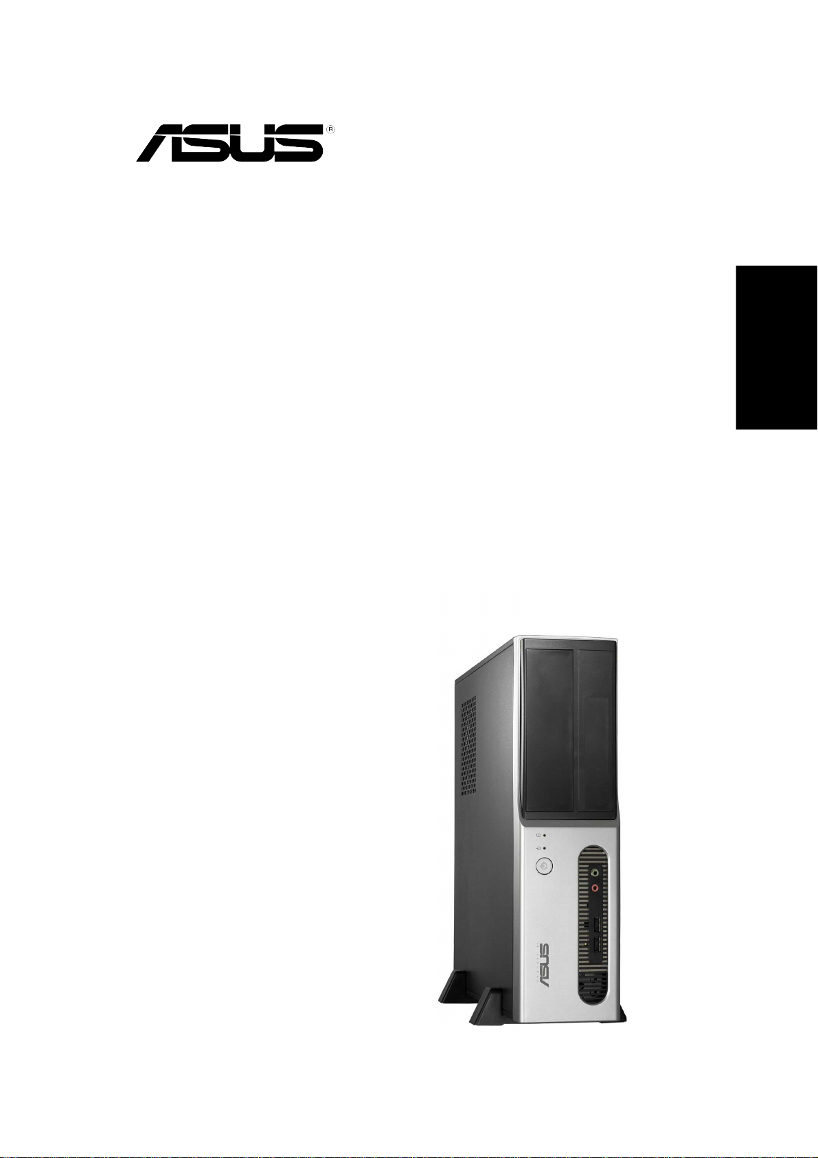
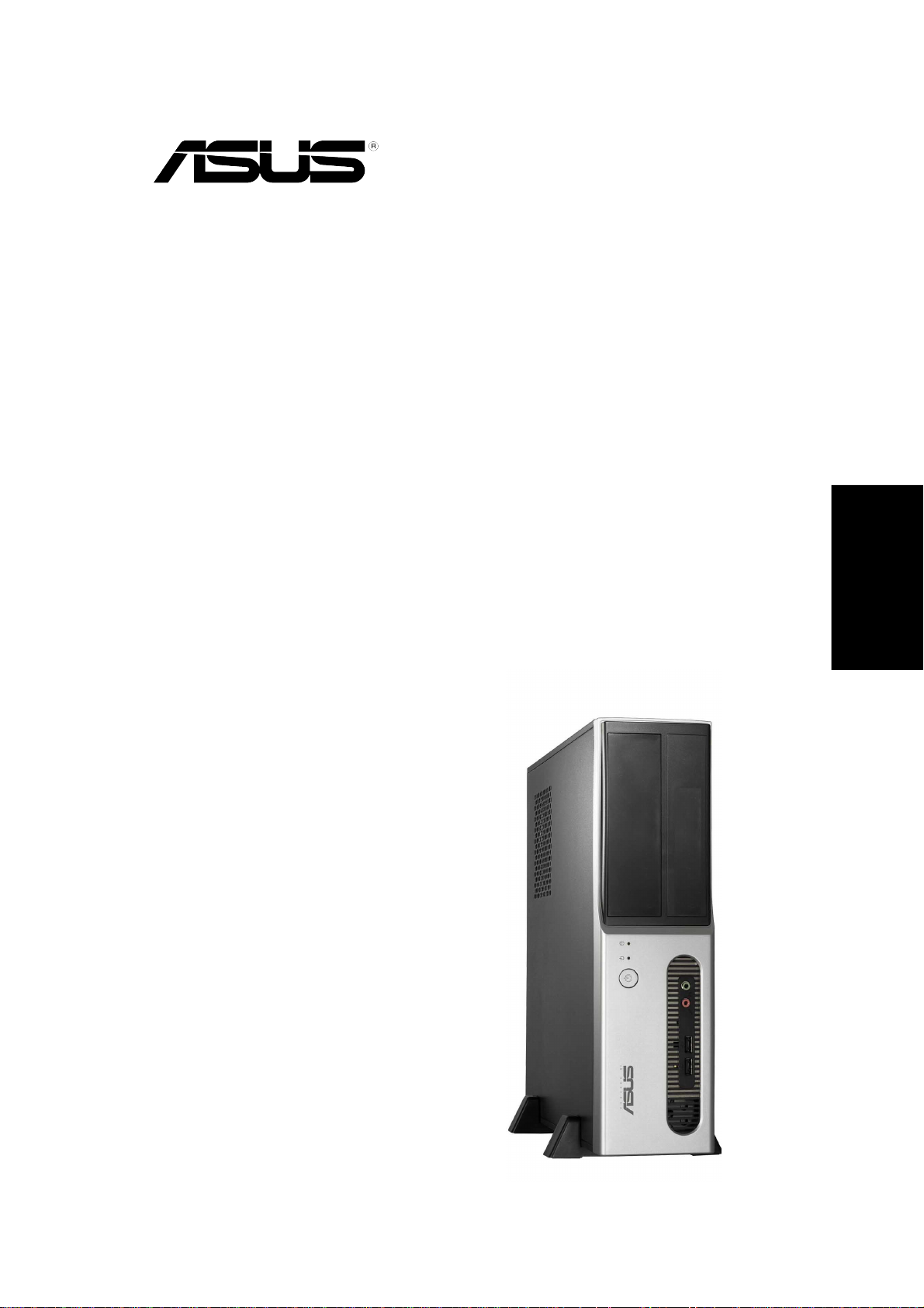
Page 1
Pundit-AE3
Barebone Systems
Quick Installation Guide
English
Page 2
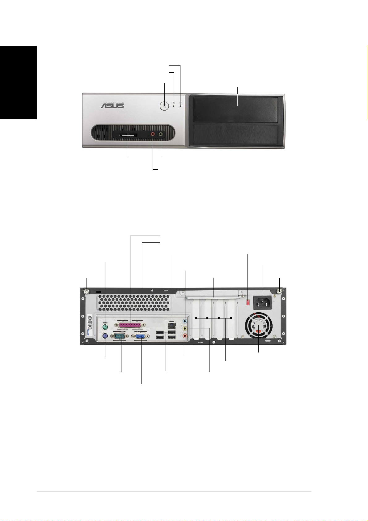
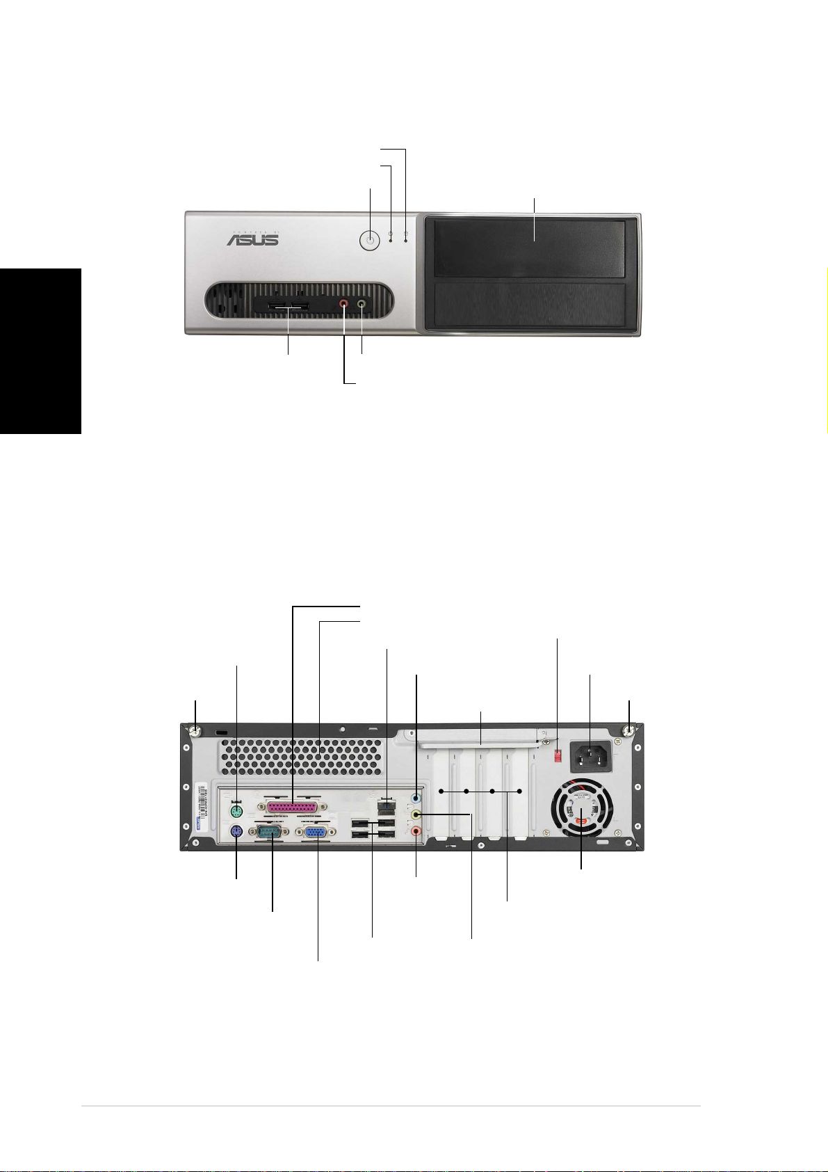
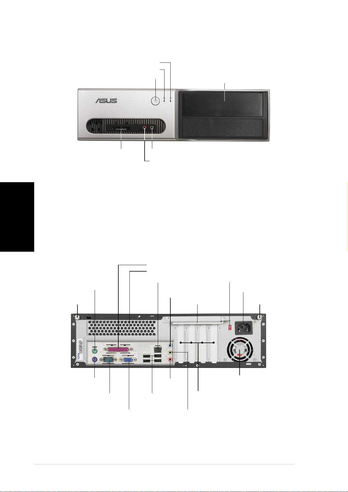
Front panel features
English
Rear panel features
Cover screwCover screw
Cover screw
Cover screwCover screw
Power buttonPower button
Power button
Power buttonPower button
USB 2.0 portsUSB 2.0 ports
USB 2.0 ports
USB 2.0 portsUSB 2.0 ports
PS/2 mouse portPS/2 mouse port
PS/2 mouse port
PS/2 mouse portPS/2 mouse port
HDD LEDHDD LED
HDD LED
HDD LEDHDD LED
Power LEDPower LED
Power LED
Power LEDPower LED
Microphone portMicrophone port
Microphone port
Microphone portMicrophone port
Headphone portHeadphone port
Headphone port
Headphone portHeadphone port
Parallel portParallel port
Parallel port
Parallel portParallel port
Air ventsAir vents
Air vents
Air ventsAir vents
LAN (RJ-45) portLAN (RJ-45) port
LAN (RJ-45) port
LAN (RJ-45) portLAN (RJ-45) port
5.25-inch drive bay cover5.25-inch drive bay cover
5.25-inch drive bay cover
5.25-inch drive bay cover5.25-inch drive bay cover
Voltage selectorVoltage selector
Voltage selector
Voltage selectorVoltage selector
Line In portLine In port
Line In port
Line In portLine In port
Metal bracket lockMetal bracket lock
Metal bracket lock
Metal bracket lockMetal bracket lock
Power connectorPower connector
Power connector
Power connectorPower connector
Cover screwCover screw
Cover screw
Cover screwCover screw
PS/2 keyboard portPS/2 keyboard port
PS/2 keyboard port
PS/2 keyboard portPS/2 keyboard port
22
2
22
Serial portSerial port
Serial port
Serial portSerial port
VGA portVGA port
VGA port
VGA portVGA port
Quick Installation GuideQuick Installation Guide
Quick Installation Guide
Quick Installation GuideQuick Installation Guide
Line OutLine Out
Line Out
Line OutLine Out
portport
port
portport
USB 2.0 portsUSB 2.0 ports
USB 2.0 ports
USB 2.0 portsUSB 2.0 ports
Power fan ventsPower fan vents
Power fan vents
Power fan ventsPower fan vents
PCI slot metal bracketsPCI slot metal brackets
PCI slot metal brackets
PCI slot metal bracketsPCI slot metal brackets
Microphone portMicrophone port
Microphone port
Microphone portMicrophone port
Page 3
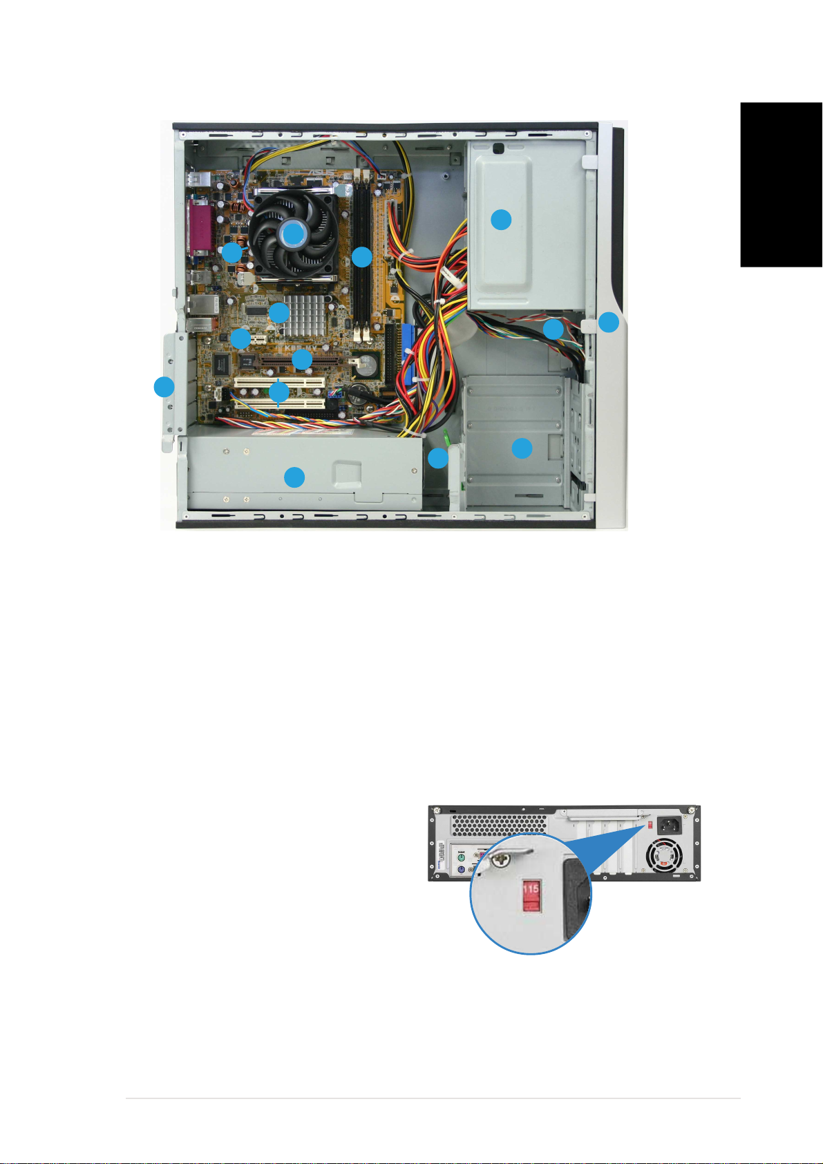
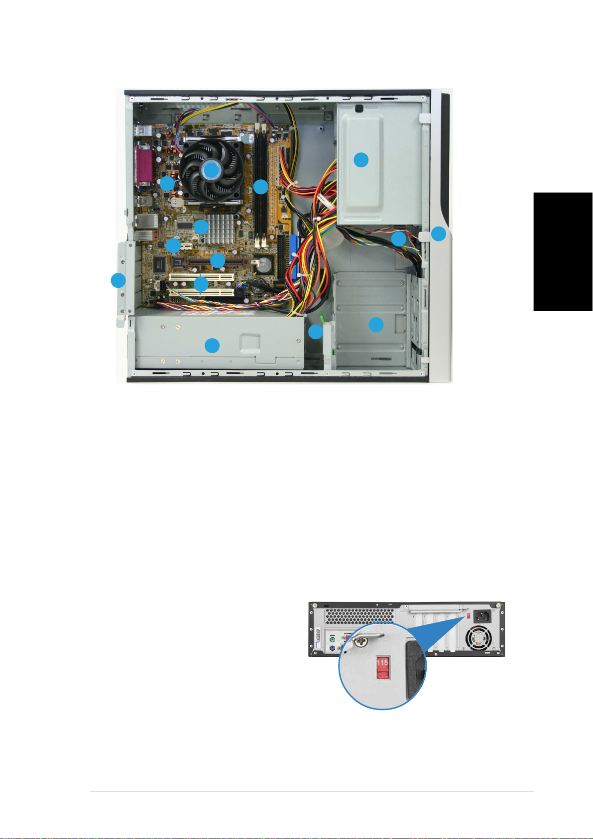
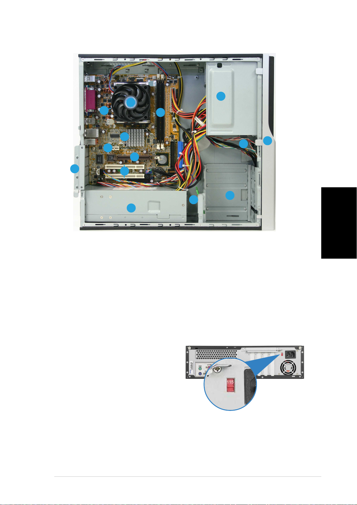
Internal components
11
33
1
3
11
33
11
22
1
2
11
22
1010
10
1010
77
7
77
99
9
99
11
11
1
1
11
11
88
8
88
66
6
66
1414
14
1414
1. 5.25-inch empty optical drive bay
2. Front panel cover
3. Optical drive lock
11
1
11
22
2
33
3
33
44
4
55
5
55
44
22
9. AGP slot
10. ASUS motherboard
11. Metal bracket lock
English
4. Hard disk drive bays
5. Hard disk drive lock
6. Power supply unit
7. PCI Express x1 slot
8. PCI slots
Selecting the voltage
The system’s power supply unit has
a 115 V/230 V voltage selector
switch located beside the power
connector. Use this switch to select
the appropriate system input voltage
according to the voltage supply in
your area.
If the voltage supply in your area is
100-127 V, set the switch to 115 V.
If the voltage supply in your area is
200-240 V, set the switch to 230 V.
12. CPU socket
(under the CPU fan
and heatsink assembly)
13. CPU fan and heatsink assembly
14. DIMM sockets
Quick Installation GuideQuick Installation Guide
Quick Installation Guide
Quick Installation GuideQuick Installation Guide
33
3
33
Page 4
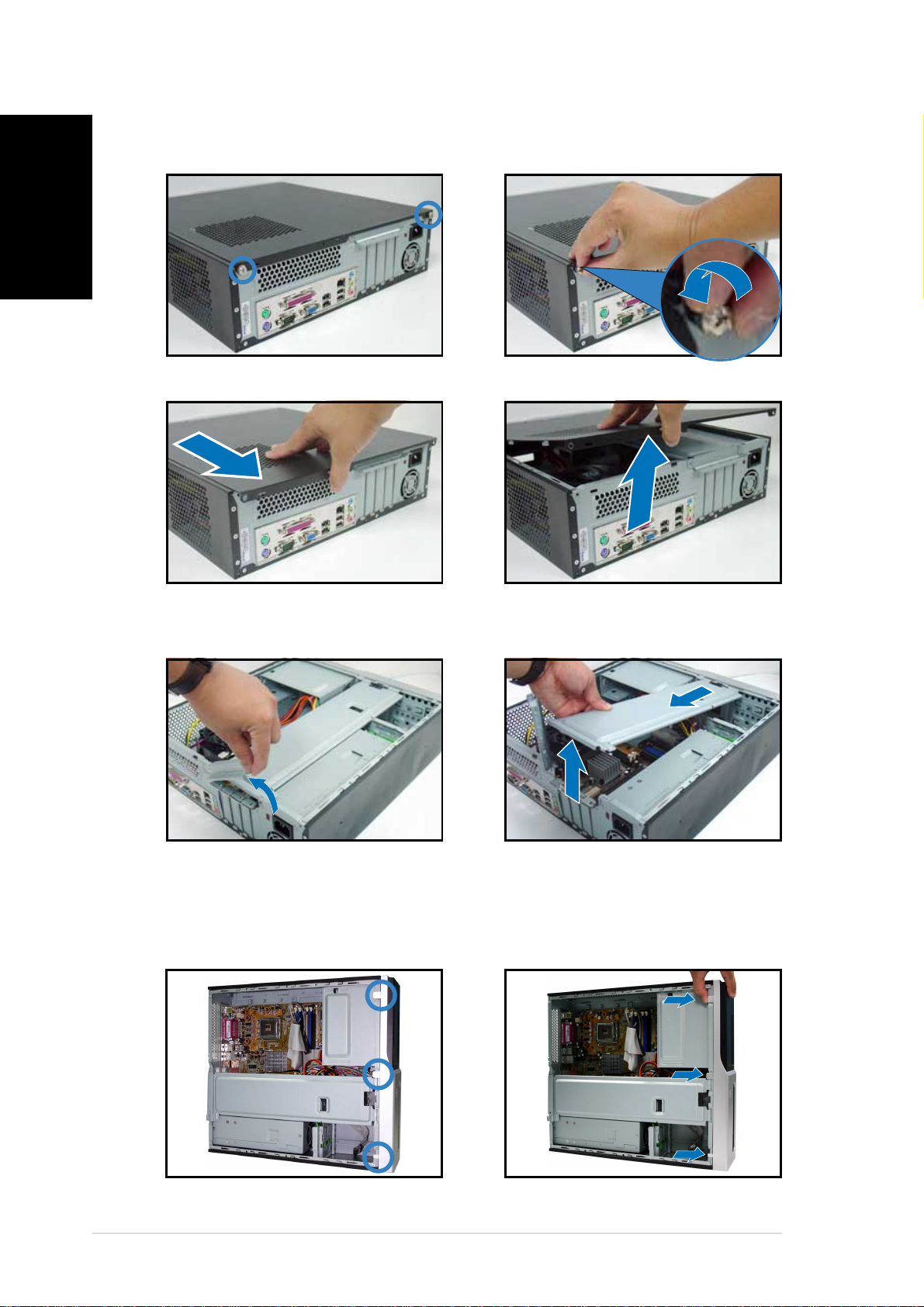
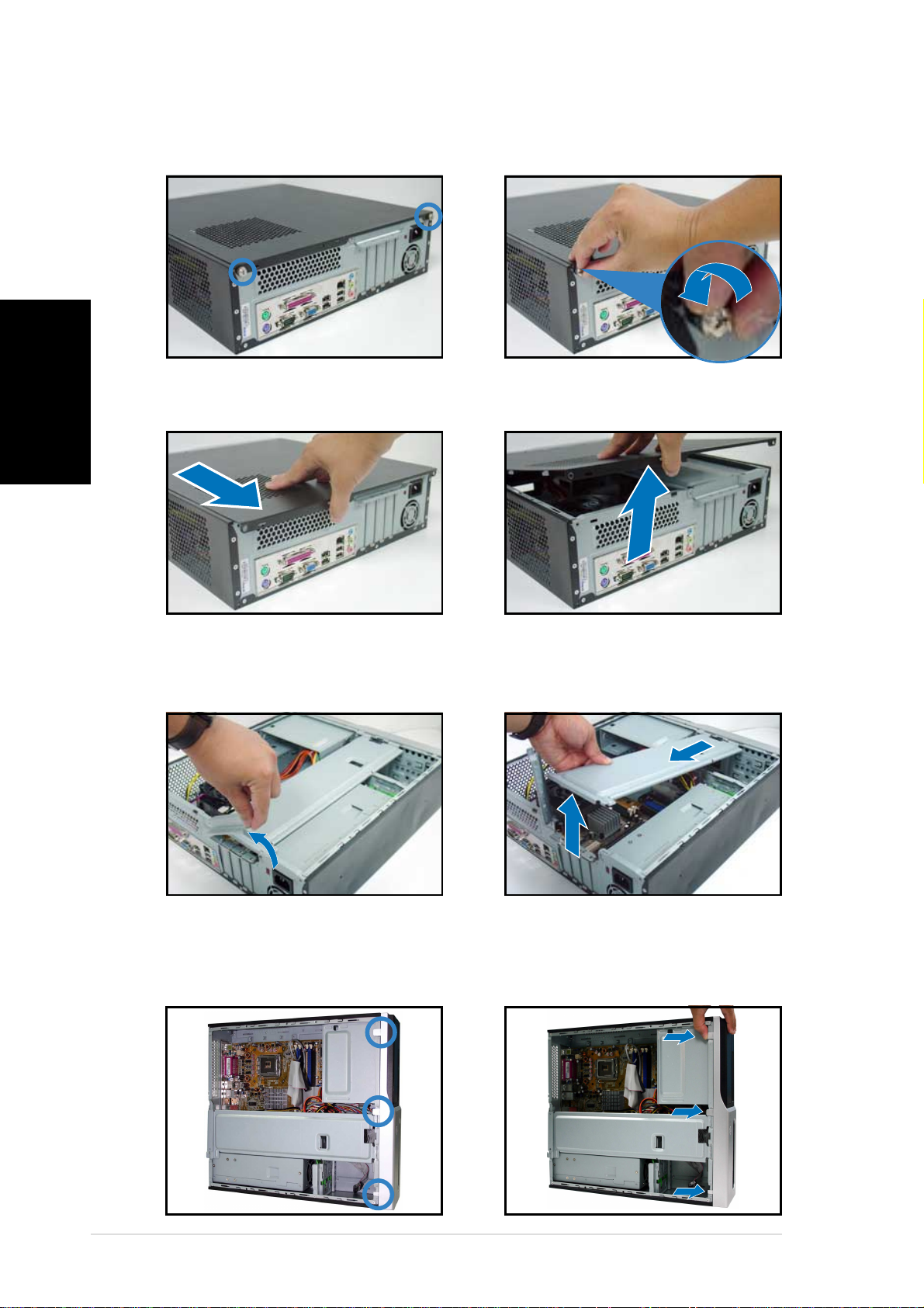
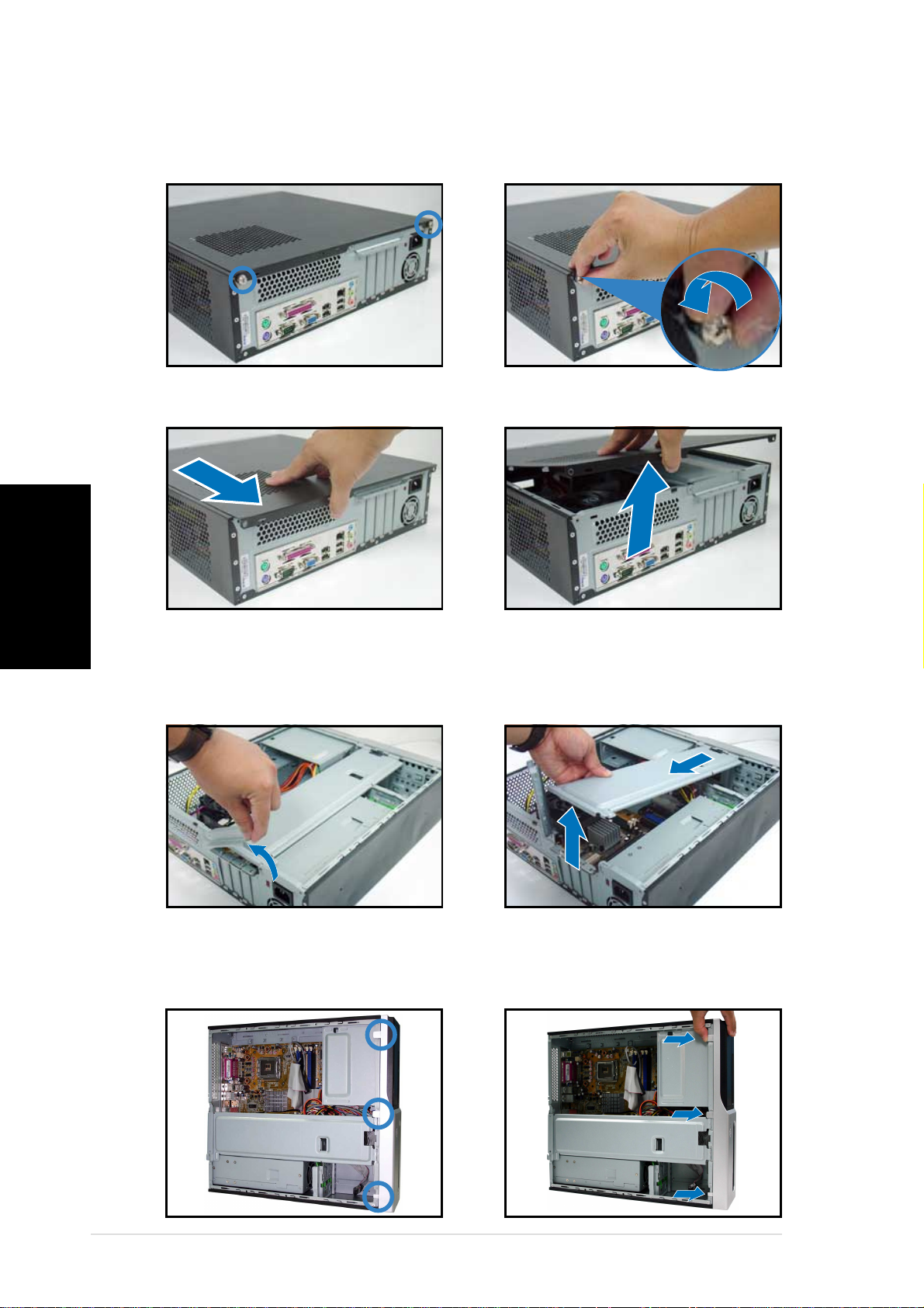
Removing the cover
English
1. Locate two cover screws.
3. Pull the cover.
2. Remove the cover screws.
4. Lift the cover, then set aside.
5. Lift the expansion card lock to
a 90º-100º angle.
6. Lift the chassis support
bracket, then remove.
Removing the front panel assembly
1. Locate the front panel
assembly hooks.
2. Pull the hooks outward to
remove.
44
4
44
Quick Installation GuideQuick Installation Guide
Quick Installation Guide
Quick Installation GuideQuick Installation Guide
Page 5
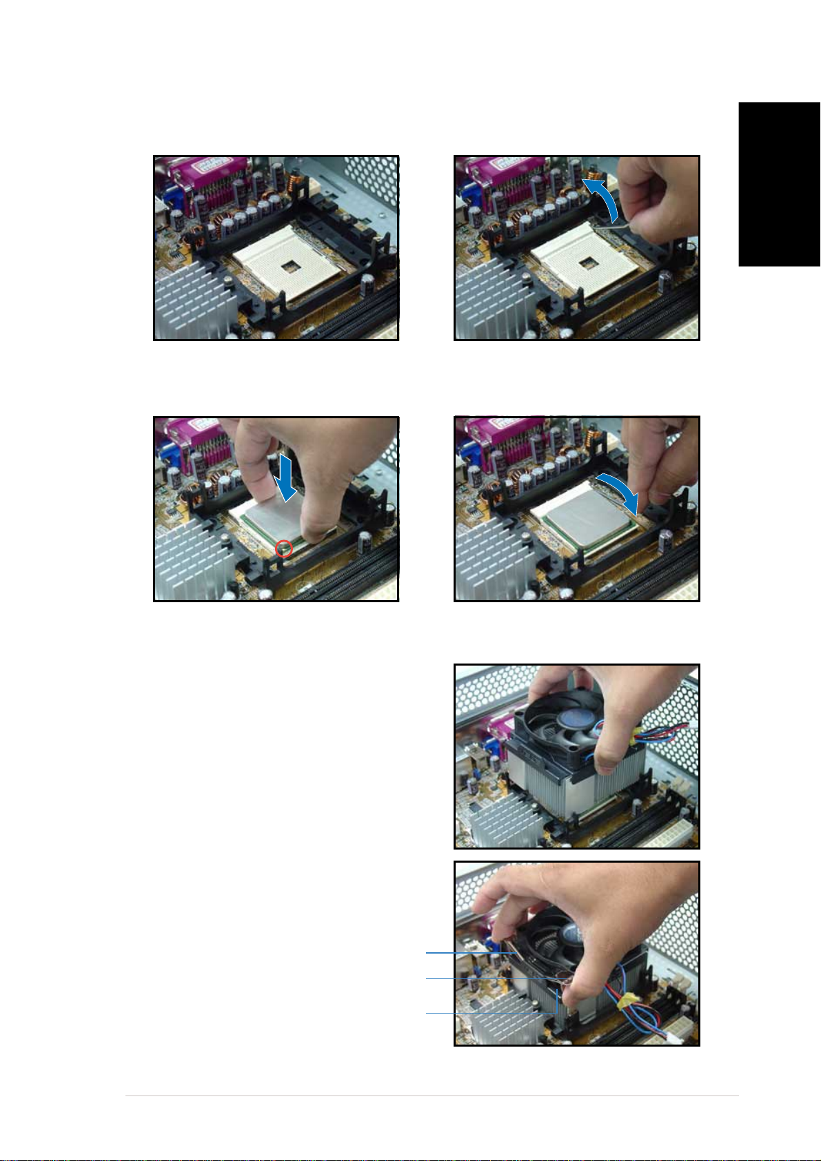
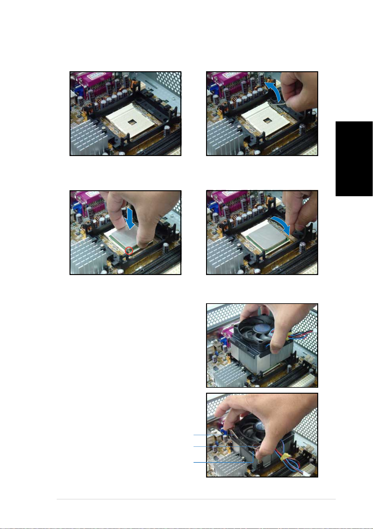
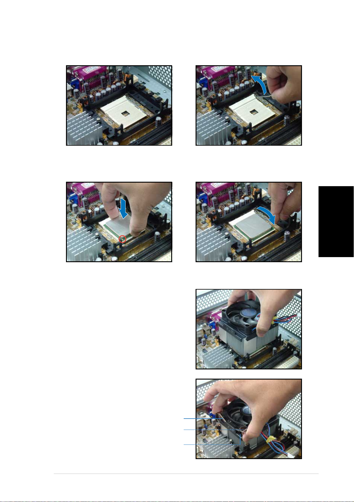
Installing a CPU
2. Unlock the socket.1. Locate the CPU socket.
English
3. Insert the CPU to the socket.
4. Push down the socket lever to
secure the CPU.
Installing the CPU fan and heatsink assemblyInstalling the CPU fan and heatsink assembly
Installing the CPU fan and heatsink assembly
Installing the CPU fan and heatsink assemblyInstalling the CPU fan and heatsink assembly
1. Position the CPU fan and
heatsink assembly on top of
the CPU.
2. Align the retention clip with the
rails on the side of the CPU fan.
Retention clipRetention clip
Retention clip
Retention clipRetention clip
Locking leverLocking lever
Locking lever
Locking leverLocking lever
CPU fan side railsCPU fan side rails
CPU fan side rails
CPU fan side railsCPU fan side rails
Quick Installation GuideQuick Installation Guide
Quick Installation Guide
Quick Installation GuideQuick Installation Guide
55
5
55
Page 6
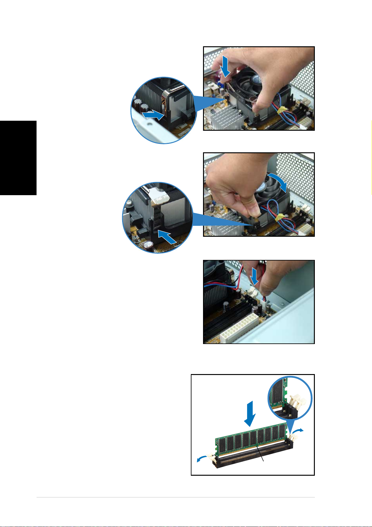
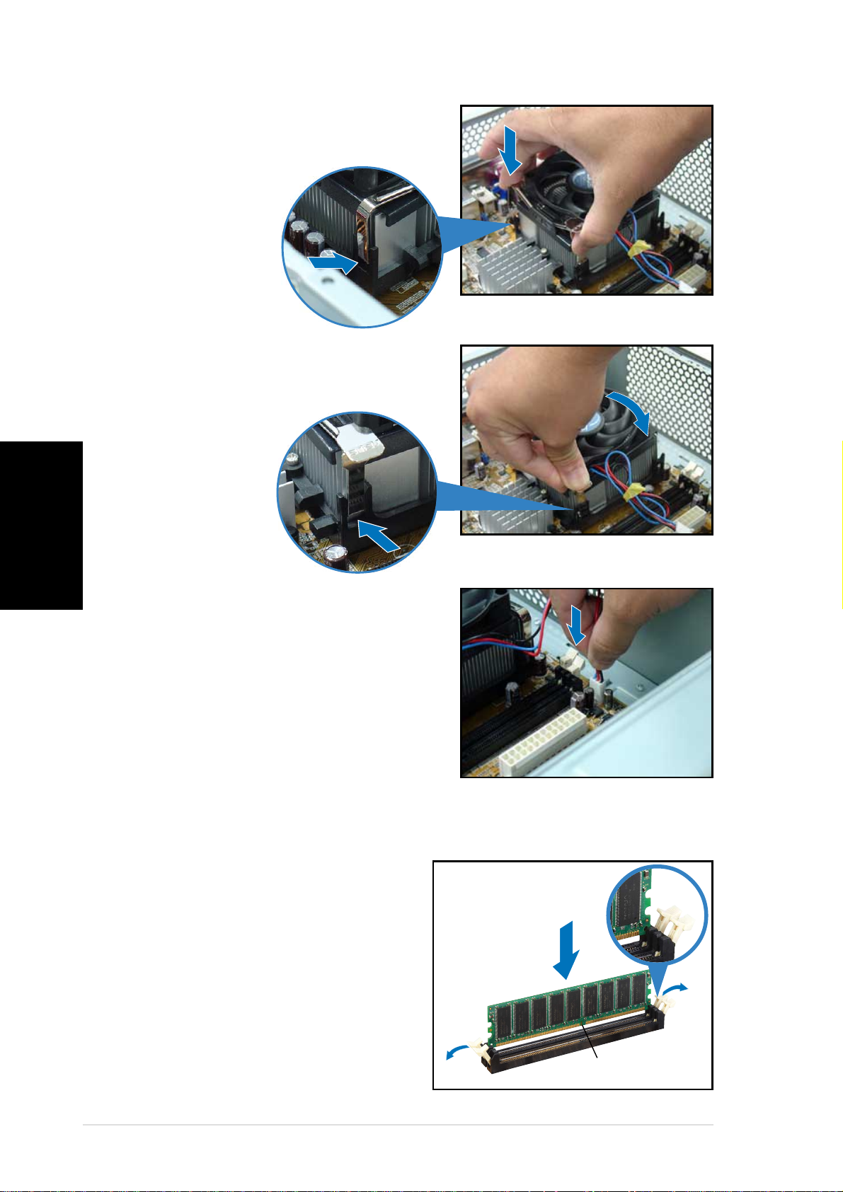
3. Insert one retention clip hook to
English
4. Carefully press down the retention
the hole at the other side of the
retention module.
clip locking lever until the hook
attaches to retention module
hole.
5. Install the second retention clip.
Make sure that the retention clip
locking levers are on opposite
corners of the CPU fan.
6. Connect the CPU fan cable to the
CPU fan connector on the
motherboard.
Installing a DIMM
1. Locate the DIMM sockets in the
motherboard.
2. Unlock a DIMM socket by
pressing the retaining clips
outward.
3. Align a DIMM on the socket such
that the notch on the DIMM
matches the break on the
socket.
UnlockedUnlocked
Unlocked
UnlockedUnlocked
retaining clipretaining clip
retaining clip
retaining clipretaining clip
DDR DIMM notchDDR DIMM notch
DDR DIMM notch
DDR DIMM notchDDR DIMM notch
66
6
66
Quick Installation GuideQuick Installation Guide
Quick Installation Guide
Quick Installation GuideQuick Installation Guide
Page 7
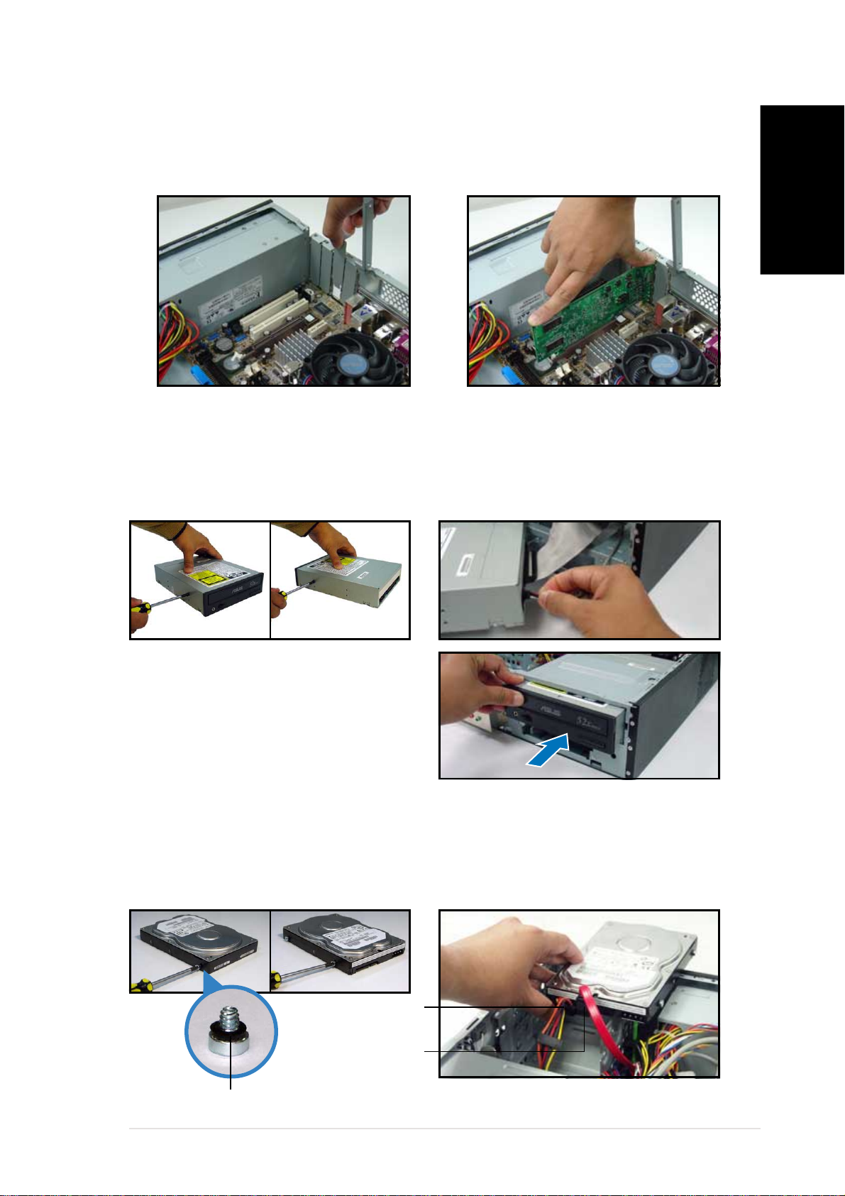
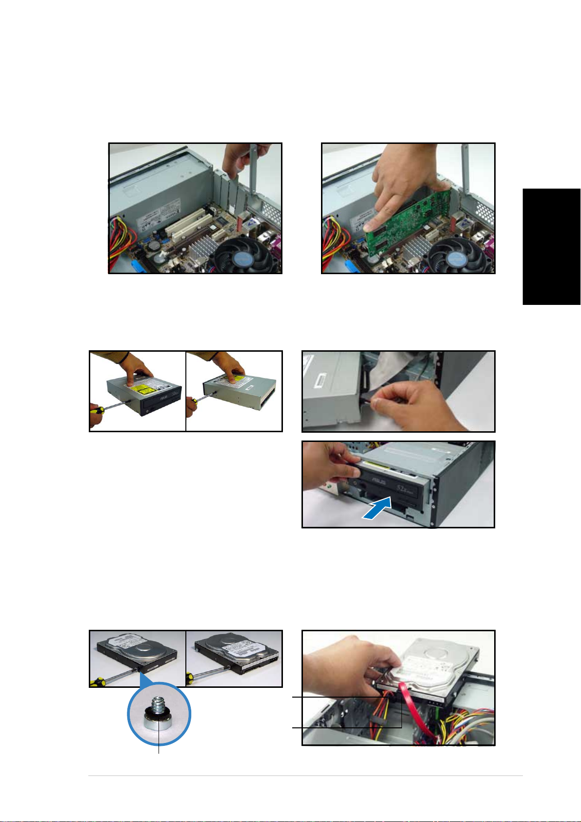
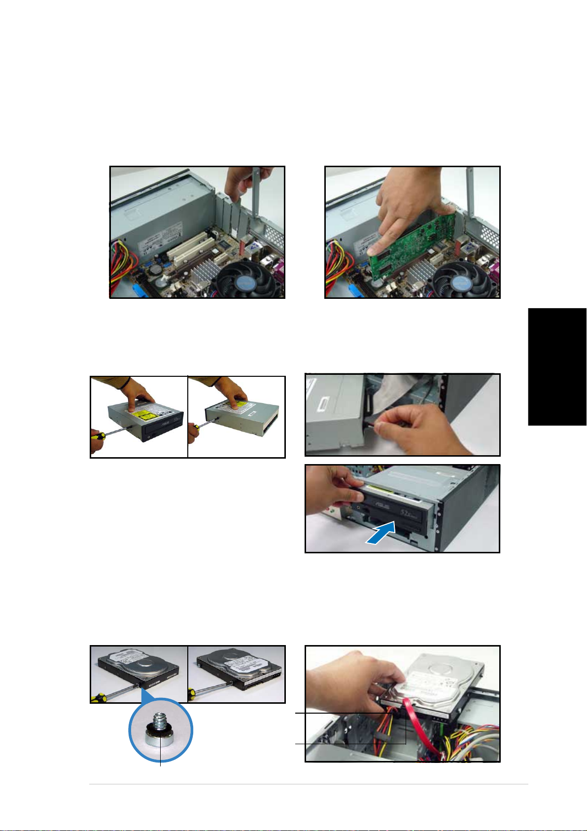
Installing an expansion card
1. Remove the metal cover
opposite the slot that you
intend to use.
2. Insert the card connector to
the slot, then press the card
firmly until it fits in place.
Installing an optical drive
1. Drive a screw on the top right
screw hole on both sides of
the drive.
2. Connect the IDE and audio
cable at the back of the drive.
English
3. Push the drive all the way into
the bay until the drive lock clicks.
4. Connect a 4-pin power plug
from the power supply unit to
the power connector at the
back of the drive.
Installing a SATA hard disk drive
1. Drive two screws with rubber
washers on both sides of the
drive.
Power cablePower cable
Power cable
Power cablePower cable
and plugand plug
and plug
and plugand plug
Signal cableSignal cable
Signal cable
Signal cableSignal cable
and plugand plug
and plug
and plugand plug
2. Connect the SATA signal and
power plug at the back of the
drive.
Rubber washerRubber washer
Rubber washer
Rubber washerRubber washer
Quick Installation GuideQuick Installation Guide
Quick Installation Guide
Quick Installation GuideQuick Installation Guide
77
7
77
Page 8
English
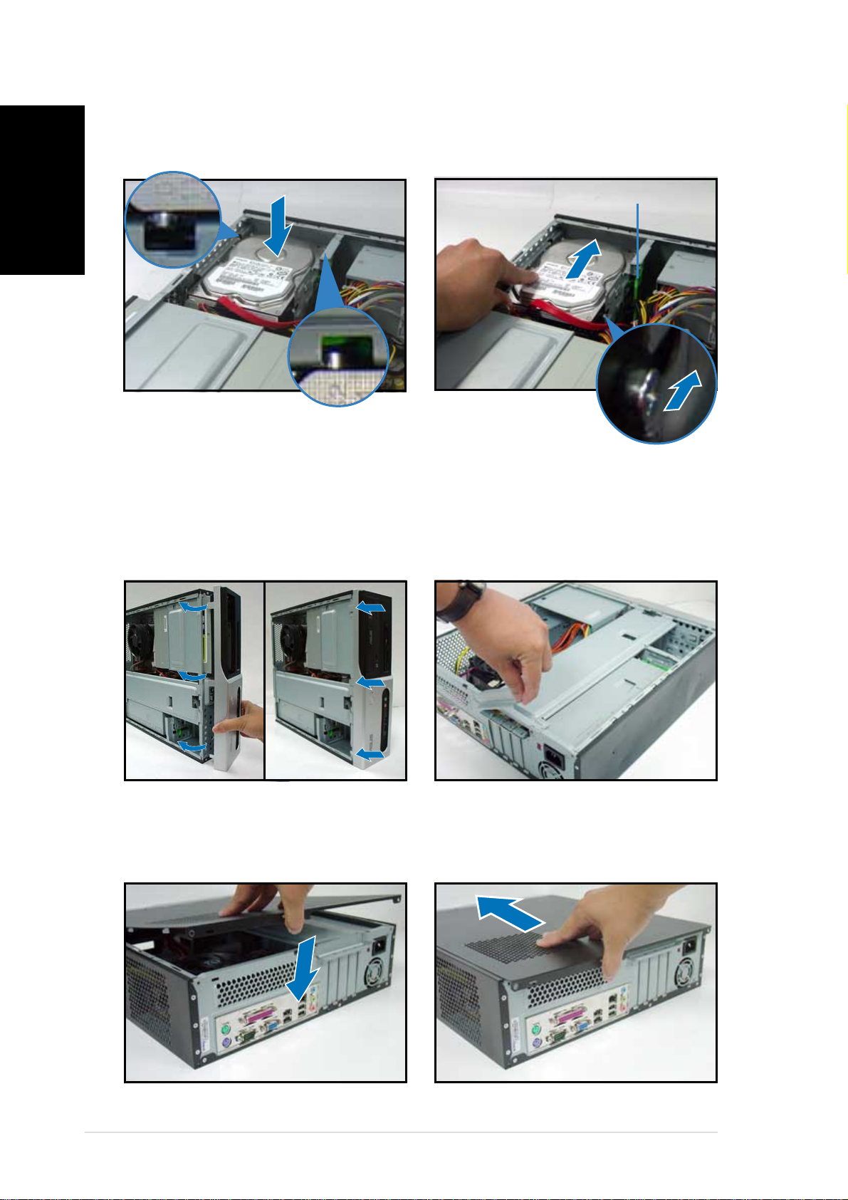
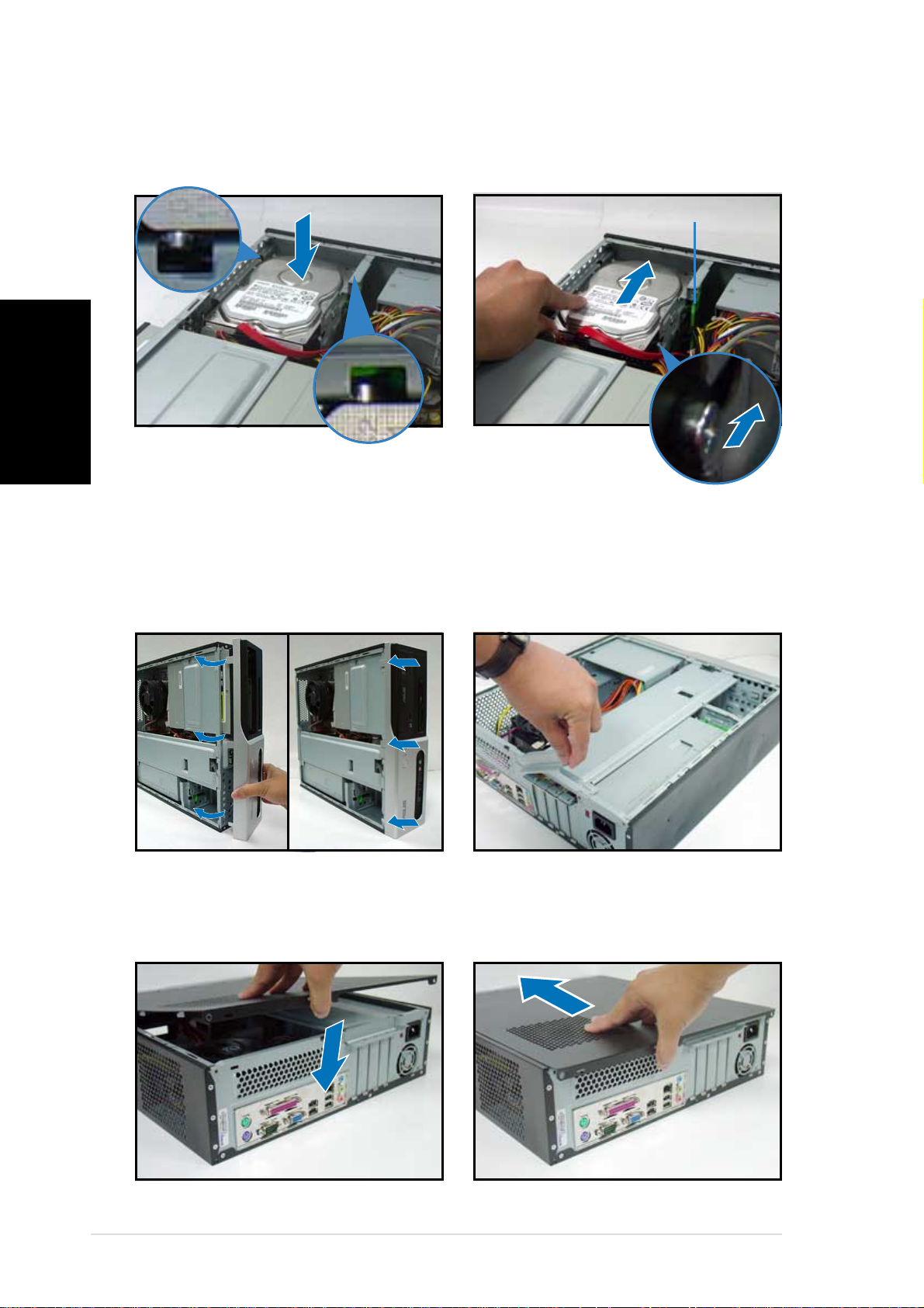
3. Place the HDD on the tray. 4. When the HDD screws align,
Replacing the covers
push the drive on the bay.
HDD screw lockHDD screw lock
HDD screw lock
HDD screw lockHDD screw lock
1. Replace the front panel
assembly. Remove the 5.25”
drive bay cover when you
installed an optical drive.
3. Insert the cover hooks to the
holes on the chassis side.
2. Reinstall the metal chassis
support and the expansion
card lock.
4. Push the cover to the direction
of the front panel, then
replace the cover screws.
88
8
88
Quick Installation GuideQuick Installation Guide
Quick Installation Guide
Quick Installation GuideQuick Installation Guide
Page 9
Pundit-AE3
Système barebone
Guide de démarrage rapide
Français
Page 10
Français
Caractéristiques de la façade
LED HDDLED HDD
LED HDD
LED HDDLED HDD
LED d’ alimentationLED d’ alimentation
LED d’ alimentation
LED d’ alimentationLED d’ alimentation
Bouton d’ alimentationBouton d’ alimentation
Bouton d’ alimentation
Bouton d’ alimentationBouton d’ alimentation
Cache de baie 5.25 poucesCache de baie 5.25 pouces
Cache de baie 5.25 pouces
Cache de baie 5.25 poucesCache de baie 5.25 pouces
Ports USB 2.0Ports USB 2.0
Ports USB 2.0
Ports USB 2.0Ports USB 2.0
Port MicrophonePort Microphone
Port Microphone
Port MicrophonePort Microphone
Port CasquePort Casque
Port Casque
Port CasquePort Casque
Caractéristiques de l’arrière
Port parallè lePort parallèle
Port parallè le
Port parallè lePort parallèle
A é rationsA é rations
A é rations
A é rationsA é rations
Port LAN (RJ-45)Port LAN (RJ-45)
Port LAN (RJ-45)
Port LAN (RJ-45)Port LAN (RJ-45)
Port souris PS/2Port souris PS/2
Port souris PS/2
Port souris PS/2Port souris PS/2
Vis du capotVis du capot
Vis du capot
Vis du capotVis du capot
Port Line InPort Line In
Port Line In
Port Line InPort Line In
Verrouillage desVerrouillage des
Verrouillage des
Verrouillage desVerrouillage des
brackets mé talliquesbrackets métalliques
brackets mé talliques
brackets mé talliquesbrackets métalliques
S é lecteur de tensionS é lecteur de tension
S é lecteur de tension
S é lecteur de tensionS é lecteur de tension
ConnecteurConnecteur
Connecteur
ConnecteurConnecteur
d ’ alimentationd ’ alimentation
d ’ alimentation
d ’ alimentationd ’ alimentation
Vis du capotVis du capot
Vis du capot
Vis du capotVis du capot
Port clavier PS/2Port clavier PS/2
Port clavier PS/2
Port clavier PS/2Port clavier PS/2
22
2
22
Port Sé riePort Sé rie
Port Sé rie
Port Sé riePort Sé rie
Port VGAPort VGA
Port VGA
Port VGAPort VGA
Guide de dé marrage rapideGuide de dé marrage rapide
Guide de dé marrage rapide
Guide de dé marrage rapideGuide de dé marrage rapide
Port LinePort Line
Port Line
Port LinePort Line
OutOut
Out
OutOut
Ports USB 2.0Ports USB 2.0
Ports USB 2.0
Ports USB 2.0Ports USB 2.0
A é rationA é ration
A é ration
A é rationA é ration
d ’ alimentationd ’ alimentation
d ’ alimentation
d ’ alimentationd ’ alimentation
Brackets mé talliquesBrackets mé talliques
Brackets mé talliques
Brackets mé talliquesBrackets mé talliques
des ports PCIdes ports PCI
des ports PCI
des ports PCIdes ports PCI
Port MicrophonePort Microphone
Port Microphone
Port MicrophonePort Microphone
Page 11
Composants internes
11
33
1
3
11
33
11
22
1
2
11
22
1010
10
1010
77
7
77
99
9
99
1414
14
1414
11
1
11
22
2
33
3
33
22
11
11
1
1
11
11
1. Baie 5.25 pouces vide
2. Façade
3. Verrouillage du lecteur optique
88
8
88
66
6
66
9. Slot AGP
10. Carte mère ASUS
11. Verrouillage des brackets
4. Baies pour disques durs
5. Verrouillage du disque dur
12. Socket CPU
6. Alimentation
7. Slot PCI Express x1
8. Slots PCI
13. Système de refroidissement du
14. Sockets DIMM
44
4
55
5
55
44
métalliques
(sous le système de
refroidissement du CPU)
CPU
Français
Choisir le voltage
L’alimentation du système est
équipée d’un sélecteur de tension
115 V/230 V situé près du
connecteur d’alimentation. Utilisez
cet interrupteur pour choisir la bonne
tension d’entrée en fonction des
standards utilisés dans votre région.
Si la tension dans votre région est de
100-127 V, passez l’interrupteur sur 115 V.
Si la tension dans votre région est de 200-240 V, passez l’interrupteur sur
230 V.
Guide de dé marrage rapideGuide de dé marrage rapide
Guide de dé marrage rapide
Guide de dé marrage rapideGuide de dé marrage rapide
33
3
33
Page 12
Enlever le capot
Français
1. Localisez les deux vis.
3. Tirez le capot.
2. Enlevez les deux vis.
4. Soulevez le capot, puis
basculez-le.
5. Levez le verrou pour cartes
d’extension à un angle de 90º100º.
Enlever la façade
1. Localisez les crochets de la
façade.
6. Soulevez le support de
brackets puis enlevez-le.
2. Tirez les crochets vers
l’extérieur.
44
4
44
Guide de dé marrage rapideGuide de dé marrage rapide
Guide de dé marrage rapide
Guide de dé marrage rapideGuide de dé marrage rapide
Page 13
Installer un CPU
2. Déverrouillez le socket.1. Localisez le socket du CPU.
3. Insérez le CPU dans le socket
4. Rabaissez le levier pour verrouiller le CPU dans le socket.
Installer le radiateur et le ventilateur du CPUInstaller le radiateur et le ventilateur du CPU
Installer le radiateur et le ventilateur du CPU
Installer le radiateur et le ventilateur du CPUInstaller le radiateur et le ventilateur du CPU
1. Positionnez l’ensemble
dissipateur-ventilateur sur le
CPU.
Français
2. Alignez le clip de rétention avec
les rails sur le côté du ventilateur
du CPU.
Clip de ré tentionClip de ré tention
Clip de ré tention
Clip de ré tentionClip de ré tention
Levier deLevier de
Levier de
Levier deLevier de
verrouillageverrouillage
verrouillage
verrouillageverrouillage
Rails laté raux duRails laté raux du
Rails laté raux du
Rails laté raux duRails laté raux du
ventilateur CPUventilateur CPU
ventilateur CPU
ventilateur CPUventilateur CPU
Guide de dé marrage rapideGuide de dé marrage rapide
Guide de dé marrage rapide
Guide de dé marrage rapideGuide de dé marrage rapide
55
5
55
Page 14
Français
3. Insérez un crochet d’un clip de
rétentiondans un trou de l’autre
côté du module de rétention.
4. Poussez vers le bas avec
précaution le levier de verrouillage
jusqu’à ce que les crochets se
fixent aux trous
du module de
rétention.
5. Installez le second clip de
rétention. Assurez-vous que les
leviers de verrouillage pointent
vers des coins opposés du
ventilateur du CPU.
6. Connectez le câble du ventilateur
du CPU à la carte mère.
Installer un module DIMM
1. Localisez les sockets DIMM de la
carte mère.
2. Déverrouillez un socket DIMM en
pressant sur les clips de
rétention vers l’extérieur.
3. Alignez un module DIMM sur le
socket de sorte que l’encoche
sur la DIMM corresponde à
l’ergot du socket.
Clip de ré tentionClip de ré tention
Clip de ré tention
Clip de ré tentionClip de ré tention
d é verrouilléd é verrouillé
d é verrouillé
d é verrouilléd é verrouillé
Encoche du DIMM DDREncoche du DIMM DDR
Encoche du DIMM DDR
Encoche du DIMM DDREncoche du DIMM DDR
66
6
66
Guide de dé marrage rapideGuide de dé marrage rapide
Guide de dé marrage rapide
Guide de dé marrage rapideGuide de dé marrage rapide
Page 15
Installer une carte d’extension
1. Enlevez la protection
métallique du slot que vous
voulez utiliser.
2. Insérez le connecteur de la
carte dans le slot et pressez
jusqu’à ce que la carte soit en
place.
Installer un lecteur optique
1. Mettez une vis dans le pas de
vis en haut à droite de chaque
côté du lecteur.
2. Connectez les câbles IDE et
audio à l’arrière du lecteur.
Français
3. Enfoncez le lecteur dans la baie
jusqu’à ce que les verrous cliquent.
4. Branchez une prise
d’alimentation 4 broches de
l’alimentation dans le
connecteur d’alimentation à
l’arrière du lecteur.
Installer un disque dur SATA
1. Mettez deux vis avec joint de
caoutchouc de chaque côté du
lecteur.
C â ble et priseC â ble et prise
C â ble et prise
C â ble et priseC â ble et prise
d ’ alimentationd ’ alimentation
d ’ alimentation
d ’ alimentationd ’ alimentation
C â ble et priseC â ble et prise
C â ble et prise
C â ble et priseC â ble et prise
de signalde signal
de signal
de signalde signal
2. Connectez les câbles de signal
et d’alimentation à l’arrière du
disque.
Joint de caoutchoucJoint de caoutchouc
Joint de caoutchouc
Joint de caoutchoucJoint de caoutchouc
Guide de dé marrage rapideGuide de dé marrage rapide
Guide de dé marrage rapide
Guide de dé marrage rapideGuide de dé marrage rapide
77
7
77
Page 16
Français
3. Placez le disque dur sur le
plateau.
Refermer la machine
4. Quand les vis du disque sont
alignées, poussez-le dans la
baie.
Verrou des vis HDDVerrou des vis HDD
Verrou des vis HDD
Verrou des vis HDDVerrou des vis HDD
1. Replacez la façade. Enlevez le
cache de la baie 5.25” si vous
avez installé un lecteur
optique.
3. Insérez les crochets dans les
trous de chaque côté du
châssis.
2. Réinstallez le support de
châssis métallique et le
verrouillage des cartes
d’extension.
4. Poussez la plaque vers la
façade, puis revissez le
panneau.
88
8
88
Guide de dé marrage rapideGuide de dé marrage rapide
Guide de dé marrage rapide
Guide de dé marrage rapideGuide de dé marrage rapide
Page 17
Pundit-AE3
Barebone Systeme
Schnellinstallationsanleitung
Deutsch
Page 18
Frontseite
HDD-LEDHDD-LED
HDD-LED
HDD-LEDHDD-LED
Betriebs-LEDBetriebs-LED
Betriebs-LED
Betriebs-LEDBetriebs-LED
StromschalterStromschalter
Stromschalter
StromschalterStromschalter
Blende des 5,25-ZollBlende des 5,25-Zoll
Blende des 5,25-Zoll
Blende des 5,25-ZollBlende des 5,25-Zoll
LaufwerkfachsLaufwerkfachs
Laufwerkfachs
LaufwerkfachsLaufwerkfachs
USB 2.0-Anschlü sseUSB 2.0-Anschlü sse
USB 2.0-Anschlü sse
USB 2.0-Anschlü sseUSB 2.0-Anschlü sse
Deutsch
Rückseite
MausanschlussMausanschluss
Mausanschluss
MausanschlussMausanschluss
AbdeckungsschraubeAbdeckungsschraube
Abdeckungsschraube
AbdeckungsschraubeAbdeckungsschraube
PS/2-PS/2-
PS/2-
PS/2-PS/2-
MikrofonanschlussMikrofonanschluss
Mikrofonanschluss
MikrofonanschlussMikrofonanschluss
Kopfhö reranschlussKopfhöreranschluss
Kopfhö reranschluss
Kopfhö reranschlussKopfhöreranschluss
Paralleler AnschlussParalleler Anschluss
Paralleler Anschluss
Paralleler AnschlussParalleler Anschluss
L ü ftungsö ffnungenL ü ftungsö ffnungen
L ü ftungsö ffnungen
L ü ftungsö ffnungenL ü ftungsö ffnungen
LAN (RJ-45)-AnschlussLAN (RJ-45)-Anschluss
LAN (RJ-45)-Anschluss
LAN (RJ-45)-AnschlussLAN (RJ-45)-Anschluss
Line In-AnschlussLine In-Anschluss
Line In-Anschluss
Line In-AnschlussLine In-Anschluss
MetallblendenriegelMetallblendenriegel
Metallblendenriegel
MetallblendenriegelMetallblendenriegel
SpannungsschalterSpannungsschalter
Spannungsschalter
SpannungsschalterSpannungsschalter
StromanschlussStromanschluss
Stromanschluss
StromanschlussStromanschluss
AbdeckungsschraubeAbdeckungsschraube
Abdeckungsschraube
AbdeckungsschraubeAbdeckungsschraube
TastaturanschlussTastaturanschluss
Tastaturanschluss
TastaturanschlussTastaturanschluss
Serieller AnschlussSerieller Anschluss
Serieller Anschluss
Serieller AnschlussSerieller Anschluss
22
2
22
PS/2-PS/2-
PS/2-
PS/2-PS/2-
Line Out-Line Out-
Line Out-
Line Out-Line OutAnschlussAnschluss
Anschluss
AnschlussAnschluss
PCI-Steckplatz-PCI-Steckplatz-
PCI-Steckplatz-
USB 2.0-USB 2.0-
USB 2.0-
USB 2.0-USB 2.0Anschlü sseAnschlü sse
Anschlü sse
Anschlü sseAnschlü sse
VGA-AnschlussVGA-Anschluss
VGA-Anschluss
VGA-AnschlussVGA-Anschluss
SchnellinstallationsanleitungSchnellinstallationsanleitung
Schnellinstallationsanleitung
SchnellinstallationsanleitungSchnellinstallationsanleitung
PCI-Steckplatz-PCI-SteckplatzMetallblendenMetallblenden
Metallblenden
MetallblendenMetallblenden
MikrofonanschlussMikrofonanschluss
Mikrofonanschluss
MikrofonanschlussMikrofonanschluss
Netzteilgeblä se-Netzteilgebläse-
Netzteilgeblä se-
Netzteilgeblä se-NetzteilgebläseL ü ftungsö ffnungenL ü ftungsö ffnungen
L ü ftungsö ffnungen
L ü ftungsö ffnungenL ü ftungsö ffnungen
Page 19
Interne Komponenten
11
33
1
3
11
33
11
22
1
2
11
22
1010
10
1010
77
7
77
99
9
99
11
11
1
1
11
11
88
8
88
66
6
66
1414
14
1414
11
1
11
22
2
33
3
33
44
4
55
5
55
44
22
1. Leeres 5,25-Zoll Fach für ein
optisches Laufwerk
2. Fronttafelabdeckung
3. Riegel des optischen
Laufwerks
4. Festplattenfach
5. Riegel des Festplattenfachs
6. Netzteil
8. PCI-Steckplätze
9. AGP-Steckplätze
10. ASUS-Motherboard
11. Metallblendenriegel
12. CPU-Sockel
Lüfter-Kühlkörper-Einheit)
13. CPU-Lüfter-Kühlkörper-Einheit
14. DIMM-Steckplätze
7. PCI Express x1-Steckplatz
Auswählen der Netzspannung
Das Netzteil ist mit einem 115V/
230V-Spannungsschalter neben dem
Stromanschluss ausgestattet.
Verwenden Sie diesen Schalter, um
die passende
Systemeingangsspannung
entsprechend Ihrem
Stromversorgungssystem in Ihrer
Region auszuwählen.
Deutsch
(unter der CPU-
Stellen Sie den Schalter auf 115V, wenn die Stromversorgung in Ihrer
Region 100V bis 127V ist.
Stellen Sie den Schalter auf 230V, wenn die Stromversorgung in Ihrer
Region 200V bis 240V ist.
SchnellinstallationsanleitungSchnellinstallationsanleitung
Schnellinstallationsanleitung
SchnellinstallationsanleitungSchnellinstallationsanleitung
33
3
33
Page 20
Entfernen der Abdeckung
1. Suchen Sie die zwei
3. Ziehen Sie die Abdeckung.
Deutsch
Abdeckungsschrauben.
2. Entfernen Sie die
Abdeckungsschrauben.
4. Heben Sie die Abdeckung und
legen sie zur Seite.
5. Ziehen Sie den
Erweiterungssteckplatzriegel
bis zu einem Winkel von 90°-
100° hoch.
6. Heben Sie das
Gehäusestützblech, um es zu
entfernen.
Entfernen der Fronttafeleinheit
1. Suchen Sie die
Fronttafeleinheitshaken.
2. Ziehen Sie die Haken nach außen,
um die Einheit zu entfernen.
44
4
44
SchnellinstallationsanleitungSchnellinstallationsanleitung
Schnellinstallationsanleitung
SchnellinstallationsanleitungSchnellinstallationsanleitung
Page 21
Installieren einer CPU
2. Entriegeln Sie den Sockel.1. Suchen Sie den CPU-Sockel.
3. Stecken Sie die CPU in den
Sockel ein.
4. Drücken Sie den Sockelhebel
nach unten, um die CPU zu
arretieren.
Installieren der CPU-Lüfter-Kühlkörper-EinheitInstallieren der CPU-Lüfter-Kühlkörper-Einheit
Installieren der CPU-Lüfter-Kühlkörper-Einheit
Installieren der CPU-Lüfter-Kühlkörper-EinheitInstallieren der CPU-Lüfter-Kühlkörper-Einheit
1. Legen Sie die CPU-Lüfter-
Kühlkörper-Einheit auf die CPU.
Deutsch
2. Richten Sie die Metallklammer auf
die seitliche Führung des CPULüfters aus.
MetallklammerMetallklammer
Metallklammer
MetallklammerMetallklammer
FixierhebelFixierhebel
Fixierhebel
FixierhebelFixierhebel
Seitliche Fü hrungSeitliche Fü hrung
Seitliche Fü hrung
Seitliche Fü hrungSeitliche Fü hrung
am CPU-Lü fteram CPU-Lüfter
am CPU-Lü fter
am CPU-Lü fteram CPU-Lüfter
SchnellinstallationsanleitungSchnellinstallationsanleitung
Schnellinstallationsanleitung
SchnellinstallationsanleitungSchnellinstallationsanleitung
55
5
55
Page 22
3. Stecken Sie einen
4. Drücken Sie den Klammerfixierhebel
Deutsch
Metallklammerhaken in das Loch
an der anderen Seite des
Halterungsmoduls.
nach unten, bis der Haken in das
Loch am Halterungsmodul einhakt.
5. Installieren Sie die zweite
Metallklammer. Stellen Sie sicher,
dass der Fixierhebel der zweiten
Metallklammer an der diagonalen
Ecke des CPU-Lüfters gegenüber
der Ecke, an der sich der erste
Fixierhebel befindet, liegt.
6. Verbinden Sie das CPU-Lüfterkabel
mit dem CPU-Lüfteranschluss am
Motherboard.
Installieren eines DIMMs
1. Suchen Sie die DIMM-Steckplätze
auf dem Motherboard.
2. Entriegeln Sie einen DIMMSteckplatz, indem Sie die
Haltebügeln nach außen
drücken.
EntriegelterEntriegelter
Entriegelter
EntriegelterEntriegelter
Haltebü gelHaltebü gel
Haltebü gel
Haltebü gelHaltebü gel
3. Richten Sie ein DIMM auf den
Steckplatz aus, wobei die Kerbe
am DIMM auf die Unterbrechung
des Steckplatzes ausgerichtet
werden muss.
66
6
66
SchnellinstallationsanleitungSchnellinstallationsanleitung
Schnellinstallationsanleitung
SchnellinstallationsanleitungSchnellinstallationsanleitung
DDR DIMM-KerbeDDR DIMM-Kerbe
DDR DIMM-Kerbe
DDR DIMM-KerbeDDR DIMM-Kerbe
Page 23
Installieren einer Erweiterungskarte
1. Entfernen Sie die Metallblende
gegenüber dem Steckplatz,
den Sie verwenden möchten.
2. Stecken Sie die Karte mit der
Kontaktseite nach unten in
den Steckplatz ein und
drücken dann fest nach unten,
bis sie richtig sitzt.
Installieren eines optischen Laufwerks
1. Drehen Sie eine Schraube in das
obere rechte Schraubenloch an
beiden Seiten des Laufwerks ein.
2. Verbinden Sie das IDE- und das
Audiokabel an der Rückseite
des Laufwerks.
3. Schieben Sie das Laufwerk in das
Fach ein, bis der Laufwerkriegel
mit einem Klick-Ton einrastet.
4. Verbinden Sie einen 4-pol.
Stromstecker von dem Netzteil
mit dem Stromanschluss an der
Rückseite des Laufwerks.
Installieren einer SATA-Festplatte
1. Drehen Sie zwei Schrauben mit
Gummiunterlegscheibe an beiden
Seiten des Laufwerks ein.
2. Verbinden Sie den SATA-Signalund den Stromanschluss an der
Rückseite des Laufwerks.
Deutsch
StromkabelStromkabel
Stromkabel
StromkabelStromkabel
und -steckerund -stecker
und -stecker
und -steckerund -stecker
SignalkabelSignalkabel
Signalkabel
SignalkabelSignalkabel
und -steckerund -stecker
und -stecker
und -steckerund -stecker
GummiunterlegscheibeGummiunterlegscheibe
Gummiunterlegscheibe
GummiunterlegscheibeGummiunterlegscheibe
SchnellinstallationsanleitungSchnellinstallationsanleitung
Schnellinstallationsanleitung
SchnellinstallationsanleitungSchnellinstallationsanleitung
77
7
77
Page 24
3. Legen Sie die Festplatte in das
Fach ein.
4. Schieben Sie das Laufwerk in
das Fach hinein, wenn die
Festplattenschrauben
ausgerichtet sind.
FestplattenschraubenriegelFestplattenschraubenriegel
Festplattenschraubenriegel
FestplattenschraubenriegelFestplattenschraubenriegel
Deutsch
Anbringen der Abdeckungen
1. Bringen Sie die Fronttafeleinheit
3. Stecken Sie die
an. Entfernen Sie die 5,25"
Laufwerkfachblende, wenn Sie
ein optisches Laufwerk installiert
haben.
Abdeckungshaken in die
Löcher an der Seite des
Gehäuses ein.
2. Bringen Sie das
Gehäusestützblech und den
Erweiterungssteckplatzriegel
wieder an.
4. Drücken Sie die Abdeckung in
Richtung der Fronttafel und
bringen die
Abdeckungsschrauben wieder an.
88
8
88
SchnellinstallationsanleitungSchnellinstallationsanleitung
Schnellinstallationsanleitung
SchnellinstallationsanleitungSchnellinstallationsanleitung
Page 25

Pundit-AE3
Sistemi Barebone
Guida Veloce
Italiano
Page 26

Funzionalità del pannello anteriore
LED HDDLED HDD
LED HDD
LED HDDLED HDD
Coperchio alloggiamentoCoperchio alloggiamento
Coperchio alloggiamento
LED alimentazioneLED alimentazione
LED alimentazione
LED alimentazioneLED alimentazione
Pulsante alimentazionePulsante alimentazione
Pulsante alimentazione
Pulsante alimentazionePulsante alimentazione
Coperchio alloggiamentoCoperchio alloggiamento
lettore 5.25-pollicilettore 5.25-pollici
lettore 5.25-pollici
lettore 5.25-pollicilettore 5.25-pollici
Funzionalità del pannello posteriore
Italiano
Porte USB 2.0Porte USB 2.0
Porte USB 2.0
Porte USB 2.0Porte USB 2.0
Porta mouse PS/2Porta mouse PS/2
Porta mouse PS/2
Porta mouse PS/2Porta mouse PS/2
Vite delVite del
Vite del
Vite delVite del
coperchiocoperchio
coperchio
coperchiocoperchio
Porta microfonoPorta microfono
Porta microfono
Porta microfonoPorta microfono
Porta cuffiePorta cuffie
Porta cuffie
Porta cuffiePorta cuffie
Porta parallelaPorta parallela
Porta parallela
Porta parallelaPorta parallela
Ventole d’ ariaVentole d’ aria
Ventole d’ aria
Ventole d’ ariaVentole d’ aria
Porta LAN (RJ-45)Porta LAN (RJ-45)
Porta LAN (RJ-45)
Porta LAN (RJ-45)Porta LAN (RJ-45)
Porta Linea in EntrataPorta Linea in Entrata
Porta Linea in Entrata
Porta Linea in EntrataPorta Linea in Entrata
Blocco staffaBlocco staffa
Blocco staffa
Blocco staffaBlocco staffa
metallicametallica
metallica
metallicametallica
Selettore VoltaggioSelettore Voltaggio
Selettore Voltaggio
Selettore VoltaggioSelettore Voltaggio
ConnettoreConnettore
Connettore
ConnettoreConnettore
alimentazionealimentazione
alimentazione
alimentazionealimentazione
Vite delVite del
Vite del
Vite delVite del
coperchiocoperchio
coperchio
coperchiocoperchio
Porta tastiera PS/2Porta tastiera PS/2
Porta tastiera PS/2
Porta tastiera PS/2Porta tastiera PS/2
22
2
22
Porta serialePorta seriale
Porta seriale
Porta serialePorta seriale
Porta VGAPorta VGA
Porta VGA
Porta VGAPorta VGA
Porta LineaPorta Linea
Porta Linea
Porta LineaPorta Linea
in Uscitain Uscita
in Uscita
in Uscitain Uscita
Porte USB 2.0Porte USB 2.0
Porte USB 2.0
Porte USB 2.0Porte USB 2.0
Guida VeloceGuida Veloce
Guida Veloce
Guida VeloceGuida Veloce
Ventole alimentatoreVentole alimentatore
Ventole alimentatore
Ventole alimentatoreVentole alimentatore
Staffe metallicheStaffe metalliche
Staffe metalliche
Staffe metallicheStaffe metalliche
alloggiamenti PCIalloggiamenti PCI
alloggiamenti PCI
alloggiamenti PCIalloggiamenti PCI
Porta microfonoPorta microfono
Porta microfono
Porta microfonoPorta microfono
Page 27

Componenti interni
11
33
1
3
11
33
11
22
1
2
11
22
1010
10
1010
77
7
77
99
9
99
11
11
1
1
11
11
88
8
88
66
6
66
1414
14
1414
11
1
11
22
2
33
3
33
44
4
55
5
55
44
22
1. Alloggiamento vuoto per
lettore ottico da 5.25-pollici
2. Coperchio pannello anteriore
3. Blocco lettore ottico
4. Alloggiamenti disco fisso
8. Alloggiamenti PCI
9. Alloggiamento AGP
10. Scheda madre ASUS
11. Blocco staffa metallica
12. Zoccolo CPU
5. Blocco disco fisso
6. Unità di alimentazione
7. Alloggiamento PCI Express x1
13. Ventola CPU e dissipatore
14. Alloggiamenti DIMM
Selezione del voltaggio
L’unità di alimentazione del sistema ha
un selettore di voltaggio da 115
V/230 V posto vicino al connettore di
alimentazione. Utilizzare questo
interruttore per selezionare il voltaggio
per la propria zona.
(sotto la ventola
della CPU e dissipatore)
Italiano
Se il voltaggio è di 100-127 V,
impostare l’interruttore su 115 V.
Se il voltaggio è di 200-240 V,
impostare l’interruttore su 230 V.
Guida VeloceGuida Veloce
Guida Veloce
Guida VeloceGuida Veloce
33
3
33
Page 28

Rimozione del coperchio
1. Localizzare le due viti del
coperchio.
3. Sollevare il coperchio.
2. Rimuovere le viti.
4. Togliere il coperchio, e
metterlo da parte.
5. Sollevare il blocco della scheda
Italiano
Rimozione del pannello anteriore
1. Localizzare i ganci del pannello
d’espansione a un angolo di
90º-100º.
anteriore.
6. Sollevare la staffa di supporto
del telaio, e rimuoverla.
2. Premerli verso l’esterno per
rimuovere il pannello.
44
4
44
Guida VeloceGuida Veloce
Guida Veloce
Guida VeloceGuida Veloce
Page 29

Installazione CPU
CPU.
2. Sbloccare lo zoccolo.1. Localizzare lo zoccolo della
3. Inserire la CPU nello zoccolo.
4. Premere verso il basso la leva
dello zoccolo per bloccare la
CPU.
Installazione della ventola della CPU e del dissipatoreInstallazione della ventola della CPU e del dissipatore
Installazione della ventola della CPU e del dissipatore
Installazione della ventola della CPU e del dissipatoreInstallazione della ventola della CPU e del dissipatore
1. Posizionare la ventola della
CPU ed il dissipatore sopra la
CPU.
Italiano
2. Allineare le linguette di bloccaggio
con i binari situati sul lato della
ventola della CPU.
Linguette di bloccaggioLinguette di bloccaggio
Linguette di bloccaggio
Linguette di bloccaggioLinguette di bloccaggio
Leva di bloccaggioLeva di bloccaggio
Leva di bloccaggio
Leva di bloccaggioLeva di bloccaggio
Binari laterali dellaBinari laterali della
Binari laterali della
Binari laterali dellaBinari laterali della
ventola della CPUventola della CPU
ventola della CPU
ventola della CPUventola della CPU
Guida VeloceGuida Veloce
Guida Veloce
Guida VeloceGuida Veloce
55
5
55
Page 30

3. Inserire un gancio della linguetta di
bloccaggio nel foro presente
nell’altro lato del modulo di
bloccaggio.
4. Premere con cautela verso il basso la
leva di bloccaggio affinché il gancio si
inserisca nel foro del modulo di
bloccaggio.
5. Installare la seconda linguetta di
Italiano
6. Collegare il cavo della ventola al
Installazione della DIMM
1. Localizzare i socket della DIMM
2. Sbloccare il socket della DIMM
3. Allineare la DIMM al socket in
bloccaggio. Assicurarsi che le leve
di bloccaggio siano posizionate
negli angoli opposti della ventola
della CPU.
connettore della ventola della CPU
posizionato sulla scheda madre.
nella scheda madre.
premendo le leve di
trattenimento verso l’esterno.
modo che la tacca della DIMM
coincida con quella del socket.
Leve diLeve di
Leve di
Leve diLeve di
trattenimentotrattenimento
trattenimento
trattenimentotrattenimento
sbloccatesbloccate
sbloccate
sbloccatesbloccate
Tacca DIMM DDRTacca DIMM DDR
Tacca DIMM DDR
Tacca DIMM DDRTacca DIMM DDR
66
6
66
Guida VeloceGuida Veloce
Guida Veloce
Guida VeloceGuida Veloce
Page 31

Installazione della scheda di espansione
1. Rimuovere la staffa metallica
di fronte all’alloggiamento che
si intende utilizzare.
2. Inserire il connettore della
scheda nell’alloggiamento, poi
premere la scheda fermamente
finché non risulti in posizione.
Installazione del lettore ottico
1. Inserire una vite nel foro anteriore
su entrambi i lati del lettore.
2. Connettere il cavo IDE e il cavo
audio sul retro del lettore.
3. Spingere il lettore fino in fondo
nell’alloggiamento finché il
blocco non scatta.
4. Inserire la spina di alimentazione
a 4-pin dell’alimentatore nel
connettore di alimentazione
posto dietro al lettore.
Installazione del disco fisso SATA
1. Inserire due viti con rondelle di
gomma su entrambi i lati del
disco.
Cavo e spina diCavo e spina di
Cavo e spina di
Cavo e spina diCavo e spina di
alimentazionealimentazione
alimentazione
alimentazionealimentazione
Cavo e spinaCavo e spina
Cavo e spina
Cavo e spinaCavo e spina
del segnaledel segnale
del segnale
del segnaledel segnale
2. Connettere il cavo del segnale
SATA e la spina di
alimentazione dietro al lettore.
Italiano
Rondella di gommaRondella di gomma
Rondella di gomma
Rondella di gommaRondella di gomma
Guida VeloceGuida Veloce
Guida Veloce
Guida VeloceGuida Veloce
77
7
77
Page 32

3. Posizionare l’HDD sul
cassetto.
4. Quando le viti dell’HDD sono
allineate, premere il lettore
nell’alloggiamento.
Riposizionamento dei coperchi
Blocco vite HDDBlocco vite HDD
Blocco vite HDD
Blocco vite HDDBlocco vite HDD
1. Riposizionare il pannello
Italiano
3. Inserire i ganci del coperchio
anteriore. Rimuovere il
coperchio dell’alloggiamento
del lettore da 5.25” se
installato il lettore ottico.
nei fori sul lato del telaio.
2. Reinstallare il supporto di
metallo del telaio ed il blocco
per la scheda d’espansione.
4. Spingere il coperchio verso il
pannello anteriore, poi
rimettere le viti.
88
8
88
Guida VeloceGuida Veloce
Guida Veloce
Guida VeloceGuida Veloce
Page 33

Pundit-AE3
Sistemas de pequeño formato
Guía de instalación rápida
Español
Page 34

Características del panel frontal
LED de disco duro (HDD)LED de disco duro (HDD)
LED de disco duro (HDD)
LED de disco duro (HDD)LED de disco duro (HDD)
LED de encendidoLED de encendido
LED de encendido
LED de encendidoLED de encendido
Botó n de encendidoBotó n de encendido
Botó n de encendido
Botó n de encendidoBotó n de encendido
Puertos USB 2.0Puertos USB 2.0
Puertos USB 2.0
Puertos USB 2.0Puertos USB 2.0
Puerto de micró fonoPuerto de micrófono
Puerto de micró fono
Puerto de micró fonoPuerto de micrófono
Puerto para auricularesPuerto para auriculares
Puerto para auriculares
Puerto para auricularesPuerto para auriculares
Tapa para la bahí a de laTapa para la bahí a de la
Tapa para la bahí a de la
Tapa para la bahí a de laTapa para la bahí a de la
unidad de 5,25 pulgadasunidad de 5,25 pulgadas
unidad de 5,25 pulgadas
unidad de 5,25 pulgadasunidad de 5,25 pulgadas
Español
Características del panel posterior
Puerto paraleloPuerto paralelo
Puerto paralelo
Puerto paraleloPuerto paralelo
Aperturas de aireAperturas de aire
Aperturas de aire
Puerto paraPuerto para
Puerto para
Puerto paraPuerto para
rató n PS/2rató n PS/2
rató n PS/2
rató n PS/2rató n PS/2
Tornillo deTornillo de
Tornillo de
Tornillo deTornillo de
la tapala tapa
la tapa
la tapala tapa
Puerto paraPuerto para
Puerto para
Puerto paraPuerto para
teclado PS/2teclado PS/2
teclado PS/2
teclado PS/2teclado PS/2
Puerto seriePuerto serie
Puerto serie
Puerto seriePuerto serie
Aperturas de aireAperturas de aire
Puerto LAN (RJ-45)Puerto LAN (RJ-45)
Puerto LAN (RJ-45)
Puerto LAN (RJ-45)Puerto LAN (RJ-45)
Puerto de entradaPuerto de entrada
Puerto de entrada
Puerto de entradaPuerto de entrada
de lí neade lí nea
de lí nea
de lí neade lí nea
Cierre delCierre del
Cierre del
Cierre delCierre del
soporte metálicosoporte metálico
soporte metálico
soporte metálicosoporte metálico
PuertoPuerto
Puerto
PuertoPuerto
de salidade salida
de salida
de salidade salida
de lí neade lí nea
de lí nea
de lí neade lí nea
Soportes metá licosSoportes metá licos
Soportes metá licos
Soportes metá licosSoportes metá licos
para ranuras PCIpara ranuras PCI
para ranuras PCI
para ranuras PCIpara ranuras PCI
Selector de voltajeSelector de voltaje
Selector de voltaje
Selector de voltajeSelector de voltaje
Conector deConector de
Conector de
Conector deConector de
alimentació nalimentació n
alimentació n
alimentació nalimentació n
Aperturas del ventiladorAperturas del ventilador
Aperturas del ventilador
Aperturas del ventiladorAperturas del ventilador
de alimentació nde alimentació n
de alimentació n
de alimentació nde alimentació n
Tornillo deTornillo de
Tornillo de
Tornillo deTornillo de
la tapala tapa
la tapa
la tapala tapa
Puerto de micró fonoPuerto de micrófono
Puerto de micró fono
Puertos USB 2.0Puertos USB 2.0
Puertos USB 2.0
Puertos USB 2.0Puertos USB 2.0
Puerto VGAPuerto VGA
Puerto VGA
Puerto VGAPuerto VGA
22
2
22
Guí a de instalació n rá pidaGuí a de instalació n rá pida
Guí a de instalació n rá pida
Guí a de instalació n rá pidaGuí a de instalació n rá pida
Puerto de micró fonoPuerto de micrófono
Page 35

Componentes internos
11
33
1
3
11
33
11
22
1
2
11
22
1010
10
1010
77
7
77
99
9
99
11
11
1
1
11
11
88
8
88
66
6
66
1414
14
1414
11
1
11
22
2
33
3
33
44
4
55
5
55
44
22
1. Bahía para la unidad óptica
vacía de 5,25 pulgadas
2. Tapa del panel frontal
3. Cierre de la unidad óptica
4. Bahías de las unidades de
8. Ranuras PCI
9. Ranura AGP
10. Placa base ASUS
11. Cierre del soporte metálico
12. Zócalo de la CPU
disco duro
5. Cierre de las unidades de disco
duro
13. Ventilador del procesador y
6. Fuente de alimentación
7. Ranura PCI Express x1
14. Zócalos DIMM
Seleccionar el voltaje
La fuente de alimentación tiene un
selector de voltaje de 115 V/230 V
situado junto al conector de
alimentación. Utilice este conmutador
para seleccionar el voltaje de entrada
del sistema adecuado en función de la
tensión utilizada en su región.
(bajo el
ventilador del procesador y el
módulo del disipador)
módulo del disipador
Español
Si el voltaje de su región es de 100-127 V, establezca el conmutador en
115 V.
Si el voltaje de su región es de 200-240 V, establezca el conmutador en
230 V.
Guí a de instalació n rá pidaGuí a de instalació n rá pida
Guí a de instalació n rá pida
Guí a de instalació n rá pidaGuí a de instalació n rá pida
33
3
33
Page 36

Quitar la tapa
1. Busque los dos tornillos de la
tapa.
3. Empuje la tapa.
2. Extraiga los tornillos de la
tapa.
4. Levante la tapa y retírela.
Español
5. Levante el cierre de la tarjeta
de expansión hasta que forme
un ángulo de entre 90º y 100º.
6. Levante el soporte del chasis y
retírelo.
Quite el módulo del panel frontal
1. Localice los ganchos del
módulo del panel frontal.
2. Tire de los ganchos hacia fuera
para retirar el módulo.
44
4
44
Guí a de instalació n rá pidaGuí a de instalació n rá pida
Guí a de instalació n rá pida
Guí a de instalació n rá pidaGuí a de instalació n rá pida
Page 37

Instalar la CPU
2. Desbloquéelo.1. Busque el zócalo de la CPU.
3. Inserte la CPU en el zócalo.
4. Presione la palanca del zócalo
hacia abajo para asegurar la
CPU.
Instalar el ventilador de la CPU y el ensamblado delInstalar el ventilador de la CPU y el ensamblado del
Instalar el ventilador de la CPU y el ensamblado del
Instalar el ventilador de la CPU y el ensamblado delInstalar el ventilador de la CPU y el ensamblado del
disipadordisipador
disipador
disipadordisipador
1. Coloque el ventilador de la CPU
y el ensamblado del disipador
encima de la CPU.
2. Haga coincidir el clip de retención
con los huecos laterales del
ventilador de la CPU.
Clip de retenció nClip de retenció n
Clip de retenció n
Clip de retenció nClip de retenció n
Palanca de bloqueoPalanca de bloqueo
Palanca de bloqueo
Palanca de bloqueoPalanca de bloqueo
Huecos laterales delHuecos laterales del
Huecos laterales del
Huecos laterales delHuecos laterales del
ventilador de la CPUventilador de la CPU
ventilador de la CPU
ventilador de la CPUventilador de la CPU
Guí a de instalació n rá pidaGuí a de instalació n rá pida
Guí a de instalació n rá pida
Guí a de instalació n rá pidaGuí a de instalació n rá pida
Español
55
5
55
Page 38

3. Inserte el enganche del clip de
retención en el orificio del lado
opuesto del módulo de retención.
4. Presione la palanca de bloqueo del
clip de retención hacia abajo y con
cuidado hasta que el
enganche
encaje en el
orificio del
módulo de
retención.
Español
5. Instale el segundo clip de
retención. Asegúrese de que las
palancas de bloqueo del clip de
retención están en las esquinas
opuestas al ventilador de la CPU.
6. Enchufe el cable del ventilador de
la CPU al conector del ventilador
de la CPU de la placa base.
Instalar un zócalo DIMM
1. Localice los zócalos DIMM en la
Broche de sujeció nBroche de sujeció n
Broche de sujeció n
placa base.
2. Desbloquee un zócalo DIMM
presionando los broches de
sujeción hacia afuera.
Broche de sujeció nBroche de sujeció n
desbloqueadodesbloqueado
desbloqueado
desbloqueadodesbloqueado
3. Alinee un zócalo DIMM en el
zócalo de forma que la muesca
de aquél coincida con el corte
del zócalo.
66
6
66
Guí a de instalació n rá pidaGuí a de instalació n rá pida
Guí a de instalació n rá pida
Guí a de instalació n rá pidaGuí a de instalació n rá pida
Muesca del zó caloMuesca del zó calo
Muesca del zó calo
Muesca del zó caloMuesca del zó calo
DIMM DDRDIMM DDR
DIMM DDR
DIMM DDRDIMM DDR
Page 39

Instalar una tarjeta de expansión
1. Retire la tapa metálica situada
en el lado opuesto a la ranura
que desea utilizar.
2. Inserte el conector de la tarjeta
en la ranura y, a continuación,
presione la tarjeta firmemente
hasta que encaje en su lugar.
Instalar una unidad óptica
1. Inserte un tornillo en el orificio
situado en la parte superior derecha
a ambos lados de la unidad.
2. Conecte el cable IDE y de audio
situado en la parte posterior de
la unidad.
3. Empuje la unidad uniformemente
insertándola en la bahía hasta que
el cierre de la misma emita un clic.
4. Conecte el enchufe de
alimentación de 4 contactos
procedente de la fuente de
alimentación en el conector de
alimentación situado en la parte posterior de la unidad.
Instalar una unidad de disco duro SATA
1. Inserte dos tornillos con las
arandelas de goma a ambos
lados de la unidad.
Cable deCable de
Cable de
Cable deCable de
alimentació nalimentació n
alimentació n
alimentació nalimentació n
y enchufey enchufe
y enchufe
y enchufey enchufe
Cable de señ alCable de señ al
Cable de señ al
Cable de señ alCable de señ al
y enchufey enchufe
y enchufe
y enchufey enchufe
2. Conecte el enchufe de
alimentación y la señal SATA en
la parte posterior de la unidad.
Español
Arandela de gomaArandela de goma
Arandela de goma
Arandela de gomaArandela de goma
Guí a de instalació n rá pidaGuí a de instalació n rá pida
Guí a de instalació n rá pida
Guí a de instalació n rá pidaGuí a de instalació n rá pida
77
7
77
Page 40

3. Coloque la unidad de disco
duro en la bandeja.
4. Cuando los tornillos de dicha
unidad estén alineados,
empuje la unidad contra la
bahía.
Bloqueo de los tornillos deBloqueo de los tornillos de
Bloqueo de los tornillos de
Bloqueo de los tornillos deBloqueo de los tornillos de
la unidad de disco durola unidad de disco duro
la unidad de disco duro
la unidad de disco durola unidad de disco duro
Volver a colocar las tapas
Español
1. Vuelva a colocar el módulo del
panel frontal. Quite la tapa de
la bahía de la unidad de 5,25
pulgadas cuando instaló una
unidad óptica.
3. Inserte los ganchos de la tapas
en los agujeros del lateral del
chasis.
2. Vuelva a colocar el soporte del
chasis metálico y el cierre de la
tarjeta de expansión.
4. Empuje la tapa en la dirección
del panel frontal y vuelva a
colocar los tornillos de la tapa.
88
8
88
Guí a de instalació n rá pidaGuí a de instalació n rá pida
Guí a de instalació n rá pida
Guí a de instalació n rá pidaGuí a de instalació n rá pida
Page 41

Pundit-AE3
азовые системы
раткое руководство по установкераткое руководство по установке
раткое руководство по установке
раткое руководство по установкераткое руководство по установке
усский
Page 42

онструкция передней панелионструкция передней панели
онструкция передней панели
онструкция передней панелионструкция передней панели
ндикатор жесткого дискандикатор жесткого диска
ндикатор жесткого диска
ндикатор жесткого дискандикатор жесткого диска
ндикатор питанияндикатор питания
ндикатор питания
ндикатор питанияндикатор питания
нопка питаниянопка питания
нопка питания
нопка питаниянопка питания
рышка отсека длярышка отсека для
рышка отсека для
рышка отсека длярышка отсека для
5,25-дюймового накопителя5,25-дюймового накопителя
5,25-дюймового накопителя
5,25-дюймового накопителя5,25-дюймового накопителя
орты USB 2.0орты USB 2.0
орты USB 2.0
орты USB 2.0орты USB 2.0
онструкция задней панелионструкция задней панели
онструкция задней панели
онструкция задней панелионструкция задней панели
орт мыши PS/2орт мыши PS/2
орт мыши PS/2
орт мыши PS/2орт мыши PS/2
инт крышкиинт крышки
инт крышки
инт крышкиинт крышки
азъем микрофонаазъем микрофона
азъем микрофона
азъем микрофонаазъем микрофона
азъем наушниковазъем наушников
азъем наушников
азъем наушниковазъем наушников
араллельный портараллельный порт
араллельный порт
араллельный портараллельный порт
ентиляционные отверстияентиляционные отверстия
ентиляционные отверстия
ентиляционные отверстияентиляционные отверстия
орт (RJ-45)орт (RJ-45)
орт (RJ-45)
орт (RJ-45)орт (RJ-45)
азъем линейногоазъем линейного
азъем линейного
азъем линейногоазъем линейного
входавхода
входа
входавхода
еталлическийеталлический
еталлический
еталлическийеталлический
кронштейн-фиксаторкронштейн-фиксатор
кронштейн-фиксатор
кронштейн-фиксаторкронштейн-фиксатор
ереключатель напряженияереключатель напряжения
ереключатель напряжения
ереключатель напряженияереключатель напряжения
азъем питанияазъем питания
азъем питания
азъем питанияазъем питания
инт крышкиинт крышки
инт крышки
инт крышкиинт крышки
усский
22
2
22
орт клавиатуры PS/2орт клавиатуры PS/2
орт клавиатуры PS/2
орт клавиатуры PS/2орт клавиатуры PS/2
оследовательныйоследовательный
оследовательный
оследовательныйоследовательный
портпорт
порт
портпорт
ентиляционныеентиляционные
ентиляционные
азъемазъем
азъем
азъемазъем
линейноголинейного
линейного
линейноголинейного
выходавыхода
выхода
выходавыхода
орты USB 2.0орты USB 2.0
орты USB 2.0
орты USB 2.0орты USB 2.0
орт VGAорт VGA
орт VGA
орт VGAорт VGA
раткое руководство по установкераткое руководство по установке
раткое руководство по установке
раткое руководство по установкераткое руководство по установке
еталлическиееталлические
еталлические
еталлическиееталлические
кронштейны слотов PCIкронштейны слотов PCI
кронштейны слотов PCI
кронштейны слотов PCIкронштейны слотов PCI
азъем микрофонаазъем микрофона
азъем микрофона
азъем микрофонаазъем микрофона
ентиляционныеентиляционные
отверстия вентилятораотверстия вентилятора
отверстия вентилятора
отверстия вентилятораотверстия вентилятора
блока питанияблока питания
блока питания
блока питанияблока питания
Page 43

нутренние компонентынутренние компоненты
нутренние компоненты
нутренние компонентынутренние компоненты
11
33
1
3
11
33
11
22
1
2
11
22
1010
10
1010
77
7
77
99
9
99
11
11
1
1
11
11
88
8
88
66
6
66
1414
14
1414
55
5
55
11
1
11
22
2
33
3
33
44
4
44
22
1. устой 5,25-дюймовый отсек
для оптического привода
2. рышка передней панели
9. нездо AGP
10. истемная плата ASUS
11. еталлический
3. иксатор оптического
привода
12. нездо
4. Отсеки жестких дисков
5. иксатор жесткого диска
13. Узел вентилятора и
6. лок питания
7. нездо PCI Express x1
14. незда для модулей памяти
8. незда PCI
ыбор напряженияыбор напряжения
ыбор напряжения
ыбор напряженияыбор напряжения
истемный блок питания оснащен
переключателем напряжений 115 /
230 , который расположен рядом с
разъемом питания. спользуйте
данный переключатель для выбора
входного напряжения системы,
соответствующего напряжению
питания в ашем регионе.
кронштейн-фиксатор
(под узлом
вентилятора и радиатора )
радиатора
DIMM
сли напряжение местной электросети составляет 100 – 127 ,
установите переключатель в положение 115 .
сли напряжение местной электросети составляет 200 – 240 ,
установите переключатель в положение 230 .
раткое руководство по установкераткое руководство по установке
раткое руководство по установке
раткое руководство по установкераткое руководство по установке
33
3
33
усский
Page 44

нятие крышкинятие крышки
нятие крышки
нятие крышкинятие крышки
1. айдите два винта крышки.
3. отяните крышку.
2. ыкрутите винты крышки.
4. однимите крышку, затем
отложите в сторону.
5. однимите фиксатор карт
расширения на угол
90° – 100°.
нятие передней панелинятие передней панели
нятие передней панели
нятие передней панелинятие передней панели
1. айдите крепежные
фиксаторы передней панели.
6. однимите опорный
кронштейн корпуса, а затем
снимите его.
2. тобы снять панель, отогните
фиксаторы.
усский
44
4
44
раткое руководство по установкераткое руководство по установке
раткое руководство по установке
раткое руководство по установкераткое руководство по установке
Page 45

Установка процессораУстановка процессора
Установка процессора
Установка процессораУстановка процессора
2. азблокируйте гнездо.1. айдите гнездо процессора.
3. Установите процессор в
гнездо.
Установка узла вентилятора и радиатора Установка узла вентилятора и радиатора
Установка узла вентилятора и радиатора
Установка узла вентилятора и радиатора Установка узла вентилятора и радиатора
4. Опустите рычаг гнезда для
закрепления процессора.
1. асположите узел
вентилятора и радиатора
на верхней части
процессора.
2. овместите фиксатор с
направляющими на боковой
стороне вентилятора .
иксаториксатор
иксатор
иксаториксатор
рижимной рычагрижимной рычаг
рижимной рычаг
рижимной рычагрижимной рычаг
оковые направляющие оковые направляющие
оковые направляющие
оковые направляющие оковые направляющие
раткое руководство по установкераткое руководство по установке
раткое руководство по установке
раткое руководство по установкераткое руководство по установке
55
5
55
усский
Page 46

3. ставьте один крючок
фиксатора в отверстие на
боковой стороне крепежного
модуля.
4. Осторожно прижмите прижимной
рычаг фиксатора, чтобы крючок
закрепился в отверстии
крепежного модуля.
усский
5. Установите второй фиксатор.
Удостоверьтесь, что прижимные
рычаги фиксаторов расположены
на противоположных сторонах
вентилятора .
6. одсоедините провод
вентилятора к разъему
вентилятора процессора на
системной плате.
Установка модулей памяти DIMMУстановка модулей памяти DIMM
Установка модулей памяти DIMM
Установка модулей памяти DIMMУстановка модулей памяти DIMM
1. айдите гнезда DIMM на
материнской плате.
азблокированныйазблокированный
азблокированный
азблокированныйазблокированный
фиксаторфиксатор
фиксатор
фиксаторфиксатор
2. азблокируйте гнездо DIMM,
отжав в стороны фиксаторы.
3. овместите модуль DIMM с
гнездом так, чтобы паз на
модуле совпадал с выступом в
гнезде.
аз модуляаз модуля
аз модуля
аз модуляаз модуля
DDR DIMMDDR DIMM
DDR DIMM
DDR DIMMDDR DIMM
66
6
66
раткое руководство по установкераткое руководство по установке
раткое руководство по установке
раткое руководство по установкераткое руководство по установке
Page 47

Установка карты расширенияУстановка карты расширения
Установка карты расширения
Установка карты расширенияУстановка карты расширения
1. нимите металлическую
крышку напротив гнезда,
которое ы хотите
использовать.
Установка оптического приводаУстановка оптического привода
Установка оптического привода
Установка оптического приводаУстановка оптического привода
1. акрутите винт в правое
верхнее резьбовое отверстие
с каждой стороны привода.
2. ставьте разъем карты в
гнездо, затем нажмите с
усилием, пока карта не
встанет на место.
2. одключите кабель IDE и
аудиокабель к разъемам на
задней стороне привода.
3. Push the drive all the way into
the bay until the drive lock clicks.
4. Connect a 4-pin power plug
from the power supply unit to
the power connector at the
back of the drive.
Установка жесткого диска с интерфейсом SATAУстановка жесткого диска с интерфейсом SATA
Установка жесткого диска с интерфейсом SATA
Установка жесткого диска с интерфейсом SATAУстановка жесткого диска с интерфейсом SATA
1. акрутите два винта с
резиновыми прокладками с
обеих сторон жесткого диска.
2. одключите штекер
сигнального кабеля SATA и
штекер кабеля питания к
разъемам на задней панели
жесткого диска.
штекер питанияштекер питания
штекер питания
штекер питанияштекер питания
игнальныйкабель игнальныйкабель
игнальныйкабель
игнальныйкабель игнальныйкабель
езиновая прокладкаезиновая прокладка
езиновая прокладка
езиновая прокладкаезиновая прокладка
абель иабель и
абель и
абель иабель и
и штекери штекер
и штекер
и штекери штекер
усский
раткое руководство по установкераткое руководство по установке
раткое руководство по установке
раткое руководство по установкераткое руководство по установке
77
7
77
Page 48

3. оместите жесткий диск в
отсек.
Установка крышекУстановка крышек
Установка крышек
Установка крышекУстановка крышек
4. огда винты жесткого диска
совместятся, задвиньте диск
в отсек.
иксатор винта жесткого дискаиксатор винта жесткого диска
иксатор винта жесткого диска
иксатор винта жесткого дискаиксатор винта жесткого диска
1. Установите узел передней
панели. сли установлен
оптический привод, снимите
крышку отсека 5,25дюймового привода.
3. ставьте фиксаторы крышки
в отверстия на боку корпуса.
2. Установите металлический
опорный кронштейн корпуса
и фиксатор карт расширения.
4. адвиньте крышку в
направлении передней
панели, затем установите
винты крышки.
усский
88
8
88
раткое руководство по установкераткое руководство по установке
раткое руководство по установке
раткое руководство по установкераткое руководство по установке
Page 49

Pundit-AE3
Sistemas barebone
Guia de instalação rápida
Português
Page 50

Características do painel frontal
Portugu
ês
LED da unidade de disco rí gidoLED da unidade de disco rí gido
LED da unidade de disco rí gido
LED da unidade de disco rí gidoLED da unidade de disco rí gido
LED de alimentaçãoLED de alimentação
LED de alimentação
LED de alimentaçãoLED de alimentação
Botã o de alimentaçãoBotã o de alimentação
Botã o de alimentação
Botã o de alimentaçãoBotã o de alimentação
Tampa do compartimentoTampa do compartimento
Tampa do compartimento
Tampa do compartimentoTampa do compartimento
da unidade de 5,25"da unidade de 5,25"
da unidade de 5,25"
da unidade de 5,25"da unidade de 5,25"
Portas USB 2.0Portas USB 2.0
Portas USB 2.0
Portas USB 2.0Portas USB 2.0
Porta do microfonePorta do microfone
Porta do microfone
Porta do microfonePorta do microfone
Porta dos auscultadoresPorta dos auscultadores
Porta dos auscultadores
Porta dos auscultadoresPorta dos auscultadores
Características do painel traseiro
Porta paralelaPorta paralela
Porta paralela
Porta paralelaPorta paralela
Condutas de ventilaçãoCondutas de ventilação
Condutas de ventilação
Condutas de ventilaçãoCondutas de ventilação
Porta para rato PS/2Porta para rato PS/2
Porta para rato PS/2
Porta para rato PS/2Porta para rato PS/2
Parafuso daParafuso da
Parafuso da
Parafuso daParafuso da
tampatampa
tampa
tampatampa
Porta LAN (RJ-45)Porta LAN (RJ-45)
Porta LAN (RJ-45)
Porta LAN (RJ-45)Porta LAN (RJ-45)
Porta da entradaPorta da entrada
Porta da entrada
Porta da entradaPorta da entrada
de linhade linha
de linha
de linhade linha
Suporte metálicoSuporte metálico
Suporte metálico
Suporte metálicoSuporte metálico
de bloqueiode bloqueio
de bloqueio
de bloqueiode bloqueio
Selector de voltagemSelector de voltagem
Selector de voltagem
Selector de voltagemSelector de voltagem
Conector deConector de
Conector de
Conector deConector de
alimentaçãoalimentação
alimentação
alimentaçãoalimentação
Parafuso daParafuso da
Parafuso da
Parafuso daParafuso da
tampatampa
tampa
tampatampa
Porta para tecladoPorta para teclado
Porta para teclado
Porta para tecladoPorta para teclado
PS/2PS/2
PS/2
PS/2PS/2
22
2
22
Porta sé riePorta sé rie
Porta sé rie
Porta sé riePorta sé rie
Porta VGAPorta VGA
Porta VGA
Porta VGAPorta VGA
Porta daPorta da
Porta da
Porta daPorta da
saí da desaí da de
saí da de
saí da desaí da de
linhalinha
linha
linhalinha
Portas USB 2.0Portas USB 2.0
Portas USB 2.0
Portas USB 2.0Portas USB 2.0
Guia de instalação rá pidaGuia de instalação rá pida
Guia de instalação rá pida
Guia de instalação rá pidaGuia de instalação rá pida
Suportes metá licos dasSuportes metá licos das
Suportes metá licos das
Suportes metá licos dasSuportes metá licos das
ranhuras PCIranhuras PCI
ranhuras PCI
ranhuras PCIranhuras PCI
Porta do microfonePorta do microfone
Porta do microfone
Porta do microfonePorta do microfone
Condutas de ventilaçãoCondutas de ventilação
Condutas de ventilação
Condutas de ventilaçãoCondutas de ventilação
da ventoinhada ventoinha
da ventoinha
da ventoinhada ventoinha
Page 51

Componentes internos
11
33
1
3
11
33
11
22
1
2
11
22
1010
10
1010
77
7
77
99
9
99
11
11
1
1
11
11
88
8
88
66
6
66
1414
14
1414
11
1
11
Português
22
2
33
3
33
44
4
55
5
55
44
22
1. Compartimento vazio para
unidade óptica de 5,25"
2. Tampa do painel frontal
3. Bloqueio da unidade óptica
4. Compartimentos das unidades
8. Ranhuras PCI
9. Ranhura AGP
10. Placa principal ASUS
11. Suporte metálico de bloqueio
12. Socket para a CPU
de disco rígido
5. Bloqueio da unidade de disco
rígido
13. Ventoinha da CPU e dissipador
6. Fonte de alimentação
7. Ranhura PCI Express x1
14. Sockets DIMM
Selecção da voltagem
A fonte de alimentação do sistema
possui um selector de voltagem de
115 V/230 V situado ao lado do
conector de alimentação. Utilize este
comutador para seleccionar a
voltagem apropriada, de acordo com
a potência fornecida na sua área.
(por baixo da
ventoinha da CPU e do dissipador
de calor)
de calor
Se a voltagem disponível na sua área
for de 100-127 V, defina o comutador para 115 V.
Se a voltagem disponível na sua área for de 200-240 V, defina o
comutador para 230 V.
Guia de instalação rá pidaGuia de instalação rá pida
Guia de instalação rá pida
Guia de instalação rá pidaGuia de instalação rá pida
33
3
33
Page 52

Remoção da tampa
Portugu
1. Procure os dois parafusos da
ês
3. Puxe a tampa.
tampa.
2. Remova os parafusos da
tampa.
4. Levante a tampa e coloque-a
de lado.
5. Levante o bloqueio da placa de
expansão num ângulo de 90º100º.
6. Levante o suporte do chassis
e remova-o.
Remoção do painel frontal
1. Procure os ganchos que fixam
o painel frontal.
2. Puxe-os para fora para
remover.
44
4
44
Guia de instalação rá pidaGuia de instalação rá pida
Guia de instalação rá pida
Guia de instalação rá pidaGuia de instalação rá pida
Page 53

Instalação da CPU
2. Liberte o socket.1. Procure o socket da CPU.
Português
3. Introduza a CPU no socket.
4. Empurre a alavanca do socket
para baixo para fixar a CPU.
Instalação da ventoinha da CPU e do dissipador de calorInstalação da ventoinha da CPU e do dissipador de calor
Instalação da ventoinha da CPU e do dissipador de calor
Instalação da ventoinha da CPU e do dissipador de calorInstalação da ventoinha da CPU e do dissipador de calor
1. Coloque a ventoinha da CPU e
o dissipador de calor por cima
da CPU.
2. Alinhe o fecho de retenção com
as guias existentes na parte
lateral da ventoinha da CPU.
Fecho de retençãoFecho de retenção
Fecho de retenção
Fecho de retençãoFecho de retenção
Alavanca de bloqueioAlavanca de bloqueio
Alavanca de bloqueio
Alavanca de bloqueioAlavanca de bloqueio
Guias laterais daGuias laterais da
Guias laterais da
Guias laterais daGuias laterais da
ventoinha da CPUventoinha da CPU
ventoinha da CPU
ventoinha da CPUventoinha da CPU
Guia de instalação rá pidaGuia de instalação rá pida
Guia de instalação rá pida
Guia de instalação rá pidaGuia de instalação rá pida
55
5
55
Page 54

3. Introduza um gancho do fecho de
Portugu
ês
4. Com cuidado, exerça pressão
retenção no orifício existente no
outro lado do módulo de retenção.
sobre a alavanca de bloqueio do
fecho de retenção
até o gancho
encaixar no
orifício do
módulo de
retenção.
5. Coloque o
segundo fecho de retenção.
Certifique-se de que as alavancas
de bloqueio do fecho de retenção
se encontram em cantos opostos
da ventoinha da CPU.
6. Ligue o cabo da ventoinha da CPU
ao respectivo conector existente
na placa principal.
Instalação do DIMM
1. Procure os sockets DIMM na
placa principal.
2. Desbloqueie um socket DIMM
premindo as patilhas do módulo
para fora.
Patilha de retençãoPatilha de retenção
Patilha de retenção
Patilha de retençãoPatilha de retenção
desbloqueadadesbloqueada
desbloqueada
desbloqueadadesbloqueada
3. Alinhe um DIMM no socket de
forma a que o patilha existente
no DIMM encaixe na ranhura
existente no socket.
66
6
66
Guia de instalação rá pidaGuia de instalação rá pida
Guia de instalação rá pida
Guia de instalação rá pidaGuia de instalação rá pida
Entalhe doEntalhe do
Entalhe do
Entalhe doEntalhe do
m ó dulo DDR DIMMm ó dulo DDR DIMM
m ó dulo DDR DIMM
m ó dulo DDR DIMMm ó dulo DDR DIMM
Page 55

Instalação da placa de expansão
1. Remova a tampa metálica
situada em frente da ranhura
que pretende utilizar.
2. Introduza o conector da placa na
ranhura e exerça pressão sobre a
placa até esta ficar devidamente
introduzida na ranhura.
Instalação de uma unidade óptica
1. Coloque um parafuso no orifício
superior direito existente em
ambos os lados da unidade.
2. Ligue o cabo IDE e de áudio à
parte de trás da unidade.
Português
3. Introduza totalmente a unidade
no compartimento até a unidade
ficar fixa e emitir um estalido.
4. Ligue a ficha de alimentação de
4 pinos proveniente da fonte de
alimentação ao conector de
alimentação existente na parte
de trás da unidade.
Instalação de uma unidade de disco rígido SATA
1. Coloque dois parafusos com
anilhas de borracha de ambos
os lados da unidade.
Cabo deCabo de
Cabo de
Cabo deCabo de
alimentação ealimentação e
alimentação e
alimentação ealimentação e
fichaficha
ficha
fichaficha
Cabo de sinalCabo de sinal
Cabo de sinal
Cabo de sinalCabo de sinal
Anilha de borrachaAnilha de borracha
Anilha de borracha
Anilha de borrachaAnilha de borracha
e fichae ficha
e ficha
e fichae ficha
2. Ligue a ficha do cabo de sinal
SATA e do cabo de alimentação
à parte de trás da unidade.
Guia de instalação rá pidaGuia de instalação rá pida
Guia de instalação rá pida
Guia de instalação rá pidaGuia de instalação rá pida
77
7
77
Page 56

3. Coloque a unidade de disco
Portugu
ês
Reposição da tampa
rígido no tabuleiro.
4. Quando os parafusos da
unidade de disco rígido
estiverem alinhados, introduza
a unidade no compartimento.
Parafuso de bloqueio da unidadeParafuso de bloqueio da unidade
Parafuso de bloqueio da unidade
Parafuso de bloqueio da unidadeParafuso de bloqueio da unidade
de disco rí gidode disco rí gido
de disco rí gido
de disco rí gidode disco rí gido
1. Reponha o painel frontal
Remova a tampa do
compartimento da unidade de
5,25" para instalação da
unidade óptica.
3. Introduza os ganchos da
tampa nos orifícios existentes
na parte lateral do chassis.
2. Reponha o fecho metálico do
chassis e o bloqueio da placa
de expansão.
4. Empurre a tampa em direcção
ao painel frontal e reponha os
parafusos da tampa.
88
8
88
Guia de instalação rá pidaGuia de instalação rá pida
Guia de instalação rá pida
Guia de instalação rá pidaGuia de instalação rá pida
Page 57

Pundit-AE3
Počítače Barebone
Stručný průvodce instalací
Česky
Page 58

Česky
Popis předního panelu
Indikátor pevného diskuIndikátor pevného disku
Indikátor pevného disku
Indikátor pevného diskuIndikátor pevného disku
Indikátor napájeníIndikátor napájení
Indikátor napájení
Indikátor napájeníIndikátor napájení
VypínačVypínač
Vypínač
VypínačVypínač
Zdířka pro připojeníZdířka pro připojení
Zdířka pro připojení
Porty rozhraní USB 2.0Porty rozhraní USB 2.0
Porty rozhraní USB 2.0
Porty rozhraní USB 2.0Porty rozhraní USB 2.0
4kolíkový port IEEE4kolíkový port IEEE
4kolíkový port IEEE
4kolíkový port IEEE4kolíkový port IEEE
1394a1394a
1394a
1394a1394a
Zdířka pro připojeníZdířka pro připojení
mikrofonumikrofonu
mikrofonu
mikrofonumikrofonu
Zdířka pro připojeníZdířka pro připojení
Zdířka pro připojení
Zdířka pro připojeníZdířka pro připojení
slucháteksluchátek
sluchátek
slucháteksluchátek
Popis zadního panelu
Záslepka pozice proZáslepka pozice pro
Záslepka pozice pro
Záslepka pozice proZáslepka pozice pro
jednotku 5.25"jednotku 5.25"
jednotku 5.25"
jednotku 5.25"jednotku 5.25"
Port myši PS/2Port myši PS/2
Port myši PS/2
Port myši PS/2Port myši PS/2
Šroub víkaŠroub víka
Šroub víka
Šroub víkaŠroub víka
skříněskříně
skříně
skříněskříně
Port klávesnicePort klávesnice
Port klávesnice
Port klávesnicePort klávesnice
PS/2PS/2
PS/2
PS/2PS/2
Sériový portSériový port
Sériový port
Sériový portSériový port
Porty rozhraníPorty rozhraní
Porty rozhraní
Porty rozhraníPorty rozhraní
USB 2.0USB 2.0
USB 2.0
USB 2.0USB 2.0
Port VGAPort VGA
Port VGA
Port VGAPort VGA
Paralelní portParalelní port
Paralelní port
Paralelní portParalelní port
Větrací otvoryVětrací otvory
Větrací otvory
Větrací otvoryVětrací otvory
Síťový port (RJ-45)Síťový port (RJ-45)
Síťový port (RJ-45)
Síťový port (RJ-45)Síťový port (RJ-45)
ZdířkaZdířka
Zdířka
ZdířkaZdířka
linkového vstupulinkového vstupu
linkového vstupu
linkového vstupulinkového vstupu
Zámek kovovýchZámek kovových
Zámek kovových
Zámek kovovýchZámek kovových
záslepekzáslepek
záslepek
záslepekzáslepek
ZdířkaZdířka
Zdířka
ZdířkaZdířka
linkovéholinkového
linkového
linkovéholinkového
výstupuvýstupu
výstupu
výstupuvýstupu
Kovové záslepky slotů PCIKovové záslepky slotů PCI
Kovové záslepky slotů PCI
Kovové záslepky slotů PCIKovové záslepky slotů PCI
Zdířka pro připojení mikrofonuZdířka pro připojení mikrofonu
Zdířka pro připojení mikrofonu
Zdířka pro připojení mikrofonuZdířka pro připojení mikrofonu
Přepínač napětíPřepínač napětí
Přepínač napětí
Přepínač napětíPřepínač napětí
Konektor napájeníKonektor napájení
Konektor napájení
Konektor napájeníKonektor napájení
Šroub víkaŠroub víka
Šroub víka
Šroub víkaŠroub víka
skříněskříně
skříně
skříněskříně
Elektrické ventilátoryElektrické ventilátory
Elektrické ventilátory
Elektrické ventilátoryElektrické ventilátory
22
2
22
Stručný průvodce instalacíStručný průvodce instalací
Stručný průvodce instalací
Stručný průvodce instalacíStručný průvodce instalací
Page 59

Vnitřní části
11
22
1
2
11
22
77
7
77
11
11
1
1
11
11
1010
10
1010
88
8
88
11
1
11
33
1
3
11
33
1414
14
1414
99
9
99
11
22
2
33
3
33
22
Česky
44
4
55
5
55
66
6
66
44
1. Prázdná poloha pro optickou
jednotku 5.25"
2. Kryt předního panelu
3. Zámek optické jednotky
9. Slot AGP
10. Základní deska ASUS
11. Zámek kovových záslepek
12. Patice pro procesor
4. Pozice pro pevný disk
5. Zámek pevného disku
6. Zdroj napájení
7. Slot PCI Express x1
13. Ventilátor a chladič procesoru
14. Patice pro paměťové moduly
8. Sloty PCI
Výběr napětí
Zdroj napájení počítače je vybaven
přepínačem napětí 115 V/230 V,
který se nachází vedle konektoru
napájení. Tento přepínač nastavte na
hodnotu napětí napájení počítače,
která odpovídá napětí v elektrické
zásuvce ve vaší oblasti.
Pokud je napětí ve vaší oblasti 100 127 V, nastavte přepínač na hodnotu
115 V.
(pod
ventilátorem a chladičem
procesoru)
DIMM
Pokud je napětí ve vaší oblasti 200 240 V, nastavte přepínač na hodnotu
230 V.
Stručný průvodce instalacíStručný průvodce instalací
Stručný průvodce instalací
Stručný průvodce instalacíStručný průvodce instalací
33
3
33
Page 60

Demontáž krytu skříně
Česky
1. Vyhledejte dva šrouby víka
skříně.
3. Posuňte víko k sobě.
2. Demontujte šrouby víka skříně.
4. Zvedněte víko a položte
stranou.
5. Zvedněte zámek pozic pro
rozšiřovací karty do úhlu 90º-
100º.
6. Zvedněte opěrnou konzolu
Demontáž předního panelu
1. Vyhledejte západky předního
panelu.
2. Vysuňte západky směrem ven
skříně a vyjměte.
a uvolněte panel.
44
4
44
Stručný průvodce instalacíStručný průvodce instalací
Stručný průvodce instalací
Stručný průvodce instalacíStručný průvodce instalací
Page 61

Instalace procesoru
2. Odemkněte patici.1. Vyhledejte patici procesoru.
3. Nasaďte procesor do patice.
4. Sklopením páčky patice
zajistěte procesor.
Instalace ventilátoru a chladiče procesoru
1. Umístěte ventilátor a chladič
na horní část procesoru.
Česky
2. Zorientujte retenční svorku
s drážkami a boční straně
ventilátoru procesoru.
Retenční svorkaRetenční svorka
Retenční svorka
Retenční svorkaRetenční svorka
Zajišťovací páčkaZajišťovací páčka
Zajišťovací páčka
Zajišťovací páčkaZajišťovací páčka
Boční drážky naBoční drážky na
Boční drážky na
Boční drážky naBoční drážky na
ventilátoru procesoruventilátoru procesoru
ventilátoru procesoru
ventilátoru procesoruventilátoru procesoru
Stručný průvodce instalacíStručný průvodce instalací
Stručný průvodce instalací
Stručný průvodce instalacíStručný průvodce instalací
55
5
55
Page 62

Česky
3. Zasuňte jeden háček retenční
svorky do otvoru na některé
straně retenčního modulu.
4. Opatrně sklopte zajišťovací páčku
retenční svorky tak, aby byl háček
zachycen k otvoru v retenčním
modulu.
5. Nainstalujte druhou retenční
svorku. Zajišťovací páčky
retenčních svorek se musí
nacházet na protilehlých rozích
ventilátoru procesoru.
6. Připojte kabel ventilátoru
procesoru ke konektoru na
základní desce.
Instalace paměťového modulu DIMM
1. Vyhledejte patice pro paměťové
Uvolněná Uvolněná
Uvolněná
moduly DIMM na základní desce.
2. Stisknutím zajišťovací svorky
směrem ven uvolněte patici pro
paměťový modul DIMM.
3. Nasaďte paměťový modul DIMM
do patice tak, aby zářez na
modulu DIMM odpovídal
výstupku v patici.
Uvolněná Uvolněná
zajišťovací svorkazajišťovací svorka
zajišťovací svorka
zajišťovací svorkazajišťovací svorka
Zářez na moduluZářez na modulu
Zářez na modulu
Zářez na moduluZářez na modulu
DDR DIMMDDR DIMM
DDR DIMM
DDR DIMMDDR DIMM
66
6
66
Stručný průvodce instalacíStručný průvodce instalací
Stručný průvodce instalací
Stručný průvodce instalacíStručný průvodce instalací
Page 63

Instalace karty pro rozšíření
1. Vyjměte kovovou záslepku,
2. Nasaďte konektor karty do
která se nachází proti slotu,
kterých chcete použít.
Instalace optické jednotky
1. Namontujte šroub do horního
pravého otvoru na obou
stranách jednotky.
2. Připojte kabel IDE a zvukový
slotu a potom zasuňte kartu
zcela do slotu.
Česky
kabel k zadní straně jednotky.
3. Zasuňte jednotku zcela do pozice,
dokud zámek jednotky necvakne.
4. Připojte 4kolíkovou zástrčku
napájení ze zdroje ke konektoru
napájení na zadní straně jednotky.
Instalace pevného disku s rozhraním SATA
1. Namontujte dva šrouby s
gumovými podložkami na obě
strany jednotky.
Kabel a zástrčkaKabel a zástrčka
Kabel a zástrčka
Kabel a zástrčkaKabel a zástrčka
Kabel a zástrčkaKabel a zástrčka
Kabel a zástrčka
Kabel a zástrčkaKabel a zástrčka
napájenínapájení
napájení
napájenínapájení
signálusignálu
signálu
signálusignálu
2. Připojte kabel a zástrčku
signálu SATA a zástrčku
napájení k zadní straně
jednotky.
Gumová podložkaGumová podložka
Gumová podložka
Gumová podložkaGumová podložka
Stručný průvodce instalacíStručný průvodce instalací
Stručný průvodce instalací
Stručný průvodce instalacíStručný průvodce instalací
77
7
77
Page 64

Česky
3. Vložte pevný disk do
přihrádky.
Nasazení krytů
4. Když jsou šrouby pevné
jednotky správně
zorientovány, zasuňte disk do
pozice.
Šroub zámkuŠroub zámku
Šroub zámku
Šroub zámkuŠroub zámku
pevného diskupevného disku
pevného disku
pevného diskupevného disku
1. Nasaďte přední panel. Pokud
jste nainstalovali optickou
jednotku, vyjměte záslepku
pozice 5.25".
3. Zasuňte háčky víka skříně do
otvorů na boční straně skříně.
2. Znovu nainstalujte kovovou
opěrnou konzolu skříně a
zámek pozic pro rozšiřovací
karty.
4. Zasuňte víko směrem k
přednímu panelu a potom
namontujte šrouby víka skříně.
88
8
88
Stručný průvodce instalacíStručný průvodce instalací
Stručný průvodce instalací
Stručný průvodce instalacíStručný průvodce instalací
Page 65

Pundit-AE3
Systemy typu Barebone
Instrukcja szybkiej instalacji
Polski
Page 66

Elementy panela przedniego
Dioda LED HDDDioda LED HDD
Dioda LED HDD
Dioda LED HDDDioda LED HDD
Dioda LED zasilaniaDioda LED zasilania
Dioda LED zasilania
Dioda LED zasilaniaDioda LED zasilania
Przycisk zasilaniaPrzycisk zasilania
Przycisk zasilania
Przycisk zasilaniaPrzycisk zasilania
Pokrywa wnęki napęduPokrywa wnęki napędu
Pokrywa wnęki napędu
Pokrywa wnęki napęduPokrywa wnęki napędu
5,25 cala5,25 cala
5,25 cala
5,25 cala5,25 cala
Polski
Porty USB 2.0Porty USB 2.0
Porty USB 2.0
Porty USB 2.0Porty USB 2.0
Port mikrofonuPort mikrofonu
Port mikrofonu
Port mikrofonuPort mikrofonu
Port słuchawekPort słuchawek
Port słuchawek
Port słuchawekPort słuchawek
Elementy panela tylnego
Port równoległyPort równoległy
Port równoległy
Port równoległyPort równoległy
Szczeliny wentylacyjneSzczeliny wentylacyjne
Szczeliny wentylacyjne
Szczeliny wentylacyjneSzczeliny wentylacyjne
Port sieci LAN (RJ-45)Port sieci LAN (RJ-45)
Port sieci LAN (RJ-45)
Port sieci LAN (RJ-45)Port sieci LAN (RJ-45)
Port myszy PS/2Port myszy PS/2
Port myszy PS/2
Port myszy PS/2Port myszy PS/2
Śruba pokrywyŚruba pokrywy
Śruba pokrywy
Śruba pokrywyŚruba pokrywy
Port wejściaPort wejścia
Port wejścia
Port wejściaPort wejścia
liniowegoliniowego
liniowego
liniowegoliniowego
Blokada metalowychBlokada metalowych
Blokada metalowych
Blokada metalowychBlokada metalowych
zaślepekzaślepek
zaślepek
zaślepekzaślepek
Selektor napięciaSelektor napięcia
Selektor napięcia
Selektor napięciaSelektor napięcia
Złącze zasilaniaZłącze zasilania
Złącze zasilania
Złącze zasilaniaZłącze zasilania
ŚrubaŚruba
Śruba
ŚrubaŚruba
pokrywypokrywy
pokrywy
pokrywypokrywy
Szczeliny wentylatoraSzczeliny wentylatora
Szczeliny wentylatora
PortPort
Port
Port klawiaturyPort klawiatury
Port klawiatury
Port klawiaturyPort klawiatury
PS/2PS/2
PS/2
PS/2PS/2
Port szeregowyPort szeregowy
Port szeregowy
Port szeregowyPort szeregowy
Porty USB 2.0Porty USB 2.0
Porty USB 2.0
Porty USB 2.0Porty USB 2.0
Port VGAPort VGA
Port VGA
Port VGAPort VGA
22
2
22
Instrukcja szybkiej instalacjiInstrukcja szybkiej instalacji
Instrukcja szybkiej instalacji
Instrukcja szybkiej instalacjiInstrukcja szybkiej instalacji
PortPort
wyjściawyjścia
wyjścia
wyjściawyjścia
liniowegoliniowego
liniowego
liniowegoliniowego
Port mikrofonuPort mikrofonu
Port mikrofonu
Port mikrofonuPort mikrofonu
Szczeliny wentylatoraSzczeliny wentylatora
zasilaczazasilacza
zasilacza
zasilaczazasilacza
Metalowe zaślepkiMetalowe zaślepki
Metalowe zaślepki
Metalowe zaślepkiMetalowe zaślepki
gniazd PCIgniazd PCI
gniazd PCI
gniazd PCIgniazd PCI
Page 67

Komponenty wewnętrzne
11
33
1
3
11
33
11
22
1
2
11
22
1010
10
1010
77
7
77
99
9
99
11
11
1
1
11
11
88
8
88
66
6
66
1414
14
1414
55
5
55
11
1
11
22
2
33
3
33
44
4
44
22
1. Pusta wnęka na napęd
optyczny 5,25 cala
2. Pokrywa panela przedniego
3. Blokada napędu optycznego
4. Wnęki napędu dysku twardego
8. Gniazda PCI
9. Gniazdo AGP
10. Płyta główna ASUS
11. Blokada metalowych zaślepek
12. Gniazdo procesora
5. Blokada napędu dysku
twardego
6. Moduł zasilacza
13. Zespół wentylatora i radiatora
7. Gniazdo PCI Express x1
14. Gniazda DIMM
Wybór napięcia
Zasilacz systemu posiada przełącznik
wyboru napięcia 115 V/230 V,
znajdujący się poniżej złącza zasilania.
Przełącznik ten służy do wyboru
właściwego napięcia wejściowego
prądu zasilającego systemu,
zgodnego z napięciem prądu
zasilającego w danym obszarze.
Polski
(pod zespół
wentylatora i radiatora
procesora)
procesora
Jeśli napięcie prądu zasilającego w danym obszarze wynosi 100-127 V,
przełącznik ten należy ustawić na 115 V.
Jeśli napięcie prądu zasilającego w danym obszarze wynosi 200-240 V,
przełącznik ten należy ustawić na 230 V.
Instrukcja szybkiej instalacjiInstrukcja szybkiej instalacji
Instrukcja szybkiej instalacji
Instrukcja szybkiej instalacjiInstrukcja szybkiej instalacji
33
3
33
Page 68

Zdejmowanie pokrywy
Polski
1. Odszukaj dwie śruby
mocowania pokrywy.
3. Pociągnij pokrywę.
2. Odkręć śruby mocowania
pokrywy.
4. Unieś pokrywę, a następnie
odłóż ją na bok.
5. Podnieś blokadę kart
rozszerzenia pod kątem 90
100o stopni.
o
-
6. Unieś, a następnie zdejmij
wspornik obudowy.
Zdejmowanie panela przedniego
1. Zlokalizuj zaczepy panela
przedniego.
2. Odciągnij zaczepy do tyłu w
celu odłączenia panela.
44
4
44
Instrukcja szybkiej instalacjiInstrukcja szybkiej instalacji
Instrukcja szybkiej instalacji
Instrukcja szybkiej instalacjiInstrukcja szybkiej instalacji
Page 69

Instalacja procesora
2. Odblokuj gniazdo.1. Odszukaj gniazdo procesora.
3. Wstaw procesor do gniazda.
4. Naciśnij do dołu dźwignię
gniazda w celu zabezpieczenia
procesora.
Instalacja wentylatora procesora i zespołu radiatoraInstalacja wentylatora procesora i zespołu radiatora
Instalacja wentylatora procesora i zespołu radiatora
Instalacja wentylatora procesora i zespołu radiatoraInstalacja wentylatora procesora i zespołu radiatora
1. Ustaw wentylator procesora
i zespół radiatora na
procesorze.
Polski
2. Dopasuj zatrzask mocujący
do rygli po obu stronach
wentylatora.
Zatrzask mocującyZatrzask mocujący
Zatrzask mocujący
Zatrzask mocującyZatrzask mocujący
Dźwignia blokowaniaDźwignia blokowania
Dźwignia blokowania
Dźwignia blokowaniaDźwignia blokowania
Boczne rygle wentylatoraBoczne rygle wentylatora
Boczne rygle wentylatora
Boczne rygle wentylatoraBoczne rygle wentylatora
procesoraprocesora
procesora
procesoraprocesora
Instrukcja szybkiej instalacjiInstrukcja szybkiej instalacji
Instrukcja szybkiej instalacji
Instrukcja szybkiej instalacjiInstrukcja szybkiej instalacji
55
5
55
Page 70

Polski
3. Wstaw zaczep zatrzasku
mocującego do otworu po drugiej
stronie modułu mocującego.
4. Ostrożnie naciśnij dźwignię
zatrzasku mocującego, aż do
zamocowania
zaczepu w
otworze
modułu
mocującego.
5. Zainstaluj drugi zatrzask
mocujący. Upewnij się, że
dźwignie blokowania zatrzasku
mocującego znajdują się po obu
stronach wentylatora procesora.
6. Podłącz kabel wentylatora
procesora do złącza wentylatora
procesora na płycie głównej.
Instalacja modułu DIMM
1. Zlokalizuj gniazda DIMM na płycie
głównej.
2. Odblokuj gniazdo DIMM,
naciskając na zewnątrz zatrzaski
mocujące.
3. Wyrównaj moduł DIMM w
gnieździe, aby nacięcie w
module DIMM pasowało do
wypustu gniazda.
OdblokowanyOdblokowany
Odblokowany
OdblokowanyOdblokowany
zatrzask mocującyzatrzask mocujący
zatrzask mocujący
zatrzask mocującyzatrzask mocujący
Nacięcie modułuNacięcie modułu
Nacięcie modułu
Nacięcie modułuNacięcie modułu
DDR DIMMDDR DIMM
DDR DIMM
DDR DIMMDDR DIMM
66
6
66
Instrukcja szybkiej instalacjiInstrukcja szybkiej instalacji
Instrukcja szybkiej instalacji
Instrukcja szybkiej instalacjiInstrukcja szybkiej instalacji
Page 71

Installing an expansion card
1. Zdejmij metalową zaślepkę
usytuowaną naprzeciw
gniazda, które ma zostać
wykorzystane.
2. Wstaw złącze karty do
gniazda, a następnie naciśnij
mocno kartę, aż do jej pełnego
dopasowania do gniazda.
Instalacja napędu optycznego
1. Wkręć śruby w górne prawe
otwory napędu, po jego obu
stronach.
2. Podłącz do złączy z tylu
napędu, kabel IDE oraz kabel
audio.
3. Wepchnij napęd całkowicie do
wnęki, aż do kliknięcia
zatrzasków napędu.
4. Podłącz 4-pinową wtykę
zasilania zasilacza, do złącza
zasilania z tyłu napędu.
Instalacja dysku twardego SATA
1. Wkręć dwie śruby z gumowymi
podkładkami po obu stronach
napędu.
2. Podłącz do złączy z tyłu
napędu, kabel sygnałowy
SATA oraz wtykę zasilania.
Polski
Kabel zasilającyKabel zasilający
Kabel zasilający
Kabel zasilającyKabel zasilający
i wtyka kablai wtyka kabla
i wtyka kabla
i wtyka kablai wtyka kabla
Kabel sygnałowyKabel sygnałowy
Kabel sygnałowy
Kabel sygnałowyKabel sygnałowy
i wtyka kablai wtyka kabla
i wtyka kabla
i wtyka kablai wtyka kabla
Gumowa podkładkaGumowa podkładka
Gumowa podkładka
Gumowa podkładkaGumowa podkładka
Instrukcja szybkiej instalacjiInstrukcja szybkiej instalacji
Instrukcja szybkiej instalacji
Instrukcja szybkiej instalacjiInstrukcja szybkiej instalacji
77
7
77
Page 72

3. Ustaw dysk twardy w
prowadnicy.
Zakładanie pokryw
4. Po dopasowaniu śrub dysku
twardego, pchnij napęd do
wnęki.
Śruba blokowania dysku twardegoŚruba blokowania dysku twardego
Śruba blokowania dysku twardego
Śruba blokowania dysku twardegoŚruba blokowania dysku twardego
Polski
1. Załóż panel przedni. Przy
instalacji napędu optycznego,
zdejmij pokrywę wnęki napędu
5,25”.
3. Wstaw zaczepy pokrywy do
otworów z boku obudowy.
2. Zainstaluj ponownie metalowy
wspornik obudowy i blokadę
kart rozszerzenia.
4. Pchnij pokrywę w kierunku
panela przedniego, a następnie
załóż i dokręć śruby pokrywy.
88
8
88
Instrukcja szybkiej instalacjiInstrukcja szybkiej instalacji
Instrukcja szybkiej instalacji
Instrukcja szybkiej instalacjiInstrukcja szybkiej instalacji
Page 73

Pundit-AE3
Barebone rendszerek
Gyors üzembe helyezési útmutató
Magyar
Page 74

Előlapi funkciók
HDD LEDHDD LED
HDD LED
HDD LEDHDD LED
Bekapcsolt állapotot jelzõ LEDBekapcsolt állapotot jelzõ LED
Bekapcsolt állapotot jelzõ LED
Bekapcsolt állapotot jelzõ LEDBekapcsolt állapotot jelzõ LED
Bekapcsoló gombBekapcsoló gomb
Bekapcsoló gomb
Bekapcsoló gombBekapcsoló gomb
USB 2.0 portokUSB 2.0 portok
USB 2.0 portok
USB 2.0 portokUSB 2.0 portok
5,25 hüvelykes bõvítõhely-fedél5,25 hüvelykes bõvítõhely-fedél
5,25 hüvelykes bõvítõhely-fedél
5,25 hüvelykes bõvítõhely-fedél5,25 hüvelykes bõvítõhely-fedél
Mikrofon portMikrofon port
Mikrofon port
Mikrofon portMikrofon port
Fejhallgató portFejhallgató port
Fejhallgató port
Fejhallgató portFejhallgató port
Hátsó panel funkciók
Magyar
rögzítõcsavarjarögzítõcsavarja
rögzítõcsavarja
rögzítõcsavarjarögzítõcsavarja
PS/2 egérportPS/2 egérport
PS/2 egérport
PS/2 egérportPS/2 egérport
FedélFedél
Fedél
FedélFedél
PS/2 billentyűzetPS/2 billentyűzet
PS/2 billentyűzet
PS/2 billentyűzetPS/2 billentyűzet
portport
port
portport
Soros portSoros port
Soros port
Soros portSoros port
Párhuzamos portPárhuzamos port
Párhuzamos port
Párhuzamos portPárhuzamos port
SzellõzõnyílásokSzellõzõnyílások
Szellõzõnyílások
SzellõzõnyílásokSzellõzõnyílások
LAN (RJ-45) portLAN (RJ-45) port
LAN (RJ-45) port
LAN (RJ-45) portLAN (RJ-45) port
VonalszintűVonalszintű
Vonalszintű
VonalszintűVonalszintű
bemeneti portbemeneti port
bemeneti port
bemeneti portbemeneti port
Fém tartó reteszFém tartó retesz
Fém tartó retesz
Fém tartó reteszFém tartó retesz
VonalszintűVonalszintű
Vonalszintű
VonalszintűVonalszintű
kimenetikimeneti
kimeneti
kimenetikimeneti
portport
port
portport
USB 2.0 portokUSB 2.0 portok
USB 2.0 portok
USB 2.0 portokUSB 2.0 portok
FeszültségválasztóFeszültségválasztó
Feszültségválasztó
FeszültségválasztóFeszültségválasztó
TápcsatlakozóTápcsatlakozó
Tápcsatlakozó
TápcsatlakozóTápcsatlakozó
FedélFedél
Fedél
FedélFedél
rögzítõcsavarjarögzítõcsavarja
rögzítõcsavarja
rögzítõcsavarjarögzítõcsavarja
Tápegység ventilátorTápegység ventilátor
Tápegység ventilátor
Tápegység ventilátorTápegység ventilátor
szellőzőnyílásaiszellőzőnyílásai
szellőzőnyílásai
szellőzőnyílásaiszellőzőnyílásai
PCI foglalat fém tartóiPCI foglalat fém tartói
PCI foglalat fém tartói
PCI foglalat fém tartóiPCI foglalat fém tartói
Mikrofon portMikrofon port
Mikrofon port
Mikrofon portMikrofon port
VGA portVGA port
VGA port
VGA portVGA port
22
2
22
Gyors üzembe helyezési útmutatóGyors üzembe helyezési útmutató
Gyors üzembe helyezési útmutató
Gyors üzembe helyezési útmutatóGyors üzembe helyezési útmutató
Page 75

Belső alkatrészek
11
33
1
3
11
33
11
22
1
2
11
22
1010
10
1010
77
7
77
99
9
99
11
11
1
1
11
11
88
8
88
66
6
66
1414
14
1414
11
1
11
22
2
33
3
33
44
4
55
5
55
44
22
1. Üres 5,25 hüvelykes
bővítőhely optikai
meghajtóhoz
2. Előlapi panel fedele
3. Optikai meghajtó zárja
8. PCI foglalatok
9. AGP-foglalat
10. ASUS alaplap
11. Fémtartó zárja
12. CPU-foglalat
4. Merevlemez bővítőhelyek
5. Merevlemez zár
13. CPU-ventilátor és hűtőborda
6. Tápegység
7. PCI Express x1 foglalat
14. DIMM foglalatok
A feszültség kiválasztása
A rendszer tápegysége 115 V/230 V
feszültségválasztó kapcsolóval
rendelkezik, amely a tápcsatlakozó
mellett található. Ez a kapcsoló a
területének megfelelő tápfeszültség
kiválasztására szolgál.
(a CPU-ventilátor
és hűtőborda szerelvény alatt)
szerelvény
Magyar
Amennyiben az Ön területén 100-127
V a hálózati feszültség, állítsa a kapcsolót 115 V-ra.
Amennyiben az Ön területén 200-240 V a hálózati feszültség, állítsa a
kapcsolót 230 V-ra.
Gyors üzembe helyezési útmutatóGyors üzembe helyezési útmutató
Gyors üzembe helyezési útmutató
Gyors üzembe helyezési útmutatóGyors üzembe helyezési útmutató
33
3
33
Page 76

A fedél eltávolítása
1. Keresse meg a fedelet rögzítő
két csavart.
3. Húzza le a fedelet.
2. Távolítsa el a fedelet rögzítő
csavarokat.
4. Emelje fel a fedelet, majd
tegye félre.
5. Emelje fel a bővítőkártyát
Magyar
Az elülső szerelvény eltávolítása
1. Keresse meg az elülső
rögzítő reteszt úgy, hogy 90°100°-os szögben álljon.
szerelvény kampóit.
6. Emelje fel a váz tartókeretét,
majd vegye ki.
2. Húzza kifelé a kampókat, hogy
eltávolítsa.
44
4
44
Gyors üzembe helyezési útmutatóGyors üzembe helyezési útmutató
Gyors üzembe helyezési útmutató
Gyors üzembe helyezési útmutatóGyors üzembe helyezési útmutató
Page 77

A CPU beszerelése
1. Keresse meg a CPU-foglalatot.
3. Illessze be a processzort a
foglalatba.
2. Nyissa ki a foglalat
zárszerkezetét.
4. A kar lenyomásával rögzítse a
CPU-t.
A CPU-ventilátor és hětőborda szerelvény beszereléseA CPU-ventilátor és hětőborda szerelvény beszerelése
A CPU-ventilátor és hětőborda szerelvény beszerelése
A CPU-ventilátor és hětőborda szerelvény beszereléseA CPU-ventilátor és hětőborda szerelvény beszerelése
1. Helyezze a CPU-ventilátor
és hětőborda szerelvényt
a CPU-ra.
2. Illessze a rögzítőkapcsot a
CPU-ventilátor oldalán lévő sínre.
RögzítőkapocsRögzítőkapocs
Rögzítőkapocs
RögzítőkapocsRögzítőkapocs
KarKar
Kar
KarKar
CPU-ventilátorCPU-ventilátor
CPU-ventilátor
CPU-ventilátorCPU-ventilátor
oldalán lévő sínekoldalán lévő sínek
oldalán lévő sínek
oldalán lévő sínekoldalán lévő sínek
Magyar
Gyors üzembe helyezési útmutatóGyors üzembe helyezési útmutató
Gyors üzembe helyezési útmutató
Gyors üzembe helyezési útmutatóGyors üzembe helyezési útmutató
55
5
55
Page 78

3. Illessze az egyik rögzítőkapocs
kampóját a rögzítőmodul másik
oldalán lévő nyílásba.
4. Óvatosan nyomja le a
rögzítőkapocs zárókarját,
míg a kampó a rögzítőmodul
nyílásához nem rögzül.
5. Szerelje fel a második
Magyar
6. Csatlakoztassa a processzor-
DIMM beszerelése
1. Keresse meg a DIMM-
2. Oldja a DIMM-foglalat rögzítését
3. Illessze a DIMM-modult a
rögzítőkapcsot is. Győződjön
meg arról, hogy a rögzítőkapcsok
zárókarjai a CPU-ventilátor
ellentétes oldalán vannak.
ventilátor tápkábelét az alaplap
CPU-ventilátor csatlakozójához.
foglalatokat az alaplapon.
a kapcsok kifelé nyomásával.
foglalatba úgy, hogy a DIMM-en
lévő bevágás egy vonalba essen
a foglalat kiszögellésével.
KioldottKioldott
Kioldott
KioldottKioldott
tartókapocstartókapocs
tartókapocs
tartókapocstartókapocs
DDR DIMM bevágásDDR DIMM bevágás
DDR DIMM bevágás
DDR DIMM bevágásDDR DIMM bevágás
66
6
66
Gyors üzembe helyezési útmutatóGyors üzembe helyezési útmutató
Gyors üzembe helyezési útmutató
Gyors üzembe helyezési útmutatóGyors üzembe helyezési útmutató
Page 79

Bővítőkártya beszerelése
1. Távolítsa el ahhoz a
foglalathoz tartozó fém
fedőlemezt, amelyet használni
szándékozik.
2. Helyezze be a kártya
csatlakozóját a foglalatba,
majd határozott mozdulattal
nyomja le a kártyát, amíg a
helyére nem illeszkedik.
Optikai meghajtó beszerelése
1. A meghajtó mindkét oldalán a
jobb oldali furatba csavarjon
egy-egy csavart.
2. Csatlakoztassa az IDE és
hangkábelt a meghajtó
hátuljához.
3. Csúsztassa be a meghajtót a
bővítőhelyre, amíg a meghajtó
retesze nem kattan.
4. Csatlakoztassa a tápegység 4
érintkezős tápkábelét a meghajtó
hátulján lévő tápcsatlakozóhoz.
SATA merevlemez beszerelése
1. A meghajtó mindkét oldalán lévő
furatokba csavarjon két-két
csavart gumialátét használatával.
Tápkábel ésTápkábel és
Tápkábel és
Tápkábel ésTápkábel és
dugódugó
dugó
dugódugó
Jelkábel ésJelkábel és
Jelkábel és
Jelkábel ésJelkábel és
dugódugó
dugó
dugódugó
2. Csatlakoztassa a SATA
adatkábelt és tápcsatlakozót a
meghajtó hátuljához.
Magyar
GumialátétGumialátét
Gumialátét
GumialátétGumialátét
Gyors üzembe helyezési útmutatóGyors üzembe helyezési útmutató
Gyors üzembe helyezési útmutató
Gyors üzembe helyezési útmutatóGyors üzembe helyezési útmutató
77
7
77
Page 80

3. Helyezze a merevlemezt a
4. Ha a merevlemez csavarjai
tálcára.
A fedelek visszahelyezése
illeszkednek, tolja a meghajtót
a bővítőhelyre.
Merevlemez csavarreteszMerevlemez csavarretesz
Merevlemez csavarretesz
Merevlemez csavarreteszMerevlemez csavarretesz
1. Szerelje vissza az előlap
Magyar
3. Illessze a fedél kampóit a ház
szerelvényt. Távolítsa el az
5,25 hüvelykes meghajtóbővítőhely fedelét az optikai
meghajtó beszerelése után.
oldalán lévő nyílásokba.
2. Szerelje vissza a fém
tartókeretet és a bővítőkártya
reteszt.
4. Tolja a fedelet az előlap felé,
majd szerelje vissza a fedél
csavarjait.
88
8
88
Gyors üzembe helyezési útmutatóGyors üzembe helyezési útmutató
Gyors üzembe helyezési útmutató
Gyors üzembe helyezési útmutatóGyors üzembe helyezési útmutató
 Loading...