


ASUS P9D-C 90SB0330M0UAY0 User Manual

P9D-C
Series
Motherboard

E7916
First Edition
March 2013
Copyright © 2013 ASUSTeK COMPUTER INC. All Rights Reserved.
No part of this manual, including the products and software described in it, may be reproduced, transmitted,
transcribed, stored in a retrieval system, or translated into any language in any form or by any means,
except documentation kept by the purchaser for backup purposes, without the express written permission
of ASUSTeK COMPUTER INC. (“ASUS”).
Product warranty or service will not be extended if: (1) the product is repaired, modied or altered, unless
such repair, modication of alteration is authorized in writing by ASUS; or (2) the serial number of the
product is defaced or missing.
ASUS PROVIDES THIS MANUAL “AS IS” WITHOUT WARRANTY OF ANY KIND, EITHER EXPRESS
OR IMPLIED, INCLUDING BUT NOT LIMITED TO THE IMPLIED WARRANTIES OR CONDITIONS OF
MERCHANTABILITY OR FITNESS FOR A PARTICULAR PURPOSE. IN NO EVENT SHALL ASUS, ITS
DIRECTORS, OFFICERS, EMPLOYEES OR AGENTS BE LIABLE FOR ANY INDIRECT, SPECIAL,
INCIDENTAL, OR CONSEQUENTIAL DAMAGES (INCLUDING DAMAGES FOR LOSS OF PROFITS,
LOSS OF BUSINESS, LOSS OF USE OR DATA, INTERRUPTION OF BUSINESS AND THE LIKE),
EVEN IF ASUS HAS BEEN ADVISED OF THE POSSIBILITY OF SUCH DAMAGES ARISING FROM ANY
DEFECT OR ERROR IN THIS MANUAL OR PRODUCT.
SPECIFICATIONS AND INFORMATION CONTAINED IN THIS MANUAL ARE FURNISHED FOR
INFORMATIONAL USE ONLY, AND ARE SUBJECT TO CHANGE AT ANY TIME WITHOUT NOTICE, AND
SHOULD NOT BE CONSTRUED AS A COMMITMENT BY ASUS. ASUS ASSUMES NO RESPONSIBILITY
OR LIABILITY FOR ANY ERRORS OR INACCURACIES THAT MAY APPEAR IN THIS MANUAL,
INCLUDING THE PRODUCTS AND SOFTWARE DESCRIBED IN IT.
Products and corporate names appearing in this manual may or may not be registered trademarks or
copyrights of their respective companies, and are used only for identication or explanation and to the
owners’ benet, without intent to infringe.
ii

Contents
Notices ......................................................................................................................vii
Federal Communications Commission Statement .........................................vii
Canadian Department of Communications Statement ...................................vii
REACH ......................................................................................................vii
Safety information .................................................................................................... viii
Electrical safety ............................................................................................. viii
Operation safety ............................................................................................ viii
Australia statement notice ...............................................................................ix
About this guide .......................................................................................................... x
How this guide is organized ............................................................................ x
Where to nd more information ....................................................................... x
P9D-C Series Specications Summary ................................................................... xii
Chapter 1: Product Introduction
1.1 Welcome! ....................................................................................................1-3
1.2 Package contents.......................................................................................1-3
1.3 Serial number label .................................................................................... 1-4
1.4 Special features..........................................................................................1-4
1.4.1 Product highlights........................................................................1-4
1.4.2 Innovative ASUS features ...........................................................1-6
Chapter 2: Hardware Information
2.1 Before you proceed ...................................................................................2-3
2.2 Motherboard overview ............................................................................... 2-4
2.2.1 Placement direction.....................................................................2-4
2.2.2 Screw holes.................................................................................2-4
2.2.3 Motherboard layout ..................................................................... 2-5
2.2.4 Layout contents ...........................................................................2-7
2.3 Central Processing Unit (CPU) .................................................................2-9
2.3.1 Installing the CPU .......................................................................2-9
2.3.2 Installing the CPU heatsink ....................................................... 2-12
2.3.3 Uninstalling the CPU heatsink and fan......................................2-13
2.3.4 Installing the CPU heatsink in rack ...........................................2-14
2.4 System memory .......................................................................................2-15
2.4.1 Overview ................................................................................... 2-15
2.4.2 Memory Congurations ............................................................. 2-15
2.4.3 Installing a DIMM on a single clip DIMM socket........................2-16
2.5 Expansion slots........................................................................................2-17
2.5.1 Installing an expansion card......................................................2-17
iii

Contents
2.5.2 Conguring an expansion card .................................................2-17
2.5.3 Interrupt assignments................................................................2-18
2.5.4 PCI Express x16 slots (x8 link) .................................................2-18
2.5.5 PCI Express x8 slots (x4 link) ...................................................2-18
2.5.6 PCI Express x1 slots (x1 link) ...................................................2-18
2.5.7 PCI slots ....................................................................................2-18
2.5.8 PIKE slot ..................................................................................2-19
2.5.9 Installing the ASUS PIKE RAID card.........................................2-20
2.5.10 Installing the Baseboard Management Card ............................. 2-21
2.5.11 Connecting the Thermal sensor cable ......................................2-22
2.6 Onboard LEDs .......................................................................................... 2-23
2.7 Jumpers ....................................................................................................2-26
2.8 Connectors ...............................................................................................2-29
2.8.1 Rear panel connectors .............................................................. 2-29
2.8.2 Internal connectors....................................................................2-30
Chapter 3: Powering Up
3.1 Starting up for the rst time ...................................................................... 3-3
3.2 Powering off the computer........................................................................ 3-4
3.2.1 Using the OS shut down function ................................................3-4
3.2.2 Using the dual function power switch ..........................................3-4
Chapter 4: BIOS setup
4.1 Managing and updating your BIOS ..........................................................4-3
4.1.1 ASUS CrashFree BIOS 3 utility...................................................4-3
4.1.2 ASUS EzFlash Utility...................................................................4-4
4.1.3 BUPDATER utility ........................................................................4-5
4.2 BIOS setup program ..................................................................................4-7
4.2.1 BIOS menu screen ......................................................................4-8
4.2.2 Menu bar ..................................................................................... 4-8
4.2.3 Menu items..................................................................................4-9
4.2.4 Submenu items ........................................................................... 4-9
4.2.5 Navigation keys ...........................................................................4-9
4.2.6 General help................................................................................4-9
4.2.7 Conguration elds .....................................................................4-9
4.2.8 Pop-up window............................................................................4-9
4.2.9 Scroll bar ..................................................................................... 4-9
4.3 Main menu ................................................................................................4-10
4.3.1 System Date .............................................................................4-10
iv

Contents
4.3.2 System Time .............................................................................4-10
4.4 Advanced menu .......................................................................................4-11
4.4.1 CPU Conguration .................................................................... 4-12
4.4.2 PCH-IO Conguration ............................................................... 4-15
4.4.3 SATA Conguration ................................................................... 4-16
4.4.4 System Agent (SA) Conguration .............................................4-17
4.4.5 PCI Subsystem Settings ...........................................................4-19
4.4.6 USB Conguration ....................................................................4-21
4.4.7 TPM...........................................................................................4-22
4.4.8 ACPI Settings ............................................................................4-22
4.4.9 WHEA Support .......................................................................... 4-23
4.4.10 NCT6779D Super IO Conguration ..........................................4-23
4.4.11 Intel Server Platform Services ................................................... 4-24
4.4.12 Onboard LAN Conguration ...................................................... 4-25
4.4.13 MIO Card Conguration ............................................................4-25
4.4.14 Serial Port Console Redirection ................................................ 4-26
4.4.15 Runtime Error Logging Support ................................................4-29
4.4.16 APM ..........................................................................................4-29
4.4.17 Network Stack ........................................................................... 4-30
4.4.18 Intel RC Drivers Version Detail..................................................4-30
4.5 Event Logs menu .....................................................................................4-31
4.6 Boot menu ................................................................................................4-32
4.7 Monitor menu ...........................................................................................4-35
4.8 Security ..................................................................................................... 4-36
4.9 Tool menu ................................................................................................. 4-39
4.10 Exit menu ..................................................................................................4-39
Chapter 5: RAID Conguration
5.1 Setting up RAID .......................................................................................... 5-3
5.1.1 RAID denitions ..........................................................................5-3
5.1.2 Installing hard disk drives ............................................................5-4
5.1.3 Setting Jumpers .......................................................................... 5-4
5.1.4 Setting the RAID mode in BIOS .................................................. 5-4
5.1.5 RAID conguration utilities .......................................................... 5-4
5.2 Intel® Rapid Storage Technology enterprise SATA Option ROM Utility 5-5
5.2.1 Creating a RAID set .................................................................... 5-6
5.2.2 Deleting a RAID set.....................................................................5-8
5.2.3 Resetting disks to Non-RAID ......................................................5-9
v

Contents
5.2.4 Exiting the Intel® Rapid Storage Technology enterprise
SATA Option ROM utility ........................................................... 5-10
5.2.5 Rebuilding the RAID..................................................................5-10
5.2.6 Setting the Boot array in the BIOS Setup Utility ........................5-12
5.3 Intel® Rapid Storage Technology enterprise (Windows) ......................5-13
5.3.1 Creating a RAID set .................................................................. 5-14
5.3.2 Changing a Volume Type .......................................................... 5-16
5.3.3 Deleting a volume .....................................................................5-17
5.3.4 Preferences ...............................................................................5-18
Chapter 6: Driver installation
6.1 RAID driver installation .............................................................................6-3
6.1.1 Creating a RAID driver disk.........................................................6-3
6.1.2 Installing the RAID controller driver.............................................6-5
6.2 Management applications and utilities installation ................................ 6-7
6.3 Running the Support DVD ........................................................................ 6-7
6.4 Installing the LAN driver..........................................................................6-15
6.5 Installing the VGA driver .........................................................................6-20
6.6 Installing the Intel® C22x MEI NULL HECI driver ................................... 6-23
6.7 Installing the Intel® I210 Gigabit Adapter driver .................................... 6-25
Appendix A: Reference Information
A.1 P9D-C/4L block diagram ........................................................................... A-3
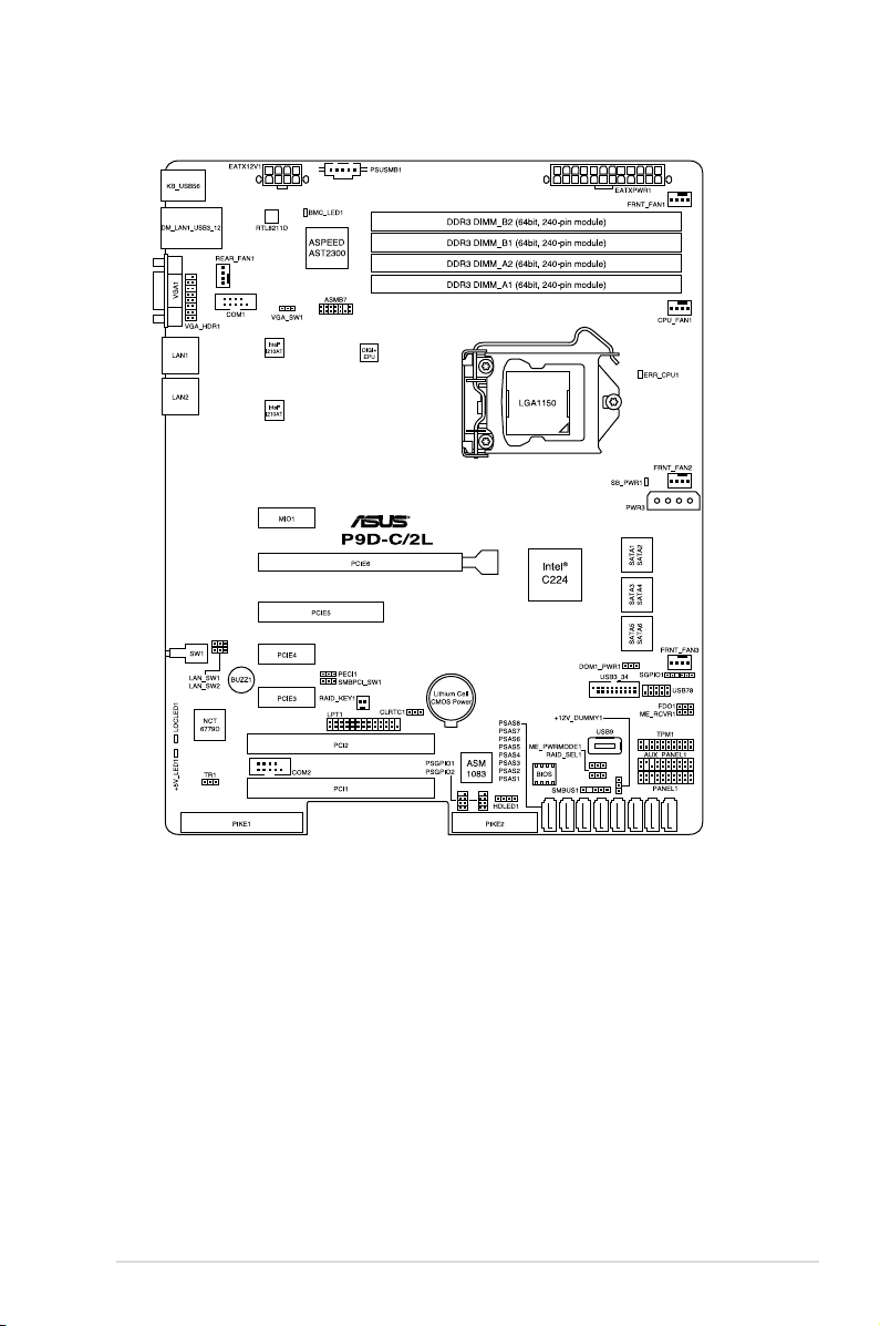
A.2 P9D-C/2L block diagram ........................................................................... A-4
vi
Notices
Federal Communications Commission Statement
This device complies with Part 15 of the FCC Rules. Operation is subject to the
following two conditions:
This device may not cause harmful interference, and
•
This device must accept any interference received including interference that
•
may cause undesired operation.
This equipment has been tested and found to comply with the limits for a Class B
digital device, pursuant to Part 15 of the FCC Rules. These limits are designed to
provide reasonable protection against harmful interference in a residential installation.
This equipment generates, uses and can radiate radio frequency energy and, if not
installed and used in accordance with manufacturer’s instructions, may cause harmful
interference to radio communications. However, there is no guarantee that interference
will not occur in a particular installation. If this equipment does cause harmful
interference to radio or television reception, which can be determined by turning the
equipment off and on, the user is encouraged to try to correct the interference by one
or more of the following measures:
Reorient or relocate the receiving antenna.
•
Increase the separation between the equipment and receiver.
•
Connect the equipment to an outlet on a circuit different from that to which the
•
receiver is connected.
Consult the dealer or an experienced radio/TV technician for help.
•
The use of shielded cables for connection of the monitor to the graphics card is required to
assure compliance with FCC regulations. Changes or modications to this unit not expressly
approved by the party responsible for compliance could void the user’s authority to operate
this equipment.
Canadian Department of Communications Statement
This digital apparatus does not exceed the Class B limits for radio noise emissions
from digital apparatus set out in the Radio Interference Regulations of the Canadian
Department of Communications.
This class B digital apparatus complies with Canadian ICES-003.
REACH
Complying with the REACH (Registration, Evaluation, Authorization, and Restriction of
Chemicals) regulatory framework, we publish the chemical substances in our products
at ASUS REACH website at http://csr.asus.com/english/REACH.htm.
vii

Safety information
Electrical safety
To prevent electrical shock hazard, disconnect the power cable from the electrical
•
outlet before relocating the system.
When adding or removing devices to or from the system, ensure that the power
•
cables for the devices are unplugged before the signal cables are connected.
If possible, disconnect all power cables from the existing system before you
add a device.
Before connecting or removing signal cables from the motherboard, ensure that
•
all power cables are unplugged.
Seek professional assistance before using an adapter or extension cord. These
•
devices could interrupt the grounding circuit.
Make sure that your power supply is set to the correct voltage in your area. If
•
you are not sure about the voltage of the electrical outlet you are using, contact
your local power company.
If the power supply is broken, do not try to x it by yourself. Contact a qualied
•
service technician or your retailer.
Operation safety
Before installing the motherboard and adding devices on it, carefully read all the
•
manuals that came with the package.
Before using the product, make sure all cables are correctly connected and the
•
power cables are not damaged. If you detect any damage, contact your dealer
immediately.
To avoid short circuits, keep paper clips, screws, and staples away from
•
connectors, slots, sockets and circuitry.
Avoid dust, humidity, and temperature extremes. Do not place the product in any
•
area where it may become wet.
Place the product on a stable surface.
•
If you encounter technical problems with the product, contact a qualied service
•
technician or your retailer.
viii
DO NOT throw the motherboard in municipal waste. This product has been designed to enable
proper reuse of parts and recycling. This symbol of the crossed out wheeled bin indicates that
the product (electrical and electronic equipment) should not be placed in municipal waste.
Check local regulations for disposal of electronic products.
DO NOT throw the mercury-containing button cell battery in municipal waste. This symbol of the
crossed out wheeled bin indicates that the battery should not be placed in municipal waste.
Australia statement notice
From 1 January 2012 updated warranties apply to all ASUS products, consistent with
the Australian Consumer Law. For the latest product warranty details please visit
http://support.asus.com. Our goods come with guarantees that cannot be excluded
under the Australian Consumer Law. You are entitled to a replacement or refund for a
major failure and compensation for any other reasonably foreseeable loss or damage.
You are also entitled to have the goods repaired or replaced if the goods fail to be of
acceptable quality and the failure does not amount to a major failure.
If you require assistance please call ASUS Customer Service 1300 2787 88 or visit
us at http://support.asus.com
ix

About this guide
This user guide contains the information you need when installing and conguring
the motherboard.
How this guide is organized
This user guide contains the following parts:
• Chapter 1: Product introduction
This chapter describes the features of the motherboard and the new technologies
it supports.
• Chapter 2: Hardware information
This chapter lists the hardware setup procedures that you have to perform when
installing system components. It includes description of the switches, jumpers,
and connectors on the motherboard.
• Chapter 3: Powering up
This chapter describes the power up sequence and ways of shutting down the
system.
• Chapter 4: BIOS setup
This chapter tells how to change system settings through the BIOS Setup menus.
Detailed descriptions of the BIOS parameters are also provided.
• Chapter 5: RAID conguration
This chapter provides instructions for setting up, creating, and conguring RAID
sets using the available utilities.
• Chapter 6: Driver installation
This chapter provides instructions for installing the necessary drivers for different
system components.
• Appendix: Reference information
This appendix includes additional information that you may refer to when
conguring the motherboard.
Where to nd more information
Refer to the following sources for additional information and for product and software
updates.
1. ASUS websites
The ASUS website provides updated information on ASUS hardware and
software products. Refer to the ASUS contact information.
2. Optional documentation
Your product package may include optional documentation, such as warranty
yers, that may have been added by your dealer. These documents are not
part of the standard package.
x

Conventions used in this guide
To ensure that you perform certain tasks properly, take note of the following symbols
used throughout this manual.
DANGER/WARNING: Information to prevent injury to yourself when trying to
complete a task.
CAUTION: Information to prevent damage to the components when trying to
complete a task
IMPORTANT: Instructions that you MUST follow to complete a task.
.
NOTE: Tips and additional information to help you complete a task.
Typography
Bold text
Italics
<Key> Keys enclosed in the less-than and greater-than sign means
<Key1> + <Key2> + <Key3> If you must press two or more keys simultaneously, the key
Command
Indicates a menu or an item to select.
Used to emphasize a word or a phrase.
that you must press the enclosed key.
Example: <Enter> means that you must press the Enter or
Return key.
names are linked with a plus sign (+).
Example: <Ctrl> + <Alt> + <Del>
Means that you must type the command exactly as
shown, then supply the required item or value enclosed
in brackets.
Example: At DOS prompt, type the command line:
format A:/S
xi
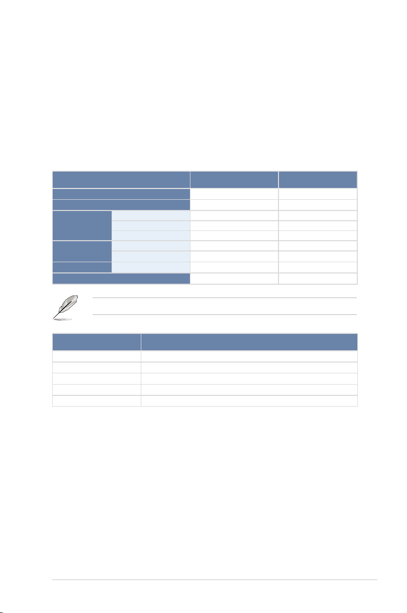
P9D-C Series Specications Summary
Model Name
Processor Support / System Bus
Core Logic
Form Factor
Fan Speed Control
Rack Ready
ASUS Features
Memory
Expansion
Slots (follow
SSI Location #)
Storage
Networking
(Rack and Pedestal
dual use)
ASWM Enterprise
Total Slots
Capacity
Memory Type
Total PCI/PCI-E Slots
Slot Location 1
Slot Location 2
Slot Location 3
Slot Location 4
Slot Location 5
Slot Location 6
Slot Location 7
Additional Slot 1
SATA Controller
LAN
P9D-C/4L P9D-C/2L
1 x Socket LGA1150
Intel® Xeon® Processor E3-1200 v3 product
Family
Intel® Core™ i3 Processor Family*
Intel® C224 Chipset
ATX, 12 in. x 9.6 in.
4 (2 Channels)
Maximum up to 32GB
DDR3 1333/1600 ECC UDIMM
6
1 x PCI 32bit/33 MHz
1 x PCI 32bit/33 MHz
1 x PCI-E x1 (x1 Gen2 link)
1 x PCI-E x1 (x1 Gen2 link)
1 x PCI-E x8 (x4 Gen3 link)
1 x PCI-E x16 (x8 Gen3 link)
MIO supported
1 x PIKE Slot for Storage expansion
(x4 Gen3 link)
Intel® C224:
- 2 x SATA 3Gb/s ports
- 4 x SATA 6Gb/s ports
- Intel® Rapid Storage Technology Enterprise
(RSTe) supports software RAID 0, 1, 10, & 5
(Windows®)
4 x Intel® I210AT 2 x Intel® I210AT
1 x Management LAN
* Refer to www.asus.com for the complete list of supported CPUs.
(continued on the next page)
xii
Model Name
Graphic
Onboard I/O
Connectors
Rear I/O
Connectors
Management
Solution
Monitoring
Environment
VGA
TPM Header
PSU Connector
SATA DOM Power
Connector
Management
Header
USB Connector/
Header
Fan Header
SMBus
Chassis Intruder
Front LAN LED
Serial Port Header
VGA Header
External USB Port
VGA Port
RJ-45
PS/2 KB/Mouse
Software
Out of Band
Remote
Management
CPU Temperature
FAN RPM
P9D-C/4L P9D-C/2L
Aspeed AST2300 + 32MB VRAM
1
24-pin ATX power connector
8-pin ATX 12V power connector
4-pin power connector
On-board header for optional management card
1 x USB 3.0 pin header (up to 2 devices)
1 x USB 2.0 pin header (up to 2 devices)
1 x USB 2.0 pin header (Type A USB socket)
5 x 4 pin headers
1
1
4 2
2
1
2 x USB 3.0
2 x USB 2.0
1
4 x GbE LAN
1 Management LAN
2 x GbE LAN
1 Management LAN
1
ASWM Enterprise
Optional ASMB7-iKVM for KVM-over-Internet
Operation temperature:
10oC – 35oC (50oF – 95oF)
Non operation temperature:
-40oC – 70oC (-40oF – 158oF)
Non operation humidity:
20% – 90% (Non condensing)
** Specications are subject to change without notice.
xiii

xiv

Chapter 1:
Product Introduction

Chapter summary
1
This chapter describes the motherboard features and the new technologies it
supports. This chapter contains the following sections:
1.1 Welcome! ....................................................................................................1-3
1.2 Package contents.......................................................................................1-3
1.3 Serial number label .................................................................................... 1-4
1.4 Special features..........................................................................................1-4
ASUS P9D-C Series
1.1 Welcome!
Thank you for buying an ASUS® P9D-C Series motherboard!
The motherboard delivers a host of new features and latest technologies, making it
another standout in the long line of ASUS quality motherboards!
Before you start installing the motherboard and hardware devices on it, check the
items in your package with the list below.
1.2 Package contents
Check your motherboard package for the following items.
Standard Gift Box Pack Standard Bulk Pack
I/O Shield
Plate for LGA1150
Cables
Application CD
Documentation
Packing Qty.
Optional items Description
PIKE 2008 LSI 8-port SAS 6G RAID card
PIKE 2108 LSI 8-port SAS 6G HW RAID card
PIKE 2208 LSI 8-port SAS 6G HW RAID card
PIKE 9230 MARVELL 4-port SATA 6G RAID card
ASMB7-iKVM Remote Management solution provides KVM over IP solution
SATA DOM Power cable
SATA 3G cable
SATA 6G cable
Support CD
ASWM Enterprise SDVD
Motherboard User Guide
If any of the above items is damaged or missing, contact your retailer.
1
1 -1 --
2 -4 -1 1
1 1
1 1
1 pc per carton 10 pcs per carton
1
ASUS P9D-C Series
1-3

1.3 Serial number label
Before requesting support from the ASUS Technical Support team, you must take
note of the motherboard's serial number containing 12 characters
shown as the gure below. With the correct serial number of the product, ASUS
Technical Support team members can then offer a quicker and satisfying solution
to your problems.
xxS2xxxxxxxx
P9D-C Series
xxS2xxxxxxxx
Made
in
China
合格
1.4 Special features
1.4.1 Product highlights
Latest processor technology
This motherboard supports the latest Intel® Xeon® E3-1200 v3/Core™ i3 processor
series in LGA1150 package, which has memory and PCI Express controller
integrated to support 2-channel (4 DIMMs) DDR3 memory and 16 PCI Express
3.0 lanes. The Intel® Xeon® E3-1200 V3 Core™ i3 processor is one of the most
powerful and energy efcient CPU in the world.
Intel® Turbo Boost
Intel® Turbo Boost opportunistically and automatically allows the processor to
run faster than the marked frequency if the processor is operating below power,
temperature and current limits. This technology increases performance of both
multi-threaded and single-threaded workloads.
Intel® Hyper Threading
The thread-level parallelism on each processor makes more efcient use of the
processor resources, higher processing throughout and improved performance on
today's multi-threaded software.
Intel® EM64T
The motherboard supports Intel® processors with the Intel® EM64T (Extended
Memory 64 Technology). The Intel® EM64T feature allows your computer to run on
64-bit operating systems and access larger amounts of system memory for faster
and more efcient computing.
PCI Express 3.0
PCI Express® 3.0 (PCIe 3.0) is the PCI Express bus standard that provides twice the
performance and speed of PCIe 2.0. It provides an optimal graphics performance,
unprecedented data speed, and seamless transition with its complete backward
compatibility to PCIe 1.0/2.0 devices.
1-4
Chapter 1: Product introduction

Intel® I210AT LAN Solution
The motherboard comes with quad Gigabit LAN controllers (dual controllers for
P9D-C/2L) and ports which provide a total solution for your networking needs. The
onboard Intel® I210AT Gigabit LAN controllers use the PCI Express interface and
could achieve network throughput close to Gigabit bandwidth.
Enhanced Intel SpeedStep Technology (EIST)
The Enhanced Intel SpeedStep Technology (EIST) intelligently manages the
CPU resources by automatically adjusting the CPU voltage and core frequency
depending on the CPU loading and system speed or power requirement.
Serial ATA II technology
The motherboard supports the Serial ATA II 3 Gb/s technology through the Serial
ATA interface and Intel® C224 chipset. The Serial ATA II specication provides
twice the bandwidth of the current Serial ATA products with a host of new
features, including Native Command Queuing (NCQ), Power Management (PM)
Implementation Algorithm, and Hot Swap. Serial ATA allows thinner, more exible
cables with lower pin count and reduced voltage requirements.
Serial ATA III technology
The motherboard supports the Serial ATA III 6 Gb/s technology through the Serial
ATA interface and Intel® C224 chipset. Get enhanced scalability, faster data
retrieval, double the bandwidth of current bus systems with up to 6Gbps data
transfer rates.
USB 2.0 technology
The motherboard implements the Universal Serial Bus (USB) 2.0 specication that
dramatically increases the connection speed from the 12 Mbps bandwidth on USB
1.1 to a fast 480 Mbps on USB 2.0. USB 2.0 is backward compatible with USB 1.1.
USB 3.0 technology
The motherboard implements the Universal Serial Bus 3.0 (USB 3.0) that has
a connection speed of up to 5 Gbps - ten times faster than USB 2.0. Backward
compatible with USB 2.0, it also supports fast-charging of supported devices.
Temperature, fan, and voltage monitoring
The CPU temperature is monitored to prevent overheating and damage. The
system fan rotations per minute (RPM) is monitored for timely failure detection.
The chip monitors the voltage levels to ensure stable supply of current for critical
components.
ASUS P9D-C Series
1-5

DDR3 memory support
The motherboard supports ECC UDIMM DDR3 memory that features data transfer
rates of 1600/1333 MHz to meet the higher bandwidth requirements of server
and workstation applications. The dual-channel DDR3 architecture boosts system
performance, eliminates bottlenecks with peak bandwidth up to 25Gb/s, and
dramatically reduces the memory voltage to just 1.5V compared to DDR2's memory
voltage of 1.8V.
1.4.2 Innovative ASUS features
ASUS Fan Speed technology
The ASUS Fan Speed technology smartly adjusts the fan speeds according to the
system loading to ensure quiet, cool, and efcient operation.
PIKE (Proprietary I/O Kit Expansion)
PIKE is an on-demand upgrade kit for users. This ASUS unique feature enables
users to choose their preferred I/O solutions. ASUS provides multiple SAS solutions
for different segments and purposes and PIKE saves lots of validation efforts and
hardware cost for end users. Moreover, the special patent design offers multiple I/O
solutions without occupying the Slot 6 in 1U system.
ASUS MIO Audio card
The ASUS MIO audio card is a discrete 8-channel high denition audio (High Denition
Audio previously codenamed Azalia) CODEC that enables the clearest high quality
audio output. It has jack-sensing feature, retasking functions, and multi-streaming
technology that simultaneously send different audio streams to different destinations
for high-end sound quality.
1-6
Chapter 1: Product introduction

Chapter 2:
Hardware Information

Chapter summary
2
This chapter lists the hardware setup procedures that you have to perform when
installing system components. It includes description of the jumpers and connectors
on the motherboard. This chapter contains the following sections:
2.1 Before you proceed ...................................................................................2-3
2.2 Motherboard overview ............................................................................... 2-4
2.3 Central Processing Unit (CPU) .................................................................2-9
2.4 System memory .......................................................................................2-15
2.5 Expansion slots........................................................................................2-17
2.6 Onboard LEDs .......................................................................................... 2-23
2.7 Jumpers ....................................................................................................2-26
2.8 Connectors ...............................................................................................2-29
ASUS P9D-C Series

2.1 Before you proceed
Take note of the following precautions before you install motherboard components or change
any motherboard settings.
• Unplug the power cord from the wall socket before touching any component.
• Use a grounded wrist strap or touch a safely grounded object or a metal object, such
as the power supply case, before handling components to avoid damaging them due
to static electricity.
• Hold components by the edges to avoid touching the ICs on them.
• Whenever you uninstall any component, place it on a grounded antistatic pad or in the
bag that came with the component.
• Before you install or remove any component, ensure that the power supply is switched
off or the power cord is detached from the power supply. Failure to do so may cause
severe damage to the motherboard, peripherals, and/or components.
ASUS P9D-C Series
2-3
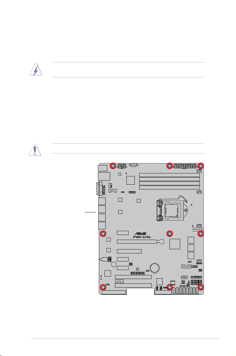
2.2 Motherboard overview
Before you install the motherboard, study the conguration of your chassis to ensure that the
motherboard ts into it.
To optimize the motherboard features, we highly recommend that you install it in an ATX 1.1
compliant chassis.
Ensure to unplug the chassis power cord before installing or removing the motherboard.
Failure to do so can cause you physical injury and damage motherboard components!
2.2.1 Placement direction
When installing the motherboard, ensure that you place it into the chassis in the correct
orientation. The edge with external ports goes to the rear part of the chassis as indicated in
the image below.
2.2.2 Screw holes
Place nine (9) screws into the holes indicated by circles to secure the motherboard to the
chassis.
DO NOT overtighten the screws! Doing so can damage the motherboard.
Place this side towards
2-4
the rear of the chassis
Chapter 2: Hardware information
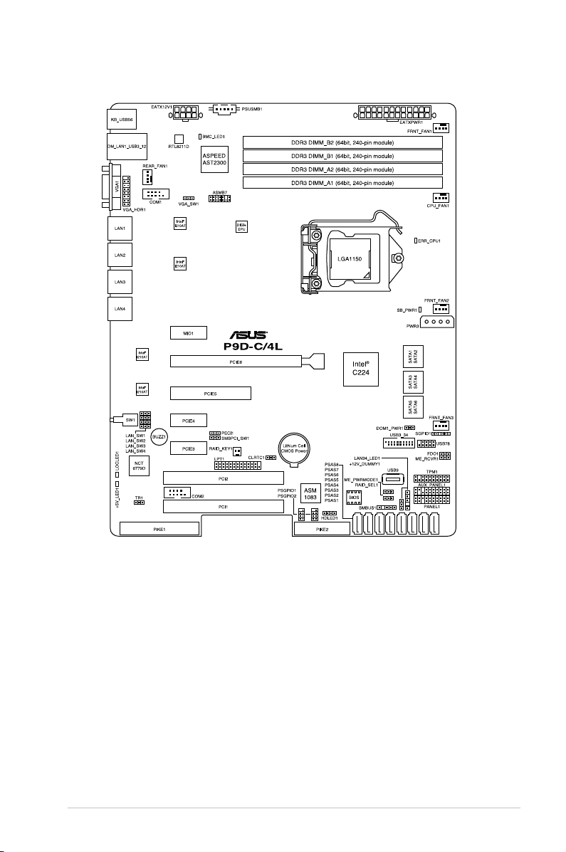
2.2.3 Motherboard layout
ASUS P9D-C Series
2-5
2-6
Chapter 2: Hardware information
2.2.4 Layout contents
Slots/Sockets Page
1. CPU sockets 2-9
2. DDR3 sockets 2-15
3. PCI Express x16 / PCI Express x8 / PCI Express x1 / PCI 2-18
4. PIKE slot 2-19
Onboard LEDs Page
1. Standby Power LED (SB_PWR1)Standby Power LED (SB_PWR1) 2-23
2. Baseboard Management Controller LED (BMC_LED1)Baseboard Management Controller LED (BMC_LED1) 2-23
3. CPU Warning LED (ERR_CPU1)CPU Warning LED (ERR_CPU1) 2-24
4. Power LED (+5V_LED1)Power LED (+5V_LED1) 2-24
5. Location LED (LOCLED1)Location LED (LOCLED1) 2-25
Jumpers
1. Clear RTC RAM (CLRTC1) 2-26
2. VGA controller setting (3-pin VGA_SW1) 2-27
3. LAN controller settingLAN controller setting
(3-pin LAN_SW1, LAN_SW2, LAN_SW3, LAN_SW4)
4. RAID conguration utility selection (3-pin RAID_SEL1) 2-28
5. Platform Environmental Control Interface (PECI) SettingPlatform Environmental Control Interface (PECI) Setting
(3-pin PECI1)
Rear panel connectors Page
1. PS/2 keyboard/mouse port (purple/green) 2-29
2. RJ-45 port for iKVM 2-29
3. Video Graphics Adapter portVideo Graphics Adapter port 2-29
4. RJ-45 ports for LAN.RJ-45 ports for LAN. 2-29
5. Power-on ButtonPower-on Button 2-29
6. Location LEDLocation LED 2-29
7. Power LEDPower LED 2-29
8. USB 2.0 ports 1 and 2USB 2.0 ports 1 and 2 2-29
9. USB 3.0 ports 1 and 2USB 3.0 ports 1 and 2 2-29
Page
2-27
2-28
ASUS P9D-C Series
2-7

Internal connectors
Page
1. Serial ATA 6.0/3.0 Gbps connectorSerial ATA 6.0/3.0 Gbps connector
(7-pin 6Gbps SATA1, SATA2, SATA3, SATA4 [Light Blue])6Gbps SATA1, SATA2, SATA3, SATA4 [Light Blue])1, SATA2, SATA3, SATA4 [Light Blue])SATA2, SATA3, SATA4 [Light Blue])2, SATA3, SATA4 [Light Blue])SATA3, SATA4 [Light Blue])3, SATA4 [Light Blue])SATA4 [Light Blue])4 [Light Blue])
2-30
(7-pin 3Gbps SATA5, SATA6 [Black])7-pin 3Gbps SATA5, SATA6 [Black])3Gbps SATA5, SATA6 [Black])SATA5, SATA6 [Black])5, SATA6 [Black])SATA6 [Black])6 [Black])
2. PSAS connectorsPSAS connectors
(7-pin PSAS1, PSAS2, PSAS3, PSAS4, PSAS5, PSAS6, PSAS7,
2-31
PSAS8 [Blue])
3. USB 2.0 connector (10-1 pin USB78; A-Type USB9)USB 2.0 connector (10-1 pin USB78; A-Type USB9) 2-32
4. USB 3.0 connector (20-1 pin USB3_34)USB 3.0 connector (20-1 pin USB3_34) 2-32
5. Thermal sensor cable connectors (3-pin TR1) 2-33
6. CPU, front, and rear fan connectorsCPU, front, and rear fan connectors
(4-pin CPU_FAN1, FRNT_FAN1, FRNT_FAN2, FRNT_FAN3,
2-33
REAR_FAN1)
7. Serial General Purpose Input/Output connector (6-1 pin
SGPIO1)
PIKE Serial General Purpose Input/Output connectorsPIKE Serial General Purpose Input/Output connectors
2-34
(8-1 pin PSGPIO1, PSGPIO2)
8. LAN34_LED connector (5-pin LAN34_LED1)LAN34_LED connector (5-pin LAN34_LED1) 2-35
9. Parallel port connector (26-1 pin LPT1)Parallel port connector (26-1 pin LPT1) 2-35
10. Serial port connectors (10-1 pin COM1/COM2) 2-36
11. Power Supply SMBus connector (5-pin PSUSMB1) 2-36
12. Trusted Platform Module connector (20-1 pin TPM1)Trusted Platform Module connector (20-1 pin TPM1) 2-37
13. SATA DOM power connector (4-pin PWR3)SATA DOM power connector (4-pin PWR3) 2-37
14. ATX power connectors (24-pin EATXPWR1, 8-pin EATX12V1)ATX power connectors (24-pin EATXPWR1, 8-pin EATX12V1) 2-38
15. System panel connector (20-1 pin PANEL1) 2-39
16. Auxiliary panel connector (20-2 pin AUX_PANEL1) 2-40
17. VGA connector (16-pin VGA_HDR1)VGA connector (16-pin VGA_HDR1) 2-41
18. Hard disk activity LED connector (4-pin HDLED1) 2-41
2-8
Chapter 2: Hardware information
2.3 Central Processing Unit (CPU)
The motherboard comes with a surface mount LGA1150 socket designed for the
Intel® Xeon® E3-1200 v3/Core™ i3 processor.
• Upon purchase of the motherboard, ensure that the PnP cap is on the socket and
the socket contacts are not bent. Contact your retailer immediately if the PnP cap
is missing, or if you see any damage to the PnP cap/socket contacts/motherboard
components. ASUS will shoulder the cost of repair only if the damage is shipment/
transit-related.
• Keep the cap after installing the motherboard. ASUS will process Return Merchandise
Authorization (RMA) requests only if the motherboard comes with the cap on the
LGA1150 socket.
• The product warranty does not cover damage to the socket contacts resulting from
incorrect CPU installation/removal, or misplacement/loss/incorrect removal of the PnP
cap.
2.3.1 Installing the CPU
To install the CPU:
1. Locate the CPU socket on the motherboard.
Before installing the CPU, ensure that the socket box is facing toward you and the load
lever is on your right.
ASUS P9D-C Series
2-9
2. Press the load lever with your thumb
(A), then move it to the right (B) until it is
released from the retention tab.
Do not remove the PnP cap yet from
the CPU socket. Doing so may bend
the pins of the socket.
3. Lift the load lever until the load plate is
completely lifted.
4. Position the CPU above the socket,
ensuring that the gold triangle mark is
on the bottom-left corner of the socket,
then t the CPU notches to the socket's
alignment keys.
Load lever
Retention tab
Load plate
CPU notches
2-10
The CPU ts in only one orientation.
DO NOT force the CPU into the
socket to prevent bending the pins on
the socket and damaging the CPU.
Gold
triangle
mark
Alignment
Alignment
key
key
Chapter 2: Hardware information
 Loading...