


P4V800-X
Motherboard
T1432
© 2003
2
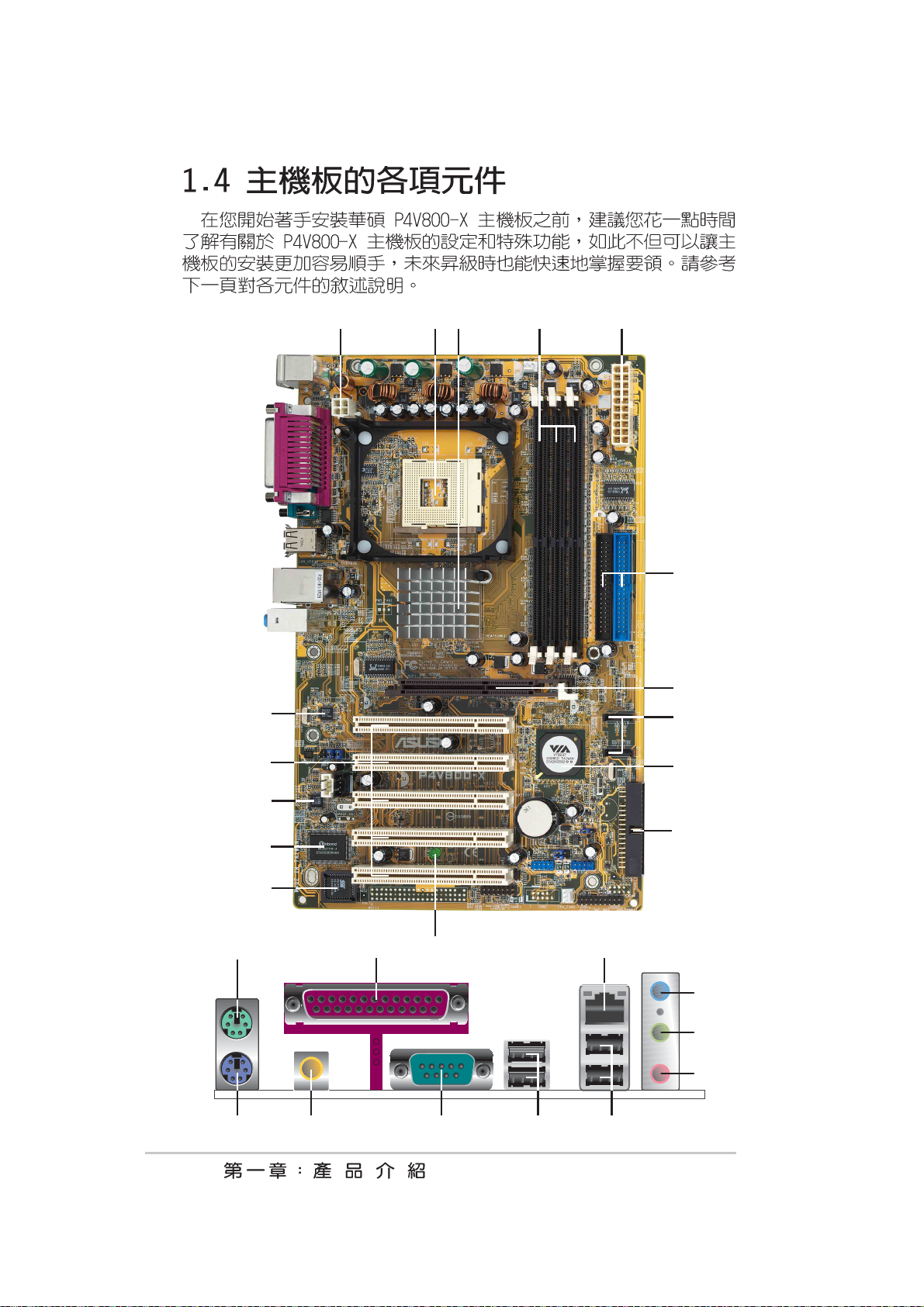
345
•
•
•
•
•
•
•
•
•
•
•
•
•
•
•
6
TM
e
12
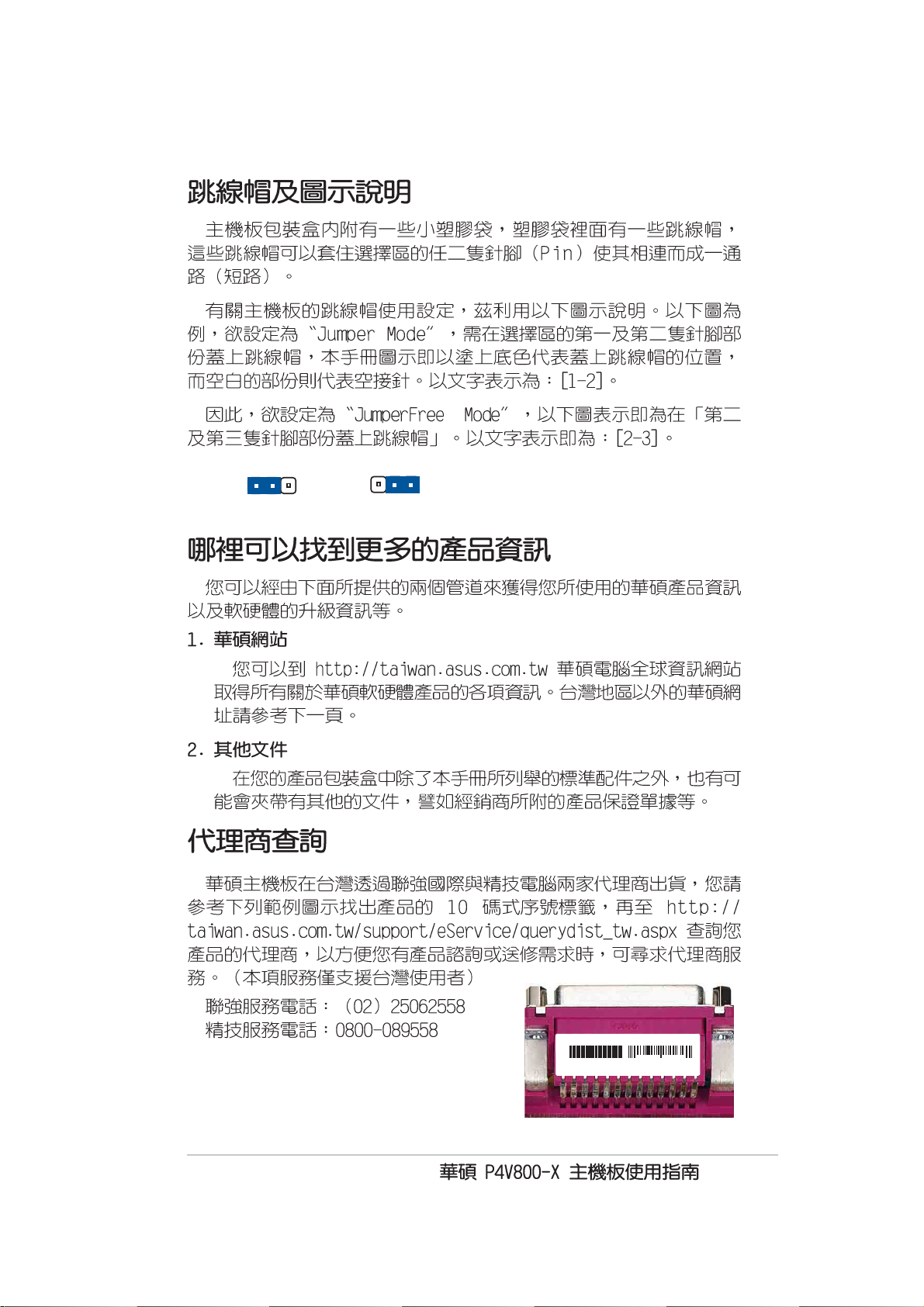
Jumper Mode
23
Jumper Fre
(Default)
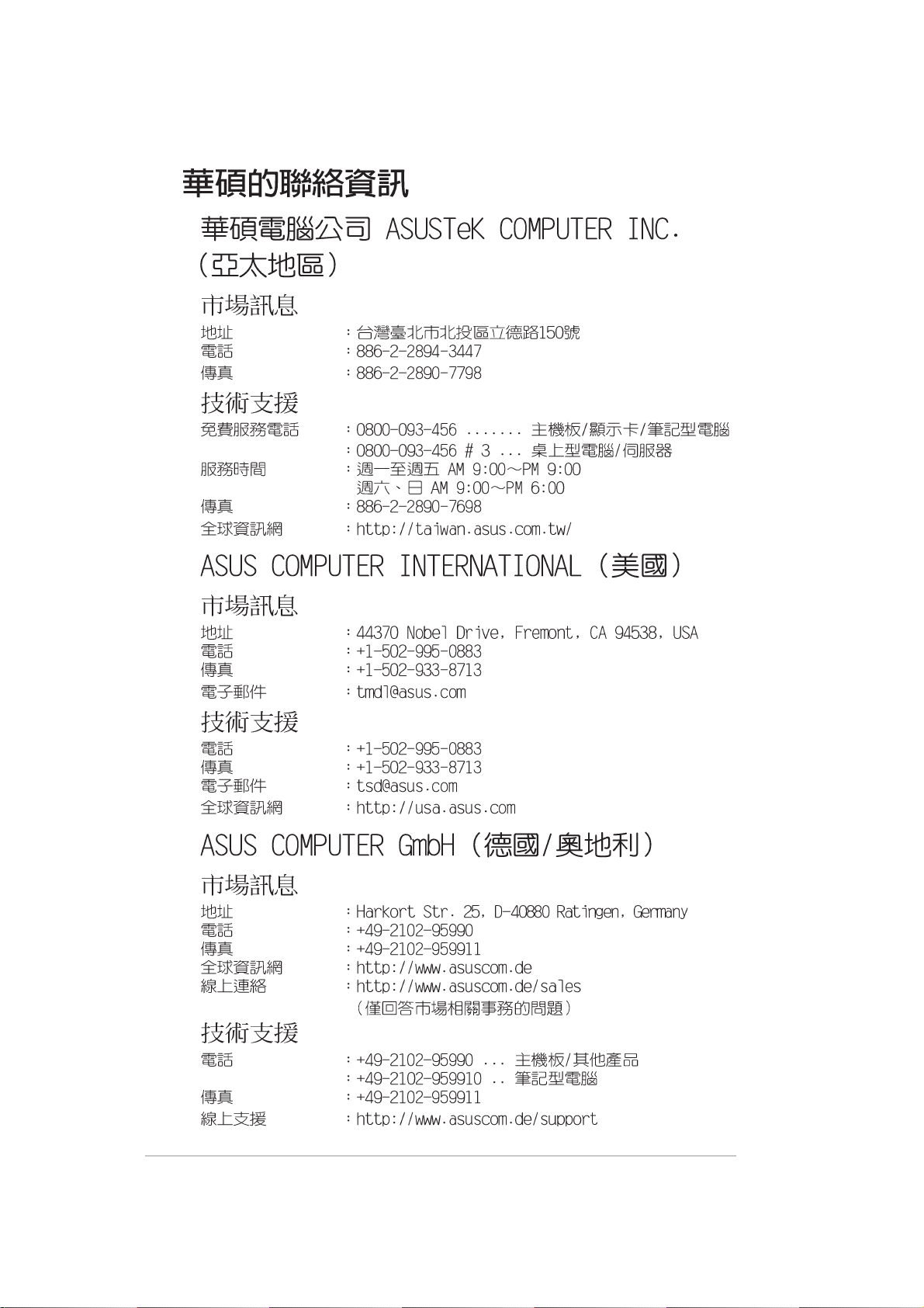
P4V800-X-TAYZ
10839 1103660
11XX11XX11
7
8
® ®
®
9
10
1-1
1-2
1-3
17
0
1
2
18 19
432 5
6
1
0
7
16
15
8
9
14
1
13
12
11
2
2
2
27 24
2526
23
1-4
1-5
1-6
1-7
®
19.3cm 7.6in)
ATX12V1
USBPW12
USBPW34
CPU_FAN1
Socket 478
30.5cm (12.0in)
SATA1
1-8
FP_AUDIO
CD
AUX
P4V800-X
SB_PWR1
GAME1
USB78
CHA_FAN1
CHASSIS1
USBPW78
USBPW56
USB56
SATA2
FLOPPY
CLRTC1
PANEL1
P4V800-X
d
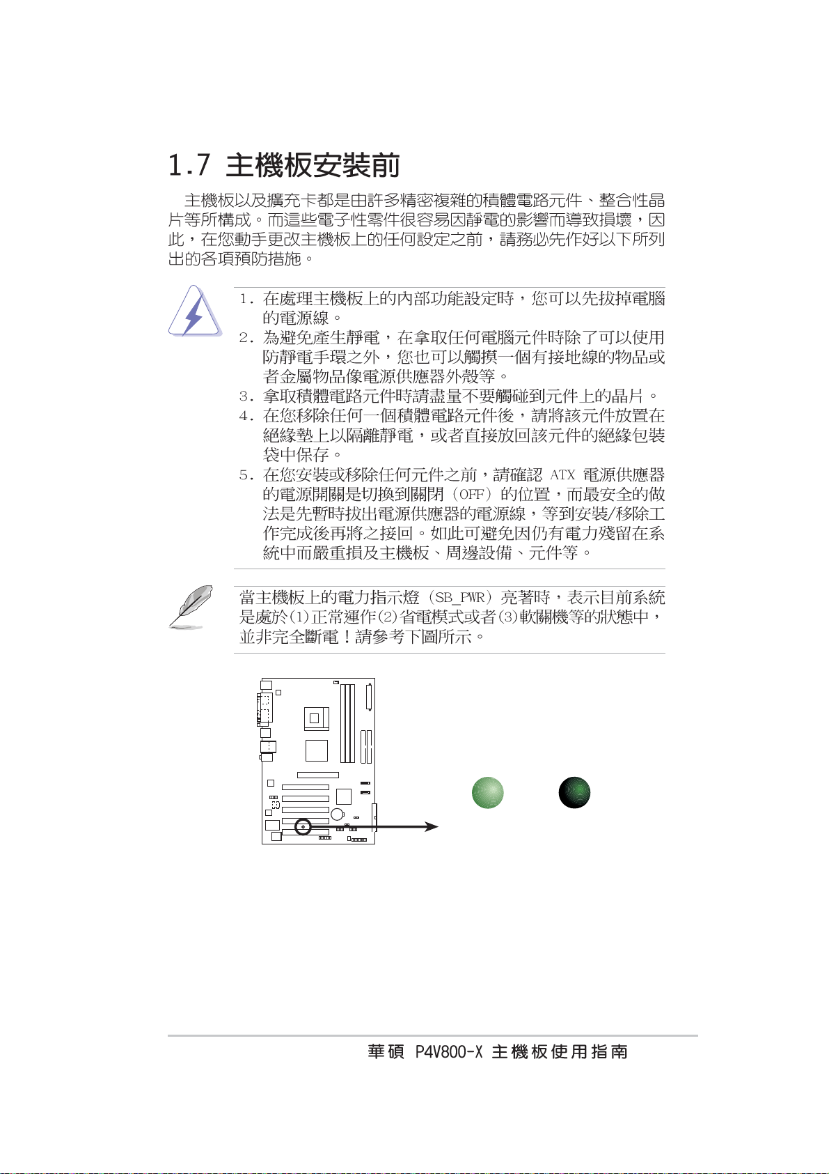
P4V800-X Onboard LED
ON
Standby
Power
SB_PWR1
OFF
Powere
Off
1-9
®
®
®
1-10
®
®
®
®
®
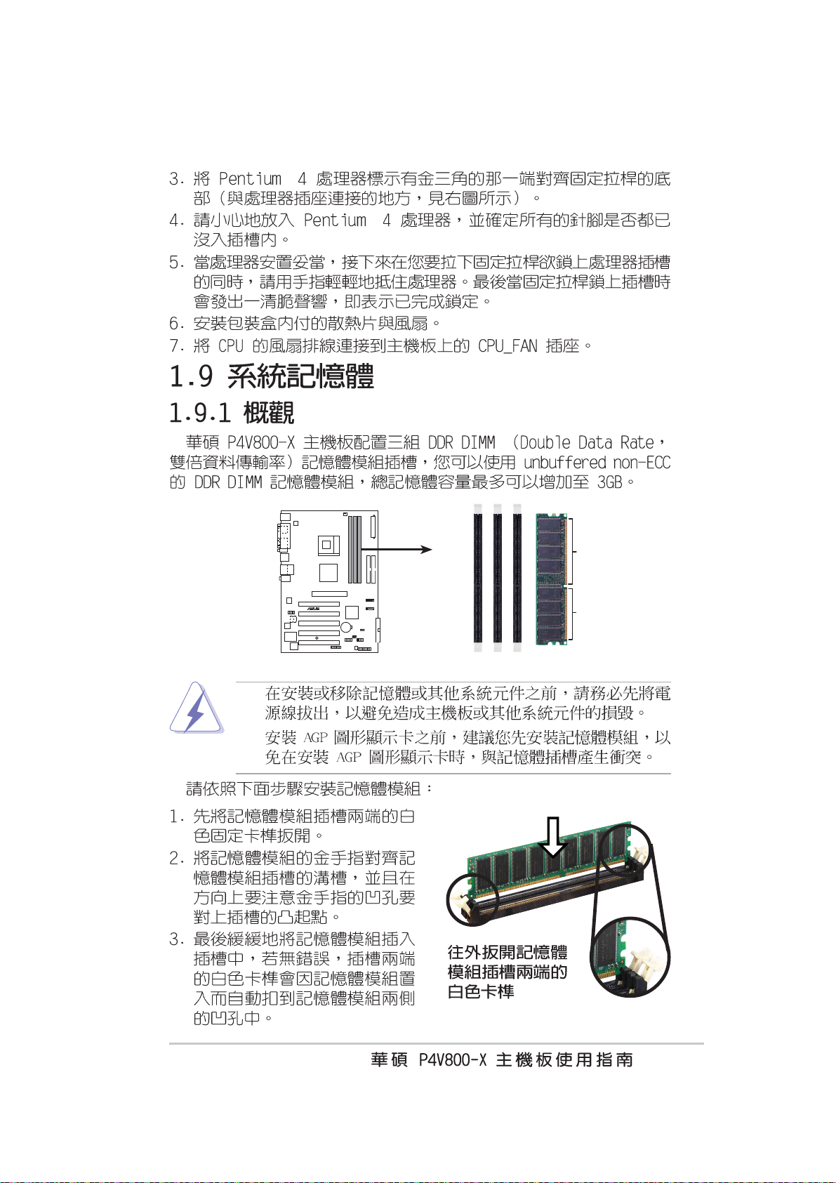
DIMM1
DIMM2
DIMM3
P4V800-X
P4V800-X 184-Pin DDR DIMM Sockets
•
•
80 Pins 104 Pins
1-11
1-12

ABCD
1-13

P4V800-X
®
P4V800-X Accelerated Graphics Port (AGP)
Keyed for 1.5v
1-14

®
3
3
B
B
USBPW12
USBPW34
21
2
P4V800-X
P4V800-X USB Device Wake Up
+5V
(Default)
USBPW78
USBPW56
21
+5V
(Default)
+5VS
2
+5VS
1-15

P4V800-X
P4V800-X Clear RTC RAM
CLRTC1
12 23
Normal Clear CMOS
(Default)
1-16

1
1
®
1
PIN 1
P4V800-X
P4V800-X Floppy Disk Drive Connector
FLOPPY
CPU_FAN
GND
Rotation
+12V
P4V800-X
CHA_FAN
Rotation
+12V
GND
P4V800-X 12-Volt Fan Connectors
1-17

P4V800-X
1-18
P4V800-X IDE Connectors
SEC_IDE1
PRI_IDE1
PIN 1

®
+12.0VDC
PWR_OK
+5.0VDC
P4V800-X
+5.0VDC
+3.3VDC
+3.3VDC
P4V800-X ATX Power Connectors
P4V800-X
ATXPWR1 ATX12V1
Pin 1
+5VSB
COM
COM
COM
+5.0VDC
+5.0VDC
-5.0VDC
COM
COM
COM
PS_ON#
COM
-12.0VDC
+3.3VDC
GND
+12V DC
+5VA
AGND
FP_AUDIO1
MIC2
MICPWR
BLINE_OUT_L
BLINE_OUT_R
NC
Line out_L
Line out_R
GND
+12V DC
P4V800-X Front Panel Audio Connector
1-19

el
P4V800-X
®
P4V800-X USB 2.0 Header
P4V800-X
USB78
1
USB+5V
USB_P8-
USB_P8+
USB+5V
USB_P7-
USB_P7+
GND
GND
NC
CD1(Black)AUX1(White)
USB56
Right Audio Chann
Ground
Ground
Left Audio Channel
1
USB+5V
USB_P6-
USB_P6+
USB+5V
USB_P5-
USB_P5+
GND
GND
NC
P4V800-X Internal Audio Connectors
1-20

P4V800-X
®
®
1
t)
P4V800-X Game Connector
GAME1
CHASSIS
+5V
J1B2
MIDI_IN
GND
J1CY
J2B2
J2CY
GND
J1CX
J1B1
+5V
+5V
J2B1
J2CX
MIDI_OUT
+5VSB_MB
Chassis Signal
P4V800-X
GND
(Defaul
P4V800-X Chassis Alarm Lead
1-21

.
Power LED
Speaker
Connector
PWR
Ground
ExtSMI#
ATX Power
Switch*
Ground
Speaker
Ground
+5V
Reset
Ground
Ground
Reset SW
P4V800-X
PLED-
PLED+
IDE_LED-
IDE_LED+
IDE_LED
SMI Lead
* Requires an ATX power supply
P4V800-X System Panel Connector
•
•
•
1-22
•
•
•

2-1

A:\>afudos /iP4V800-X.rom
AMI Firmware Update Utility - Version 1.10
Copyright (C) 2002 American Megatrends, Inc. All rights reserved.
Reading file ..... done
Erasing flash .... done
Writing flash .... 0x0008CC00 (9%)
A:\>afudos /iP4V800-X.rom
AMI Firmware Update Utility - Version 1.10
Copyright (C) 2002 American Megatrends, Inc. All rights reserved.
Reading file ..... done
Erasing flash .... done
Writing flash .... 0x0008CC00 (9%)
Verifying flash .. done
2-2
A:\>

User recovery requested. Starting BIOS recovery...
Checking for floppy...
User recovery requested. Starting BIOS recovery...
Checking for floppy...
Floppy found!
Reading file “P4V800-X.rom”. Completed.
Start flashing...
Flashed successfully. Rebooting.
2-3

Bad BIOS checksum. Starting BIOS recovery...
Checking for floppy...
Bad BIOS checksum. Starting BIOS recovery...
Checking for floppy...
Floppy found!
Reading file “P4V800-X.rom”. Completed.
Start flashing...
2-4

Bad BIOS checksum. Starting BIOS recovery...
Checking for floppy...
Bad BIOS checksum. Starting BIOS recovery...
Checking for floppy...
Floppy not found!
Checking for CD-ROM...
CD-ROM found.
Reading file “P4V800-X.rom”. Completed.
Start flashing...
2-5

2-6

System Time [11:10:19]
System Date [Thu 05/27/2003]
Legacy Diskette A [1.44M, 3.5 in]
Primary IDE Master :[ST320413A]
Primary IDE Slave :[ASUS CD-S340]
Secondary IDE Master :[Not Detected]
Secondary IDE Slave :[Not Detected]
System Information
Use [ENTER], [TAB]
or [SHIFT-TAB] to
select a field.
Use [+] or [-] to
configure system time.
Select Screen
Select Item
+- Change Field
Tab Select Field
F1 General Help
F10 Save and Exit
ESC Exit
2-7

System Time [18:29:27]
System Date [Wed 03/19/2003]
Legacy Diskette A [1.44M, 3.5 in]
Language [English]
Primary IDE Master :[ST320413A]
Primary IDE Slave :[ASUS CD-S520]
Secondary IDE Master :[Not Detected]
Secondary IDE Slave :[Not Detected]
Third IDE Master :[Not Detected]
Fourth IDE Master :[Not Detected]
IDE Configuration
System Information
Advanced Chipset settings
WARNING: Setting wrong values in the sections below
may cause system to malfunction.
Configure DRAM TIming by SPD [Disabled]
DRAM CAS# Latency [2.5 Clocks]
DRAM RAS# Precharge [4 Clocks]
DRAM RAS# to CAS# Delay [4 Clocks]
DRAM Precharge Delay [8 Clocks]
DRAM Burst Length [8 Clocks]
Graphic Adapter Priority [AGP/PCI]
Graphics Aperture Size [ 64 MB]
Spread Spectrum [Enabled]
ICH Delayed Transaction [Enabled]
MPS Revision [1.4]
Use [ENTER], [TAB]
or [SHIFT-TAB] to
select a field.
Use [+] or [-] to
configure system time.
Select Screen
Select Item
+- Change Field
Tab Select Field
F1 General Help
F10 Save and Exit
ESC Exit
Select Screen
Select Item
+- Change Option
F1 General Help
F10 Save and Exit
ESC Exit
2-8

System Time [11:10:19]
System Date [Thu 05/27/2003]
Legacy Diskette A [1.44M, 3.5 in]
Primary IDE Master :[ST320413A]
Primary IDE Slave :[ASUS CD-S340]
Secondary IDE Master :[Not Detected]
Secondary IDE Slave :[Not Detected]
System Information
Use [ENTER], [TAB]
or [SHIFT-TAB] to
select a field.
Use [+] or [-] to
configure system time.
Select Screen
Select Item
+- Change Field
Tab Select Field
F1 General Help
F10 Save and Exit
ESC Exit
2-9

Primary IDE Master
Device : Hard Disk
Vendor : ST320413A
Size : 20.0GB
LBA Mode : Supported
Block Mode : 16 Sectors
PIO Mode : 4
Async DMA : MultiWord DMA-2
Ultra DMA : Ultra DMA-5
SMART Monitoring: Supported
Type
LBA/Large Mode
Block (Multi-sector Transfer)
PIO Mode
DMA Mode
Smart Monitoring
32Bit Data Transfer
[Auto]
[Auto]
[Auto]
[Auto]
[Auto]
[Auto]
[Disabled]
Select the type
of device connected
to the system.
Select Screen
Select Item
+- Change Option
F1 General Help
F10 Save and Exit
ESC Exit
2-10

AMI BIOS
Version : 08.00.09
Build Date : 07/07/03
Processor
Type : Intel(R) Pentium(R) 4 CPU 1500MHz
Speed : 1500 MHz
Count : 1
System Memory
Size : 256MB
Select Screen
Select Item
+- Change Option
F1 General Help
F10 Save and Exit
ESC Exit
2-11

JumperFree Configuration
USB Configuration
CPU Configuration
Chipset
Onboard Devices Configuration
PCI PnP
Configure System Frequency/Voltage
AI Overclock Tuner [Standard]
CPU Reference Voltage [Auto]
DDR Reference Voltage [Auto]
Configure CPU.
Select Screen
Select Item
Enter Go to Sub-screen
F1 General Help
F10 Save and Exit
ESC Exit
2-12
Select Screen
Select Item
+- Change Option
F1 General Help
F10 Save and Exit
ESC Exit

Configure System Frequency/Voltage
AI Overclock Tuner [Manual]
CPU Frequency [133]
CPU Reference Voltage [Auto]
DDR Reference Voltage [Auto]
Select Screen
Select Item
+- Change Option
F1 General Help
F10 Save and Exit
ESC Exit
2-13

USB Configuration
Module Version : 2.22.4-5.3
USB Devices Enabled : None
USB 1.1 Ports Configuration [8 USB Ports]
USB 2.0 Ports Enable [Enabled]
Legacy USB Support [Auto]
USB 2.0 Controller Mode [HiSpeed]
USB Mass Storage Device Configuration
Enables USB host
controllers.
Select Screen
Select Item
+- Change Option
F1 General Help
F10 Save and Exit
ESC Exit
2-14

USB Mass Storage Device Configuration
USB Mass Storage Reset Delay [20 Sec]
No USB Mass Storage device detected
Device #1 N/A
Emulation Type [N/A]
Device #2 N/A
Emulation Type [N/A]
Device #3 N/A
Emulation Type [N/A]
Device #4 N/A
Emulation Type [N/A]
Device #5 N/A
Emulation Type [N/A]
Device #6 N/A
Emulation Type [N/A]
Number of seconds
POST waits for the USB
mass storage device
after that start unit
command.
Select Screen
Select Item
+- Change Option
F1 General Help
F10 Save and Exit
ESC Exit
2-15

Configure advanced CPU settings
Manufacturer : Intel(R)
Brand String : Intel(R) Pentium(R) 4 CPU 1500MHz
Frequency : 1500MHz
Ratio Status : Locked
Ratio Actual Value : 18
NorthBridge VIA P4X400/PT800 Configuration
SouthBridge VIA VT8237 Configuration
Select Screen
Select Item
+- Change Option
F1 General Help
F10 Save and Exit
ESC Exit
2-16
Select Screen
Select Item
+- Change Option
F1 General Help
F10 Save and Exit
ESC Exit

******** DRAM Timing ********
Configure SDRAM Timing by SPD [Enabled]
SDRAM Frequency [Auto]
SDRAM Burst Length [4QW]
SDRAM Command Rate [2T]
Primary Graphics Adapter [AGP]
V-Link 8X Supported [Enabled]
AGP Mode Auto
Graphics Aperture Size [64MB]
Select Screen
Select Item
+- Change Option
F1 General Help
F10 Save and Exit
ESC Exit
2-17

2-18

MPS Revision [1.1]
PCI Delay Transaction [Disabled]
OnBoard LAN [Enabled]
OnBoard LAN Boot ROM [Disabled]
OnBoard AC’97 Audio [Enabled]
Select Screen
Select Item
+- Change Option
F1 General Help
F10 Save and Exit
ESC Exit
2-19

Serial Port1 Address [3F8/IRQ4]
Parallel Port Address [378]
Parallel Port Mode [ECP]
ECP Mode DMA Channel [DMA3]
Parallel Port IRQ [IRQ7]
Onboard Game/MIDI Port [Disabled]
Select Screen
Select Item
+- Change Option
F1 General Help
F10 Save and Exit
ESC Exit
2-20

Advanced PCI/PnP settings
WARNING: Setting wrong values in the sections below
may cause system to malfunction.
Plug and Play OS [No]
PCI Latency Timer [64]
Allocate IRQ to PCI VGA [Yes]
Palette Snooping [Disabled]
PCI IDE BusMaster [Enabled]
IRQ3 [Available]
IRQ4 [Available]
IRQ5 [Available]
IRQ7 [Available]
IRQ9 [Available]
IRQ10 [Available]
IRQ11 [Available]
IRQ14 [Available]
IRQ15 [Available]
NO: Lets the bIOS
configure all the
devices in the system.
YES: Lets the
operating system
configure Plug and
Play (PnP) devices not
required for boot if
your system has a Plug
and Play operating
system.
Select Screen
Select Item
+- Change Option
F1 General Help
F10 Save and Exit
ESC Exit
2-21

2-22

Suspend Mode [S1 (POS) only]
Repost Video on S3 Resume [No]
ACPI 2.0 Support [No]
ACPI APIC Support [Enabled]
APM Configuration
Hardware Monitor
Configure CPU.
Select Screen
Select Item
Enter Go to Sub-screen
F1 General Help
F10 Save and Exit
ESC Exit
2-23

Power Management/APM [Enabled]
Video Power Down Mode [Suspend]
Hard Disk Power Down Mode [Suspend]
Suspend Time Out [Disabled]
Power Button Mode [On/Off]
Restore on AC Power Loss [Last State]
Wake Up/Power On by Ring [Disabled]
Power On by Onboard LAN [Disabled]
Power On by PCI Device [Disabled]
Power On by RTC Alarm [Disabled]
Power On by PS/2 Mouse [Disabled]
Power On by Keyboard [Disabled]
Enabled or disable
APM.
Select Screen
Select Item
+- Change Option
F1 General Help
F10 Save and Exit
ESC Exit
2-24

2-25

Hardware Monitor
CPU Temperature [21°C/69.5°F]
MB Temperature [37°C/98.5°F]
CPU Fan Speed [3479RPM]
Chassis Fan Speed [N/A]
CPU Reference Voltage [1.792V]
3.3V Voltage [3.392V]
5V Voltage [5.134V]
12V Voltage [11.840V]
CPU temperature
Select Screen
Select Item
+- Change Option
F1 General Help
F10 Save and Exit
ESC Exit
2-26

Boot Settings
Boot Device Priority
Boot Settings Configuration
Security
Specifies the Boot
Device Priority
sequence.
Select Screen
Select Item
Enter Go to Sub-screen
F1 General Help
F10 Save and Exit
ESC Exit
Boot Device Priority
1st Boot Device [First Floppy Drive]
2nd Boot Device [PM-ST320413A]
Specifies the boot
sequence from the
available devices.
A device enclosed in
parenthesis has been
disabled in the
corresponding type
menu.
Select Screen
Select Item
+- Change Option
F1 General Help
F10 Save and Exit
ESC Exit
2-27

Boot Settings Configuration
Quick Boot [Enabled]
Full Screen Logo [Enabled]
Add On ROM Display Mode [Force BIOS]
Bootup Num-Lock [On]
PS/2 Mouse Support [Auto]
Wait for ‘F1’ If Error [Enabled]
Hit ‘DEL’ Message Display [Enabled]\
Interrupt 19 Capture [Disabled]
Allows BIOS to skip
certain tests while
booting. This will
decrease the time
needed to boot the
system.
Select Screen
Select Item
+- Change Option
F1 General Help
F10 Save and Exit
ESC Exit
2-28

Security Settings
Supervisor Password Installed
User Password Not Installed
Change Supervisor Password
User Access Level [Full Access]
Change User Password
Clear User Password
Password Check [Setup]
Boot Sector Virus Protection [Disabled]
<Enter> to change
password.
<Enter> again to
disable password.
Select Screen
Select Item
+- Change Option
F1 General Help
F10 Save and Exit
ESC Exit
2-29

2-30

Exit Options
Exit & Save Changes
Exit & Discard Changes
Discard Changes
Load Setup Defaults
Exit system setup
after saving the
changes.
F10 key can be used
for this operation.
Select Screen
Select Item
Enter Go to Sub-screen
F1 General Help
F10 Save and Exit
ESC Exit
2-31

2-32

3-1

3-2

3-3

•
•
3-4

VIA Tech. RAID BIOS Ver 1.XX
Create Array
Delete Array
Create/Delete Spare
Select Boot Array
Serial Number View
Channel Drive Name Array Name Mode Size(GB) Status
Serial_Ch0 Master XXXXXXXXXX xxxxx xxx.xx Hdd
Serial_Ch1 Master XXXXXXXXXX xxxxx xxx.xx Hdd
Create a RAID array with
the hard disk attached to
VIA IDE controller
F1 : View Array/Disk Status
, : Move to next item
Enter: Confirme the selection
ESC : Exit
VIA Tech. RAID BIOS Ver 1.xx
Auto Setup For Data Security
Array Mode RAID 1 (Mirroring)
Select Disk Drives
Start Create Process
Channel Drive Name Array Name Mode Size(GB) Status
Serial_Ch0 Master XXXXXXXXXX xxxxx xxx.xx Hdd
Serial_Ch1 Master XXXXXXXXXX xxxxx xxx.xx Hdd
Create a RAID array with
the hard disk attached to
VIA IDE controller
F1 : View Array/Disk Status
, : Move to next item
Enter: Confirm the selection
ESC : Exit
3-5

4K
8K
16K
32K
64K
RAID 0 for performance
RAID 1 for data protection
3-6
The data on the selected disks will
be destroyed. Continue? Press Y/N
RAID 0 for performance
RAID 1 for data protection

Create only
Create and duplicate
The data on the selected disks will
be destroyed. Continue? Press Y/N
The selected drives will be destroyed.
Are you sure? Continue? Press Y/N
3-7

ESC : Exit
Channel Drive Name Array Name Mode Size(GB) Status
[ ]
Serial_Ch0 Master XXXXXXXXXX xxxxx xxx.xx Hdd
[ ]
Serial_Ch1 Master XXXXXXXXXX xxxxx xxx.xx Hdd
VIA Tech. RAID BIOS Ver 1.xx
Create Array
Delete Array
Create/Delete Spare
Select Boot Array
Serial Number View
Channel Drive Name Array Name Mode Size(GB) Status
Serial_Ch0 Master XXXXXXXXXX xxxxx xxx.xx Hdd
Serial_Ch1 Master XXXXXXXXXX xxxxx xxx.xx Hdd
Serial Number: xxxxxxxx
Create a RAID array with
the hard disk attached to
VIA IDE controller
F1 : View Array/Disk Status
, : Move to next item
Enter: Confirme the selection
ESC : Exit
3-8
 Loading...