


ASUS P3C2000 User Manual

R
P3C2000
JumperFree™ Camino Motherboard
USER’S MANUAL

USER'S NOTICE
No part of this manual, including the products and software described in it, may be reproduced, transmitted, transcribed, stored in a retrieval system, or translated into any language in
any form or by any means, except documentation kept by the purchaser for backup purposes,
without the express written permission of ASUSTeK COMPUTER INC. (“ASUS”).
ASUS PROVIDES THIS MANUAL “AS IS” WITHOUT WARRANTY OF ANY KIND,
EITHER EXPRESS OR IMPLIED, INCLUDING BUT NOT LIMITED T O THE IMPLIED
WARRANTIES OR CONDITIONS OF MERCHANT ABILITY OR FITNESS FOR A PARTICULAR PURPOSE. IN NO EVENT SHALL ASUS, ITS DIRECTORS, OFFICERS,
EMPLOYEES OR AGENTS BE LIABLE FOR ANY INDIRECT, SPECIAL, INCIDENTAL, OR CONSEQUENTIAL DAMAGES (INCLUDING DAMAGES FOR LOSS OF
PROFITS, LOSS OF BUSINESS, LOSS OF USE OR DATA, INTERRUPTION OF BUSINESS AND THE LIKE), EVEN IF ASUS HAS BEEN ADVISED OF THE POSSIBILITY
OF SUCH DAMAGES ARISING FROM ANY DEFECT OR ERROR IN THIS MANUAL
OR PRODUCT.
Product warranty or service will not be extended if: (1) the product is repaired, modified or
altered, unless such repair, modification of alteration is authorized in writing by ASUS; or (2)
the serial number of the product is defaced or missing.
Products and corporate names appearing in this manual may or may not be registered trademarks or copyrights of their respective companies, and are used only for identification or
explanation and to the owners’ benefit, without intent to infringe.
• Adobe and Acrobat are registered trademarks of Adobe Systems Incorporated.
• Intel, LANDesk, and Pentium are registered trademarks of Intel Corporation.
• Trend and ChipAwayVirus are trademarks of Trend Micro, Inc.
• Windows and MS-DOS are registered trademarks of Microsoft Corporation.
• ADI and SoundMAX are trademarks of Analog Devices, Inc..
The product name and revision number are both printed on the product itself. Manual revi-
sions are released for each product design represented by the digit before and after the period
of the manual revision number. Manual updates are represented by the third digit in the manual
revision number.
For previous or updated manuals, BIOS, drivers, or product release information, contact ASUS
at http://www.asus.com.tw or through any of the means indicated on the following page.
SPECIFICATIONS AND INFORMATION CONTAINED IN THIS MANUAL ARE FURNISHED FOR INFORMATIONAL USE ONLY, AND ARE SUBJECT TO CHANGE AT
ANY TIME WITHOUT NOTICE, AND SHOULD NOT BE CONSTRUED AS A COMMITMENT BY ASUS. ASUS ASSUMES NO RESPONSIBILITY OR LIABILITY FOR
ANY ERRORS OR INACCURACIES THAT MA Y APPEAR IN THIS MANUAL, INCLUDING THE PRODUCTS AND SOFTWARE DESCRIBED IN IT.
Copyright © 1999 ASUSTeK COMPUTER INC. All Rights Reserved.
Product Name: ASUS P3C2000
Manual Revision: 1.03 E499
Release Date: December 1999
2 ASUS P3C2000 User’s Manual

ASUS CONTACT INFORMATION
ASUSTeK COMPUTER INC. (Asia-Pacific)
Marketing
Address: 150 Li-Te Road, Peitou, Taipei, Taiwan 112
Telephone: +886-2-2894-3447
Fax: +886-2-2894-3449
Email: info@asus.com.tw
Technical Support
MB/Others (Tel): +886-2-2890-7121 (English)
Notebook (Tel): +886-2-2890-7122 (English)
Desktop/Server (Tel): +886-2-2890-7123 (English)
Fax: +886-2-2895-9254
Email: tsd@asus.com.tw
WWW: www.asus.com.tw
FTP: ftp.asus.com.tw/pub/ASUS
ASUS COMPUTER INTERNATIONAL (America)
Marketing
Address: 6737 Mowry Avenue, Mowry Business Center, Building 2
Newark, CA 94560, USA
Fax: +1-510-608-4555
Email: tmd1@asus.com
Technical Support
Fax: +1-510-608-4555
BBS: +1-510-739-3774
Email: tsd@asus.com
WWW: www.asus.com
FTP: ftp.asus.com/Pub/ASUS
ASUS COMPUTER GmbH (Europe)
Marketing
Address: Harkortstr. 25, 40880 Ratingen, BRD, Germany
Fax: +49-2102-442066
Email: sales@asuscom.de (for marketing requests only)
Technical Support
Hotline: MB/Others: +49-2102-9599-0 Notebook: +49-2102-9599-10
Fax: +49-2102-9599-11
Support (Email): www.asuscom.de/de/support (for online support)
WWW: www.asuscom.de
FTP: ftp.asuscom.de/pub/ASUSCOM
ASUS P3C2000 User’s Manual 3

CONTENTS
1. INTRODUCTION ............................................................................. 7
1.1 How This Manual Is Organized .................................................. 7
1.2 Item Checklist ............................................................................. 7
2. FEATURES ........................................................................................ 8
2.1 The ASUS P3C2000 ................................................................... 8
2.1.1 Specifications .................................................................. 8
2.1.2 Specifications–Optional Components ............................. 9
2.1.3 Performance................................................................... 10
2.1.4 Intelligence .................................................................... 11
2.2 Motherboard Parts..................................................................... 12
3. HARDWARE SETUP ...................................................................... 14
3.1 Motherboard Layout ................................................................. 14
3.2 Layout Contents ........................................................................ 15
3.3 Hardware Setup Procedure ....................................................... 17
3.4 Motherboard Settings................................................................ 17
3.5 System Memory (DIMM) ......................................................... 24
3.5.1 General DIMM Notes .................................................... 24
3.5.2 DIMM Installation......................................................... 26
3.6 Central Processing Unit (CPU) ................................................. 27
3.6.1 Universal Retention Mechanism ................................... 27
3.6.3 Installing the Processor.................................................. 28
3.6.2 Heatsinks ....................................................................... 28
3.6.4 Recommended Heatsinks for Slot 1 Processors ............ 31
3.6.5 Precautions .................................................................... 33
3.7 Expansion Cards ....................................................................... 34
3.7.1 Expansion Card Installation Procedure ......................... 34
3.7.2 Assigning IRQs for Expansion Cards............................ 34
3.7.3 Accelerated Graphics Port (AGP) ................................. 36
3.7.4 Audio Modem Riser (AMR) Slot .................................. 37
3.8 External Connectors.................................................................. 38
3.8 External Connectors.................................................................. 38
3.9 Starting Up the First Time ........................................................ 49
4. BIOS SETUP..................................................................................... 51
4.1 Managing and Updating Your BIOS ......................................... 51
4.1.1 Upon First Use of the Computer System....................... 51
4.1.2 Updating BIOS Procedures ........................................... 52
4 ASUS P3C2000 User’s Manual

CONTENTS
4.2 BIOS Setup Program ................................................................ 55
4.2.1 BIOS Menu Bar ............................................................. 56
4.2.2 Legend Bar .................................................................... 56
4.3 Main Menu................................................................................ 58
4.3.1 Primary & Secondary Master/Slave .............................. 59
4.3.2 Keyboard Features......................................................... 62
4.4 Advanced Menu ........................................................................ 64
4.4.1 Chip Configuration ........................................................ 68
4.4.2 I/O Device Configuration .............................................. 70
4.4.3 PCI Configuration ......................................................... 72
4.4.4 Shadow Configuration ..................................................... 75
4.5 Power Menu .............................................................................. 76
4.5.1 Power Up Control.......................................................... 78
4.5.2 Hardware Monitor ......................................................... 80
4.6 Boot Menu ................................................................................ 81
4.7 Exit Menu ................................................................................. 83
5. SOFTWARE SETUP....................................................................... 85
5.1 Operating Systems .................................................................... 85
5.2 P3C Series Motherboard Support CD....................................... 86
5.3 Intel LDCM Administrator Setup ............................................. 88
System Requirements ............................................................ 88
5.4 Intel LDCM Client Setup.......................................................... 90
System Requirements ............................................................ 90
5.5 INF Update Utility for Intel 820 Chipset .................................. 92
5.6 Install ADI SoundMAX Audio Driver ...................................... 93
5.7 Install ASUS PC Probe V2.10 .................................................. 94
5.8 Install ASUS Update V2.25 ...................................................... 95
5.9 Install PC-Cillin 98 V4.06 ........................................................ 96
5.10 Install ADOBE Acrobat Reader V4.0 ....................................... 97
5.11 Uninstalling Programs .............................................................. 98
6. SOFTWARE REFERENCE ........................................................... 99
6.1 ASUS PC Probe ........................................................................ 99
7. APPENDIX...................................................................................... 105
7.1 PCI-L101 Fast Ethernet Card ................................................. 105
7.2 S370 Series CPU Cards .......................................................... 107
7.3 Modem Riser (optional) .......................................................... 109
ASUS P3C2000 User’s Manual 5

FCC & DOC COMPLIANCE
Federal Communications Commission Statement
This device complies with FCC Rules Part 15. Operation is subject to the following
two conditions:
• This device may not cause harmful interference, and
• This device must accept any interference received, including interference that
may cause undesired operation.
This equipment has been tested and found to comply with the limits for a Class B
digital device, pursuant to Part 15 of the FCC Rules. These limits are designed to
provide reasonable protection against harmful interference in a residential installation. This equipment generates, uses and can radiate radio frequency energy and, if
not installed and used in accordance with manufacturer's instructions, may cause
harmful interference to radio communications. However, there is no guarantee that
interference will not occur in a particular installation. If this equipment does cause
harmful interference to radio or television reception, which can be determined by
turning the equipment off and on, the user is encouraged to try to correct the interference by one or more of the following measures:
• Re-orient or relocate the receiving antenna.
• Increase the separation between the equipment and receiver.
• Connect the equipment to an outlet on a circuit different from that to which the
receiver is connected.
• Consult the dealer or an experienced radio/TV technician for help.
WARNING! Any changes or modifications to this product not expressly ap-
proved by the manufacturer could void any assurances of safety or performance
and could result in violation of Part 15 of the FCC Rules.
Reprinted from the Code of Federal Regulations #47, part 15.193, 1993. W ashington DC: Of fice of the
Federal Register, National Archives and Records Administration, U.S. Government Printing Office.
Canadian Department of Communications Statement
This digital apparatus does not exceed the Class B limits for radio noise emissions
from digital apparatus set out in the Radio Interference Regulations of the Canadian
Department of Communications.
This Class B digital apparatus complies with Canadian ICES-003.
Cet appareil numérique de la classe B est conforme à la norme NMB-003 du Canada.
6 ASUS P3C2000 User’s Manual

1. INTRODUCTION
1.1 How This Manual Is Organized
This manual is divided into the following sections:
1. INTRODUCTION Manual information and checklist
2. FEATURES Production information and specifications
3. HARDWARE SETUP Intructions on setting up the motherboard.
4. BIOS SETUP Intructions on setting up the BIOS
5. SOFTWARE SETUP Intructions on setting up the included software
6. SOFTWARE REFERENCE Reference material for the included software
7. APPENDIX Optional items and general reference
1.2 Item Checklist
Check that your package is complete. If you discover damaged or missing items,
contact your retailer.
(1) ASUS Motherboard
Manual / Checklist
1. INTRODUCTION
(1) Universal Retention Mechanism for SECC2/SECC/SEPP processors
(1) 40-pin 80-conductor ribbon cable for internal UltraDMA/66
or UltraDMA/33 IDE drives
(1) Ribbon cable for master and slave IDE drives
(1) Ribbon cable for (1) 5.25” and (2) 3.5” floppy disk drives
(1) Bag of spare jumpers
(1) Support drivers and utilities
(1) This Motherboard User’s Manual
ASUS consumer infrared set (optional)
ASUS S370 Series CPU card (optional)
ASUS IrDA-compliant infrared module (optional)
ASUS PCI-L101 Wake-On-LAN 10/100 ethernet card (optional)
ASUS P3C2000 User’s Manual 7

2.1 The ASUS P3C2000
The ASUS P3C2000 motherboard is carefully designed for the demanding PC user
who wants advanced features processed by the fastest processors.
2.1.1 Specifications
• Latest Intel Processor Support
2. FEATURES
Specifications
• Intel 820 Chipset: Features the Intel® 820 chipset (Memory Controller Hub and
• PC100 Memory Support: Equipped with four Dual Inline Memory Module
• AGP Pro Slot: Comes with an Accelerated Graphics Port Pro slot that supports
• UltraDMA/66 Support: Comes with an onboard PCI Bus Master IDE controller
• Wake-Up Support: Supports Wake-On-LAN and Wake-On-Ring, Keyboard
• JumperFree™ Mode: Allows processor settings and easy overclocking of fre-
• Around-the-Clock Intrusion Detection: Chassis intrusion circuitry can log chas-
• Firmware Hub: Provides security and other latest power computing features.
2. FEATURES
Intel Pentium® III 100MHz FSB, Katmai core SECC2
Intel Pentium® III B 133MHz FSB, Katmai core SECC2
Intel Pentium® III E 100MHz FSB, Coppermine core SECC2
Intel Pentium® III EB 133MHz FSB, Coppermine core SECC2
Intel Pentium® II 100MHz FSB SECC
Intel Celeron™ 100MHz FSB SEPP
I/O Controller Hub) with support for AGP 4X mode, which can transport twice
the amount of data to the current AGP standard; 100/133MHz Front Side Bus
(FSB); UltraDMA/66, which allows burst mode data transfer rates of up to
66.6MBps; and Intel Random Number Generator, which will improve cryptography, digital signing, and other security protocols.
(DIMM) sockets to support Intel PC100-compliant SDRAMs (available in 64,
128, 256, or 512MB densities) up to 1GB.
AGP cards for high performance, component level interconnect targeted at 3D
graphical applications using a 1X, 2X, or 4X mode bus.
with two connectors that support four IDE devices on two channels. Supports
UltraDMA/66, UltraDMA/33, PIO Modes 3 & 4 and Bus Master IDE DMA Mode
2, and Enhanced IDE devices, such as DVD-ROM, CD-ROM, CD-R/R W , LS-120,
and Tape Backup drives.
Wake-Up, and BIOS Wake-Up.
quency and Vcore voltage all through BIOS setup when JumperFree™ mode is
enabled. Easy-to-use DIP switches instead of jumpers are included to allow
manual adjustment of the processor’s external frequency.
sis panel open events into LDCM. The onboard battery supports detection even
when normal power is removed and through a new design, battery drain is even
lower than the RTC used for keeping time!
8
ASUS P3C2000 User’s Manual

2. FEATURES
• SMBus: Features the System Management Bus interface, which is used to physi-
cally transport commands and information between SMBus devices.
• PC Health Monitoring: Provides an easy way to examine and manage system
status information, such as CPU and systerm voltages, temperatures, and fan
status through the onboard hardware ASUS ASIC and the bundled ASUS PC
Probe or Intel LDCM software.
• AMR Slot: Audio Modem Riser slot supports a very affordable audio and/or
modem riser card.
• PCI/ISA Expansion Slots: Provides options of five 32-bit PCI (Rev. 2.2) with
one 16-bit ISA expansion slots and four PCI with two ISA. All PCI slots can
support Bus Master PCI cards, such as SCSI or LAN cards. (PCI supports up to
133MB/s maximum throughput.)
• Low Pin Count (LPC) Multi-I/O: Provides two high-speed UAR T compatible
serial ports and one parallel port with EPP and ECP capabilities. UART2 can
also be directed from COM2 to the Infrared Module for wireless connections.
• Enhanced ACPI & Anti-Boot Virus Protection: Programmable BIOS (Flash
EEPROM), offering enhanced ACPI for W indows 98 compatibility , built-in firmware-based virus protection, and autodetection of most devices for virtually automatic setup.
• Smart BIOS: 4Mb firmware gives a new easy-to-use interface which provides
more control and protection over the motherboard. Provides Vcore and CPU/
SDRAM frequency adjustments, boot block write protection, and HD/SCSI/MO/
ZIP/CD/Floppy boot selection. Hardware random number generator supports new
security software for data protection and secured Internet transactions.
• IrDA: Supports an optional infrared port module for wireless interface.
• Concurrent PCI: Concurrent PCI allows multiple PCI transfers from PCI mas-
ter busses to the memory and processor.
2. FEATURES
Optional Components
2.1.2 Specifications–Optional Components
The following onboard components are optional at the time of purchase:
• Onboard Audio: Hardware AC97 V2.1 CODEC compliant, Analog Devices,
Inc.’s 3D sound circuitry, sample rate conversion from 7kHz to 48kHz. Full
audio output can be directed to the chassis’ internal speaker to save space, save
money, and reduce complications associated with external speakers.
• Infrared Interface: Integrated Consumer IR and Serial IR supports an optional
remote control package for wireless interfacing with external peripherals, personal gadgets, or an optional remote controller.
ASUS P3C2000 User’s Manual 9

2. FEATURES
Performance
2. FEATURES
2.1.3 Performance
• UltraPerformance: Onboard IDE Bus Master controller with two connectors that
support four IDE devices in two channels. Supports UltraDMA/66, UltraDMA/33
(IDE DMA Mode 2), PIO Modes 3 & 4, and supports Enhanced IDE devices, such
as DVD-ROM, CD-ROM, CD-R/R W, LS-120, and Tape Backup drives.
• Dual Speeds: CPU frequency can operate at either 133MHz or 100MHz.
• High-Speed Data Transfer Interface: IDE transfers using UltraDMA/33 Bus
Master IDE can handle rates up to 33MB/s. This motherboard with its chipset
and support for UltraDMA/66 doubles the UltraDMA/33 burst transfer rate to
66.6MB/s. UltraDMA/66 is backward compatible with both DMA/33 and DMA
and with existing DMA devices and systems so there is no need to upgrade
current EIDE/IDE drives and host systems. (UltraDMA/66 requires a 40-pin
80-conductor cable to be enabled and/or for UltraDMA Mode 4.)
• Concurrent PCI: Concurrent PCI allows multiple PCI transfers from PCI mas-
ter buses to memory to CPU.
• SDRAM Optimized Performance: This motherboard supports PC100-com-
pliant Synchronous Dynamic Random Access Memory (SDRAM), which increases
the data transfer rate to 800MB/s max
• ACPI Ready: ACPI (Advanced Configuration and Power Interface) is also imple-
mented on all ASUS smart series motherboards. ACPI provides more Energy
Saving Features for future operating systems (OS) supporting OS Direct Power
Management (OSPM) functionality . W ith these features implemented in the OS,
PCs can be ready around the clock, yet satisfy all the energy saving standards.
To fully utilize the benefits of ACPI, an ACPI-supported OS, such as Windows
98, must be used.
• Suspend and Go: Suspend-to-RAM (STR) provides maximum power savings
as an alternative to leaving the computer ON and QuickStart™ so that you do
not have to wait for a long time for system bootup.
• PC 99 Compliancy: Both the BIOS and hardware levels of the motherboard
meet PC 99 compliancy. The new PC 99 requirements for systems and components are based on the following high-level goals: support for Plug and Play
compatibility and power management for configuring and managing all system
components, and 32-bit device drivers and installation procedures for W indows
95/98/NT . Color-coded connectors and descriptive icons make identification easy
as required by PC 99.
10
ASUS P3C2000 User’s Manual

2. FEATURES
2.1.4 Intelligence
• Fan Status Monitoring and Alarm: To prevent system overheat and system
damage, the CPU, power supply, and system fans can be monitored for RPM
and failure. All the fans are set for its normal RPM range and alarm thresholds.
• T emperature Monitoring and Alert: T o prevent system overheat and system dam-
age, this motherboard supports processor thermal sensing and auto-protection.
• Voltage Monitoring and Alert: System voltage levels are monitored to ensure
stable current to critical motherboard components. Voltage specifications are
more critical for future processors, so monitoring is necessary to ensure proper
system configuration and management.
• System Resources Alert: T oday’ s operating systems, such as W indows 98, W in-
dows NT , and OS/2, require much more memory and hard drive space to present
enormous user interfaces and run large applications. The system resource monitor will warn the user before the system resources are used up to prevent possible application crashes. Suggestions will give the user information on managing their limited resources more efficiently.
• Dual Function Power Button: Through BIOS, the power button can be defined
as the “Stand by” (a.k.a. Suspend or Sleep) button or as the Soft-Off (see 25) A TX
Power / Soft-Off Switch Lead in 3.8 External Connectors for more information)
button. Regardless of the setting, pushing the power button for more than 4 seconds will enter the Soft-Off mode.
• Remote Ring On (requires modem): This allows a computer to be turned on
remotely through an internal or external modem. With this benefit on-hand, users
can access any information from their computers from anywhere in the world.
• Message LED (requires ACPI OS support): Message LEDs now act as information providers. Through the way a particular LED illuminates, the user can
determine the stage the computer is in. A simple glimpse provides useful information to the user.
• Peripheral Power Up: Keyboard or Mouse power up can be enabled or disabled through BIOS setup to allow the computer to be powered ON using your
keyboard or mouse click.
Intelligence
2. FEATURES
ASUS P3C2000 User’s Manual 11

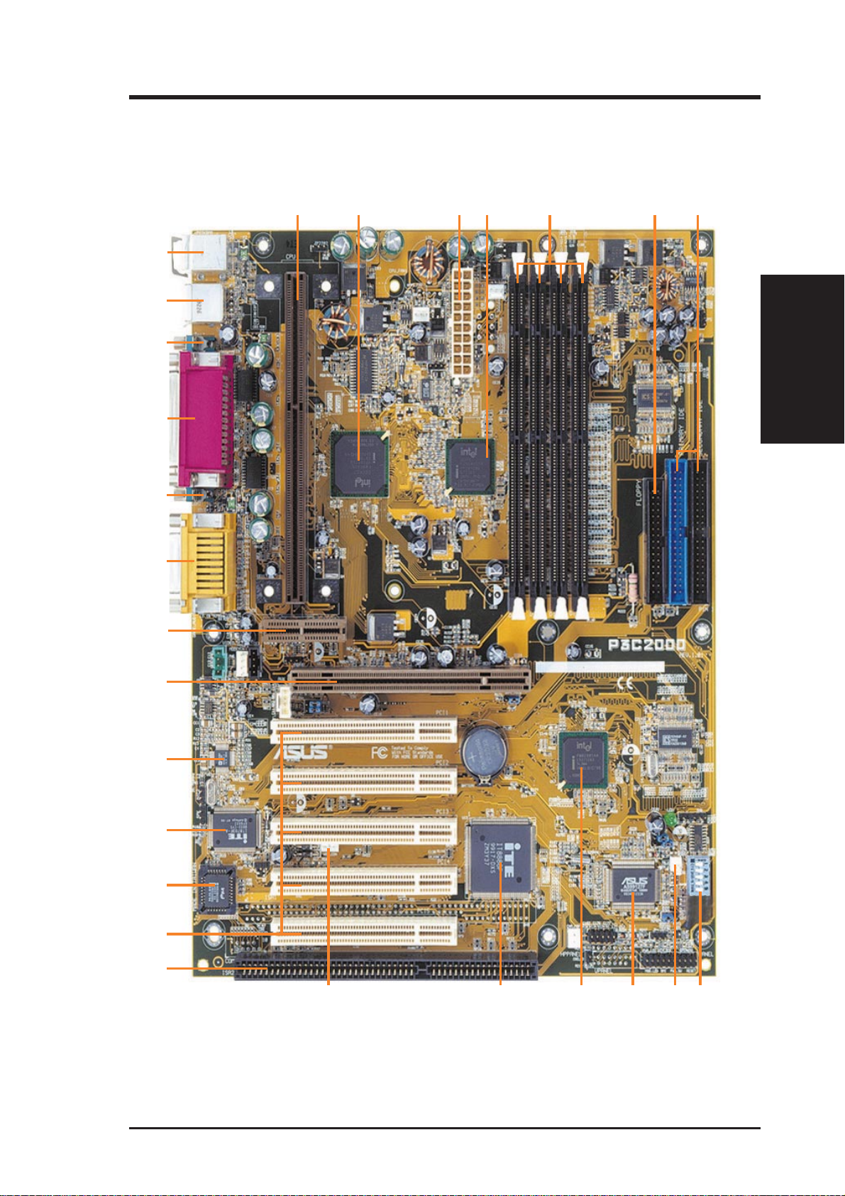
2.2 Motherboard Parts
See opposite page for locations.
1
2
3
Motherboard Parts
2. FEATURES
4
5
6
7
8
9
10
11
2. FEATURES
CPU Slot 1
Intel 820 Memory Controller Hub (MCH)
ATX Power Connector for connection to an ATX power supply
Intel 82805 Memory Translator Hub (MTH) with Heatsink (not shown)
DIMM Sockets
Floppy Disk Drive Connector
Primary (
Feature Setting DIP Switches
Wake-On-Ring Connector
ASUS ASIC with Hardware Monitor
Intel I/O Controller Hub (ICH)
BLUE) and Secondary IDE Connectors
12
PCI-to-ISA Bridge
13
Wake-On-LAN Connector
14
ISA Slot (optional)
15
PCI Slots
16
Four Mbit Firmware Hub (Programmable BIOS)
17
Low Pin Count (LPC) Multi-I/O Chipset
18
Audio CODEC (optional)
19
Accelerated Graphics Port (AGP) Pro Slot
20
Audio Modem Riser Slot
21
Joystick/Midi Connector (
T) (optional) /
Line Out, Line In, Microphone In Connectors (
22
Serial COM1 Port (
23
Parallel Port (
24
Serial COM2 Port (
25
USB Ports (USB1 & USB2)
26
PS/2 Mouse (
T) / PS/2 Keyboard (B) Connector
B)
T)
B)
B) (optional)
T: Top
B: Bottom
12
ASUS P3C2000 User’s Manual
2. FEATURES
2.2 Motherboard Parts...
1
continued
2
26
25
24
23
22
3
4
5
6
7
2. FEATURES
Motherboard Parts
21
20
19
18
17
16
15
14
13
ASUS P3C2000 User’s Manual 13
1112
10
9
8
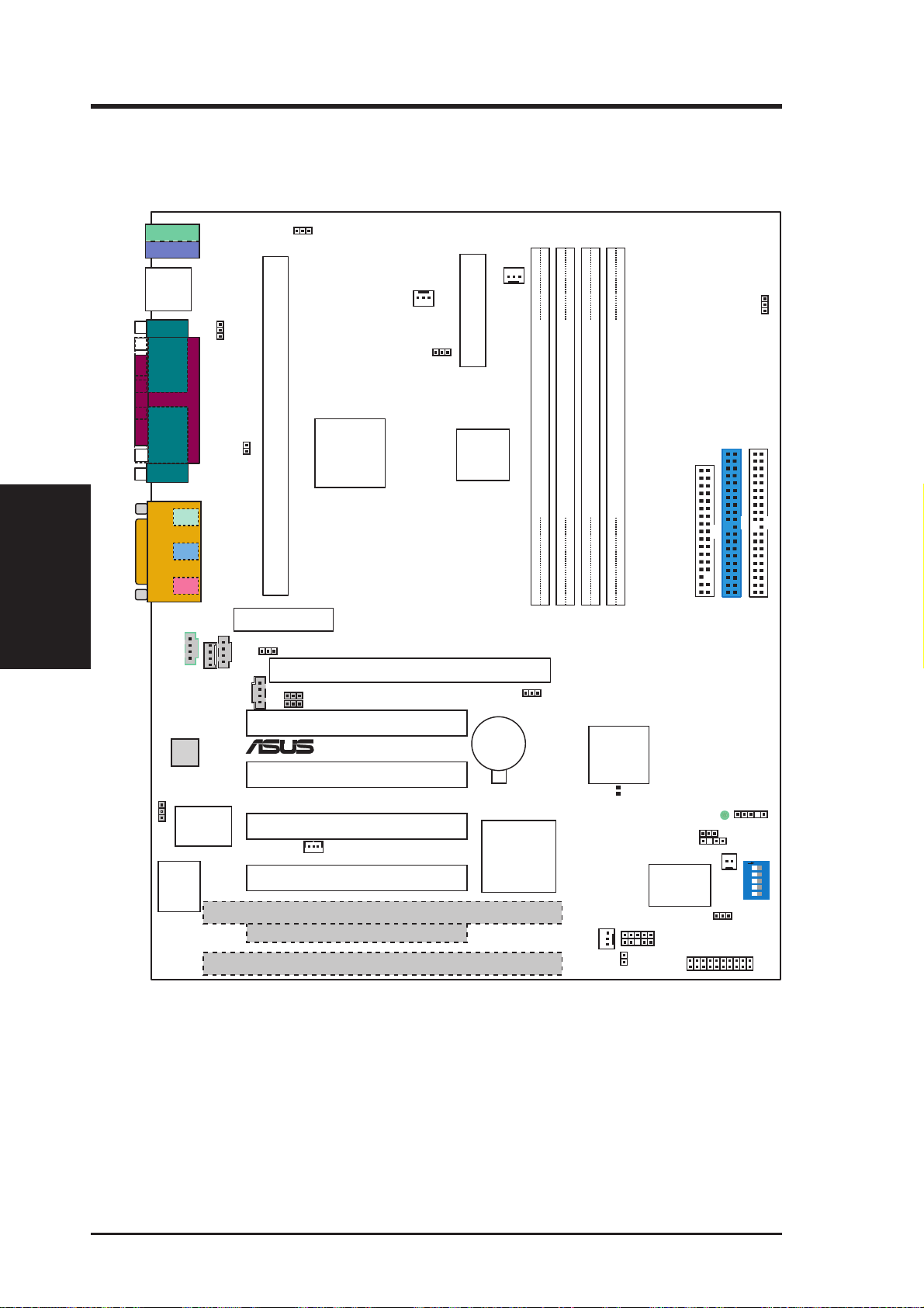
3. HARDWARE SETUP
3.1 Motherboard Layout
T: Top B: Bottom
T: Mouse
B: Keyboard
USB
T: USB1
B: USB2
COM2
PARALLEL PORT
COM1
Motherboard Layout
3. H/W SETUP
Line
Out
Line
In
Mic
GAME_AUDIO
In
VIDEO
Audio
Codec
Count
SPK
Multi I/O
4Mbit
Firmware
Hub
PS2KBMS
MODEM
Low Pin
(LPC)
JP1
JTPWR
OPTIONAL
Audio Modem Riser
ADN#
CD_IN
AUX
JP2702
CPU_FAN1
PWR_FAN
JP3
ATX Power Connector
Slot1 CPU
(AMR)
Intel 820
Memory
Controller
Hub (MCH)
Intel 82805
Memory
Translator
Hub (MTH)
Accelerated Graphics Port (AGP Pro)
AUD_EN1
AUD_EN2
PCI1
®
SAFE_MODE
CR2032 3V
Lithium Cell
CMOS Power
PCI2
PCI3
WOL_CON
PCI4
ISA1
PCI
to ISA
Bridge
PCI5
ISA2
DIMM1 (64/72 bit, 168-pin module)
0 2
Row
DIMM3 (64/72 bit, 168-pin module)
DIMM2 (64/72 bit, 168-pin module)
30
DIMM4 (64/72 bit, 168-pin module)
11
23
Intel I/O
Controller
Hub (ICH)
CLRTC
(R180)
CHA_FAN
IDELED
P3C2000
LED1
JEN
CHASSIS
ASUS
ASIC
with Hardware
Monitor
NO_REBOOT
IR
FLOPPY
WOR
PANEL
PRIMARY
IDE
SMB
JP5
SECONDARY
O
N
12345
IDE
DIP Switches
Grayed midboard items are optional at the time of purchase.
14
ASUS P3C2000 User’s Manual

3. HARDWARE SETUP
3.2 Layout Contents
Motherboard Settings
1) JEN p.18 JumperFree™ Mode (Enable/Disable)
2) JP1 p.18 USB Device Wake Up (Enable/Disable)
3) SAFE_MODE p.19 Safe Mode Setting (Normal/Safe Mode)
4) NO_REBOOT p.19 Automatic T imeout Reboot Setting (Normal/No Reboot)
5) AUD_EN1, AUD_EN2 p.20 Onboard Audio CODEC Setting (Enable/Disable)
6) ADN# p.20 AMR Bus Setting (Enable/Disable)
7) JP5 p.21 Voltage I/O Setting (Enable/Disable)
8) JP2702/JP3 p.21 MCH/MTH Voltage Setting (Enable/Disable)
9) DSW (SW2) p.22 CPU External Frequency Setting
10) CLRTC (R180) p.63 Clear RTC RAM
Expansion Slots
1) DIMM0, DIMM1 p.24 168-Pin System Memory Support
2) CPU p.27 Central Processing Unit (CPU)
3) PCI1, PCI2, PCI3, PCI4, PCI5 p.34 32-bit PCI Bus Expansion Slots
4) AGPPRO p.36 Accelerated Graphics Port (AGP Pro) Slot
5) AMR p.37 Audio Modem Riser Slot
Connectors
1) PS2KBMS p.38 PS/2 Mouse Connector (6-pin female)
2) PS2KBMS p.38 PS/2 Keyboard Connector (6-pin female)
3) USB p.39 Universal Serial Bus Ports 0 & 1 (Two 4-pin female)
4) PARALLEL p.39 Parallel Port Connector (25-pin female)
5) COM1, COM2 p.39 Serial Port COM1/COM2 Connectosr (T wo 9-pin male)
6) GAME_AUDIO p.40 Joystick/MIDI Connector (15-pin female) (optional)
7) GAME_AUDIO p.40 Audio Port Connectors (Three 1/8” female) (optional)
8) CHASSIS p.40 Chassis Intrusion Connector (4-1 pins)
9) PRIMARY/SECONDAR Y IDE p.41 Primary/Secondary IDE Connectors (Two 40-1pins)
3. H/W SETUP
Layout Contents
10) FLOPPY p.41 Floppy Disk Drive Connector (34-1pins)
11) WOL_CON p.42 Wake-On-LAN Connector (3 pins)
12) WOR p.42 Wake-On-Ring Connector (2 pins)
13) IDELED p.43 IDE Activity LED (2 pins)
14) CPU_FAN1, PWR_FAN p.43 CPU, Power Supply , Chassis Fan Connectors (Three 3-pin)
CHA_F AN
ASUS P3C2000 User’s Manual 15

3. HARDWARE SETUP
15) CD_IN, AUX, p.44 Internal Audio Connectors (Four 4-pins) (optional)
VIDEO, MODEM
16) IR p.44 Serial and Consumer Infrared Module Connector (5-pin)
17) SPK p.45 Internal Speaker Connector (Two 2-pin)
18) ATXPWR p.45 ATX Power Supply Connector (20 pins)
19) SMB p.46 SMBus Connector (5-1 pins)
20) JTPWR p.46 Power Supply Thermal Sensor Connector (2 pins)
21) PLED (PANEL) p.48 System Power LED Lead (3-1 pins)
22) KEYLOCK (PANEL) p.48 Keyboard Lock Switch Lead (2 pins)
23) SPEAKER (PANEL) p.48 System Warning Speaker Connector (4 pins)
24) LED (PANEL) p.48 System Message LED (2 pins)
25) SMI (PANEL) p.48 System Management Interrupt Switch Lead (2 pins)
26) PWRSW (PANEL) p.48 ATX Power / Soft-Off Switch Lead (2 pins)
3. H/W SETUP
27) RESET (PANEL) p.48 Reset Switch Lead (2 pins)
16 ASUS P3C2000 User’s Manual

3. HARDWARE SETUP
3.3 Hardware Setup Procedure
Before using your computer, you must complete the following steps:
• Check Motherboard Settings
• Install Memory Modules
• Install the Central Processing Unit (CPU)
• Install Expansion Cards
• Connect Ribbon Cables, Panel Wires, and Power Supply
3.4 Motherboard Settings
WARNING! Computer motherboards and expansion cards contain very delicate
Integrated Circuit (IC) chips. To protect them against damage from static electricity, you should follow some precautions whenever you work on your computer.
1. Unplug your computer when working on the inside.
2. Use a grounded wrist strap before handling computer components. If you do
not have one, touch both of your hands to a safely grounded object or to a metal
object, such as the power supply case.
3. Hold components by the edges and try not to touch the IC chips, leads or connectors, or other components.
4. Place components on a grounded antistatic pad or on the bag that came with the
component whenever the components are separated from the system.
5. Ensure that the ATX power supply is switched off before you plug in or
remove the ATX power connector on the motherboard.
Motherboard Feature Settings
The motherboard’s onboard functions are either adjusted through jumpers or DIP
switches. When using DIP switches, the white block represents the switch’s position. The example below shows all the switches in the OFF position.
SW2
ON
12345
P3C2000
®
1. Frequency Selection
2. Frequency Selection
3. Frequency Selection
4. Frequency Selection
5. Frequency Selection
3. H/W SETUP
Motherboard Settings
P3C2000 DIP Switches
ASUS P3C2000 User’s Manual 17
ONOFF
3. HARDWARE SETUP
1) JumperFree™ Mode (JEN)
This jumper allows you to enable or disable the JumperFree™ mode. The
JumperFree™ mode allows processor settings to be made through the BIOS
setup (see 4.4 Advanced Menu).
NOTE: In JumperFree™ mode, all dip switches (DSW) must be set to OFF.
Setting JEN
Enable (JumperFree) [2-3] (default)
Disable (Jumper) [1-2]
JP5
Motherboard Settings
3. H/W SETUP
P3C2000 JumperFree™ Mode Setting
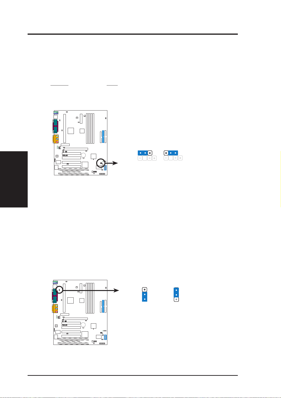
2) USB Device Wake Up (3-pin JP1)
This allows you to disable or enable the USB device power up function. Set this
jumper to Enable if you wish to use your USB device to wake up your computer .
This feature requires an ATX power supply that can supply at least 2A on the
+5VSB lead. The default is set to Disable because not all computers have the
appropriate ATX power supply. Your computer will not power ON if you set this
to Enable and do not have the appropriate ATX power supply. NOTE: This
jumper must be set in conjunction with Wake On USB Device in 4.5.1 Power Up
Control (4. BIOS SETUP).
NOTE: For suspend to RAM function, this jumper must be set to Enable.
123
JEN
123
(Default)
30
P3C2000
®
Jumper JumperFree
JP1
3
2
1
+5V
30
P3C2000
®
(Default)
3
2
1
+5VSB
(Enable USB
Device Wake Up)
P3C2000 USB Device Wake Up
18 ASUS P3C2000 User’s Manual
3. HARDWARE SETUP
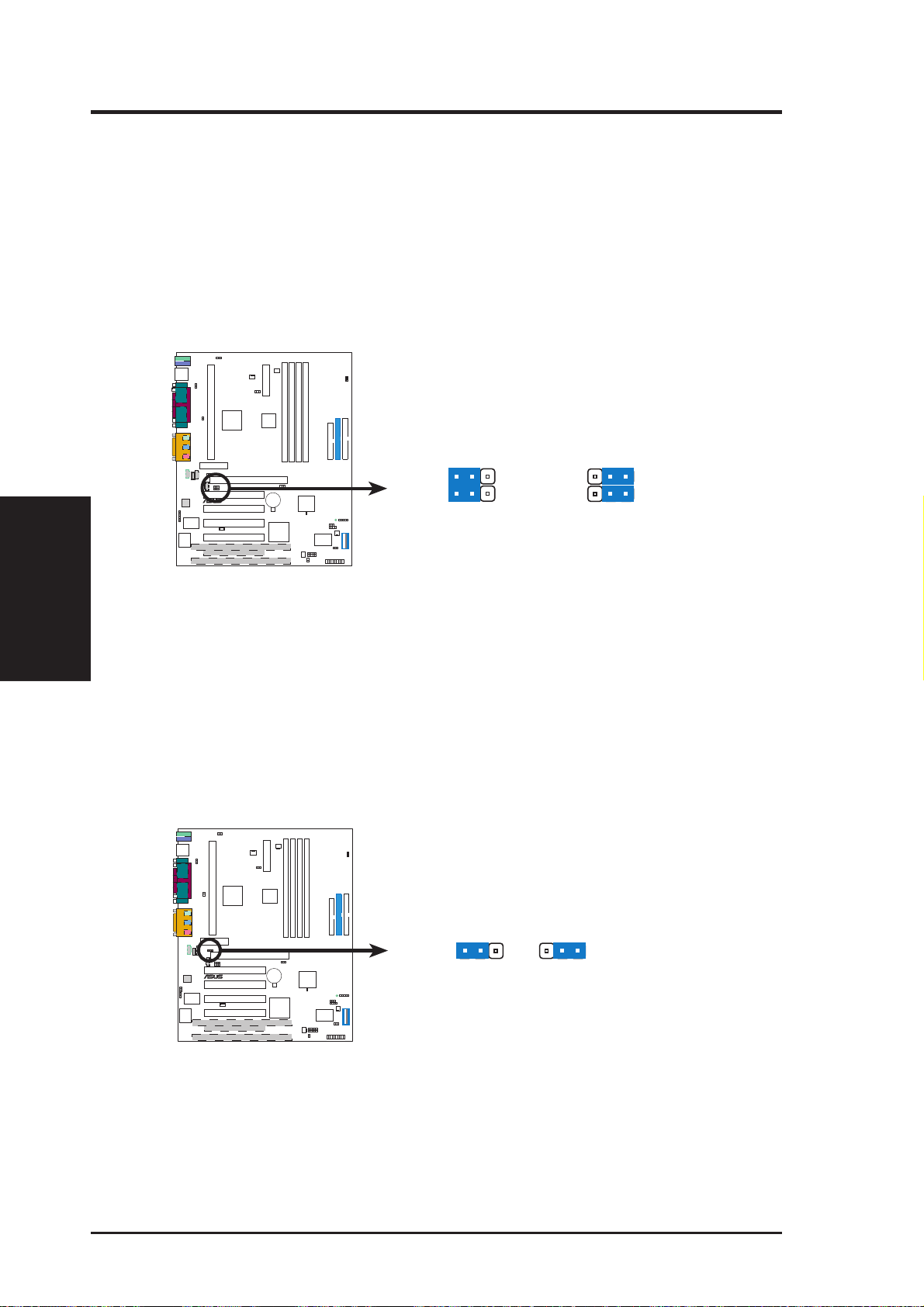
3) Safe Mode Setting (SAFE_MODE)
Usually Slot 1 processors have locked frequency multiples. In this case, there is
no way to exceed the specified multiple whether through motherboard settings or
BIOS setup. W ith unlocked Slot 1 processors, exceeding the specified multiple is
possible through BIOS setup. Exceeding the specified multiple may result in hanging during bootup. If this occurs, enable Safe Mode to force a multiple of 2 and
100MHz FSB to enter BIOS setup to correct the problem.
Setting SAFE_MODE
Normal [2-1] (default)
Safe Mode [3-2]
30
P3C2000
®
SAFE_MODE
1
3
2
Normal
(Default)
Safe Mode
321
P3C2000 Safe Mode Setting
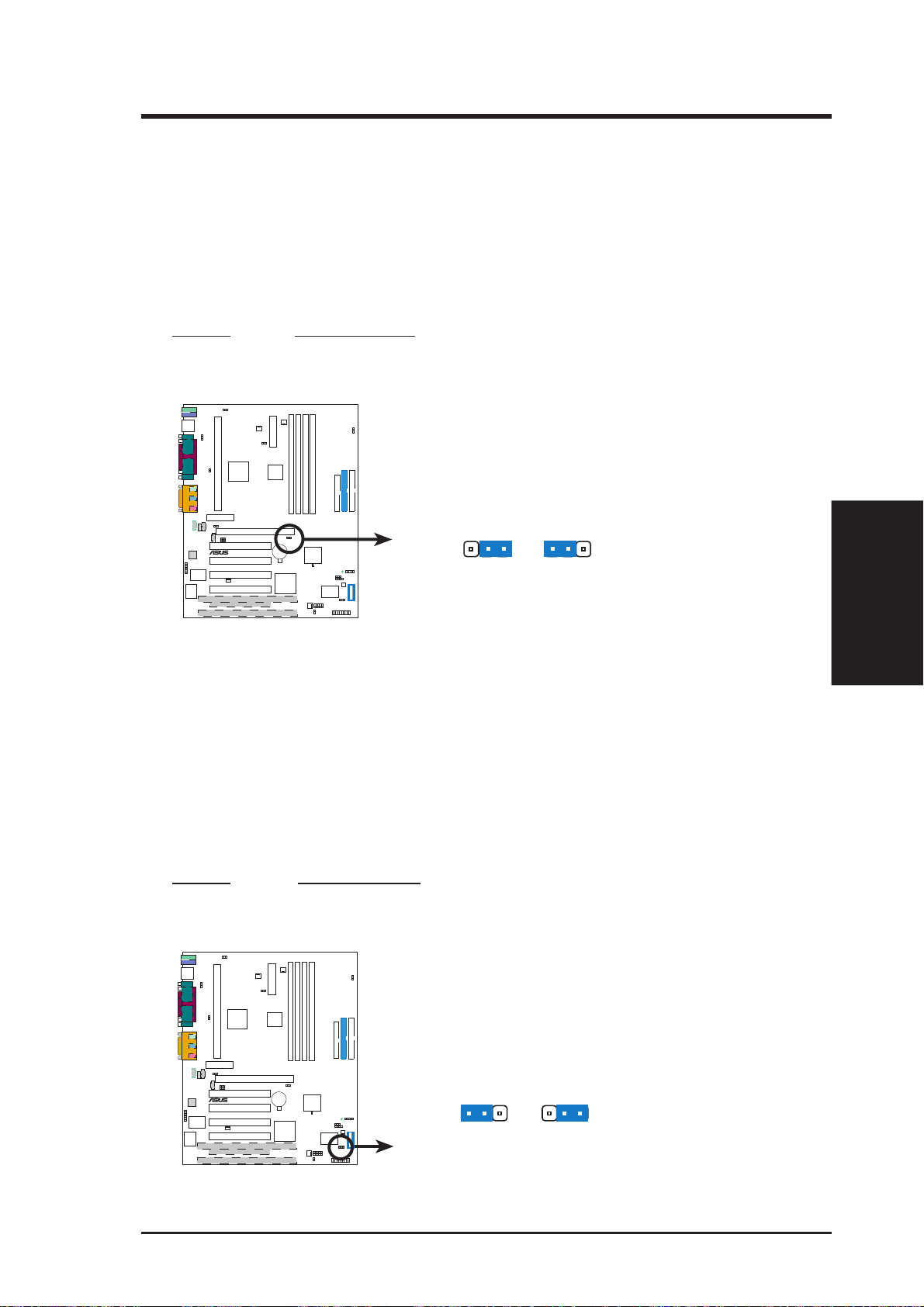
4) Automatic Timeout Reboot Setting (NO_REBOOT)
The motherboard is set so that when the BIOS detects a hang (timeout) during
bootup, the motherboard will automatically reboot. If rebooting is repeating ineffectively, set this jumper to No Reboot to disable auto-reboot. However, if
Safe Mode Setting (SAFE_MODE) is set to Safe Mode, setting Automatic
Timeout Reboot Setting (NO_REBOOT) to No Reboot will bring the system
to Safe Mode so you may be able to correct any problems.
Setting NO_REBOOT
Normal [1-2] (default)
No Reboot [2-3]
3. H/W SETUP
Motherboard Settings
30
P3C2000
®
P3C2000 Reboot Setting
ASUS P3C2000 User’s Manual 19
NO_REBOOT
3
1
2
Normal
(Default)
No Reboot
123
3. HARDWARE SETUP
5) Onboard Audio CODEC Setting (AUD_EN1 / AUD_EN2)
(available on audio model only)
The onboard audio CODEC may be enabled or disabled using all of these jumpers. Disable the onboard audio CODEC if you are using an ISA or PCI audio
card on any of the expansion slots or a primary AMR on the AMR slot (see AMR
Slot later in this section). If using an ISA or PCI audio expansion card, On-
board AC97 Audio Controller in 4.4.2 I/O Device Configuration must also be
disabled.
JP5
Motherboard Settings
3. H/W SETUP
P3C2000 Audio Codec Setting
6) AMR Bus Setting (ADN#)
This jumper allows you to select the AMR bus to be Primary Codec or Secondary Codec. If onboard audio codec is enabled, Secondary Codec must be se-
lected; otherwise, select Primary Codec if the onboard audio CODEC is disabled.
30
P3C2000
®
123
AUD_EN1
AUD_EN2
123
AUD_EN1
AUD_EN2
DisableEnable
(Default)
JP5
ADN#
30
P3C2000
®
123
Secondary
Codec
(Default)
123
Primary
Codec
P3C2000 AMR Bus Setting
20 ASUS P3C2000 User’s Manual
3. HARDWARE SETUP
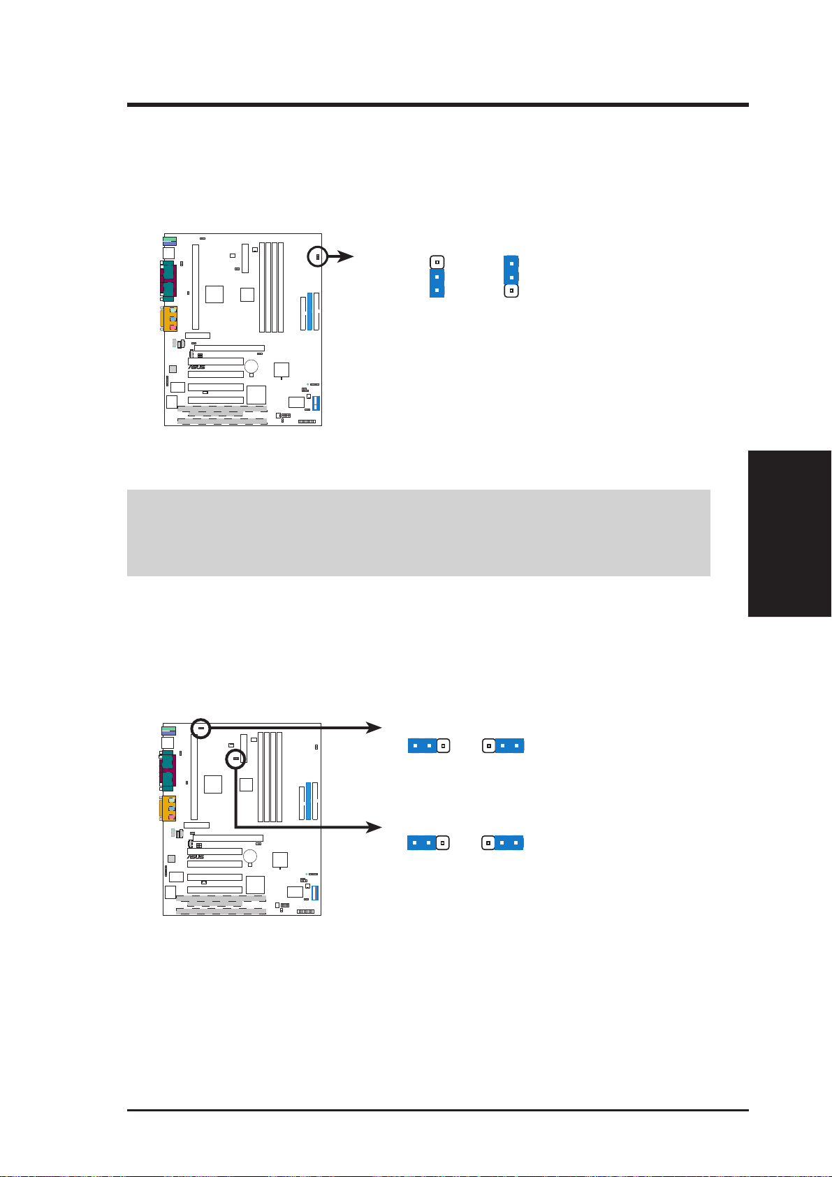
7) Voltage I/O Setting (JP5)
This jumper allows you to select the voltage supplied to the DRAM, chipset,
AGP, and PCI . The default setting of Normal should be used unless processor
overclocking requires a higher voltage (Test).
JP5
3
2
1
Normal
30
P3C2000
®
(Default)
P3C2000 Input/Output Voltage Setting
3
2
1
Test
WARNING! Using a higher voltage may help when overclocking but may result
in the shortening of your computer component’s life. It is highly recommended
that you leave this setting on its default.
8) MCH/MTH Voltage Selection (JP2702 / JP3)
These jumpers allow you to select the voltage supplied to the CPU’ s I/O buf fer.
The default setting of Normal should be used unless processor overclocking
requires a higher voltage (Test).
JP2702 (MCH)
123
Normal
(Default)
30
P3C2000
®
JP3 (MTH)
123
Normal
(Default)
123
Test
123
Test
3. H/W SETUP
Motherboard Settings
P3C2000 MCH/MTH Voltage Selection
ASUS P3C2000 User’s Manual 21
3. HARDWARE SETUP
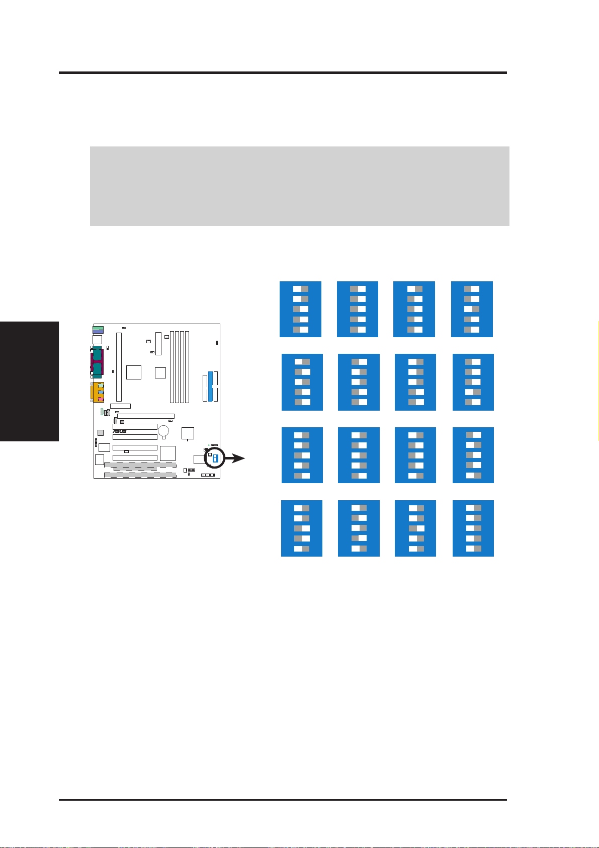
9) CPU External Frequency Setting (DSW-1, -2, -3, -4, -5)
This option tells the clock generator what frequency to send to the CPU and the
PCI bus. This allows the selection of the CPU’s External frequency.
IMPORTANT:
1. In JumperFree mode, all dip switches (DSW-1–DSW-5) must be set to OFF.
2. When JumperFree mode is enabled, use BIOS setup in place of these switches
(see CPU Speed in Advanced Menu in BIOS Setup).
NOTE: Only selected switches are illustrated. For a complete frequency listing,
see next page.
Motherboard Settings
3. H/W SETUP
®
P3C2000 CPU External
Clock (BUS) Frequency
Selection
P3C2000
SW2
CPU
CPU→ 112.0MHz 114.0MHz109MHz
CPU→ 125.00MHz 133.0MHz120MHz
CPU→ 150.0MHz 168MHz142.0MHz
12345
→
12345
12345
12345
ON
103.0MHz 105.0MHz100.0MHz
ON
ON
ON
ON
12345ON12345
ON
12345
ON
12345
ON
12345
ON
12345
ON
12345
ON
12345
(JumperFree Mode)
ON
12345
107.0MHz
ON
12345
116.0MHz
ON
12345
138.0MHz
ON
12345
180MHz
NOTE: If your processor does not have a locked Frequency Multiple, you must
use CPU Core:Bus Fr eq. Multiple in 4.4 Advanced Menu of the BIOS setup to
set the Frequency Multiple. If the Frequency Multiple is locked, setting the Frequency Multiple in BIOS setup will have no effect.
22 ASUS P3C2000 User’s Manual

3. HARDWARE SETUP
External Frequency Table
The following table is for use by experienced motherboard installers only . Overclocking
can result in system instability or even shortening the life of the processor .
CPU Frequency Selection Switches
(MHz) 1 2 3 4 5
103 [ON ] [ON ] [ON] [ON] [ON ]
105 [OFF] [O N ] [O N ] [O N ] [O N ]
100 [OFF] [OFF] [O N ] [O N ] [O N ]
107 [ON ] [O N ] [OFF] [O N ] [O N ]
109 [OFF] [O N ] [OFF] [O N ] [O N ]
112 [O N] [OFF] [OFF] [O N ] [O N ]
114 [OFF] [OFF] [OFF] [O N ] [O N ]
116 [O N] [O N ] [O N ] [OFF] [O N ]
118 [OFF] [ON] [ON] [OFF] [ON]
120 [OFF] [OFF] [O N ] [OFF] [O N ]
122 [ON] [ON] [OFF] [OFF] [ON]
125 [OFF] [O N ] [OFF] [OFF] [O N ]
128 [ON] [OFF] [OFF] [OFF] [ON]
130 [OFF] [OFF] [OFF] [OFF] [ON]
133 [OFF] [O N ] [O N ] [O N ] [OFF]
138 [ON] [OFF] [ON] [ON] [OFF]
142 [OFF] [OFF] [O N ] [O N ] [OFF]
146 [ON] [ON] [OFF] [ON] [OFF]
150 [OFF] [O N ] [OFF] [O N ] [OFF]
153 [ON] [OFF] [OFF] [ON] [OFF]
156 [OFF] [OFF] [OFF] [ON] [OFF]
159 [ON] [ON] [ON] [OFF] [OFF]
162 [OFF] [ON] [ON] [OFF] [OFF]
165 [ON] [OFF] [ON] [OFF] [OFF]
168 [OFF] [OFF] [O N ] [OFF] [OFF]
171 [ON] [ON] [OFF] [OFF] [OFF]
174 [OFF] [ON] [OFF] [OFF] [OFF]
177 [ON] [OFF] [OFF] [OFF] [OFF]
180 [OFF] [OFF] [OFF] [OFF] [OFF]
3. H/W SETUP
Motherboard Settings
For updated processor settings, visit ASUS’s web site (see ASUS CONTACT INFORMATION)
ASUS P3C2000 User’s Manual 23

3.5 System Memory (DIMM)
NOTE: No hardware or BIOS setup is required after adding or removing memory.
This motherboard uses only Dual Inline Memory Modules (DIMMs). Sockets are
available for 3.3Volt (power level) unbuffered Synchronous Dynamic Random Ac-
cess Memory (SDRAM) of 64, 128, 256, or 512MB with Serial Presence Detect (SPD).
This chipset does not support ECC. However, ECC memory modules may still be
used, but the ECC function will not be available.
Memory speed setup is recommended through SDRAM Configuration in 4.4.1
Chip Configuration.
IMPORTANT:
1. This motherboard’s chipset only supports 64Mbit and 128Mbit SDRAMs
System Memory
3. H/W SETUP
2. If more than one socket will be populated with DIMMs, the first socket in the
3. HARDWARE SETUP
(see SDRAM Configurations).
32Mx4 128 Mbit support is for registered DIMMs only.
4Mx16 64 Mbit support is for unbufferred DIMMs only.
order must be populated with higher-sized DIMMs (in MB). For example,
DIMM1 ≥ DIMM3 ≥ DIMM2 ≥ DIMM4. T otal memory size (in MB), how-
ever, of DIMM2 and DIMM4 must not be greater than DIMM1 and DIMM3
(DIMM1 + DIMM3 ≥ DIMM2 + DIMM4).
SDRAM Configurations
Technology Configuration No. of Row No. of Col. No. of Bank Page
Address Bits Address Bits Address Bits Size
64Mbit 8Mx8 12 9 2 4KB
64Mbit 4Mx16 12 8 2 2KB
128Mbit 32Mx4 12 11 2 16KB
128Mbit 16Mx8 12 10 2 8KB
3.5.1 General DIMM Notes
• This motherboard only supports SPD DIMMs.
• SDRAM chips are generally thinner with higher pin density than EDO (Extended
Data Output) chips.
• BIOS shows SDRAM memory on bootup screen.
• Single-sided DIMMs come in 32, 64,128MB; double-sided come in 64, 128, 256,
512MB.
24 ASUS P3C2000 User’s Manual

3. HARDWARE SETUP
Install memory in any of the following sample combinations (for more possible
combinations, refer to the next table, Possible DIMM Combinations):
Current Memory DIMM1 DIMM2 DIMM3 DIMM4
DIMMs* Size (Rows 0&1) (Rows 2&3) (Rows 1&0) (Rows 3&2)
1 SS SS — — —
1 DS DS — — —
2 SS SS — SS —
2 DS DS DS — —
1 SS / 1DS DS/2>SS DS SS — —
SS>DS/2 SS DS — —
3 SS SS SS SS —
x
3 DS
2 SS / 1DS DS/2>SS DS SS — SS
SS>DS/2 SS DS SS —
2 DS / 1 SS
x
4 SS SS SS SS SS
x
4 DS
3 SSx / 1DS DS/2>SS DS SS — SS
SS>DS/2 SS DS SS —
2 SS / 2 DS DS DS — —
1 SSx / 3 DS DS DS — —
DS DS — —
DS DS — —
DS DS — —
DS SS — SS
SS DS SS —
SS DS — —
SS SS — —
DS SS — —
3. H/W SETUP
System Memory
DS: Double Sided DIMM; SS: Single Sided DIMM; —: Empty
*Current DIMMs means the available DIMMs that you have. Y ou may have to give up one or two DIMMs
due to the limitations indicated on the previous page (see IMPORTANT).
x
Give up one or two of this DIMM.
Possible DIMM Combinations
NOTE: When installing memory, follow first the combinations in Table 1. If you
need more, you may use the combinations in Table 1 with those in Table 2. In any
case, make sure that the notes in IMPORTANT, previous page, are considered.
Table1
DIMM1 (Rows 0&1) DIMM3 (Rows 1&0)
DS —
SS —
SS SS
—DS
—SS
——
Table 2
DIMM2 (Rows 2&3 DIMM4 (Rows 3&2)
DS —
SS SS
SS —
—DS
—SS
——
ASUS P3C2000 User’s Manual 25
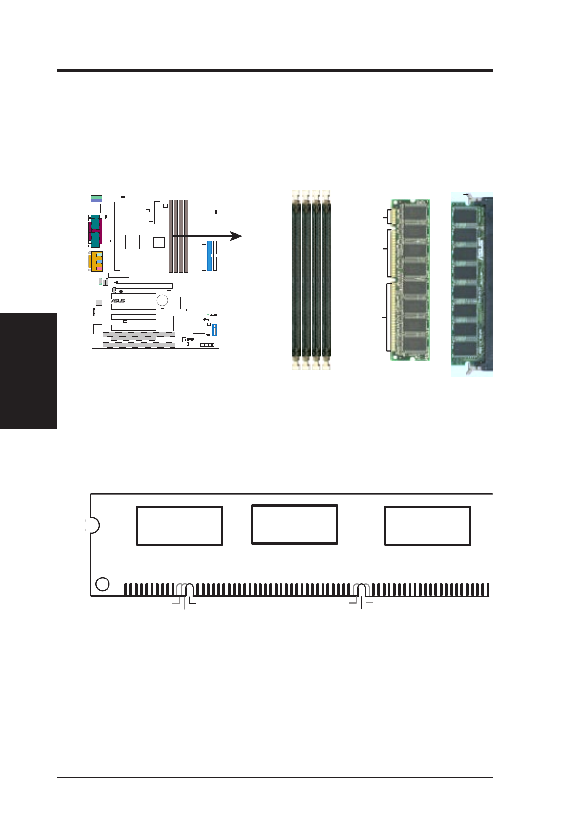
3.5.2 DIMM Installation
Insert the module(s) as shown. Because the number of pins are different on either
side of the breaks, the module will only fit in the orientation shown. DIMMs are
longer and have different pin contact on each side and therefore have a higher pin
density. SIMMs have the same pin contact on both sides.
System Memory
3. H/W SETUP
3. HARDWARE SETUP
Lock
20 Pins
60 Pins
30
P3C2000
®
88 Pins
P3C2000 168-Pin DIMM Sockets
The DIMMs must be 3.3V Unbuffered for this motherboard. To determine the DIMM
type, check the notches on the DIMMs (see figure below).
168-Pin DIMM Notch Key Definitions (3.3V)
DRAM Key Position
RFU
Buffered
Unbuffered
Voltage Key Position
5.0V
Reserved
3.3V
The notches on the DIMM module will shift between left, center, or right to identify
the type and also to prevent the wrong type from being inserted into the DIMM slot
on the motherboard. You must ask your retailer the correct DIMM type before purchasing. This motherboard supports four clock signals per DIMM slot.
26 ASUS P3C2000 User’s Manual
3. HARDWARE SETUP
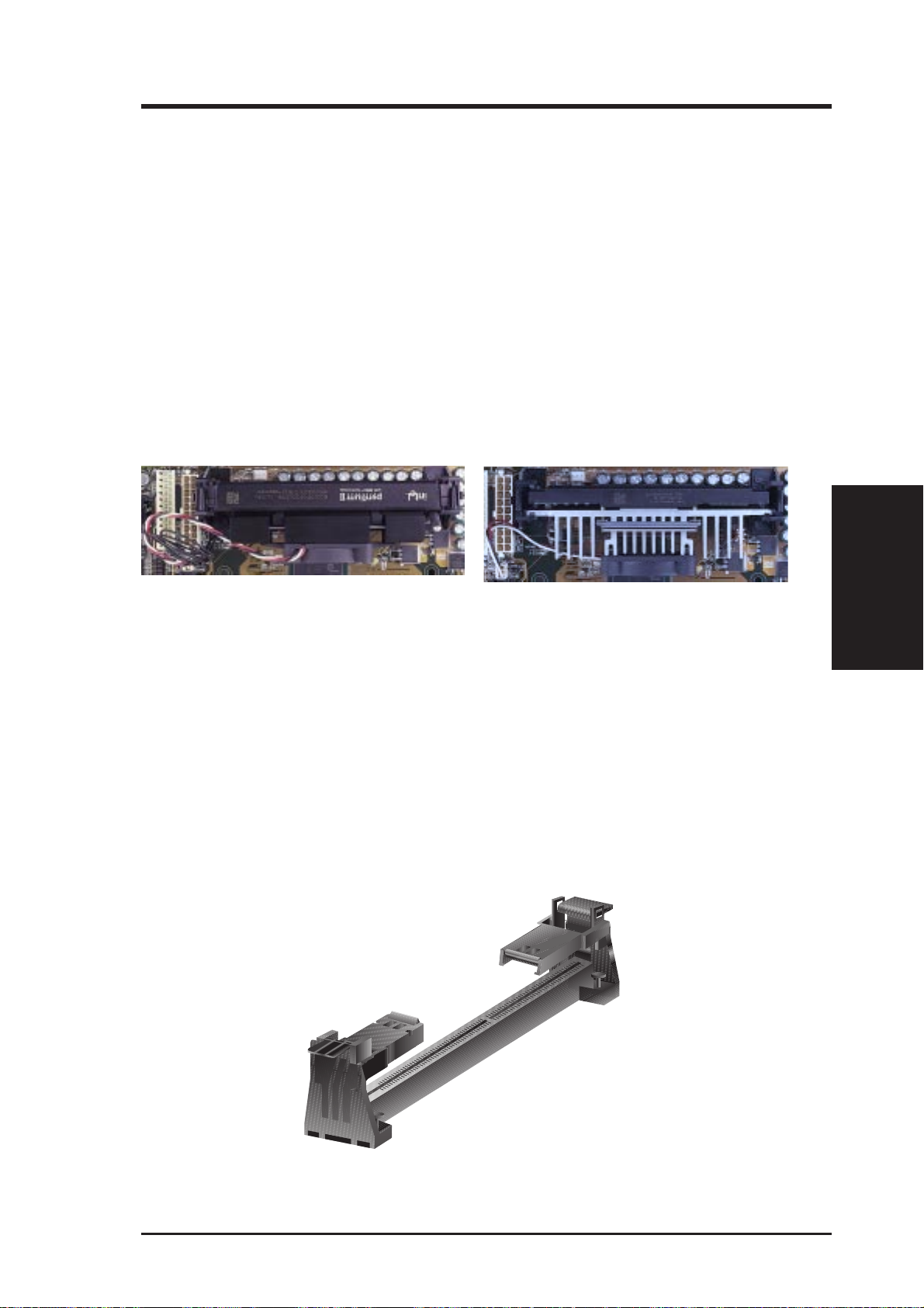
3.6 Central Processing Unit (CPU)
NOTE: The following pictures are provided for reference purposes only. The appearance of your retention mechanism and fan may be different from the following
examples.
Your motherboard provides a Slot 1 connector for a Pentium
aged in a Single Edge Contact Cartridge (SECC2), a Pentium
®
III processor pack-
®
II processor packaged in SECC2/SECC, or a Celeron™ processor packaged in a Single Edge Processor Package (SEPP). An ASUS S370 Series CPU card can allow Socket 370 processors to be used on any ASUS motherboard with the Slot 1 connector (See 7.2 S370
Series CPU Card for instructions on using this card).
Pentium II processor packaged in an SECC with
heatsink and fan (top view)
Pentium III (in an SECC2) with heatsink and fan
NOTE: The SEPP fan (for Celeron processors) is
similar to SECC2 fan except that the clamping
design is different.
CPU
3. H/W SETUP
3.6.1 Universal Retention Mechanism
Your motherboard may come preinstalled with a Universal Retention Mechanism
(URM). The URM, which supports Pentium III / II and Celeron processors, may be
the folding or non-folding type. Shown below is the folding type.
Folding Universal Retention Mechanism (URM)
ASUS P3C2000 User’s Manual 27

3. HARDWARE SETUP
3.6.2 Heatsinks
The recommended heatsinks (see section on recommended heatsinks for Pentium
III / II processors for more information) for the boxed Pentium III / II and Celeron
processors are those with three-pin fans that can be connected to the fan connectors
on the motherboard.
WARNING! Be sure that there is sufficient air circulation across the processor’s
heatsink by regularly checking that your CPU fan is working. W ithout sufficient
circulation, the processor could overheat and damage both the processor and the
motherboard. You may install an auxiliary chassis fan, if necessary.
3.6.3 Installing the Processor
3. H/W SETUP
CPU
NOTE: The following assumes that your motherboard came with a folding URM.
1. Unlock the URM’ s Folding Support
Arms: The folding support arms of
the URM are locked when shipped.
Locked Folding Support
T o unlock the support arms, simply flip
them up to an upright position.
The URM is now ready for the installation of your processor.
28 ASUS P3C2000 User’s Manual
Unlocked Folding Support
3. HARDWARE SETUP
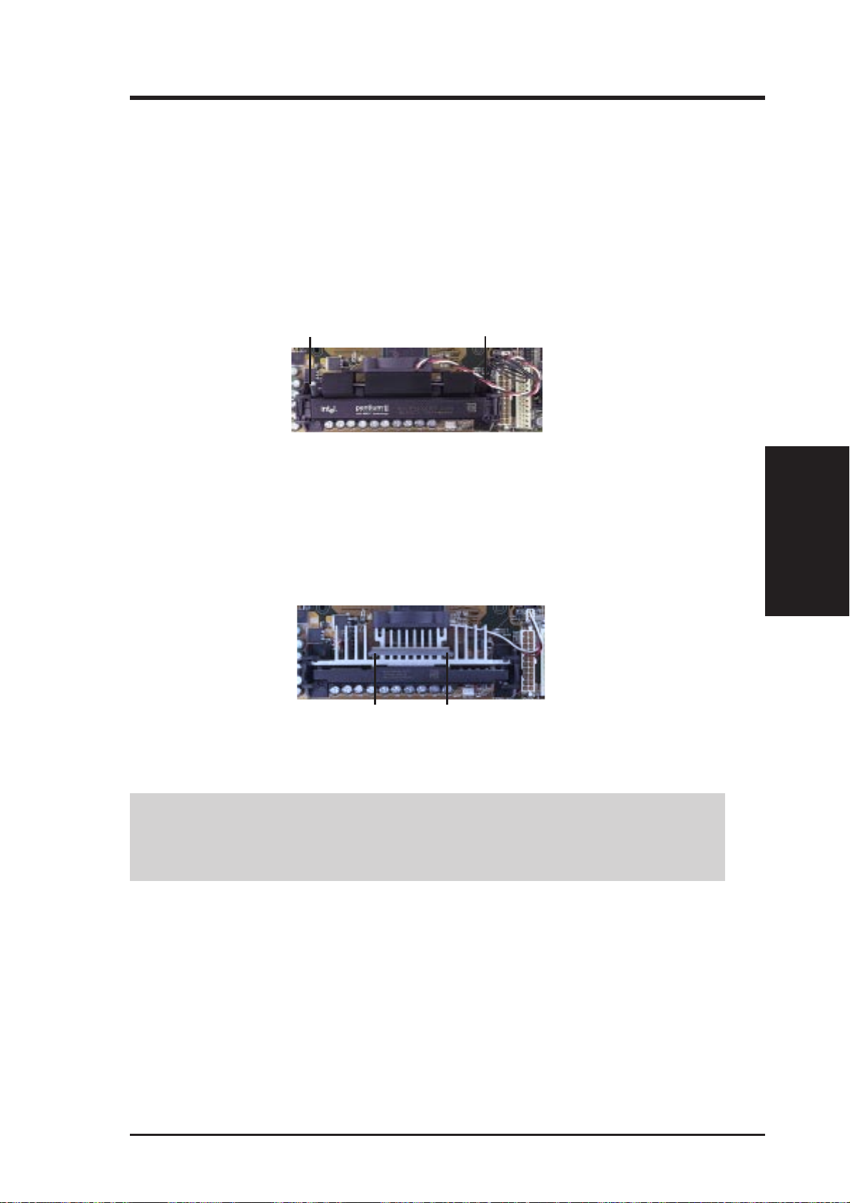
2. Attach the Heatsink
NOTE: If provided, you should follow the heatsink attachment instructions
that came with your heatsink or processor. The following steps are provided
only as a general guide and may not reflect those for your heatsink.
Using SECC fan with Pentium
®
II
Push the two lock arms one direction to clamp the heatsink onto the processor and
the other direction to release.
Lock Arm
Using SECC2 fan with Pentium
®
III
Lock Arm
Insert the four heatsink’s pins through the holes of the SECC2. Place the metal clip
on the ends of the pins and slide until it locks into place.
CPU
3. H/W SETUP
Four Pins and metal clip
W ARNING! Make sure the heatsink is mounted tightly against the SECC2, SECC,
or SEPP; otherwise, the CPU will overheat. You may install an auxiliary fan to
provide adequate circulation across the processor’s passive heatsink.
NOTE: The SEPP heatsink and fan (for Intel Celeron processors) is similar to
the SECC2 heatsink and fan except that the clamping design is different.
ASUS P3C2000 User’s Manual 29

3. HARDWARE SETUP
3. Insert the SECC2/SECC/SEPP
3. H/W SETUP
CPU
SECC with Pentium
®
II only: Push the SECC’s two locks inward until you hear
a click (the picture in step 2 shows the locks in the outward position and inward in
the picture below).
With the heatsink facing the motherboard’s chipset, push the SECC2, SECC, or
SEPP gently but firmly into the Slot 1 connector until it is fully inserted.
SECC2/SEPP
Push lock inward
CPU fan cable to
fan connector
CPU fan cable to
fan connector
4. Secure the SECC2/SECC/SEPP
Secure the SECC2/SECC/SEPP in place by pushing the SECC2/SECC/SEPP
until it is firmly seated on the Slot 1 connector.
SECC with Pentium
®
II only: The SECC locks should be outward when se-
cured so that the lock shows through the retention mechanism’s lock holes.
SECC SECC2/SEPP
Lock hole
Lock hole
CPU fan cable to
fan connector
CPU fan
cable to fan
connector
30 ASUS P3C2000 User’s Manual
 Loading...