

ASUS MEL User Manual

R
MEL
Socket 370 Motherboard
USER’S MANUAL

USER'S NOTICE
No part of this manual, including the products and software described in it, may be reproduced, transmitted, transcribed, stored in a retrieval system, or translated into any language in
any form or by any means, except documentation kept by the purchaser for backup purposes,
without the express written permission of ASUSTeK COMPUTER INC. (“ASUS”).
ASUS PROVIDES THIS MANUAL “AS IS” WITHOUT WARRANTY OF ANY KIND,
EITHER EXPRESS OR IMPLIED, INCLUDING BUT NOT LIMITED T O THE IMPLIED
WARRANTIES OR CONDITIONS OF MERCHANTABILITY OR FITNESS FOR A PARTICULAR PURPOSE. IN NO EVENT SHALL ASUS, ITS DIRECTORS, OFFICERS,
EMPLOYEES OR AGENTS BE LIABLE FOR ANY INDIRECT, SPECIAL, INCIDENTAL, OR CONSEQUENTIAL DAMAGES (INCLUDING DAMAGES FOR LOSS OF
PROFITS, LOSS OF BUSINESS, LOSS OF USE OR DATA, INTERRUPTION OF BUSINESS AND THE LIKE), EVEN IF ASUS HAS BEEN ADVISED OF THE POSSIBILITY
OF SUCH DAMAGES ARISING FROM ANY DEFECT OR ERROR IN THIS MANUAL
OR PRODUCT.
Product warranty or service will not be extended if: (1) the product is repaired, modified or
altered, unless such repair, modification of alteration is authorized in writing by ASUS; or (2)
the serial number of the product is defaced or missing.
Products and corporate names appearing in this manual may or may not be registered trademarks or copyrights of their respective companies, and are used only for identification or
explanation and to the owners’ benefit, without intent to infringe.
• Intel, LANDesk, and Pentium are registered trademarks of Intel Corporation.
• IBM and OS/2 are registered trademarks of International Business Machines.
• Symbios is a registered trademark of Symbios Logic Corporation.
• Windows and MS-DOS are registered trademarks of Microsoft Corporation.
• Adobe and Acrobat are registered trademarks of Adobe Systems Incorporated.
The product name and revision number are both printed on the product itself. Manual revi-
sions are released for each product design represented by the digit before and after the period
of the manual revision number. Manual updates are represented by the third digit in the manual
revision number.
For previous or updated manuals, BIOS, drivers, or product release information, contact ASUS
at http://www.asus.com.tw or through any of the means indicated on the following page.
SPECIFICATIONS AND INFORMATION CONTAINED IN THIS MANUAL ARE FURNISHED FOR INFORMATIONAL USE ONLY, AND ARE SUBJECT TO CHANGE AT
ANY TIME WITHOUT NOTICE, AND SHOULD NOT BE CONSTRUED AS A COMMITMENT BY ASUS. ASUS ASSUMES NO RESPONSIBILITY OR LIABILITY FOR
ANY ERRORS OR INACCURACIES THAT MA Y APPEAR IN THIS MANUAL, INCLUDING THE PRODUCTS AND SOFTWARE DESCRIBED IN IT.
Copyright © 1999 ASUSTeK COMPUTER INC. All Rights Reserved.
Product Name: ASUS MEL
Manual Revision: 1.01 E335
Release Date: March 1999
2 ASUS MEL User’s Manual

ASUS CONTACT INFORMATION
ASUSTeK COMPUTER INC. (Asia-Pacific)
Marketing
Address: 150 Li-Te Road, Peitou, Taipei, T aiwan 112
Telephone: +886-2-2894-3447
Fax: +886-2-2894-3449
Email: info@asus.com.tw
Technical Support
Tel (English): +886-2-2894-3447 ext. 706
Tel (Chinese): +886-2-2894-3447 ext. 701
Fax: +886-2-2895-9254
Email: tsd@asus.com.tw
Newsgroup: news2.asus.com.tw
WWW: www.asus.com.tw
FTP: ftp.asus.com.tw/pub/ASUS
ASUS COMPUTER INTERNATIONAL (America)
Marketing
Address: 6737 Mowry Avenue, Mowry Business Center, Building 2
Newark, CA 94560, USA
Fax: +1-510-608-4555
Email: info-usa@asus.com.tw
Technical Support
Fax: +1-510-608-4555
BBS: +1-510-739-3774
Email: tsd-usa@asus.com.tw
WWW: www.asus.com
FTP: ftp.asus.com.tw/pub/ASUS
ASUS COMPUTER GmbH (Europe)
Marketing
Address: Harkort Str. 25, 40880 Ratingen, BRD, Germany
Telephone: 49-2102-445011
Fax: 49-2102-442066
Email: sales@asuscom.de
Technical Support
Hotline: 49-2102-499712
BBS: 49-2102-448690
Email: tsd@asuscom.de
WWW: www.asuscom.de
FTP: ftp.asuscom.de/pub/ASUSCOM
ASUS MEL User’s Manual 3

CONTENTS
I. INTRODUCTION.............................................................................. 7
How this manual is organized............................................................. 7
Item Checklist ..................................................................................... 7
II. FEATURES ....................................................................................... 8
The ASUS MEL Motherboard ............................................................ 8
Parts of the ASUS MEL Motherboard .............................................. 11
III. HARDWARE SETUP .................................................................... 12
ASUS MEL Motherboard Layout..................................................... 12
Hardware Setup Steps ....................................................................... 14
1. Motherboard Settings.................................................................... 14
2. System Memory (DIMM) ............................................................. 17
DIMM Memory Installation .................................................. 18
3. Central Processing Unit (CPU).................................................... 19
4. Expansion Cards ........................................................................... 21
Expansion Card Installation Procedure ................................. 21
Assigning IRQs for Expansion Cards.................................... 21
Assigning DMA Channels for ISA Cards.............................. 22
ISA Cards and Hardware Monitor ......................................... 22
Accelerated Graphics Port ..................................................... 22
5. External Connectors..................................................................... 23
The ASUS CIDB Chassis Sensor ................................................ 32
Setting up the ASUS CIDB ................................................... 33
Using the ASUS CIDB .......................................................... 33
ASUS CIDB Additional Considerations ............................... 34
Power Connection Procedures .......................................................... 35
Flash Memory Writer Utility ............................................................ 36
IV. BIOS SETUP................................................................................... 36
Main Menu .................................................................................. 36
Managing and Updating Your Motherboard’s BIOS................... 38
6. BIOS Setup .................................................................................. 39
Load Defaults ........................................................................ 40
Standard CMOS Setup ................................................................ 40
Details of Standard CMOS Setup:......................................... 40
BIOS Features Setup ................................................................... 43
Details of BIOS Features Setup............................................. 43
Chipset Features Setup ................................................................ 46
Details of Chipset Features Setup.......................................... 46
Power Management Setup........................................................... 49
Details of Power Management Setup .................................... 49
4 ASUS MEL User’s Manual

CONTENTS
PNP and PCI Setup ..................................................................... 52
Details of PNP and PCI Setup ............................................... 52
Load BIOS Defaults .................................................................... 54
Load Setup Defaults .................................................................... 54
Supervisor Password and User Password ................................... 55
IDE HDD Auto Detection ........................................................... 56
Save & Exit Setup ....................................................................... 57
Exit Without Saving .................................................................... 57
V. SOFTWARE SETUP ....................................................................... 59
Operating Systems ............................................................................ 61
MEL Support CD (Windows 98) ...................................................... 61
Installing Adobe Acrobat Reader ................................................ 67
Installing ASUS PC Probe (with onboard hardware monitor) .... 68
LDCM Local Setup (with onboard hardware monitor)............... 69
LDCM Local Setup ..................................................................... 70
LDCM Administrator Setup (with onboard hardware monitor) . 71
Uninstalling Programs................................................................. 72
VI. SOFTWARE REFERENCE.......................................................... 73
AudioRack32 .................................................................................... 75
ASUS PC Probe ................................................................................ 85
Starting ASUS PC Probe ............................................................. 85
Using the ASUS PC Probe .......................................................... 86
Using the ASUS PC Probe .......................................................... 86
Intel LANDesk Client Manager........................................................ 88
Main Client Manager Window.................................................... 88
Using the Taskbar icons .............................................................. 89
Using the Select Computer Dialog Box ...................................... 90
To select a computer.................................................................... 91
To discover new computers......................................................... 91
To refresh PC health.................................................................... 91
To remove a computer from the list ............................................ 91
To wake up a computer ............................................................... 91
Displaying the Properties of a Client Computer ......................... 92
Understanding the Computer Status Icons .................................. 93
Desktop Management Interface (DMI)............................................. 94
ASUS MEL User’s Manual 5

FCC & DOC COMPLIANCE
Federal Communications Commission Statement
This device complies with FCC Rules Part 15. Operation is subject to the following
two conditions:
• This device may not cause harmful interference, and
• This device must accept any interference received, including interference that
may cause undesired operation.
This equipment has been tested and found to comply with the limits for a Class B
digital device, pursuant to Part 15 of the FCC Rules. These limits are designed to
provide reasonable protection against harmful interference in a residential installation. This equipment generates, uses and can radiate radio frequency energy and, if
not installed and used in accordance with manufacturer’s instructions, may cause
harmful interference to radio communications. However, there is no guarantee that
interference will not occur in a particular installation. If this equipment does cause
harmful interference to radio or television reception, which can be determined by
turning the equipment off and on, the user is encouraged to try to correct the interference by one or more of the following measures:
• Re-orient or relocate the receiving antenna.
• Increase the separation between the equipment and receiver.
• Connect the equipment to an outlet on a circuit different from that to which the
receiver is connected.
• Consult the dealer or an experienced radio/TV technician for help.
WARNING! Be sure that there is suf ficient air circulation across the processor’s
heatsink by regularly checking that your CPU fan is working. W ithout sufficient
circulation, the processor could overheat and damage both the processor and the
motherboard. You may install an auxiliary fan, if necessary.
Canadian Department of Communications Statement
This digital apparatus does not exceed the Class B limits for radio noise emissions
from digital apparatus set out in the Radio Interference Regulations of the Canadian
Department of Communications.
6 ASUS MEL User’s Manual
I. INTRODUCTION
How this manual is organized
This manual is divided into the following sections:
I. Introduction Manual information and checklist
II. Features Information and specifications concerning this product
III. Hardware Setup Instructions on setting up the motherboard
IV. BIOS Setup Instructions on setting up the BIOS software
V. Software Setup Instructions on setting up the included support software
VI. Software Reference Reference material for the included support software
Item Checklist
Check that your package is complete. If you discover damaged or missing items,
please contact your retailer.
(1) ASUS Motherboard
Sections/Checklist
I. INTRODUCTION
(1) IDE ribbon cable for master and slave drives
(1) Ribbon cable for (1) 5.25” and (2) 3.5” floppy disk drives
(1) Bag of spare jumper caps
(1) Support CD with drivers and utilities
(1) This Motherboard User’s Manual
ASUS IrDA-compliant infrared module (optional)
ASUS CIDB chassis intrusion sensor module (optional)
ASUS PCI-L101 Wake-On-LAN 10/100 Fast Ethernet Card (optional)
ASUS MEL User’s Manual 7

II. FEATURES
Features
II. FEATURES
The ASUS MEL Motherboard
The ASUS MEL motherboard is carefully designed for the demanding PC user who
wants many intelligent features in a small package.
Specifications
• Intel Processor Support: Supports Intel Celeron processors (300MHz and faster)
designed for Socket 370 and packaged in a Plastic Pin Grid Array (PPGA).
• Intel AGPset: Features Intel’s 440LX AGPset with a 66MHz Front Side Bus
and I/O subsystems.
• Enhanced ACPI & Anti-Boot Virus BIOS: Programmable BIOS (Flash
EEPROM), offering enhanced ACPI for W indows 98 compatibility , built-in firmware-based virus protection, and autodetection of most devices for virtually automatic setup.
• Versatile Memory: Equipped with four DIMM sockets to support Intel PC66-
compliant SDRAMs (8, 16, 32, 64, 128, or 256MB) up to 1024MB.
• AGP Slot: Supports an Accelerated Graphics Port card for high performance,
component level interconnect targeted at 3D graphical display applications supporting a 1X or 2X mode bus.
• Onboard Audio (optional): Features an ESS Solo-1 32-bit PCI audio onboard.
Includes a complete online help to guide you through the audio software.
• PCI & ISA Expansion: Provides five 32-bit PCI and two 16-bit ISA expansion
slots.
• PC Health Monitoring: Provides an easier way to examine and manage system
status information such as CPU and system voltages, temperatures, and fan status through the onboard hardware ASIC and bundled LDCM or ASUS PC Probe.
• Wake-On-LAN Connector: Supports Wake-On-LAN activity through an op-
tional ASUS PCI-L101 Fast Ethernet card or a similar ethernet card.
• SB-Link™: Features Creative’s SB-Link™, allowing SB16 compatibility, us-
ing Intel’ s PC-PCI and serialized IRQ protocols, to A WE64D or compatible PCI
audio cards.
• Super Multi-I/O: Provides two high-speed UART compatible serial ports and
one parallel port with EPP and ECP capabilities.
• Desktop Management Interface (DMI): Supports DMI through BIOS, which
allows hardware to communicate within a standard protocol creating a higher
level of compatibility. (Requires DMI-enabled components.)
• Ultra DMA/33 BM IDE: Comes with an onboard PCI Bus Master IDE controller
with two connectors that support four IDE devices in two channels, supports Ultra
DMA/33, PIO Modes 3 and 4 and Bus Master IDE DMA Mode 2, and supports
Enhanced IDE devices, such as Tape Backup, CD-ROM, and LS-120 drives.
• Easy Installation: Equipped with BIOS that supports autodetection of hard
drives, PS/2 mouse, and Plug and Play devices to make setup of hard drives,
expansion cards, and other devices virtually automatic.
• IrDA: Supports an optional infrared port module for wireless interface.
• Quick Adjustments: Easy-to-access function switches make changing CPU and
onboard features settings a snap.
8 ASUS MEL User’s Manual

II. FEATURES
Performance
• ACPI Ready: ACPI (Advanced Configuration and Power Interface) is also imple-
mented on all ASUS smart series motherboards. ACPI provides more Energy
Saving Features for future operating systems (OS) supporting OS Direct Power
Management (OSPM) functionality . W ith these features implemented in the OS,
PCs can be ready around the clock, yet satisfy all the energy saving standards.
T o fully utilize the benefits of ACPI, an ACPI-supported OS such as the successor of Windows 95 must be used.
• Double the IDE Transfer Speed: IDE transfers using UltraDMA/33 Bus Mas-
ter IDE can handle rates up to 33MB/sec. The best of all is that this new technology is compatible with existing AT A-2 IDE specifications so there is no need to
upgrade current hard drives or cables.
• Concurrent PCI: Concurrent PCI allows multiple PCI transfers from PCI mas-
ter buses to memory to CPU.
• PC’98 Compliant: Both the BIOS and hardware levels of the motherboard meets
PC’98 compliancy . The new PC’98 requirements for systems and components are
based on the following high-level goals: Support for Plug and Play compatibility
and power management for configuring and managing all system components,
and 32-bit device drivers and installation procedures for Windows 95/98/NT.
Features
II. FEATURES
• SDRAM Optimized Performance: ASUS smart series motherboards support
the new generation memory, Synchronous Dynamic Random Access Memory
(SDRAM), which increases the data transfer rate to 528MB/s max using SDRAM.
ASUS MEL User’s Manual 9

II. FEATURES
Features
II. FEATURES
Intelligence (some features require the optional Hardware/Thermal Monitor)
• Fan Status Monitoring and Alarm: To prevent system overheat and system
damage, the CPU, power supply, and system fans can be monitored for RPM
and failure. All the fans are set for its normal RPM range and alarm thresholds.
• Temperature Monitoring and Alert: To prevent system overheat and system
damage, there are heat sensors to monitor the CPU and system temperatures to
warn of damaging temperatures.
• Voltage Monitoring and Alert: System voltage levels are monitored to ensure
stable current to critical motherboard components. Voltage specifications are
more critical for future processors, so monitoring is necessary to ensure proper
system configuration and management.
• System Resources Alert: T oday’ s operating systems such as W indows 95, W in-
dows NT , and OS/2, require much more memory and hard drive space to present
enormous user interfaces and run large applications. The system resource monitor will warn the user before the system resources are used up to prevent possible application crashes. Suggestions will give the user information on managing their limited resources more efficiently.
• Auto Fan Off: The system fans will power off automatically even in sleep
mode. This function reduces both energy consumption and system noise, and
is a important feature to implement silent PC systems.
• Dual Function Power Button: The system can be in one of two states, one is
Sleep mode and the other is the Soft-Off mode. Pushing the power button for
less than 4 seconds places the system into Sleep mode. When the power button
is pressed for more than 4 seconds, it enters the Soft-Off mode.
• Remote Ring On (requires modem): This allows a computer to be turned on
remotely through an internal or external modem. With this benefit on-hand, any
user can access vital information from their computer from anywhere in the world!
• Message LED (requires ACPI OS support): Chassis LEDs now act as information providers. Through the way a particular LED illuminates, the user can
determine the stage the computer is in. A simple glimpse provides useful information to the user.
• Keyboard Power Up: Keyboard Power Up can be enabled or disabled to allow
the computer to be powered on by pressing the space bar on the keyboard.
• Chassis Intrusion Detection: Supports chassis-intrusion monitoring through
LDCM and the optional ASUS CIDB chassis intrusion sensor module.
10 ASUS MEL User’s Manual
II. FEATURES
Parts of the ASUS MEL Motherboard
T: PS/2 Mouse
B: PS/2 Keyboard
T: USB 1
B: USB 2
B: COM 1
T: Parallel/Printer
B: COM 2
T: Joystick/Midi
B: Out/In/Mic
(optional)
ATX Power
Connector
Socket 370
Intel 440LX
AGPset
4 DIMM Sockets
IDE 1 & 2
II. FEATURES
Motherboard Parts
ESS Solo-1 Audio
(optional)
AGP Port
Multi-I/O Chip
Programmable
Flash EEPROM
5 PCI Slots
Hardware Monitor
(optional)
2 ISA Slots
TM
SB-Link
Connector
Wake-On-LAN
Connector
Intel PIIX4 PCIset
Wake-On-Ring
Connector
DIP
Switches
ASUS MEL User’s Manual 11
III. HARDWARE SETUP
ASUS MEL Motherboard Layout
PS/2
T: Mouse
B: Keyboard
USB
T: Port 1
B: Port 2
COM1
PARALLEL PORT
Motherboard Layout
III. H/W SETUP
COM2
GAME/AUDIO
Line
Line
Mic
Out
In
In
KBPWR
ATX Power Connector
JTPWR
AUX
CD1
CD2
MODEM
ESS
Audio
Chipset
REQ5
Socket 370
GNT5
CPU_FAN
Thermal Sensor
Intel
440LX
AGPset
Accelerated Graphics Port
PWR_FAN
SECONDARY IDE
CLRTC
DIMM Socket 3 (64/72 bit, 168 pin module)
DIMM Socket 2 (64/72 bit, 168 pin module)
DIMM Socket 1 (64/72 bit, 168 pin module)
1 0
Row
3 2
DIMM Socket 4 (64/72 bit, 168 pin module)
PRIMARY IDE
5 4
7 6
PCI Slot 1
Multi-
I/O
Chip
WOL_CON
PCI Slot 2
PCI Slot 3
PCI Slot 4
Hardware
Monitor
2Mbit Flash EEPROM
(Programmable BIOS)
SBLINK
PCI Slot 5
CR2032 3V
Lithium Cell
CMOS Power
ISA Slot 1
SMB
CHASIS
ISA Slot 2
(Grayed items are optional at the time of purchase.)
FLOPPY
Intel
PIIX4
Chipset
WOR
CHA_FAN
DIP
Switches
IR
IDE LED
PANEL
12 ASUS MEL User’s Manual

III. HARDWARE SETUP
Motherboard Settings
1) KBPWR p. 14 Keyboard Power Up (Enable/Disable)
2) DIP5, REQ5, GNT5 p. 15 Onboard Audio Settings
3) DIP6 p. 15 VIO Setting
4) DIP1,2,3 p. 16 CPU Bus Frequency
5) DIP7,8,9,10 p. 16 CPU Core:Bus Frequency Multiple
Expansion Slots
1) DIMM1,2,3,4 p. 17 168-Pin DIMM Memory Support
2) Socket 370 p. 19 Central Processing Unit (CPU) Socket
3) SLOT1, SLOT2 p. 21 16-bit ISA Bus Expansion Slots
4) PCI1,2,3,4,5 p. 21 32-bit PCI Bus Expansion Slots
5) AGP p. 22 Accelerated Graphics Port
Connectors
1) PS2KBMS p. 23 PS/2 Mouse Connector (6-pin female)
2) PS2KBMS p. 23 PS/2 Keyboard Connector (6-pin female)
3) USB p. 24 Universal Serial BUS Ports 1 & 2 (Two 4-pin female)
4) PRINTER p. 24 Parallel Port Connector (25-pin female)
5) COM1, COM2 p. 24 Serial Port COM1 and COM2 Connectors (9-pin male)
6) GAME_AUDIO p. 25 Joystick/Midi Connector (15-pin female) (optional)
7) GAME_AUDIO p. 25 Audio Port Connectors (Three 1/8” female) (optional)
8) ATXPWR p. 25 ATX Power Supply Connector (20 pins)
9) PRIMAR Y/SECONDAR Y IDE p. 26 Primary/Secondary IDE Connectors (T wo 40-1pins)
10) FLOPPY p. 26 Floppy Disk Drive Connector (34-1pins)
11) CHA_, CPU_, PWR_FAN p. 27 Chassis, CPU, Power Supply Fan Connectors (Three 3-pin)
12) WOL_CON p. 27 Wake-On-LAN Connector (3 pins)
13) WOR p. 28 Wake-On-Ring Connector (2 pins)
14) IR p. 28 IrDA-Compliant Infrared Module Connector (5 pins)
15) IDELED p. 29 IDE LED Activity Light (2 pins)
16) SBLINK p. 29 SB-Link
17) MODEM p. 29 Modem Card Voice In Connector (4 pins)
18) SMB p. 30 SMBus Connector (5-1 pins)
19) AUX/CD1/CD2 p. 30 Stereo Audio In Connectors (Three 4-pin)
20) MSG.LED (PANEL) p. 31 System Message LED (2 pins)
21) SMI (PANEL) p. 31 SMI Switch Lead (2 pins)
22) PWR.SW (PANEL) p. 31 ATX Power & Soft-Off Switch Lead (2 pins)
23) RESET (PANEL) p. 31 Reset Switch Lead (2 pins)
24)
PWR.LED (
25)
KEYLOCK (
26) SPEAKER (PANEL) p. 31 System W arning Speaker Connector (4 pins)
27) CHASIS p. 32 Chassis Intrusion Sensor Lead (4-1 pins)
PANEL
PANEL
)
)
p. 31 System Power LED Lead (3-1 pins)
p. 31 Keyboard Lock Switch Lead (2 pins)
TM
Connector (6-1 pins)
*
III. H/W SETUP
Layout Contents
*
The onboard hardware monitor uses the address 290H-297H so legacy ISA cards
must not use this address; otherwise, conflicts will occur.
ASUS MEL User’s Manual 13
Hardware Setup Steps
Before using your computer, you must complete the following steps:
1. Check Motherboard Settings
2. Install Memory Modules
3. Install the Central Processing Unit (CPU)
4. Install Expansion Cards
5. Connect Ribbon Cables, Panel Wires, and Power Supply
6. Setup the BIOS Software
1. Motherboard Settings
WARNING! Computer motherboards, baseboards and components, such as SCSI
cards, contain very delicate Integrated Circuit (IC) chips. To protect them against
Motherboard Settings
III. H/W SETUP
damage from static electricity , you should follow some precautions whenever you
work on your computer .
1. Unplug your computer when working on the inside.
2. Use a grounded wrist strap before handling computer components. If you do
not have one, touch both of your hands to a safely grounded object or to a
metal object, such as the power supply case.
3. Hold components by the edges and try not to touch the IC chips, leads or
connectors, or other components.
4. Place components on a grounded antistatic pad or on the bag that came with
the component whenever the components are separated from the system.
III. HARDWARE SETUP
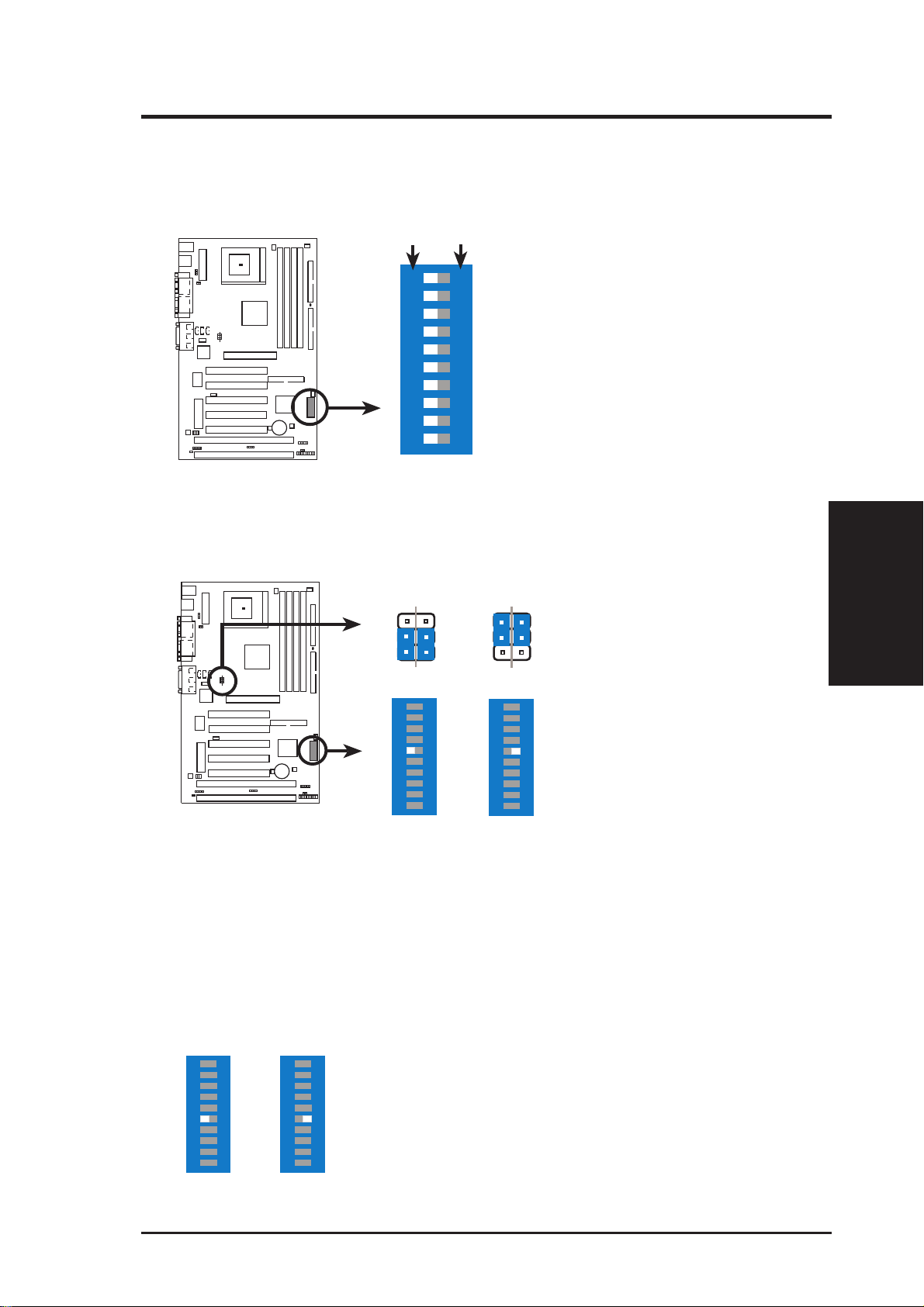
1. Keyboard Power Up (3-pin KBPWR)
This allows you to disable or enable the keyboard power up function. Set this
jumper to Enable if you wish to use your keyboard (by pressing the spacebar) to
power up your computer. This feature requires an ATX power supply that can
supply at least 300mA on the +5VSB lead. The default is set to Disable because
not all computers have the appropriate ATX power supply. Your computer will
not power on if you set this to Enable and if you do not have the right ATX
power supply.
KBPWR
3
2
1
Disable
(Default)
MEL Keyboard Power Up
KBPWR
3
2
1
Enable
14 ASUS MEL User’s Manual
III. HARDWARE SETUP
Motherboard Feature Settings (DIP Switches)
The motherboard’ s onboard features can be adjusted through the DIP switches. The
white block represents the switch’s position. The example below shows all the
switches in the OFF position.
OFF
ON
12345678910
ON
<Frequency Selector
<Frequency Selector
<Frequency Selector
<Reserved
<Onboard Audio Setting
<VIO Setting
<Frequency Multiple
<Frequency Multiple
<Frequency Multiple
<Frequency Multiple
MEL DIP Switches
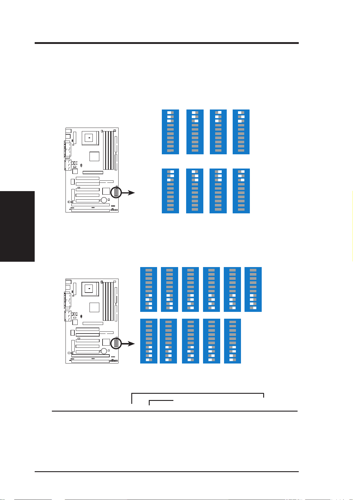
2. Onboard Audio Settings (DIP5, REQ5, GNT5)
The onboard audio can be turned ON or OFF using DIP5 in conjunction with the
REQ5 and GNT5 jumpers.
GNT5
REQ5
3
2
1
Disable
ON
12345 678910
REQ5
3
2
1
Enable
ON
12345 678910
GNT5
DIP Switches
III. H/W SETUP
MEL Audio Setting
NOTE: The onboard audio shares REQ5 and GNT5 with PCI slot 5. Therefore,
if the onboard audio is enabled, bus master cards cannot be used on PCI slot 5.
3. VIO Setting (DIP6)
The onboard voltage regulator allows you to select the voltage supplied to the
DRAM, chipset, AGP, and the CPU’s I/O buffer. IMPORTANT! Setting this
jumper to Add 0.1 Volt may cause your system to become unstable. It is strongly
recommended that you leave this jumper on its default setting of Normal (3.5V).
Normal Add 0.1Volt
ON
123456 78910
ON
123456 78910
MEL VIO Setting
ASUS MEL User’s Manual 15
III. HARDWARE SETUP
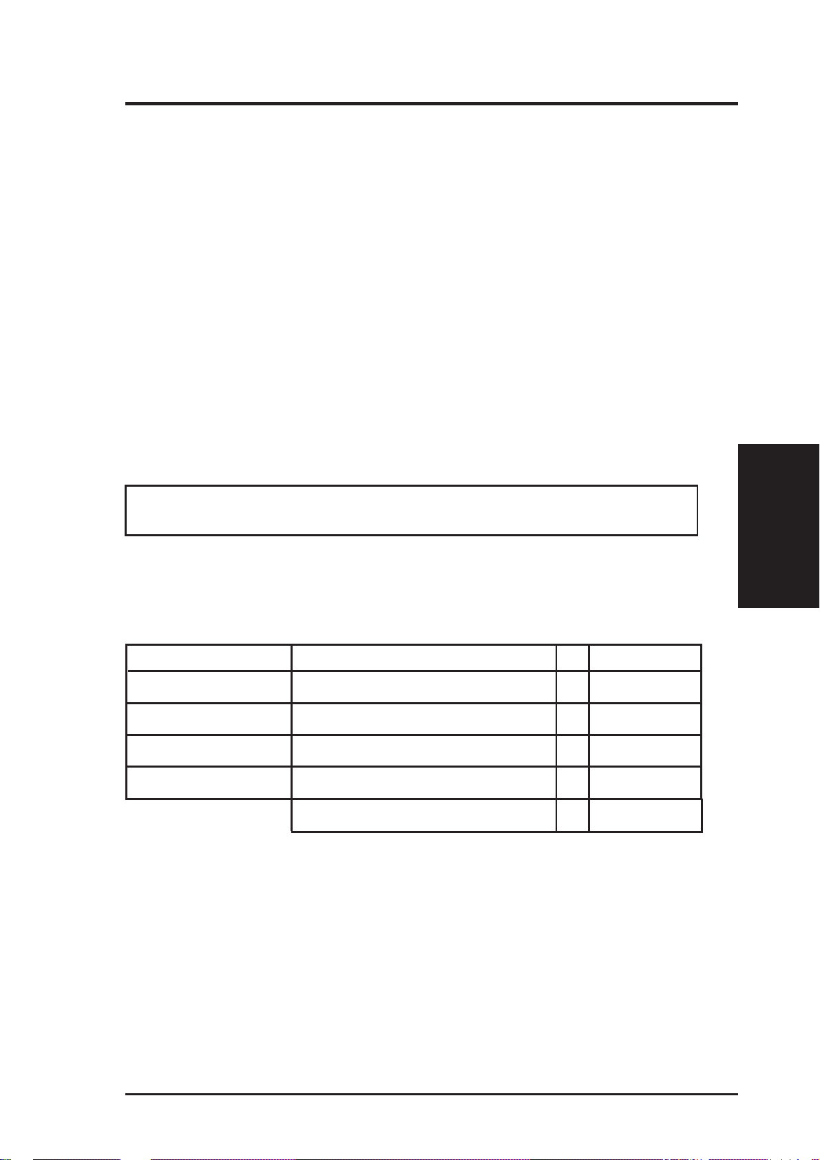
4. CPU External (BUS) Frequency Selection (DIP1, 2, 3)
These function switches tell the clock generator what frequency to send to the
CPU. These allow the selection of the CPU’ s External frequency (or BUS Clock).
The BUS Clock times the BUS Ratio equals the CPU's Internal frequency (the
advertised CPU speed).
III. H/W SETUP
Dip Switches
5. CPU to BUS Frequency Multiple (DIP7, 8, 9, 10)
CPU/AGP
PCI BUS
CPU/AGP
PCI BUS
→
→
→
→
66.8MHz
33.4MHz
ON
12345678910
78MHz
39MHz
ON
12345678910
68.5MHz
34.2MHz
ON
12345678910
80MHz
40MHz
ON
12345678910
72MHz
36MHz
ON
12345678910
81MHz
40.5MHz
ON
12345678910
75MHz
37.5MHz
ON
12345678910
83.3MHz
41.7MHz
ON
12345678910
MEL CPU BUS Frequency Selection
These function switches set the frequency multiple between the Internal frequency of the CPU and the External frequency (called the BUS Clock) within
the CPU.
ON
3.5x(7/2)
12345678910
3.0x(3/1) 5.5x(11/2)
12345678910
ON
4.0x(4/1)
12345678910
ON
4.5x(9/2)
12345678910
ON
5.0x(5/1)
12345678910
ON
ON
12345678910
6.0x(6/1)
ON
12345678910
6.5x(13/2)
ON
12345678910
7.0x(7/1)
ON
12345678910
7.5x(15/2)
12345678910
ON
8.0x(8/1)
12345678910
ON
MEL CPU : BUS Frequency Multiple
Set the function switches by the Internal speed of your processor as follows:
(BUS Frequency) (Frequency Multiple)
Intel CPU Model Speed Mult Freq. DIP1 DIP2 DIP3 DIP7 DIP8 DIP9 DIP10
Celeron (PPGA) 466MHz 7.0x 66MHz [OFF] [OFF] [OFF] [ON] [OFF] [ON] [OFF]
Celeron (PPGA) 433MHz 6.5x 66MHz [OFF] [OFF] [OFF] [OFF] [ON] [ON] [OFF]
Celeron (PPGA) 400MHz 6.0x 66MHz [OFF] [OFF] [OFF] [ON] [ON] [ON] [OFF]
Celeron (PPGA) 366MHz 5.5x 66MHz [OFF] [OFF] [OFF] [OFF] [OFF] [OFF] [ON]
Celeron (PPGA) 333MHz 5.0x 66MHz [OFF] [OFF] [OFF] [ON] [OFF] [OFF] [ON]
Celeron (PPGA) 300MHz 4.5x 66MHz [OFF] [OFF] [OFF] [OFF] [ON] [OFF] [ON]
16 ASUS MEL User’s Manual
III. HARDWARE SETUP
2. System Memory (DIMM)
NOTE: No hardware or BIOS setup is required after adding or removing memory.
This motherboard uses only Dual Inline Memory Modules (DIMMs). Sockets are
available for 3.3Volt (power level) unbuffered Synchronous Dynamic Random Ac-
cess Memory (SDRAM) of either 8, 16, 32, 64, 128MB, or 256MB. One side (with
memory chips) of the DIMM takes up one row on the motherboard.
To utilize the chipset’s Error Checking and Correction (ECC) feature, you must use a
DIMM module with 9 chips per side (standard 8 chips/side + 1 parity chip) and make
the proper settings in BIOS Chipset Features Setup of BIOS SETUP.
Memory speed setup is recommended through “SDRAM Configuration” under
Chipset Features Setup in BIOS SETUP.
NOTE: The LX chipset does not support registered DIMMs.
W ARNING! Memory modules must have 18 chips or less. Memory modules with
more than 18 chips exceed specifications and may cause unstable operation.
Install memory in any combination as follows:
DIMM Location 168-pin DIMM Total Memory
Socket 1 (Rows 0&1) SDRAM 8, 16, 32, 64, 128, 256MB x1
Socket 2 (Rows 2&3) SDRAM 8, 16, 32, 64, 128, 256MB x1
Socket 3 (Rows 4&5) SDRAM 8, 16, 32, 64, 128, 256MB x1
Socket 4 (Rows 6&7) SDRAM 8, 16, 32, 64, 128, 256MB x1
Total System Memory (Max 1024MB) =
General DIMM Notes
• Two possible memory chips are supported: SDRAM with and without ECC.
• SDRAM chips are generally thinner with higher pin density than EDO (Extended Data Output) chips.
• BIOS shows SDRAM memory on bootup screen.
• 8 chips/side modules do not support ECC, only 9 chips/side modules support ECC.
• Single-sided DIMMs come in 16, 32, 64,128MB; double-sided come in 32, 64,
128, 256MB.
III. H/W SETUP
System Memory
ASUS MEL User’s Manual 17
DIMM Memory Installation
Insert the module(s) as shown. Because the number of pins are different on either
side of the breaks, the module will only fit in the orientation as shown. DIMM
modules are longer and have different pin contact on each side and therefore have a
higher pin density. SIMM modules have the same pin contact on both sides.
System Memory
III. H/W SETUP
III. HARDWARE SETUP
Lock
FRONT
20 Pins 60 Pins 88 Pins
MEL 168-Pin DIMM Sockets
The DIMMs must be 3.3V Unbuffered for this motherboard. T o determine the DIMM
type, check the notches on the DIMMs (see figure below).
168-Pin DIMM Notch Key Definitions (3.3V)
DRAM Key Position
RFU
Buffered
Unbuffered
The notches on the DIMM module will shift between left, center, or right to identify
the type and also to prevent the wrong type from being inserted into the DIMM slot on
the motherboard. You must ask your retailer the correct DIMM type before purchasing. This motherboard supports four clock signals.
Voltage Key Position
5.0V
Reserved
3.3V
18 ASUS MEL User’s Manual
III. HARDWARE SETUP
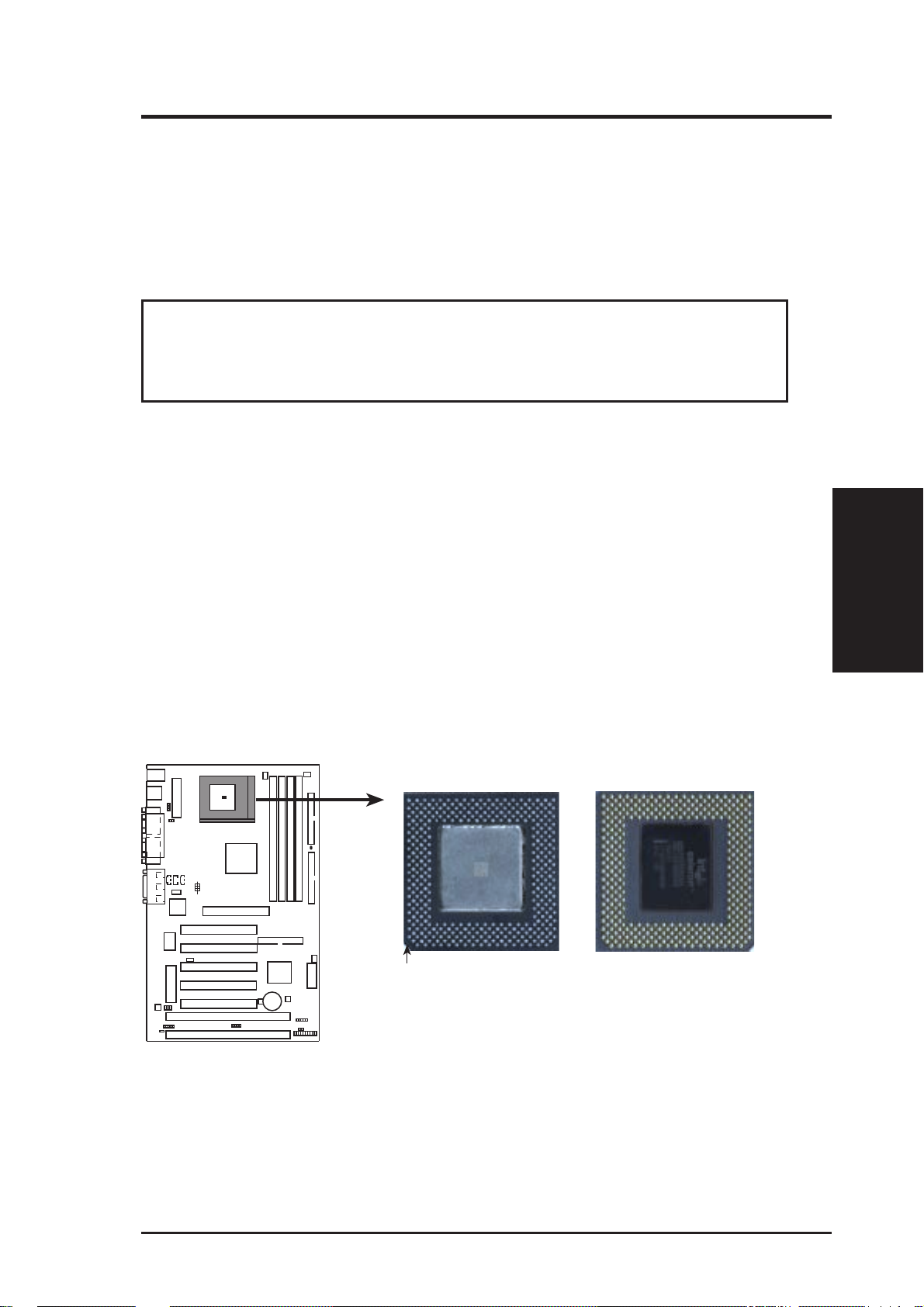
3. Central Processing Unit (CPU)
The motherboard provides a ZIF Socket 370. The CPU that came with the motherboard should have a fan attached to it to prevent overheating. If this is not the case
then purchase a fan before you turn on your system.
WARNING! Be sure that there is suf ficient air circulation across the processor’ s
heatsink by regularly checking that your CPU fan is working. W ithout suf ficient
circulation, the processor could overheat and damage both the processor and the
motherboard. You may install an auxiliary fan, if necessary.
To install a CPU, first turn off your system and remove its cover. Locate the ZIF
socket and open it by first pulling the lever sideways away from the socket then
upwards to a 90-degree right angle. Insert the CPU with the correct orientation as
shown. The notched corner should point towards the end the of the lever. Because
the CPU has a corner pin for two of the four corners, the CPU will only fit in the one
orientation as shown. The picture is for reference only; you should have a CPU fan
that will cover the face of the CPU. W ith the added weight of the CPU fan, no force
is required to insert the CPU. Once completely inserted, close the socket’s lever
while holding down the CPU.
CPU
III. H/W SETUP
NOTE: Set the bus frequency and multiple for your Socket 370 processor.
Socket 370 CPU (Top) Socket 370 CPU (Bottom)
Notch
MEL Socket 370
ASUS MEL User’s Manual 19

(This page was intentionally left blank.)
III. H/W SETUP
III. HARDWARE SETUP
CPU
20 ASUS MEL User’s Manual

III. HARDWARE SETUP
4. Expansion Cards
WARNING! Make sure that you unplug your power supply when adding or
removing expansion cards or other system components. Failure to do so may
cause severe damage to both your motherboard and expansion cards.
Expansion Card Installation Procedure
1. Read the documentation for your expansion card and make any necessary hardware or software settings for your expansion card, such as jumpers.
2. Remove your computer system’s cover and the bracket plate on the slot you
intend to use. Keep the bracket for possible future use.
3. Carefully align the card’s connectors and press firmly.
4. Secure the card on the slot with the screw you removed above.
5. Replace the computer system’s cover.
6. Set up the BIOS if necessary
(such as IRQ xx Used By ISA: Yes in PNP AND PCI SETUP)
7. Install the necessary software drivers for your expansion card.
Assigning IRQs for Expansion Cards
Some expansion cards need to use an IRQ to operate. Generally, an IRQ must be
exclusively assigned to one use. In a standard design, there are 16 IRQs available
but most of them are already in use, leaving 6 IRQs free for expansion cards. If your
motherboard has PCI audio onboard, 1 extra IRQ will be used, leaving 5 IRQs free.
If your motherboard has ISA audio onboard, an extra 3 IRQs will be used, leaving 3
IRQs free.
NOTE: Your onboard audio shares an IRQ with PCI slots 4 and 5.
Both ISA and PCI expansion cards may require to use IRQs. System IRQs are avail-
able to cards installed in the ISA expansion bus first, then any remaining IRQs are
available to PCI cards. Currently , there are two types of ISA cards. The original ISA
expansion card design, now referred to as legacy ISA cards, requires that you configure the card’ s jumpers manually and then install it in any available slot on the ISA
bus. You may use the Microsoft Diagnostics (MSD.EXE) utility located in the W indows directory to see a map of your used and free IRQs. If you use W indows 95, the
Resources tab under Device Manager displays the resource settings being used by
a particular device (to gain access, double-click the System icon under the Control
Panel program). Ensure that no two devices share the same IRQs or your computer
will experience problems when those two devices are in use at the same time.
III. H/W SETUP
Expansion Cards
ASUS MEL User’s Manual 21
T o simplify this process this motherboard has complied with the Plug and Play (PNP)
specification which was developed to allow automatic system configuration whenever a PNP-compliant card is added to the system. For PNP cards, IRQs are assigned automatically from those available.
If the system has both Legacy and PNP ISA cards installed, IRQs are
assigned to PNP cards from those not used by Legacy cards. The PCI and PNP
configuration of the BIOS setup utility can be used to indicate which IRQs are being
used by Legacy cards. For older Legacy cards that does not work with the BIOS,
you can contact your vendor for an ISA Configuration Utility.
An IRQ number is automatically assigned to PCI expansion cards after those used
by Legacy and PNP ISA cards. In the PCI bus design, the BIOS automatically
assigns an IRQ to a PCI slot that has a card in it that requires an IRQ. To install a
PCI card, you need to set something called the INT (interrupt) assignment. Since all
the PCI slots on this motherboard use an INTA #, be sure that the jumpers on your
PCI cards are set to INT A.
Expansion Cards
III. H/W SETUP
Assigning DMA Channels for ISA Cards
Some ISA cards, both legacy and PnP, may also need to use a DMA (Direct Memory
Access) channel. DMA assignments for this motherboard are handled the same way
as the IRQ assignment process described earlier. You can select a DMA channel in
the PCI and PnP configuration section of the BIOS Setup utility.
III. HARDWARE SETUP
NOTE: The onboard audio by default uses DMA1.
IMPORTANT: To avoid conflicts, reserve the necessary IRQs and DMAs for legacy
ISA cards (under PNP AND PCI SETUP of BIOS SETUP, choose Yes in IRQ xx Used
By ISA and DMA x Used By ISA for those IRQs and DMAs you want to reserve).
ISA Cards and Hardware Monitor
The onboard hardware monitor uses the address 290H-297H so legacy ISA cards
must not use this address or else conflicts will occur.
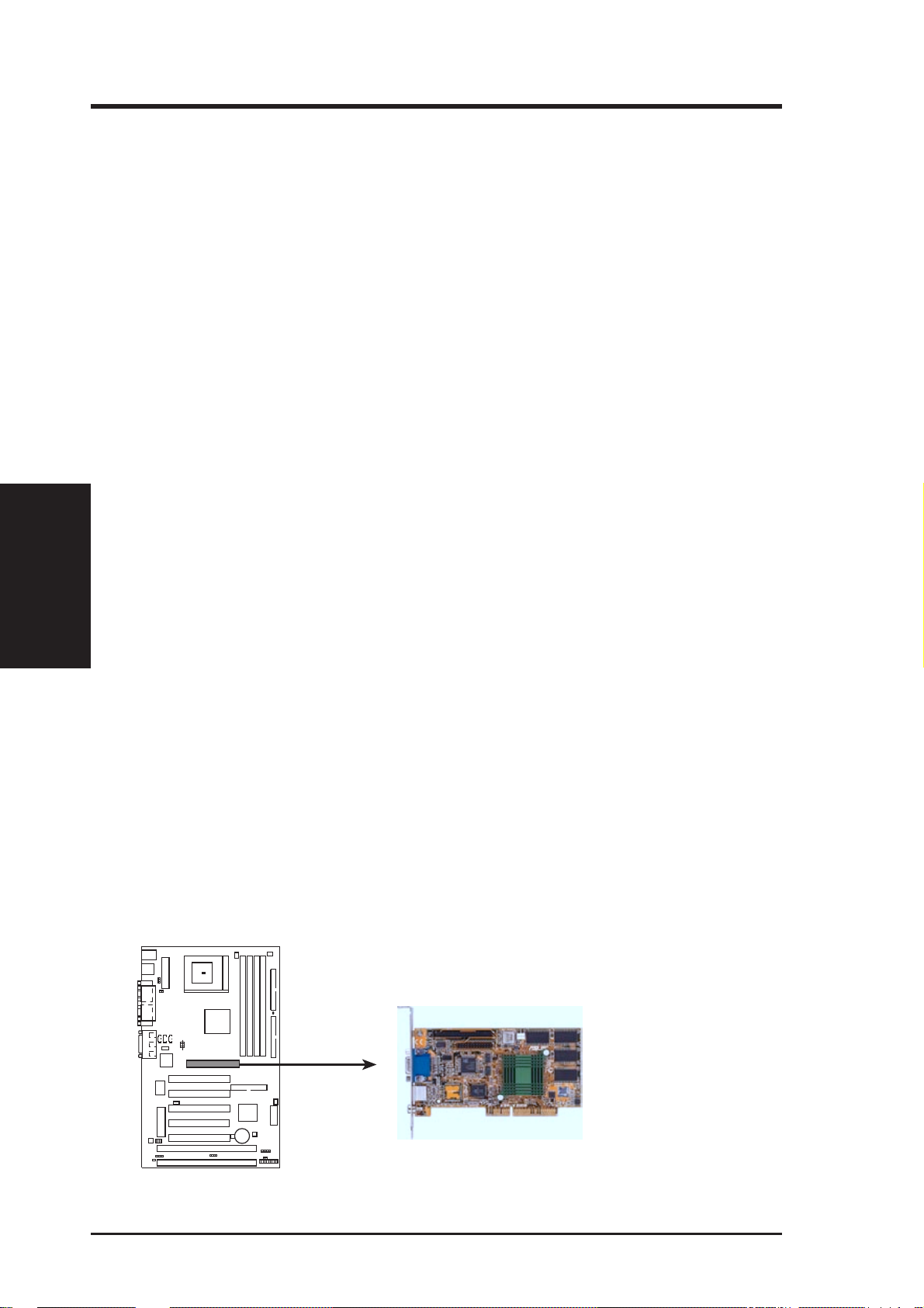
Accelerated Graphics Port
This motherboard provides an accelerated graphics port (AGP) slot to support a new
generation of graphics cards with ultra-high memory bandwidth, such as an ASUS
3D hardware accelerator.
MEL Accelerated Graphics Port (AGP)
22 ASUS MEL User’s Manual
III. HARDWARE SETUP
5. External Connectors
WARNING! Some pins are used for connectors or power sources. These are
clearly distinguished from jumpers in the Motherboard Layout. Placing jumper
caps over these connector pins will cause damage to your motherboard.
IMPORTANT: Ribbon cables should always be connected with the red stripe on the
Pin 1 side of the connector. The four corners of the connectors are labeled on the
motherboard. Pin 1 is the side closest to the power connector on hard drives and
floppy drives. IDE ribbon cable must be less than 46 cm(18 in.), with the second drive
connector no more than 15 cm (6 in.) from the first connector.
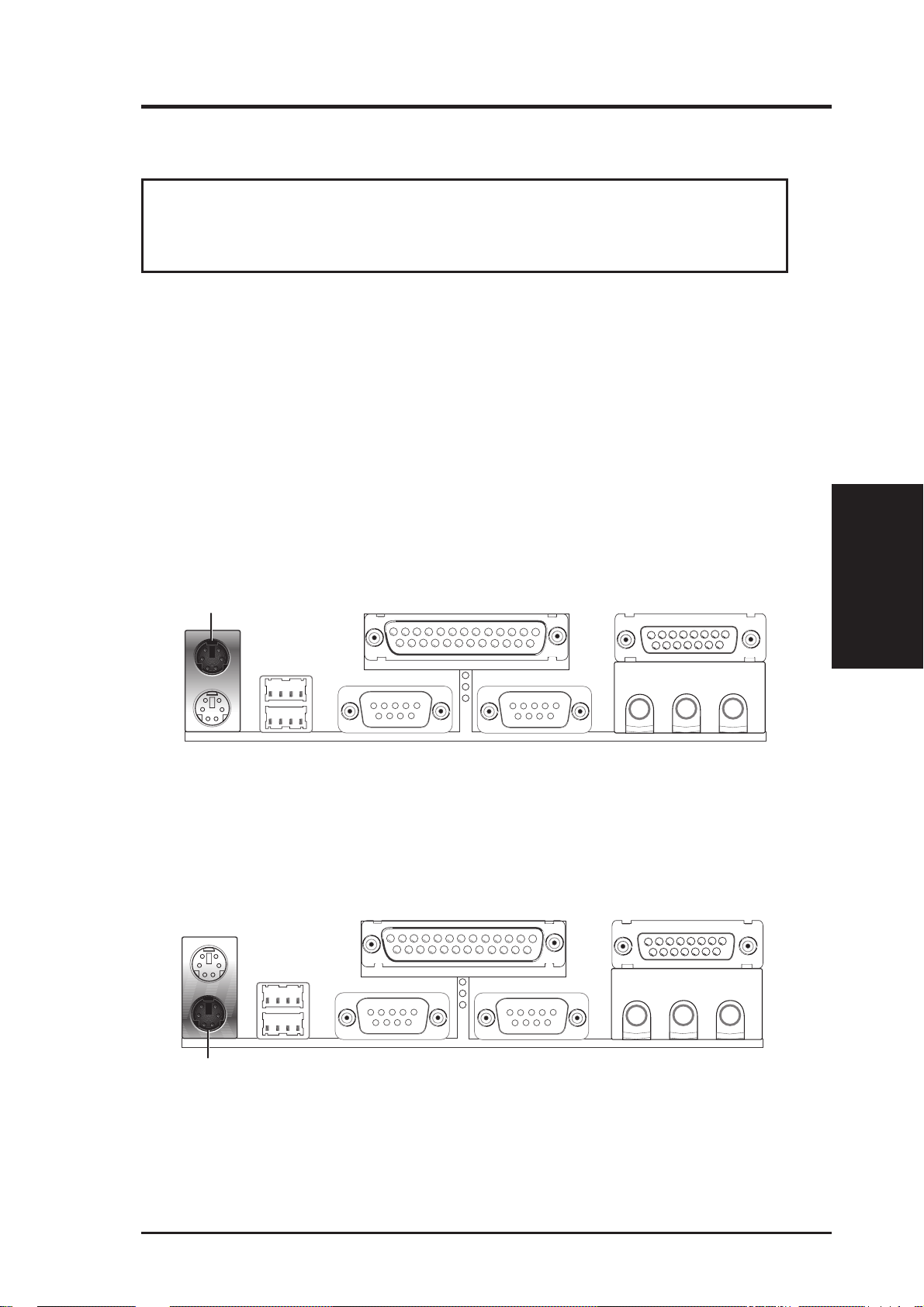
1. PS/2 Mouse Connector (6-pin PS2KBMS)
The system will direct IRQ12 to the PS/2 mouse if one is detected. If not detected, expansion cards can use IRQ12. See “PS/2 Mouse Control” in BIOS
Features Setup of the BIOS SETUP.
PS/2 Mouse (6-pin Female)
2. PS/2 Keyboard Connector (6-pin PS2KBMS)
This connection is for a standard keyboard using an PS/2 plug (mini DIN). This
connector will not allow standard AT size (large DIN) keyboard plugs. You
may use a DIN to mini DIN adapter on standard AT keyboards.
Connectors
DMA Channels
III. H/W SETUP
III. H/W SETUP
PS/2 Keyboard (6-pin Female)
ASUS MEL User’s Manual 23
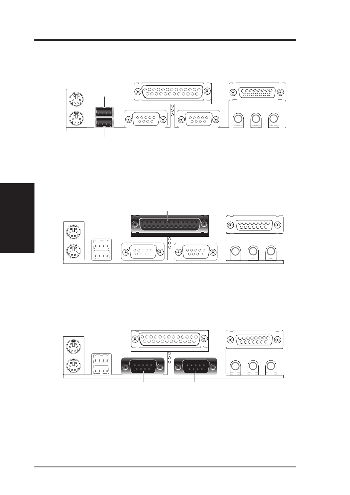
3. Universal Serial BUS Ports 1 & 2 (Two 4-pin USB)
4. Parallel Port Connector (25-pin PRINTER)
III. H/W SETUP
Connectors
III. HARDWARE SETUP
Two USB ports are available for connecting USB devices.
USB 1
Universal Serial Bus (USB) 2
You can enable the parallel port and choose the IRQ through “Onboard Parallel
Port” in Chipset Features Setup of BIOS SETUP.
NOTE: Serial printers must be connected to the serial port.
Parallel (Printer) Port (25-pin Female)
5. Serial Port Connectors (Two 9-pin COM1/COM2)
The two serial ports can be used for pointing devices or other serial devices. See
“Onboard Serial Port” in Chipset Features Setup of BIOS SETUP.
COM 1 COM 2
Serial Ports (9-pin Male)
24 ASUS MEL User’s Manual
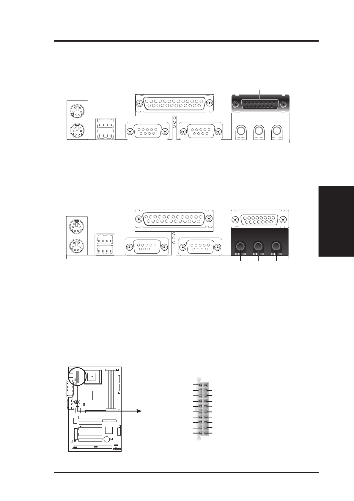
III. HARDWARE SETUP
6. Joystick/Midi Connector (optional) (15-pin GAME_AUDIO)
You may connect game joysticks or game pads to this connector for playing
games. Connect MIDI devices for playing or editing audio.
Joystick/Midi (15-pin Female)
7. Audio Port Connectors (optional) (Three 1/8” GAME_AUDIO)
Line Out can be connected to headphones or preferably powered speakers.
Line In allows tape players or other audio sources to be recorded by your com-
puter or played through the Line Out. Mic allows microphones to be connected
for inputing voice.
MicLine InLine Out
1/8" Stereo Audio Connectors
8. ATX Power Supply Connector (20-pin block ATXPWR)
This connector connects to an ATX power supply . The plug from the power supply will only insert in one orientation because of the different hole sizes. Find the
proper orientation and push down firmly making sure that the pins are aligned.
IMPORTANT: Make sure that your ATX power supply can supply at least 10mA
on the +5-volt standby lead (+5VSB). You may experience difficulty in powering on your system if your power supply cannot support the load. For Wake-OnLAN support, your ATX power supply must supply at least 720mA +5VSB.
+3.3Volts
-12.0Volts
Ground
Power Supply On
Ground
Ground
Ground
-5.0 Volts
+5.0 Volts
+5.0 Volts
+3.3 Volts
+3.3 Volts
Ground
+5.0 Volts
Ground
+5.0 Volts
Ground
Power Good
+5V Standby
+12.0Volts
Connectors
III. H/W SETUP
MEL ATX Power Connector
ASUS MEL User’s Manual 25
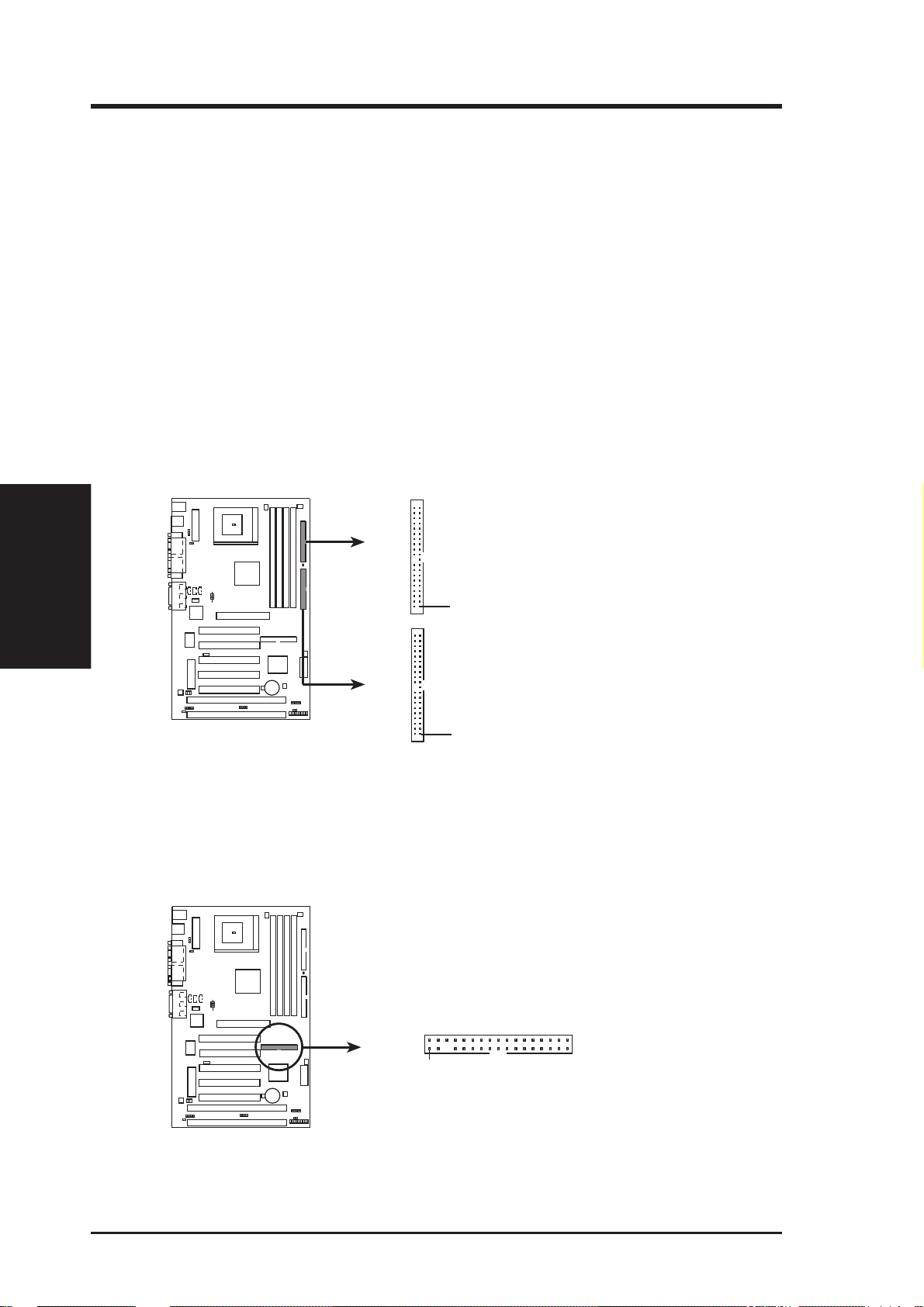
9. Primary / Secondary IDE connectors (Two 40-1pin IDE)
III. H/W SETUP
Connectors
III. HARDWARE SETUP
These connectors support the provided IDE hard disk ribbon cable.
After connecting the single end to the board, connect the two plugs at the other
end to your hard disk(s). If you install two hard disks, you must configure the
second drive to Slave mode by setting its jumper accordingly . Please refer to the
documentation of your hard disk for the jumper settings. BIOS now supports
SCSI device or IDE CD-ROM bootup (see “HDD Sequence SCSI/IDE First” &
“Boot Sequence” in BIOS Features Setup of BIOS SETUP) (Pin 20 is removed
to prevent inserting in the wrong orientation when using ribbon cables with
pin 20 plugged).
TIP: You may configure two hard disks to be both Masters using one ribbon
cable on the primary IDE connector and another ribbon cable on the secondary
IDE connector. You may install one operating system on an IDE drive and another on a SCSI drive and select the boot disk through BIOS Features Setup.
Secondary IDE Connector
MEL IDE Connectors
PIN 1
Primary IDE Connector
PIN 1
NOTE: Orient the red markings
(usually zigzag) on the IDE
ribbon cable to
PIN 1
10. Floppy Disk Drive Connector (34-1pin FLOPPY)
This connector supports the provided floppy drive ribbon cable. After connecting the single end to the board, connect the two plugs on the other end to the
floppy drives. (Pin 5 is removed to prevent inserting in the wrong orienta-
tion when using ribbon cables with pin 5 plugged).
NOTE: Orient the red markings on
the floppy ribbon cable to PIN 1
PIN 1
MEL Floppy Disk Drive Connector
26 ASUS MEL User’s Manual
III. HARDWARE SETUP
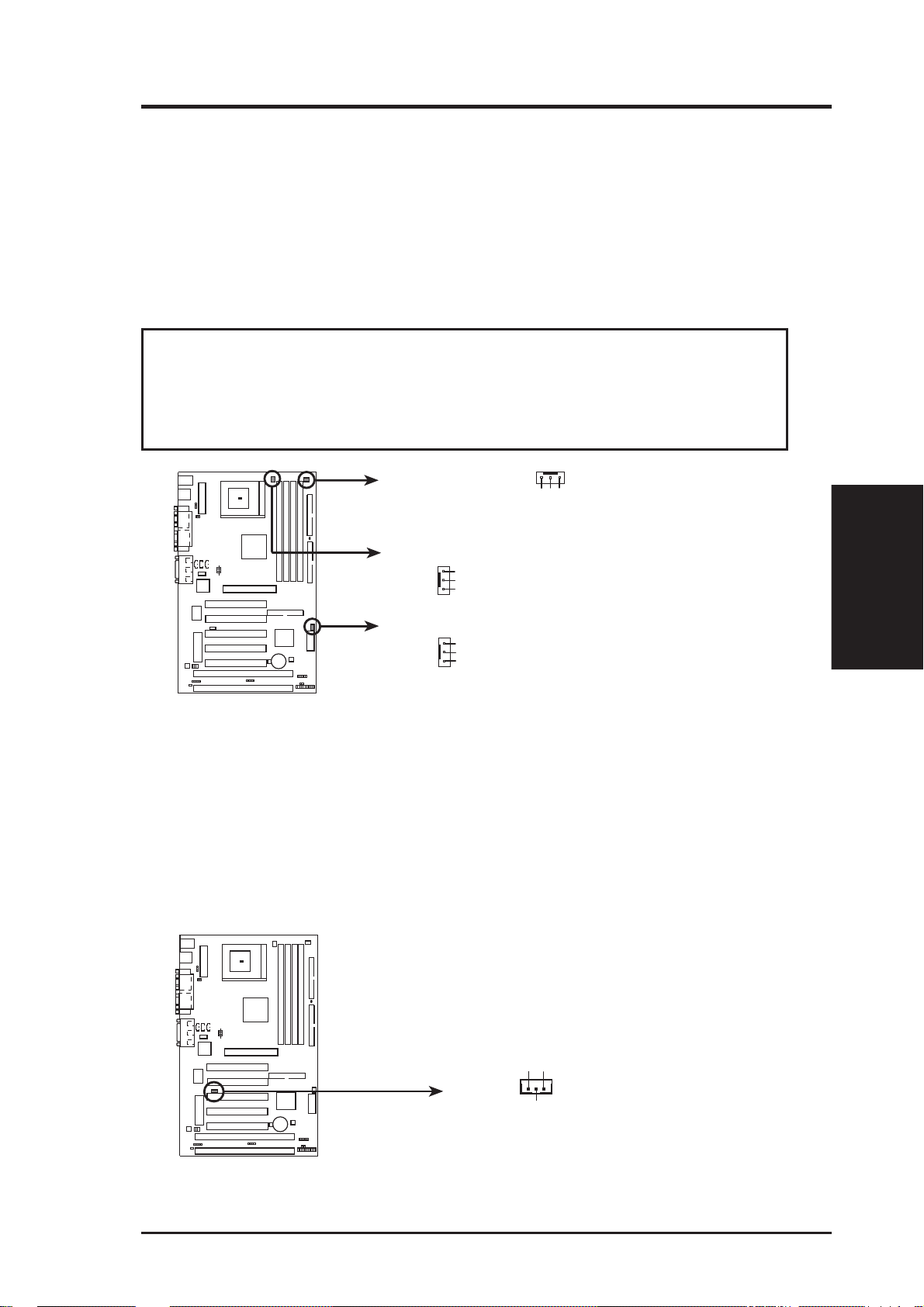
11. Chassis, CPU , & Power Supply Fan Connectors (3-pin CHA_, CPU_, PWR_F AN)
These connectors support cooling fans of 500mA (6 Watts) or less. Orientate
the fans so that the heat sink fins allow airflow to go across the onboard heat
sink(s) instead of the expansion slots. Depending on the fan manufacturer, the
wiring and plug may be different. The red wire should be positive, while the
black should be ground. Connect the fan’ s plug to the board taking into consideration the polarity of the this connector . NOTE: The “Rotation” signal is to
be used only by a specially designed fan with rotation signal.
WARNING! The CPU and/or motherboard will overheat if there is no airflow
across the CPU and onboard heatsinks. Damage may occur to the motherboard
and/or the CPU fan if these pins are incorrectly used. These are not jumpers,
do not place jumper caps over these pins.
Power Supply Fan
GND
+12V
Rotation
CPU Fan Power
GND
+12V
Rotation
Chassis Fan Power
GND
+12V
Rotation
MEL 12-Volt Cooling Fan Power Connector
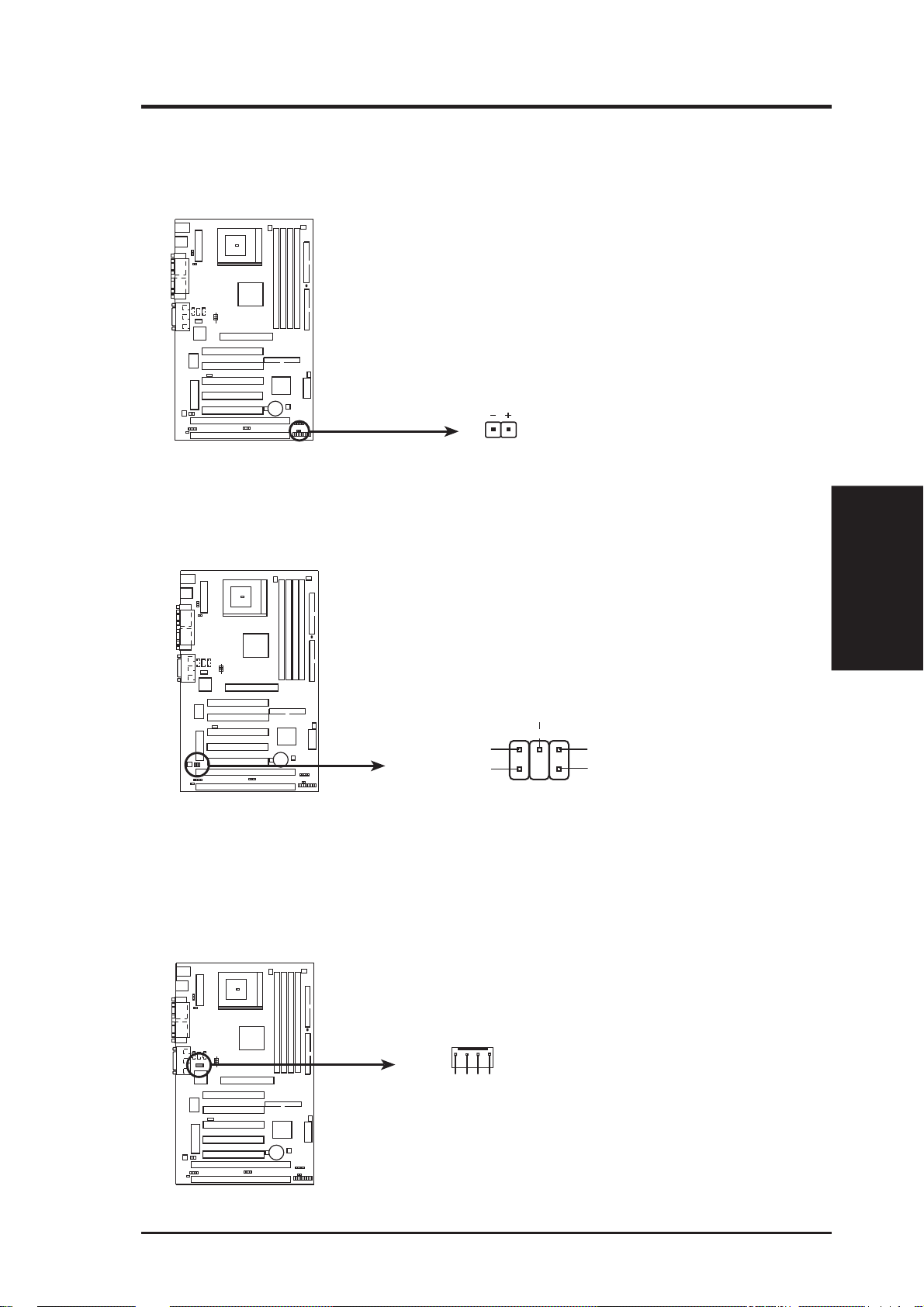
12. Wake-On-LAN Connector (3-pin WOL_CON)
These connector connects to LAN cards with a W ake-On-LAN output, such as the
ASUS PCI-L101. The connector powers up the system when a wakeup packet or
signal is received through the LAN card.
IMPORTANT: This feature requires that the WAKE On LAN Power Up Control is
set to Enabled (see Power Management Setup under BIOS SETUP) and that your
system has an ATX power supply with at least 720mA +5V standby power.
Connectors
III. H/W SETUP
MEL Wake-On-LAN Connector
ASUS MEL User’s Manual 27
+5 Volt Standby
Ground
IMPORTANT: Requires an ATX power
supply with at least 720mA +5-volt
standby power
PME
13. Wake-On-Ring Connector (2-pin WOR)
III. H/W SETUP
Connectors
III. HARDWARE SETUP
This connector connects to internal modem cards with a Wake-On-Ring output.
The connector powers up the system when a ringup packet or signal is received
through the internal modem card. NOTE: For external modems, W ake-On-Ring
is detected through the COM port.
IMPORTANT: This feature requires that the PWR UP On Modem Act Power Up
Control is set to Enabled (see Power Management Setup under BIOS SETUP) and that
your system has an ATX power supply with at least 720mA +5V standby power .
WOR
Pin 2 PIXRI#
Pin 1 Ground
MEL Wake-On-Ring Connector
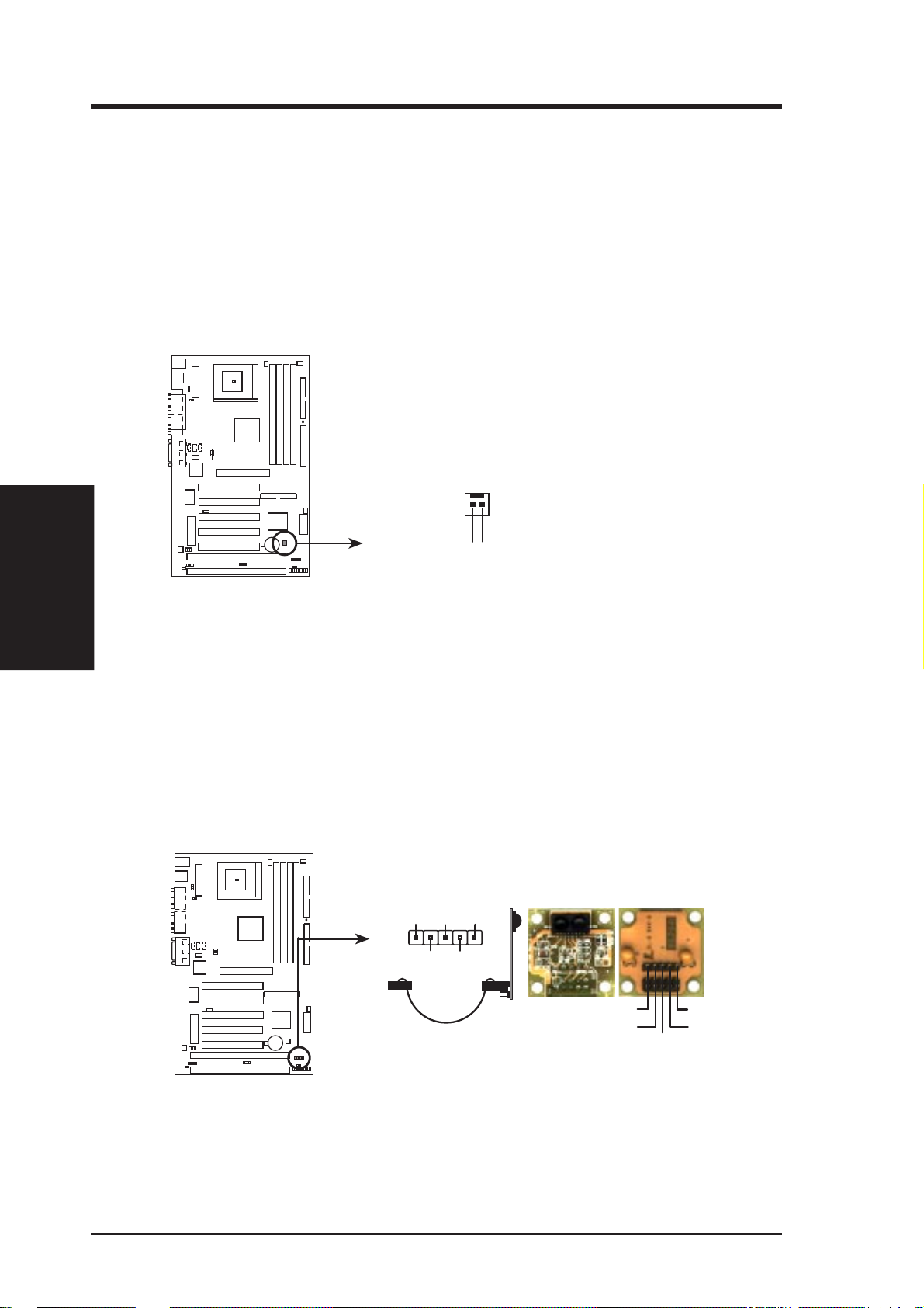
14. IrDA-Compliant Infrared Module Connector (5-pin IR)
This connector supports the optional wireless transmitting and receiving infrared
module. This module mounts to a small opening on system cases that support this
feature. You must also configure the setting through “UART2 Use Infrared” in
Chipset Features Setup to select whether UART2 is directed for use with COM2
or IrDA. Use the five pins as shown on the Back V iew and connect a ribbon cable
from the module to the motherboard according to the pin definitions.
+5V IRRX IRTX
Front View
(NC) GND
Back View
IRTX
GND
IRRX
+5V
(NC)
MEL Infrared Module Connector
28 ASUS MEL User’s Manual
III. HARDWARE SETUP
15. IDE Device Activity LED (2-pin IDELED)
This connector supplies power to the cabinet’s hard disk or IDE activity LED.
Read and write activity by devices connected to the Primary or Secondary IDE
connectors will cause the LED to light up.
TIP: If the case-mounted LED does not
light, try reversing the 2-pin plug.
IDELED
MEL IDE Activity LED
16. SB-Link™ Connector (6-1 pin SBLINK)
If you have a Sound Blaster compatible PCI audio card, you must link it to this
connector . Otherwise, you will have compatibility issues under DOS environment.
NOTE: Pin 3 is removed to ensure the
correct orientation of the cable on it.
PC/PCI Request
Sideband Signal
2
4
6
DGND
PC/PCI Grant
Sideband Signal
1
Serial IRQ
DGND
5
MEL SB-Link™ Connector
17. Voice Modem In Connector (optional) (4-pin MODEM)
This connector allows the onboard audio to interface with a voice modem card.
It also allows the sharing of microphone and speaker between the onboard audio
and the voice modem card. NOTE: Your voice modem card requires a similar
connector to use this feature.
MODEM
Connectors
III. H/W SETUP
Ground
Modem-In
MEL Modem Card Voice In Connector
ASUS MEL User’s Manual 29
Ground
Modem-Out
 Loading...