

Page 1

KGN(M)H-D16 Series
KGNH-D16
KGMH-D16/QDR
Motherboard
Page 2

E6105
Second Edition
October 2010
Copyright © 2010 ASUSTeK COMPUTER INC. All Rights Reserved.
No part of this manual, including the products and software described in it, may be reproduced, transmitted,
transcribed, stored in a retrieval system, or translated into any language in any form or by any means,
except documentation kept by the purchaser for backup purposes, without the express written permission
of ASUSTeK COMPUTER INC. (“ASUS”).
Product warranty or service will not be extended if: (1) the product is repaired, modied or altered, unless
such repair, modication of alteration is authorized in writing by ASUS; or (2) the serial number of the
product is defaced or missing.
ASUS PROVIDES THIS MANUAL “AS IS” WITHOUT WARRANTY OF ANY KIND, EITHER EXPRESS
OR IMPLIED, INCLUDING BUT NOT LIMITED TO THE IMPLIED WARRANTIES OR CONDITIONS OF
MERCHANTABILITY OR FITNESS FOR A PARTICULAR PURPOSE. IN NO EVENT SHALL ASUS, ITS
DIRECTORS, OFFICERS, EMPLOYEES OR AGENTS BE LIABLE FOR ANY INDIRECT, SPECIAL,
INCIDENTAL, OR CONSEQUENTIAL DAMAGES (INCLUDING DAMAGES FOR LOSS OF PROFITS,
LOSS OF BUSINESS, LOSS OF USE OR DATA, INTERRUPTION OF BUSINESS AND THE LIKE),
EVEN IF ASUS HAS BEEN ADVISED OF THE POSSIBILITY OF SUCH DAMAGES ARISING FROM ANY
DEFECT OR ERROR IN THIS MANUAL OR PRODUCT.
SPECIFICATIONS AND INFORMATION CONTAINED IN THIS MANUAL ARE FURNISHED FOR
INFORMATIONAL USE ONLY, AND ARE SUBJECT TO CHANGE AT ANY TIME WITHOUT NOTICE, AND
SHOULD NOT BE CONSTRUED AS A COMMITMENT BY ASUS. ASUS ASSUMES NO RESPONSIBILITY
OR LIABILITY FOR ANY ERRORS OR INACCURACIES THAT MAY APPEAR IN THIS MANUAL,
INCLUDING THE PRODUCTS AND SOFTWARE DESCRIBED IN IT.
Products and corporate names appearing in this manual may or may not be registered trademarks or
copyrights of their respective companies, and are used only for identication or explanation and to the
owners’ benet, without intent to infringe.
ii
Page 3

Contents
Notices ........................................................................................................ vii
Safety information .................................................................................... viii
About this guide ......................................................................................... ix
Typography .................................................................................................. x
KGN(M)H-D16 Series specications summary ........................................ xi
Chapter 1: Product introduction
1.1 Welcome! ...................................................................................... 1-3
1.2 Package contents ......................................................................... 1-3
1.3 Serial number label ...................................................................... 1-4
1.4 Special features ............................................................................ 1-4
1.4.1 Product highlights ........................................................... 1-4
Chapter 2: Hardware information
2.1 Before you proceed ..................................................................... 2-3
2.2 Motherboard overview ................................................................. 2-5
2.2.1 Placement direction ........................................................ 2-5
2.2.2 Screw holes .................................................................... 2-5
2.2.3 Motherboard layouts ....................................................... 2-6
2.2.4 Layout contents ............................................................... 2-8
2.3 Central Processing Unit (CPU) ................................................. 2-10
2.3.1 Installing the CPU ......................................................... 2-10
2.3.2 Installing the CPU heatsink ........................................... 2-13
2.4 System memory ......................................................................... 2-14
2.4.1 Overview ....................................................................... 2-14
2.4.2 Memory Congurations ................................................. 2-15
2.4.3 Installing a DIMM .......................................................... 2-17
2.4.4 Removing a DIMM ........................................................ 2-17
2.5 Expansion slot ............................................................................ 2-18
2.5.1 Installing an expansion card ......................................... 2-18
2.5.2 Conguring an expansion card ..................................... 2-18
2.5.3 Interrupt assignments ................................................... 2-19
2.5.4 PCI Express x16 slot (x16 link) ..................................... 2-19
2.5.5 Installing ASMB4 management board ........................... 2-20
2.6 Jumpers ...................................................................................... 2-21
2.7 Connectors ................................................................................. 2-26
iii
Page 4

Contents
2.7.1 Rear panel connectors .................................................. 2-26
2.7.2 Internal connectors ....................................................... 2-27
Chapter 3: Powering up
3.1 Starting up for the rst time ........................................................ 3-3
3.2 Powering off the computer .......................................................... 3-4
3.2.1 Using the OS shut down function .................................... 3-4
3.2.2 Using the dual function power switch .............................. 3-4
Chapter 4: BIOS setup
4.1 Managing and updating your BIOS ............................................ 4-3
4.1.1 ASUS EZ Flash 2 utility ................................................... 4-3
4.1.2 BUPDATER utility............................................................ 4-4
4.1.3 ASUS CrashFree BIOS 3 utility ...................................... 4-6
4.2 BIOS setup program .................................................................... 4-7
4.2.1 BIOS menu screen .......................................................... 4-8
4.2.2 Menu bar ......................................................................... 4-8
4.2.3 Navigation keys ............................................................... 4-8
4.2.4 Menu items ..................................................................... 4-9
4.2.5 Sub-menu items .............................................................. 4-9
4.2.6 Conguration elds ......................................................... 4-9
4.2.7 Pop-up window ............................................................... 4-9
4.2.8 Scroll bar ......................................................................... 4-9
4.2.9 General help ................................................................... 4-9
4.3 Main menu .................................................................................. 4-10
4.3.1 System Time ................................................................. 4-10
4.3.2 System Date ................................................................. 4-10
4.3.3 SATA1—6 ...................................................................... 4-10
4.3.4 Storage Conguration ................................................... 4-12
4.3.5 System Information ....................................................... 4-13
4.4 Advanced menu ......................................................................... 4-15
4.4.1 CPU Conguration ........................................................ 4-15
4.4.2 Chipset Conguration ................................................... 4-17
4.4.3 Onboard Devices Conguration .................................... 4-24
4.4.4 USB Conguration ........................................................ 4-25
4.4.5 PCIPnP ......................................................................... 4-26
iv
Page 5

Contents
4.5 Server menu ............................................................................... 4-27
4.5.1 Remote Access Conguration ....................................... 4-27
4.6 Power menu ................................................................................ 4-29
4.6.1 ACPI APIC Support ....................................................... 4-29
4.6.2 APM Conguration ........................................................ 4-29
4.6.3 Hardware Monitor ......................................................... 4-30
4.7 Boot menu .................................................................................. 4-32
4.7.1 Boot Device Priority ...................................................... 4-32
4.7.2 Hard Disk Drives; CDROM Drives ................................ 4-32
4.7.3 Boot Settings Conguration .......................................... 4-33
4.7.4 Security ......................................................................... 4-34
4.8 Tools menu ................................................................................. 4-36
4.8.1 ASUS EZ Flash 2 .......................................................... 4-36
4.9 Exit menu .................................................................................... 4-37
Chapter 5: RAID conguration
5.1 Setting up RAID ............................................................................ 5-3
5.1.1 RAID denitions .............................................................. 5-3
5.1.2 Installing hard disk drives ................................................ 5-4
5.1.3 Setting the RAID item in BIOS ........................................ 5-4
5.2 FastBuild Utility ............................................................................ 5-5
5.2.1 Creating a RAID set ........................................................ 5-6
5.2.2 Deleting a RAID set ...................................................... 5-12
5.2.3 Viewing the Drive Assignment....................................... 5-14
5.2.4 Viewing the Controller Conguration............................. 5-15
Chapter 6: Driver installation
6.1 RAID driver installation ............................................................... 6-3
6.1.1 Creating a RAID driver disk ............................................ 6-3
6.1.2 Installing the RAID controller driver ................................ 6-5
6.2 ATI SM Bus controller driver installation ................................. 6-15
6.3 LAN driver installation ............................................................... 6-16
6.4 Display driver installation ......................................................... 6-20
6.5 Mellanox ConnectX QDR PCI Gen2 Channel Adapter driver
installation (For KGMH-D16/QDR only) .................................... 6-23
6.5.1 Windows operating system ........................................... 6-23
v
Page 6

Contents
6.5.2 Red Hat® Enterprise Linux OS ...................................... 6-27
6.6 Management applications and utilities installation ................ 6-30
6.6.1 Running the support DVD ............................................. 6-30
6.6.2 Drivers menu ................................................................. 6-30
6.6.3 Utilities menu ................................................................ 6-31
6.6.4 Make disk menu ............................................................ 6-31
6.6.5 Contact information ....................................................... 6-31
Appendix: Reference information
A.1 KGNH-D16 block diagram ...........................................................A-3
A.2 KGMH-D16/QDR block diagram ..................................................A-4
vi
Page 7

Notices
Federal Communications Commission Statement
This device complies with Part 15 of the FCC Rules. Operation is subject to the
following two conditions:
•
This device may not cause harmful interference, and
•
This device must accept any interference received including interference that
may cause undesired operation.
This equipment has been tested and found to comply with the limits for a
Class B digital device, pursuant to Part 15 of the FCC Rules. These limits are
designed to provide reasonable protection against harmful interference in a
residential installation. This equipment generates, uses and can radiate radio
frequency energy and, if not installed and used in accordance with manufacturer’
s instructions, may cause harmful interference to radio communications. However,
there is no guarantee that interference will not occur in a particular installation. If
this equipment does cause harmful interference to radio or television reception,
which can be determined by turning the equipment off and on, the user is
encouraged to try to correct the interference by one or more of the following
measures:
•
Reorient or relocate the receiving antenna.
•
Increase the separation between the equipment and receiver.
•
Connect the equipment to an outlet on a circuit different from that to which the
receiver is connected.
•
Consult the dealer or an experienced radio/TV technician for help.
The use of shielded cables for connection of the monitor to the graphics card is
required to assure compliance with FCC regulations. Changes or modications
to this unit not expressly approved by the party responsible for compliance could
void the user’s authority to operate this equipment.
Canadian Department of Communications Statement
This digital apparatus does not exceed the Class B limits for radio noise emissions
from digital apparatus set out in the Radio Interference Regulations of the
Canadian Department of Communications.
This class B digital apparatus complies with Canadian ICES-003.
REACH
Complying with the REACH (Registration, Evaluation, Authorization, and Restriction
of Chemicals) regulatory framework, we published the chemical substances in our
products at ASUS REACH website at http://green.asus.com/english/REACH.htm.
vii
Page 8

Safety information
Electrical safety
• To prevent electrical shock hazard, disconnect the power cable from the
electrical outlet before relocating the system.
• When adding or removing devices to or from the system, ensure that the
power cables for the devices are unplugged before the signal cables are
connected. If possible, disconnect all power cables from the existing system
before you add a device.
• Before connecting or removing signal cables from the motherboard, ensure
that all power cables are unplugged.
• Seek professional assistance before using an adapter or extension cord.
These devices could interrupt the grounding circuit.
• Make sure that your power supply is set to the correct voltage in your area.
If you are not sure about the voltage of the electrical outlet you are using,
contact your local power company.
• If the power supply is broken, do not try to x it by yourself. Contact a
qualied service technician or your retailer.
Operation safety
• Before installing the motherboard and adding devices on it, carefully read all
the manuals that came with the package.
• Before using the product, make sure all cables are correctly connected and the
power cables are not damaged. If you detect any damage, contact your dealer
immediately.
• To avoid short circuits, keep paper clips, screws, and staples away from
connectors, slots, sockets and circuitry.
• Avoid dust, humidity, and temperature extremes. Do not place the product in
any area where it may become wet.
• Place the product on a stable surface.
• If you encounter technical problems with the product, contact a qualied
service technician or your retailer.
viii
This symbol of the crossed out wheeled bin indicates that the product (electrical,
electronic equipment, and mercury-containing button cell battery) should not
be placed in municipal waste. Check local regulations for disposal of electronic
products.
Page 9

About this guide
This user guide contains the information you need when installing and conguring
the motherboard.
How this guide is organized
This user guide contains the following parts:
• Chapter 1: Product introduction
This chapter describes the features of the motherboard and the new
technologies it supports.
• Chapter 2: Hardware information
This chapter lists the hardware setup procedures that you have to perform
when installing system components. It includes description of the switches,
jumpers, and connectors on the motherboard.
• Chapter 3: Powering up
This chapter describes the power up sequence and ways of shutting down
the system.
• Chapter 4: BIOS setup
This chapter tells how to change system settings through the BIOS Setup
menus. Detailed descriptions of the BIOS parameters are also provided.
• Chapter 5: Driver installation
This chapter provides instructions for installing the necessary drivers for
different system components.
• Appendix: Reference information
This appendix includes additional information that you may refer to when
conguring the motherboard.
Where to nd more information
Refer to the following sources for additional information and for product and
software updates.
1. ASUS websites
The ASUS website provides updated information on ASUS hardware and
software products. Refer to the ASUS contact information.
2. Optional documentation
Your product package may include optional documentation, such as warranty
yers, that may have been added by your dealer. These documents are not
part of the standard package.
ix
Page 10

Conventions used in this guide
To make sure that you perform certain tasks properly, take note of the following
symbols used throughout this manual.
DANGER/WARNING:
when trying to complete a task.
CAUTION:
when trying to complete a task.
IMPORTANT:
task.
NOTE:
task.
Information to prevent damage to the components
Instructions that you MUST follow to complete a
Tips and additional information to help you complete a
Information to prevent injury to yourself
Typography
Bold text
Italics
<Key> Keys enclosed in the less-than and greater than sign means that you must press the
enclosed key.
Example: <Enter> means that you must press
the Enter or Return key.
<Key1+Key2+Key3> If you must press two or more keys
simultaneously, the key names are linked with
a plus sign (+).
Indicates a menu or an item to select.
Used to emphasize a word or a phrase.
Example: <Ctrl+Alt+Del>
Command
exactly as shown, then supply the required
item or value enclosed in brackets.
Example: At the DOS prompt, type the
command line:
x
Means that you must type the command
format A:/S
Page 11
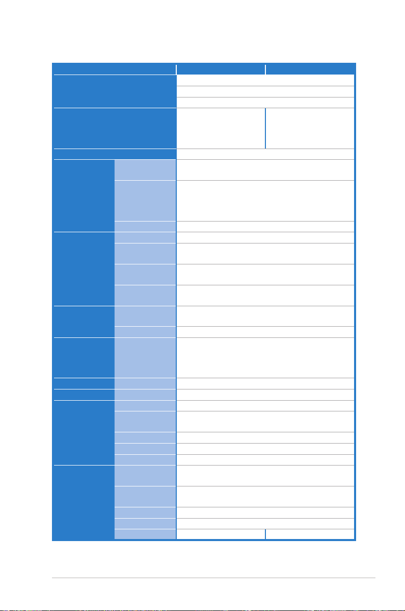
KGN(M)H-D16 Series specications summary
Model Name KGNH-D16 KGMH-D16/QDR
Processor Support / System Bus
Core Logic
Form Factor
ASUS Features Fan Speed
Memory Total Slots
Expansion Slots
(follow SSI
Loacation #)
Storage SATA Controller
Networking LAN
Graphic VGA
Onboard I/O
Connectors
Rear I/O
Connectors
Control
Rack Ready
(Rack and
Pedestal dual
use)
ASWM 2.0
Capacity
Memory Type
Memory Size
Total PCI/PCI-X/
PCI-E Slots
Slot Loacation 1
PSU Connector
Management
connector
USB Connectors
Fan Header
SMBus
External Serial
Port
External USB
Port
VGA Port
RJ-45
Inniband
2*socket G34 (LGA1944)
8/12 Core AMD Opteron™ 6100 series
6.4 GT/s per link (dual link)
- AMD SR5650
- AMD SP5100
Half SSI. 6.8" x 16.7"
V
V
V
16 (4-channel per CPU)
Maximum up to 256GB (RDIMM)
Maximum up to 64GB (UDIMM)
DDR3 800/1066/1333 UDIMM with ECC/non ECC
DDR3 800/1066/1333 RDIMM
1GB, 2GB, 4GB, 8GB, 16GB (RDIMM)
1GB, 2GB, 4GB (UDIMM)
1
1*PCI-E x16 (Gen2 X16 Link)
- AMD SP5100
- 6 x SATA2 300MB/s ports
- PROMISE® RAID (for Linux/Windows, supports
RAID 0,1, 10, 5)
2 * Intel 82574L + 1 * Mgmt LAN
Aspeed AST2050 8MB
20-pin x 2
Onboard socket for optional management card
2 (One for internal Type A USB connector)
4 * 4-pin
2
1
2
1
2 + 1 Management Port
- AMD SR5670
- AMD SP5100
- Mellanox ConnectX-2
MT25418 B0 QDR
1
xi
Page 12
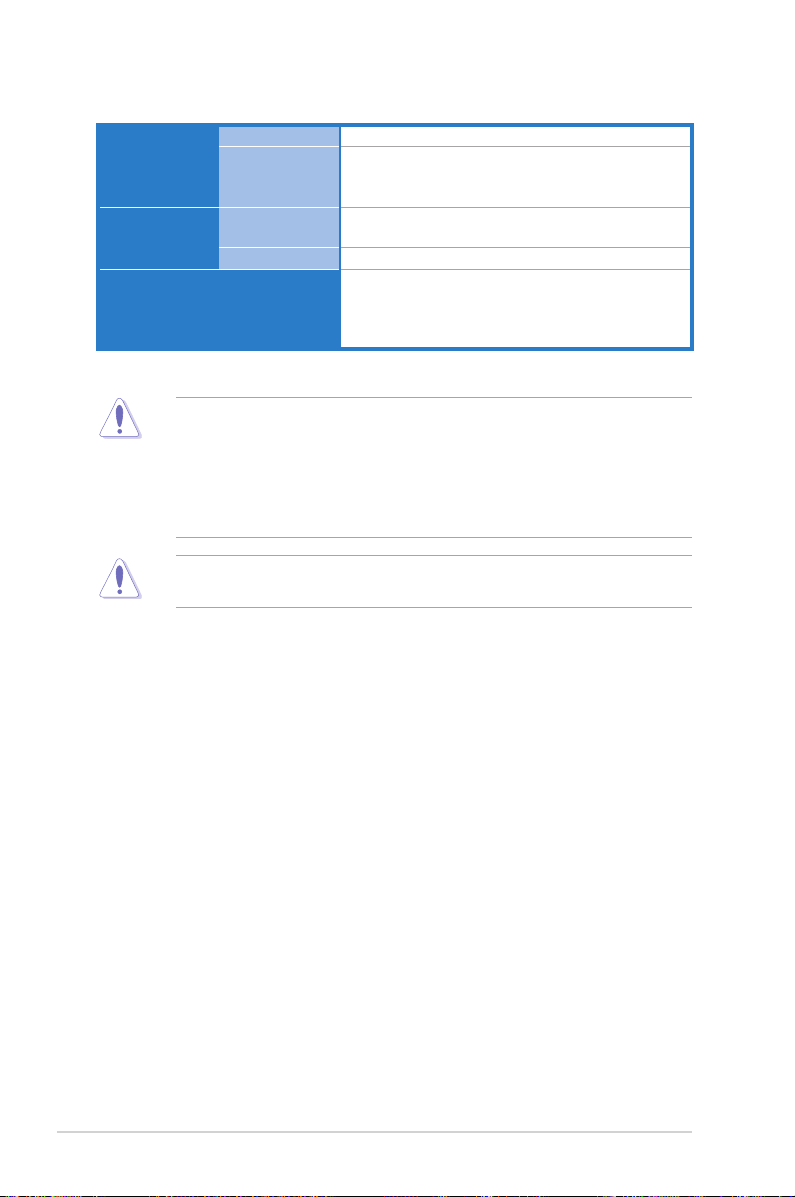
KGN(M)H-D16 Series specications summary
Management
Solution
Monitoring CPU
Environment
Specications are subject to change without notice.
Software
Out of Band
Remote
Management
Temperature
FAN RPM
• The 20-pin proprietory power connectors are not compatible with SSI power
supply. USE THE PROPRIETARY POWER SUPPLY ONLY; otherwise you
may damage the motherboard.
• The 4-pin EZ_PLUG is designed for hard disk drives power supply. DO
NOT connect other 4-pin power connectors of the power supply unit (PSU)
to this connector.
DO NOT touch the Northbridge chipset! The Northbridge chipset may become
overheated. Remember to provide sufcient air ow to keep the system stable.
ASWM
Optional ASMB4-iKVM for KVM-over-Internet
V
V
Operation temperature: 10°C—35°C
Non operation temperature: -40°C—70°C
Non operation humidity: 20%—90% (non condensing)
xii
Page 13

This chapter describes the motherboard
features and the new technologies it supports.
Product
introduction
1
Page 14

Chapter summary
1
1.1 Welcome! ...................................................................................... 1-3
1.2 Package contents ......................................................................... 1-3
1.3 Serial number label ...................................................................... 1-4
1.4 Special features ............................................................................ 1-4
ASUS KGN(M)H-D16
Page 15
1.1 Welcome!
Thank you for buying an ASUS® KGN(M)H-D16 motherboard!
The motherboard delivers a host of new features and latest technologies, making it
another standout in the long line of ASUS quality motherboards!
Before you start installing the motherboard, and hardware devices on it, check the
items in your package with the list below.
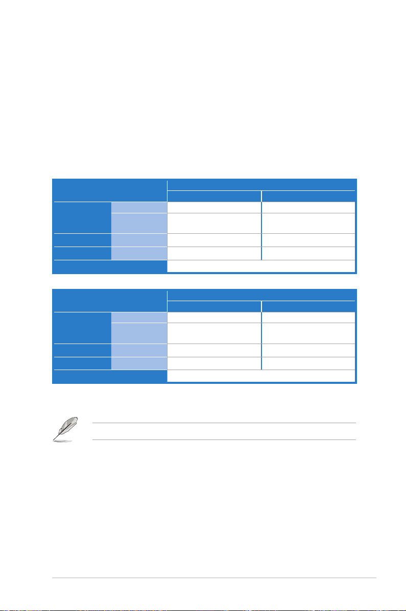
1.2 Package contents
Check your motherboard package for the following items.
Standard Bulk Pack
KGNH-D16 KGMH-D16/QDR
Support DVD
Application CD
Documentation User Guide
Cable Thermistor
Packing Qty.
Application CD
Documentation User Guide
Cable Thermistor
Packing Qty.
Mellanox
SDVD*
Support DVD
Mellanox
SDVD*
1 1
1
1 1
2 2
10pcs per carton
Standard Gift Box Pack
KGNH-D16 KGMH-D16/QDR
1 1
1
1 1
2 2
1pcs per carton
* The Mellanox driver is included in the motherboard support DVD or in an individual driver disc,
depending on the shipping sequence. This is subjected to change without notice.
If any of the above items is damaged or missing, contact your retailer.
ASUS KGN(M)H-D16 1-3
Page 16

1.3 Serial number label
Before requesting support from the ASUS Technical Support team, you must take
note of the motherboard's serial number containing 13 characters
shown as the gure below. With the correct serial number of the product, ASUS
Technical Support team members can then offer a quicker and satisfying solution
to your problems.
xxS2xxxxxxxxx
KGN(M)H-D16
xxS2xxxxxxxxx
Made
in
China
合格
1.4 Special features
1.4.1 Product highlights
Latest processor technology
This motherboard supports the latest AMD® Opteron™ 6100 series processors
in LGA 1944 package with integrated memory controller to support 4-channel (8
DIMM per CPU) DDR3 memory. AMD® Opteron™ 6100 series processor supports
AMD® HyperTransport™ technology with a system bus of up to 6.4GT/s per link.
AMD® Opteron™ 6100 series processor is the one of the most powerful and
energy-efcient CPUs in the world.
AMD 8/12 Core architecture
The motherboard supports AMD 8/12 core processors with discrete L2 cache
structure for each core and shared L3 cache to meet demands for more powerful
computing.
HyperTransport™ technology 3.0 (HT3)
HyperTransport™ technology 3.0 (HT3) is a high-speed, low latency, point-topoint link designed to improve the overall system balance and scalability with the
maximum interconnect rate of 6.4GT/s.
1-4 Chapter 1: Product introduction
Page 17

DDR3 memory support
The KGN(M)H-D16 supports UDIMM and RDIMM DDR3 memory that features
data transfer rates of 1333/1066 MHZ to meet the higher bandwidth requirements
of server and workstation applications. The 4-channel DDR3 architecture boosts
system performance, eliminating bottlenecks with peak bandwidth of up to 32GB/s.
Furthermore, the supply voltage for the memory is reduced form 1.8 V for DDR2
to just 1.5V, 1.35V, and 1.2V for DDR3. This voltage reduction limits the power
consumption and heat generation of DDR3 which makes it an ideal memory
solution.
PCIe 2.0
This motherboard supports the latest PCIe 2.0 device for twice the current speed
and bandwidth. This enhances system performance while still providing backward
compatibility to PCIe 1.0 devices.
82574L LAN solution
The motherboard comes with dual Gigabit LAN controllers and ports which provide
a total solution for your networking needs. The onboard Intel 82574L Gigabit LAN
controllers use the PCI Express interface and could achieve network throughput
close to Gigabit bandwidth.
Serial ATA II technology
The motherboard supports the Serial ATA II 3 Gb/s technology through the
Serial ATA interface and AMD SP5100 chipset. The Serial ATA II specication
provides twice the bandwidth of the current Serial ATA products with a host of new
features, including Native Command Queuing (NCQ), Power Management (PM)
Implementation Algorithm, and Hot Swap. Serial ATA allows thinner, more exible
cables with lower pin count and reduced voltage requirements.
USB 2.0 technology
The motherboard implements the Universal Serial Bus (USB) 2.0 specication,
dramatically increasing the connection speed from the 12 Mbps bandwidth on USB
1.1 to a fast 480 Mbps on USB 2.0. USB 2.0 is backward compatible with USB 1.1.
Temperature, fan, and voltage monitoring
The CPU temperature is monitored to prevent overheating and damage. The
system fan rotations per minute (RPM) is monitored for timely failure detection.
The chip monitors the voltage levels to ensure stable supply of current for critical
components.
ASUS KGN(M)H-D16 1-5
Page 18

100% solid, long life conductive polymer capacitors
This motherboard uses all high-quality conductive polymer capacitors for durability,
improved lifespan, and enhanced thermal capacity.
1-6 Chapter 1: Product introduction
Page 19

This chapter lists the hardware setup
procedures that you have to perform
when installing system components. It
includes description of the jumpers and
connectors on the motherboard.
Hardware
information
2
Page 20

Chapter summary
2
2.1 Before you proceed ..................................................................... 2-3
2.2 Motherboard overview ................................................................. 2-5
2.3 Central Processing Unit (CPU) ................................................. 2-10
2.4 System memory ......................................................................... 2-14
2.5 Expansion slot ............................................................................ 2-18
2.6 Jumpers ...................................................................................... 2-21
2.7 Connectors ................................................................................. 2-26
ASUS KGN(M)H-D16
Page 21
2.1 Before you proceed
Take note of the following precautions before you install motherboard components or change
any motherboard settings.
• Unplug the power cord from the wall socket before touching any
component.
• Use a grounded wrist strap or touch a safely grounded object or a metal
object, such as the power supply case, before handling components to
avoid damaging them due to static electricity.
• Hold components by the edges to avoid touching the ICs on them.
• Whenever you uninstall any component, place it on a grounded antistatic
pad or in the bag that came with the component.
• Before you install or remove any component, ensure that the power supply
is switched off or the power cord is detached from the power supply. Failure
to do so may cause severe damage to the motherboard, peripherals, and/or
components.
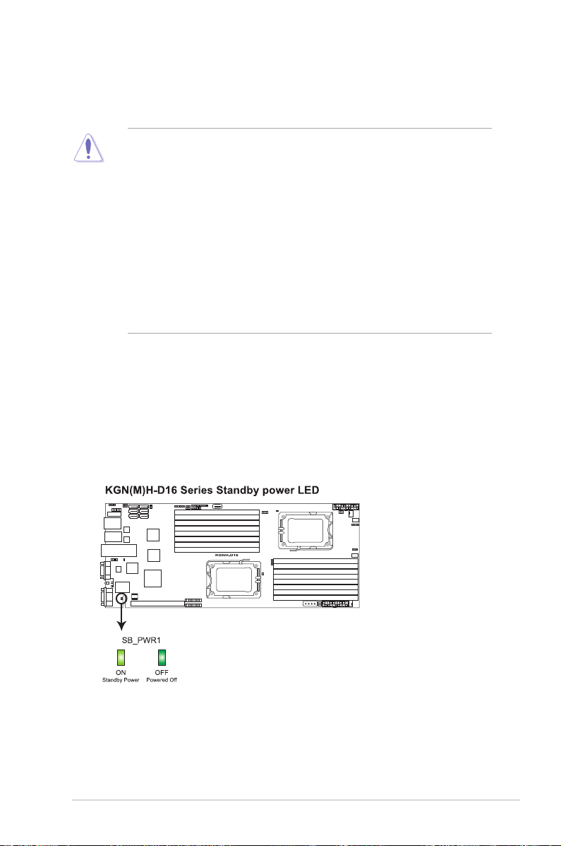
Onboard LED
1. Standby Power LED
The motherboard comes with a standby power LED. The green LED lights up
to indicate that the system is ON, in sleep mode, or in soft-off mode. This is a
reminder that you should shut down the system and unplug the power cable
before removing or plugging in any motherboard component. The illustration
below shows the location of the onboard LED.
ASUS KGN(M)H-D16 2-3
Page 22
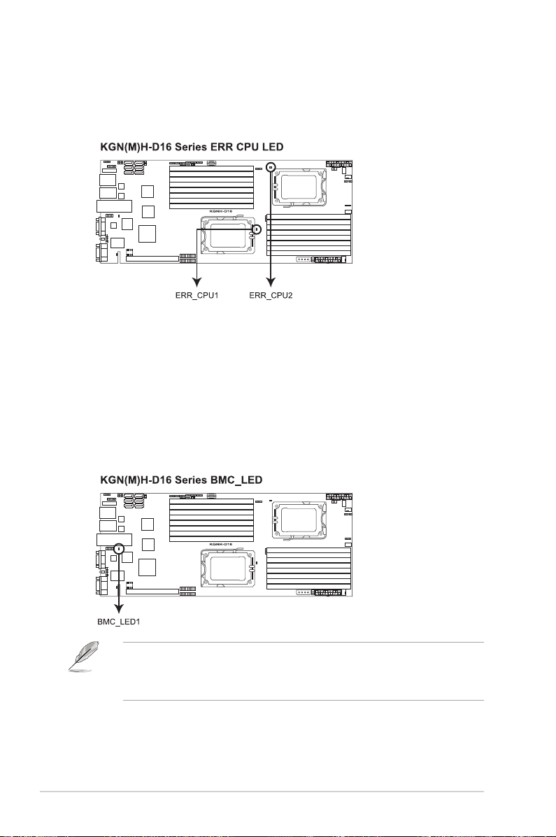
2. CPU warning LED (ERR_CPU1, ERR_CPU2)
The CPU warning LEDs light up to indicate that an impending failure of the
corresponding CPU.
3. BMC LED (BMC_LED1)
The green heartbeat LED blinks per second to indicate that the ASMB4 is
working normally.
• The heartbeat LED functions only when you install the ASUS ASMB4.
• Everytime after the AC power is replugged, you have to wait for about 30
seconds for the system power up
2-4 Chapter 2: Hardware information
Page 23
2.2 Motherboard overview
Before you install the motherboard, study the conguration of your chassis to
ensure that the motherboard ts into it.
To optimize the motherboard features, we highly recommend that you install it in an
SSI EEB 1.1 compliant chassis.
Ensure to unplug the chassis power cord before installing or removing the
motherboard. Failure to do so can cause you physical injury and damage
motherboard components!
2.2.1 Placement direction
When installing the motherboard, ensure that you place it into the chassis in the
correct orientation. The edge with external ports goes to the rear part of the chassis
as indicated in the image below.
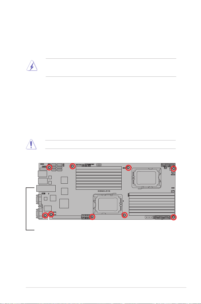
2.2.2 Screw holes
Place nine (9) screws into the holes indicated by circles to secure the motherboard
to the chassis.
DO NOT overtighten the screws! Doing so can damage the motherboard.
Place this side towards
the rear of the chassis
ASUS KGN(M)H-D16 2-5
Page 24
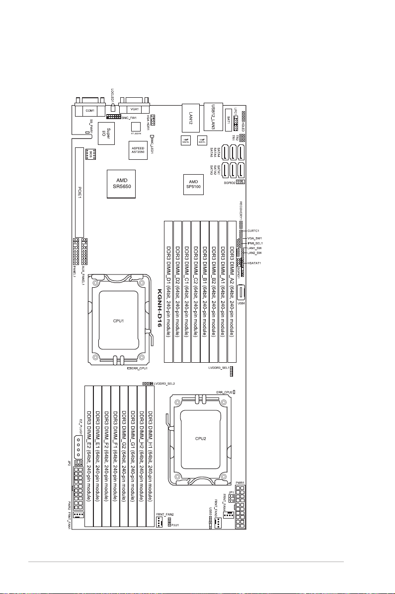
2.2.3 Motherboard layouts
KGNH-D16
2-6 Chapter 2: Hardware information
Page 25
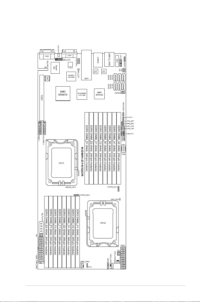
KGMH-D16/QDR
ASUS KGN(M)H-D16 2-7
Page 26
2.2.4 Layout contents
Slots/Soocket Page
1. CPU sockets 2-10
2. DDR3 sockets 2-14
3. PCI Express x 16 slot 2-19
Jumpers Page
1. Clear RTC RAM (CLRTC1)
2. VGA controller setting (3-pin VGA_SW1)
3. DDR3 voltage control setting
(4-pin LVDDR3_SEL1; LVDDR3_SEL2)
4. LAN controller setting (3-pin LAN_SW1, LAN_SW2)
5. Chassis intrusion connector (2-pin CHASSIS)
6. Force BIOS recovery setting (3-pin RECOVERY1)
7. IPMI setting (3-pin IPMI_SEL1)
Rear panel connectors Page
1. RJ-45 port for iKVM 2-26
2. LAN 2 (RJ-45) port 2-26
3. USB 2.0 ports 1 and 2 2-26
4. LAN 1 (RJ-45) port 2-26
5. InniBand (QSFP) 2-26
6. Video Graphics Adapter port 2-26
7. Location LED 2-26
8. Serial (COM1) port 2-26
2-21
2-22
2-22
2-23
2-23
2-24
2-25
2-8 Chapter 2: Hardware information
Page 27

Internal connectors Page
1. Serial ATA connectors
(7-pin SATA1, SATA2, SATA3, SATA4, SATA5, SATA6)
2. USB connectors (5-1 pin USB3, A-Type USB4)
3. Thermal sensor cable connectors (3-pin TR1, TR2)
4. Front fan connectors
(4-pin FRNT_FAN1, FRNT_FAN2, FRNT_FAN3, FRNT_FAN4)
5. LPC debug card connector (14-1 pin LPC1)
6. Serial General Purpose Input/Output connector (8-1 pin SGPIO1,
SGPIO2)
7. BMC header (BMC_FW1)
8. Power Supply SMBus connectors (6-1 pin JP1; JP2)
9. Proprietary power connectors
(20-pin PWR1, 20-pin PWR2, 4-pin PWR3)
10. HDD status indicator header (9-1 pin HSATAT1)
11. Hard disk activity LED connector (4-pin HDLED1)
12. Internal VGA Header (10-1 pin VGA_HDR1)
13. Auxiliary panel connector (20-pin AUX_PANEL1)
14. System panel connector (20-pin PANEL1)
2-27
2-28
2-28
2-29
2-30
2-30
2-31
2-31
2-32
2-33
2-33
2-34
2-35
2-36
ASUS KGN(M)H-D16 2-9
Page 28
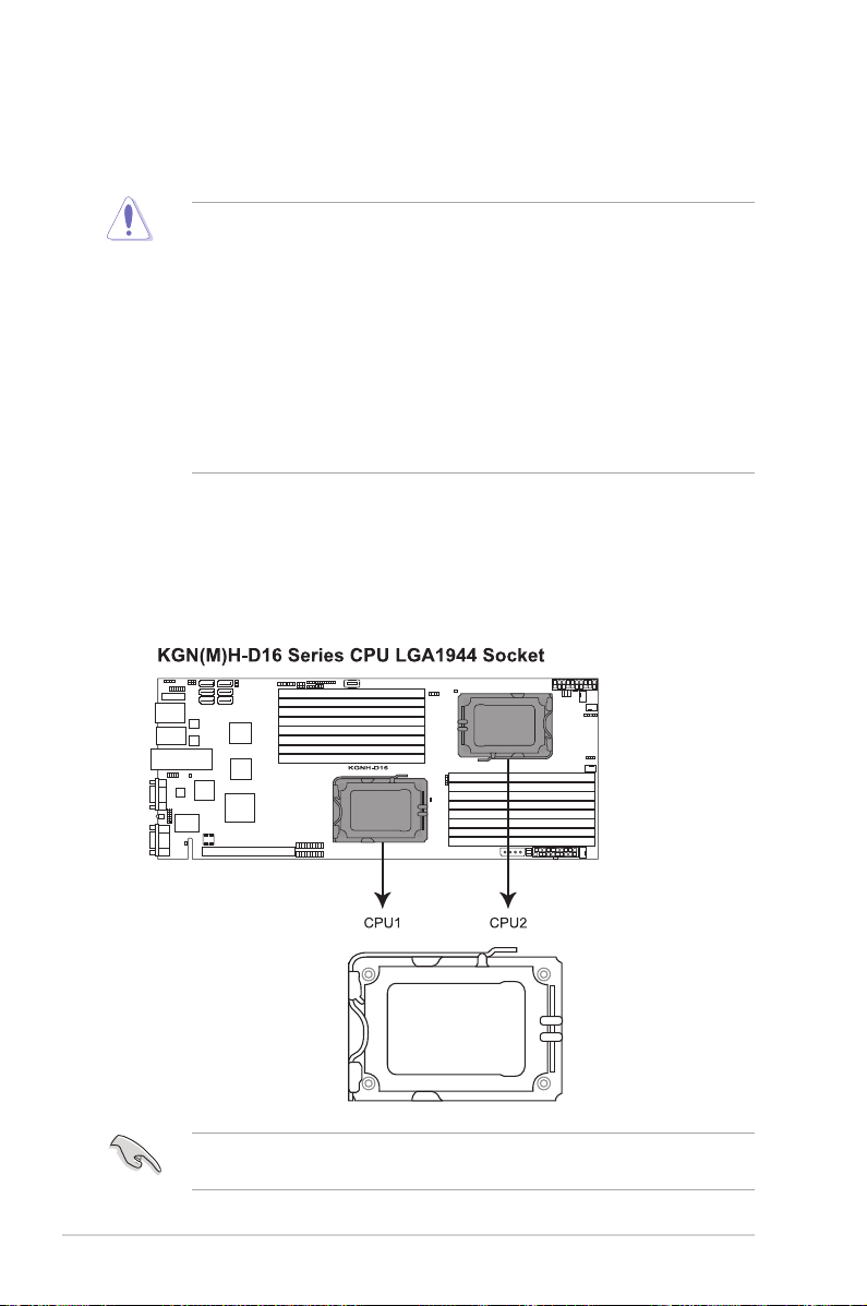
2.3 Central Processing Unit (CPU)
The motherboard comes with dual surface mount LGA 1944 Socket designed for
the AMD Opteron™ 6100 series CPU in the Land Grid Array (LGA) package.
• Upon purchase of the motherboard, ensure that the PnP cap is on
the socket and the socket contacts are not bent. Contact your retailer
immediately if the PnP cap is missing, or if you see any damage to the PnP
cap/socket contacts/motherboard components. ASUS shoulders the repair
cost only if the damage is shipment/transit-related.
• Keep the cap after installing the motherboard. ASUS will process Return
Merchandise Authorization (RMA) requests only if the motherboard comes
with the cap on the Socket 1944.
• The product warranty does not cover damage to the socket contacts
resulting from incorrect CPU installation/removal, or misplacement/loss/
incorrect removal of the PnP cap.
2.3.1 Installing the CPU
To install a CPU:
1. Locate the CPU socket on the motherboard.
Before installing the CPU, ensure that the socket box is facing toward you and
the load lever is on your left.
2-10 Chapter 2: Hardware information
Page 29
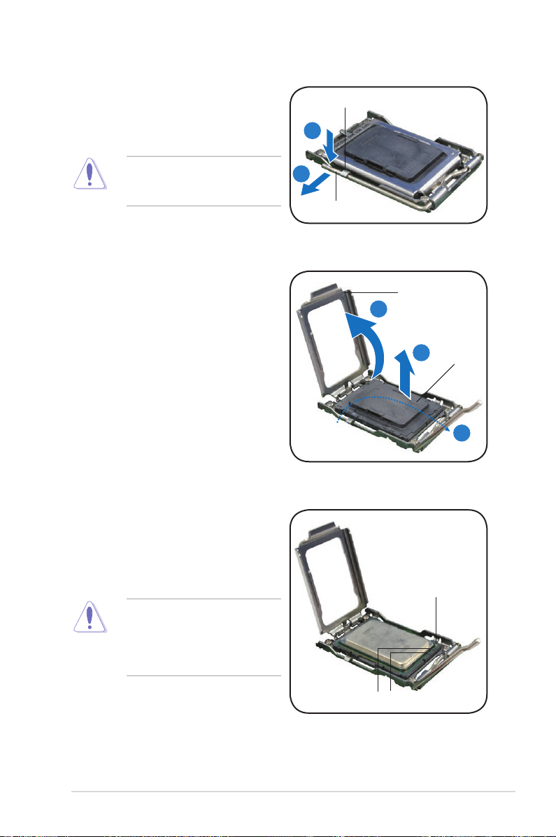
2. Press the load lever with your
thumb (A), then move it to the left
(B) until it is released from the
retention tab.
Retention tab
A
To prevent damage to the socket
pins, do not remove the PnP cap
unless you are installing a CPU.
3. Lift the load lever in the direction of
the arrow to a 135º angle.
4. Lift the load plate with your thumb
and forenger to a 100º angle.
5. Remove the PnP cap from the CPU
socket.
6. Position the CPU over the socket,
ensuring that the gold triangle is on
the bottom-right corner of the socket,
and then t the socket alignment key
into the CPU notch.
B
Load lever
Load plate
4
5
Gold triangle mark
PnP cap
3
The CPU ts in only one correct
orientation. DO NOT force the
CPU into the socket to prevent
bending the connectors on the
socket and damaging the CPU!
Alignment keys
ASUS KGN(M)H-D16 2-11
Page 30
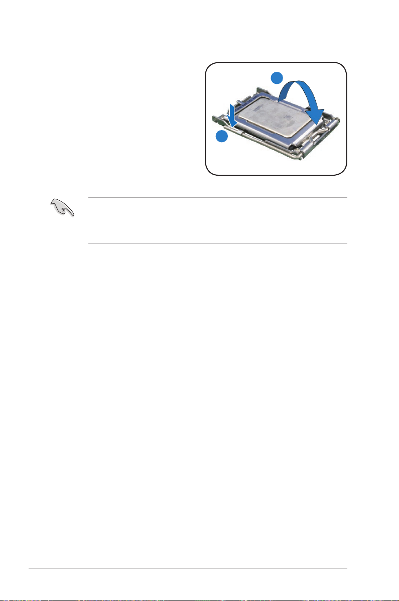
7. Close the load plate (A), then push
the load lever (B) until it snaps into
the retention tab.
Apply some Thermal Interface Material to the exposed area of the CPU that the
heatsink will be in contact with, ensuring that it is spread in an even thin layer.
Some heatsinks come with pre-applied Thermal Interface Material. If so, skip
this step.
A
B
2-12 Chapter 2: Hardware information
Page 31

2.3.2 Installing the CPU heatsink
The AMD Opteron™ 6100 series processors require a specially designed heatsink
to ensure optimum thermal condition and performance.
• Ensure to use qualied heatsink assembly with dimension 90mm x 90mm x
27mm only.
• Ensure that you have applied the thermal grease to the top of the CPU
before installing the heatsink and fan.
Follow these steps to install the CPU heatsink and fan.
1. Locate the heatsink standoffs on the motherboard.
2. Use a Phillips screwdriver to tighten the four heatsink screws in a diagonal
sequence, ensuring that the screw holes are matched with the heatsink
standoffs.
Ensure that the heatsink is not skewed or tilted, otherwise the CPU will overheat.
ASUS KGN(M)H-D16 2-13
Page 32

2.4 System memory
2.4.1 Overview
The motherboard comes with sixteen (16) Double Data Rate 3 (DDR3) Dual Inline
Memory Modules (DIMM) sockets.
A DDR3 module has the same physical dimensions as a DDR2 DIMM but is
notched differently to prevent installation on a DDR2 DIMM socket. DDR3 modules
are developed for better performance with less power consumption.
The gure illustrates the location of the DDR3 DIMM sockets:
2-14 Chapter 2: Hardware information
Page 33

2.4.2 Memory Congurations
You may install 1 GB, 2 GB, 4 GB, 8GB and 16GB registered DDR3 DIMMs or
1 GB, 2 GB, and 4 GB ECC/non-ECC, unbuffered DDR3 DIMMs into the DIMM
sockets using the memory congurations in this section.
Memory population table
For UDIMM (Single Rank, Dual Ranks)
CPU 1 Conguration
A2 A1 B2 B1 C2 C1 D2 D1 – – – – – – – –
2 DIMMs
4 DIMMs
6 DIMMs
8 DIMMs
CPU 1 + 2 Conguration
A2 A1 B2 B1 C2 C1 D2 D1 E2 E1 F2 F1 G2 G1 H2 H1
2 DIMMs
4 DIMMs
6 DIMMs
8 DIMMs
10 DIMMs
12 DIMMs
14 DIMMs
16 DIMMs
For RDIMM (Single Rank, Dual Ranks & Quad Ranks)
CPU 1 Conguration
A2 A1 B2 B1 C2 C1 D2 D1 – – – – – – – –
2 DIMMs
4 DIMMs
6 DIMMs
8 DIMMs
CPU 1 + 2 Conguration
A2 A1 B2 B1 C2 C1 D2 D1 E2 E1 F2 F1 G2 G1 H2 H1
2 DIMMs
4 DIMMs
6 DIMMs
8 DIMMs
10 DIMMs
12 DIMMs
14 DIMMs
16 DIMMs
ASUS KGN(M)H-D16 2-15
Page 34

• Always install DIMMs with the same CAS latency. For optimum
compatibility, it is recommended that you obtain memory modules from the
same vendor.
• For CPU1, install DIMMs to the blue slots in the order of: DIMM_A2 ->
DIMM_C2 -> DIMM_B2 -> DIMM_D2. For CPU1+CPU2, install DIMMs
to the blue slots in the order of: DIMM_A2 -> DIMM_E2 -> DIMM_C2 ->
DIMM_G2.
• For Quad Rank DIMMs, when installing less than or equal to four DIMMs,
install them to the blue slots in the order of: DIMM_A2 -> DIMM_C2 ->
DIMM_B2 -> DIMM_D2. For CPU1+CPU2, install DIMMs to the blue slots
in the order of: DIMM_A2 -> DIMM_E2 -> DIMM_C2 -> DIMM_G2.
• For Quad Rank DIMMs, when installing more than four DIMMs, install
them to the blue slots in the order of: DIMM_A2 -> DIMM_C2 -> DIMM_B2
-> DIMM_D2 -> DIMM_A1 -> DIMM_C1 -> DIMM_B1 -> DIMM_D1. For
CPU1+CPU2, install them to the blue slots in the order of: DIMM_A2
-> DIMM_E2 -> DIMM_C2 -> DIMM_G2 -> DIMM_B2 -> DIMM_F2 ->
DIMM_D2 -> DIMM_H2 -> DIMM_A1 -> DIMM_E1 -> DIMM_C1 ->
DIMM_G1 -> DIMM_B1 -> DIMM_F1 -> DIMM_D1 -> DIMM_H1.
2-16 Chapter 2: Hardware information
Page 35

2.4.3 Installing a DIMM
Ensure to unplug the power supply before adding or removing DIMMs or other
system components. Failure to do so may cause severe damage to both the
motherboard and the components.
1. Unlock a DIMM socket by
pressing the retaining clip
outward.
2. Align a DIMM on the socket
such that the notch on the DIMM
matches the DIMM slot key on the
socket.
A DIMM is keyed with a notch so that it ts in only one direction. DO NOT force
a DIMM into a socket in the wrong direction to avoid damaging the DIMM.
3. Hold the DIMM by both of its
ends, then insert the DIMM
vertically into the socket. Apply
force to both ends of the DIMM
simultaneously until the retaining
clip snaps back into place, and
the DIMM cannot be pushed
in any further to ensure proper
sitting of the DIMM.
Always insert the DIMM into the socket VERTICALLY to prevent DIMM notch
damage.
2.4.4 Removing a DIMM
DIMM notch
DIMM slot key
1
2
Unlocked retaining clip
3
Locked Retaining Clip
1. Press the retaining clip outward to
unlock the DIMM.
2. Remove the DIMM from the
socket.
ASUS KGN(M)H-D16 2-17
2
1
Page 36

2.5 Expansion slot
In the future, you may need to install expansion cards. The following sub-sections
describe the slot and the expansion cards that it supports.
Ensure to unplug the power cord before adding or removing expansion cards.
Failure to do so may cause you physical injury and damage motherboard
components.
• ASUS KGN(M)H-D16 server board supports Half-Height, Half-Length
expansion cards only.
• When installing the motherboard to a 1U/2U rackmount server system, rst
install the expansion card using an optional PCIe x16 riser card, then install
the riser card along with the expansion card to the onboard PCI Express
x16 slot.
2.5.1 Installing an expansion card
To install an expansion card:
1. Before installing the expansion card, read the documentation that came with
it and make the necessary hardware settings for the card.
2. Remove the system unit cover (if your motherboard is already installed in a
chassis).
3. Remove the bracket opposite the slot that you intend to use. Keep the screw
for later use.
4. Align the card connector with the slot and press rmly until the card is
completely seated on the slot.
5. Secure the card to the chassis with the screw you removed earlier.
6. Replace the system cover.
2.5.2 Conguring an expansion card
After installing the expansion card, congure the it by adjusting the software
settings.
1. Turn on the system and change the necessary BIOS settings, if any. See
Chapter 4 for information on BIOS setup.
2. Assign an IRQ to the card. Refer to the tables on the next page.
3. Install the software drivers for the expansion card.
When using PCI cards on shared slots, ensure that the drivers support “Share
IRQ” or that the cards do not need IRQ assignments. Otherwise, conicts will
arise between the two PCI groups, making the system unstable and the card
inoperable.
2-18 Chapter 2: Hardware information
Page 37

2.5.3 Interrupt assignments
Standard Interrupt assignments
IRQ Priority Standard function
0 1 System Timer
1 2 Keyboard Controller
2 - Programmable Interrupt
4* 12 Communications Port (COM1)
5* 13 --
6 14 Floppy Disk Controller
7* 15 --
8 3 System CMOS/Real Time Clock
9* 4 ACPI Mode when used
10* 5 IRQ Holder for PCI Steering
11* 6 IRQ Holder for PCI Steering
12* 7 PS/2 Compatible Mouse Port
13 8 Numeric Data Processor
14* 9 Primary IDE Channel
15* 10 Secondary IDE Channel
* These IRQs are usually available for ISA or PCI devices.
2.5.4 PCI Express x16 slot (x16 link)
The onboard PCI Express x16 slot provides x16 link to the AMD SP5100 chipset.
This slot supports VGA cards and various server class high performance add-on
cards.
PCIEx16 slot (x16 link)
When installing the motherboard to a 1U/2U rackmount server system, rst
install the expansion card using an optional PCIe x16 riser card, then install the
riser card along with the expansion card to the onboard PCI Express x16 slot.
ASUS KGN(M)H-D16 2-19
Page 38

2.5.5 Installing ASMB4 management board
Follow the steps below to install an optional ASMB4 management board on your
motherboard.
1. Locate the BMC_FW1 header on
the motherboard.
2. Orient and press the ASMB4
management card in place.
2-20 Chapter 2: Hardware information
Page 39

2.6 Jumpers
1. Clear RTC RAM (CLRTC1)
This jumper allows you to clear the Real Time Clock (RTC) RAM in CMOS.
You can clear the CMOS memory of date, time, and system setup parameters
by erasing the CMOS RTC RAM data. The onboard button cell battery
powers the RAM data in CMOS, which include system setup information such
as system passwords.
To erase the RTC RAM:
1. Turn OFF the computer and unplug the power cord.
2. Move the jumper cap from pins 1–2 (default) to pins 2–3. Keep the cap
on pins 2–3 for about 5–10 seconds, then move the cap back to pins 1–2.
3. Plug the power cord and turn ON the computer.
4. Hold down the <Del> key during the boot process and enter BIOS setup
to re-enter data.
Except when clearing the RTC RAM, never remove the cap on CLRTC jumper
default position. Removing the cap will cause system boot failure!
If the steps above do not help, remove the onboard battery and move the
jumper again to clear the CMOS RTC RAM data. After the CMOS clearance,
reinstall the battery.
ASUS KGN(M)H-D16 2-21
Page 40

2. VGA controller setting (3-pin VGA_SW1)
This jumper allows you to enable or disable the onboard VGA controller. Set
to pins 1–2 to activate the VGA feature.
3. DDR3 voltage control setting (4-pin LVDDR3_SEL1; LVDDR3_SEL2)
These jumpers allow you to adjust the DIMM voltage. Use LVDDR3_SEL1
to adjust the DIMM voltage for CPU 1, and use LVDDR3_SEL2 to adjust the
DIMM voltage for CPU 2. Set to pins 1–2 to select +1.5V BIOS control, pins 2–
3 to select Force +1.2V, or pins 3–4 to select Force +1.35V .
2-22 Chapter 2: Hardware information
Page 41

4. LAN controller setting (3-pin LAN_SW1, LAN_SW2)
These jumpers allow you to enable or disable the onboard Intel
®
Intel
82574LGigabit LAN controllers. Set to pins 1–2 to activate the Gigabit LAN
feature.
5. Chassis intrusion connector (2 pin CHASSIS)
This connector is for a chassis-mounted intrusion detection sensor or switch.
Connect one end of the chassis intrusion sensor or switch cable to this
connector. The chassis intrusion sensor or switch sends a high-level signal to
this connector when a chassis component is removed or replaced. The signal
is then generated as a chassis intrusion event.
By default , the pin labeled “Chassis Signal” and “Ground” are shorted with
a jumper cap. Remove the jumper caps only when you intend to use the
chassis intrusion detection feature.
ASUS KGN(M)H-D16 2-23
Page 42

6. Force BIOS recovery setting (3-pin RECOVERY1)
This jumper allows you to quickly update or recover the BIOS settings when it
becomes corrupted.
To update the BIOS:
1. Prepare a USB ash disk that contains the original or latest BIOS for the
motherboard.
2. Set the jumper to pins 2–3.
3. Insert the USB ash and turn on the system to update the BIOS.
4. Shut down the system.
5. Set the jumper back to pins 1–2.
6. Turn on the system.
2-24 Chapter 2: Hardware information
Page 43

7. IPMI setting (3-pin IPMI_SEL1). IPMI setting (3-pin IPMI_SEL1)
This jumper allows you to use the IPMI feature through the dedicated LAN
or share LAN. Place the jumper caps on pins 1–2 if you want to use IPMI
through the dedicated LAN (default). Or you can place the jumper caps on (default). Or you can place the jumper caps on
pins 2–3 to use IPMI through the shared LAN.through the shared LAN.
ASUS KGN(M)H-D16 2-25
Page 44

2.7 Connectors
2.7.1 Rear panel connectors
1. RJ-45 port for iKVM. This RJ-45 port functions only when you install ASMB4
management card.
2. LAN 2 (RJ-45) port. This port allows Gigabit connection to a Local Area
Network (LAN) through a network hub. Refer to the table below for the LAN
port LED indications.
3. USB 2.0 ports 1 and 2. These two 4-pin Universal Serial Bus (USB) ports
are available for connecting USB 2.0 devices.
4. LAN 1 (RJ-45) port. This port allows Gigabit connection to a Local Area
Network (LAN) through a network hub. Refer to the table below for the LAN
port LED indications.
LAN port LED indications
Activity/Link LED Speed LED
Status Description Status Description
OFF No link OFF 10 Mbps connection
GREEN Linked ORANGE 100 Mbps connection
BLINKING Data activity GREEN 1 Gbps connection
ACT/LINK
LED
LAN port
SPEED
LED
5. InniBand (QSFP).
(KGMH-D16/QDR only)
This port allows connection with
a QSFP cable to an InniBand switch.
6. Video Graphics Adapter port. This port is for a VGA monitor or other VGA-
compatible devices.
7. Location LED. This LED lights up for you to conveniently locate the system
in error.
8. Serial (COM1) port. This 9-pin communication port is for pointing devices or
other serial devices.
2-26 Chapter 2: Hardware information
Page 45

2.7.2 Internal connectors.7.2 Internal connectors
1. Serial ATA connectors (7-pin SATA1, SATA2, SATA3, SATA4, SATA5,
SATA6)
Supported by the AMD SP5100 chipset, these connectors are for the Serial
ATA signal cables for Serial ATA hard disk drives that allows up to 300 Mb/s
of data transfer rate.
The actual data transfer rate depends on the speed of Serial ATA hard disks
installed.
ASUS KGN(M)H-D16 2-27
Page 46

2. USB connectors (5-1 pin USB3; A-Type USB4)
These connectors are for USB 2.0 ports. Connect the USB module cables
to connectors USB3, then install the modules to a slot opening at the
back of the system chassis. These USB connectors comply with USB 2.0
specication that supports up to 480 Mbps connection speed.
3. Thermal sensor cable connectors (3-pin TR1, TR2)
These connectors are for temperature monitoring. Connect the thermal
sensor cables to these connectors and place the other ends to the devices,
which you want to monitor temperature.
2-28 Chapter 2: Hardware information
Page 47

4. Front fan connectors
(4-pin FRNT_FAN1, FRNT_FAN2, FRNT_FAN3, FRNT_FAN4)
The fan connectors support cooling fans of 350mA–1.75 A (21W max.) or
a total of 1.4A–7A (84W max.) at +12V. Connect the fan cables to the fan
connectors on the motherboard, ensuring that the black wire of each cable
matches the ground pin of the connector.
• DO NOT forget to connect the fan cables to the fan connectors. Insufcient
air ow inside the system may damage the motherboard components.
• These are not jumpers! DO NOT place jumper caps on the fan connectors!
• All fans feature the ASUS Smart Fan technology.
ASUS KGN(M)H-D16 2-29
Page 48

5. LPC debug card connector (14-1 pin LPC1)
This is a low pin count interface used to plug in the LPC debug card.
6. Serial General Purpose Input/Output connector (8-1 pin SGPIO1,
SGPIO2)
This connector connects to the SGPIO connector on the SATA HDD
backplane.
2-30 Chapter 2: Hardware information
Page 49

7. BMC header (BMC_FW1)
The BMC connector on the motherboard supports an ASUS® Server
Management Board 4 Series (ASMB4).
8. Power Supply SMBus connectors (6-1 pin JP1; JP2)
These connectors allow you to connect SMBus (System Management Bus) to
the power supply unit to read PSU information. Devices communicate with an
SMBus host and/or other SMBus devices using the SMBus interface.
ASUS KGN(M)H-D16 2-31
Page 50

9. Proprietary power connectors
(20-pin PWR1, 20-pin PWR2, 4-pin EZ_PLUG1)
These connectors are for Proprietary power supply plugs. The power supply
plugs are designed to t these connectors in only one orientation. Orient the
connectors and push down rmly until they completely t.
The 4-pin EZ_PLUG is designed for hard disk drives power supply. DO NOT
connect other 4-pin power connectors of the power supply unit (PSU) to this
connector.
• Connect either one of the 20-pin power connectors to boot up the system.
• Use of a PSU with a higher power output is recommended when conguring
a system with more power-consuming devices. The system may become
unstable or may not boot up if the power is inadequate.
• USE THE PROPRIETARY POWER SUPPLY ONLY; otherwise you may
damage the motherboard. Ensure that your PSU can provide at least the
minimum power required by your system.
2-32 Chapter 2: Hardware information
Page 51

10. HDD status indicator header (9-1 pin HSATAT1)
This connector is for the indicators at the back panel. The indicator lights up
when the corresponding SATA hard disk functions abnormally.
11. Hard disk activity LED connector (4-pin HDLED1). Hard disk activity LED connector (4-pin HDLED1)
This connector is used to connect to a hard disk drive active LED connector
on the SCSI or RAID card.
ASUS KGN(M)H-D16 2-33
Page 52

12. Internal VGA Header (10-1 pin VGA_HDR1). Internal VGA Header (10-1 pin VGA_HDR1)
This connector is used to connect an internal VGA output connector.
2-34 Chapter 2: Hardware information
Page 53

13. Auxiliary panel connector (20-pin AUX_PANEL1)
This connector is for additional front panel features including front panel
SMB, locator LED and switch, chassis intrusion, and LAN LEDs.
1. Front panel SMB (6-1 pin FPSMB)
These leads connect the front panel SMBus cable.
2. LAN activity LED (2-pin LAN1_LED, LAN2_LED)
These leads are for Gigabit LAN activity LEDs on the front panel.
3. Chassis intrusion (4-1 pin CHASSIS)
These leads are for the intrusion detection feature for chassis with
intrusion sensor or microswitch. When you remove any chassis
component, the sensor triggers and sends a high-level signal to these
leads to record a chassis intrusion event. The default setting is short
CASEOPEN and GND pin by jumper cap to disable the function.
4. Locator LED (2-pin LOCATORLED1 and 2-pin LOCATORLED2)
These leads are for the locator LED1 and LED2 on the front panel.
Connect the Locator LED cables to these 2-pin connector. The LEDs
will light up when the Locator button is pressed.
5. Locator Button/Swich (2-pin LOCATORBTN)
These leads are for the locator button on the front panel. This button
queries the state of the system locator.
ASUS KGN(M)H-D16 2-35
Page 54

14. System panel connector (20-pin PANEL1)
This connector supports several chassis-mounted functions.
• System power LED (3-pin PLED)
This 3-pin connector is for the system power LED. Connect the chassis power
LED cable to this connector. The system power LED lights up when you turn
on the system power, and blinks when the system is in sleep mode.
• Message LED (2-pin MLED)
This 2-pin connector is for the message LED cable that connects to the
front message LED. The message LED is controlled by Hardware monitor to
indicate an abnormal event occurance.
• Hard disk drive activity LED (2-pin HDDLED)
This 2-pin connector is for the HDD Activity LED. Connect the HDD Activity
LED cable to this connector. The IDE LED lights up or ashes when data is
read from or written to the HDD.
• Proprietary power button/soft-off button (2-pin PWRSW)
This connector is for the system power button. Pressing the power button
turns the system on or puts the system in sleep or soft-off mode depending
on the BIOS settings. Pressing the power switch for more than four seconds
while the system is ON turns the system OFF.
• Reset button (2-pin RESET)
This 2-pin connector is for the chassis-mounted reset button for system
reboot without turning off the system power.
2-36 Chapter 2: Hardware information
Page 55

This chapter describes the power up
sequence, and ways of shutting down the
system.
Powering up
3
Page 56

Chapter summary
3
3.1 Starting up for the rst time ........................................................ 3-3
3.2 Turning off the computer ............................................................. 3-4
ASUS KGN(M)H-D16
Page 57

3.1 Starting up for the rst time
1. After making all the connections, replace the system case cover.
2. Ensure that all switches are off.
3. Connect the power cord to the power connector at the back of the system
chassis.
4. Connect the power cord to a power outlet that is equipped with a surge
protector.
5. Turn on the devices in the following order:
a. Monitor
b. External SCSI devices (starting with the last device on the chain)
c. System power
6. After applying power, the system power LED on the system front panel case
lights up. For systems with Proprietary power supplies, the system LED lights
up when you press the Proprietary power button. If your monitor complies
with “green” standards or if it has a “power standby” feature, the monitor LED
may light up or switch between orange and green after the system LED turns
on.
The system then runs the power-on self-test or POST. While the tests are
running, the BIOS beeps or additional messages appear on the screen. If you
do not see anything within 30 seconds from the time you turned on the power,
the system may have failed a power-on test. Check the jumper settings and
connections or call your retailer for assistance.
7. At power on, hold down the <Del> key to enter the BIOS Setup. Follow the
instructions in Chapter 4.
ASUS KGN(M)H-D16 3-3
Page 58

3.2 Powering off the computer
3.2.1 Using the OS shut down function
If you are using Windows® 2000/2003 Server:
1. Click
2. Select
box.
3. Select
4. Ensure that the
5. Select
6. If necessary, key in comments.
7. Click OK.
then click
Start
Shut Down
Shutdown Event Tracker
shutdown
Shut Down
from the
Planned
from the list box.
What do you want the computer to do?
check box is checked.
.
list
.
3.2.2 Using the dual function power switch
While the system is ON, pressing the power switch for less than four seconds puts
the system to sleep mode or to soft-off mode, depending on the BIOS setting.
Pressing the power switch for more than four seconds lets the system enter the
soft-off mode regardless of the BIOS setting. Refer to section
Chapter 4 for details.
4.6 Power Menu
in
3-4 Chapter 3: Powering up
Page 59

This chapter tells how to change the
system settings through the BIOS Setup
menus. Detailed descriptions of the BIOS
parameters are also provided.
BIOS setup
4
Page 60

Chapter summary
4
4.1 Managing and updating your BIOS ............................................ 4-3
4.2 BIOS setup program .................................................................... 4-7
4.3 Main menu .................................................................................. 4-10
4.4 Advanced menu ......................................................................... 4-15
4.5 Server menu ............................................................................... 4-27
4.6 Power menu ................................................................................ 4-29
4.7 Boot menu .................................................................................. 4-32
4.8 Tools menu ................................................................................. 4-36
4.9 Exit menu .................................................................................... 4-37
ASUS KGN(M)H-D16
Page 61

4.1 Managing and updating your BIOS
The following utilities allow you to manage and update the motherboard Basic
Input/Output System (BIOS) setup:
1.
ASUS EZ Flash 2
2.
BUPDATER utility
(Updates the BIOS using a USB ash disk.)
(Updates the BIOS in DOS mode using a bootable USB
ash disk drive.)
3.
ASUS CrashFree BIOS 3
(To recover the BIOS using a bootable USB ash
disk drive when the BIOS le fails or gets corrupted.)
Refer to the corresponding sections for details on these utilities.
Save a copy of the original motherboard BIOS le to a bootable
disk drive
motherboard BIOS using the BUPDATER utility.
in case you need to restore the BIOS in the future. Copy the original
USB ash
4.1.1 ASUS EZ Flash 2 utility
The ASUS EZ Flash 2 feature allows you to update the BIOS without having to use
a DOS-based utility.
Before you start using this utility, download the latest BIOS from the ASUS
website at www.asus.com.
To update the BIOS using EZ Flash 2
1. Insert the USB ash disk that contains the latest BIOS le to the USB port.
2. Enter the BIOS setup program. Go to the
and press <Enter> to enable it.
Or, press <Alt> + <F2> during the POST to enable EZ Flash 2.
menu to select
Tools
EZ Flash 2
ASUSTek EZ Flash 2 BIOS ROM Utility V4.16
FLASH TYPE: MXIC 25L1605A
Current ROM
BOARD: KGNH-D16
VER: 0204
DATE: 05/31/2010
PATH: A:\
A:
Note
[Enter] Select or Load [Tab] Switch [V] Drive Info
[Up/Down/Home/End] Move [B] Backup [Esc] Exit
ASUS KGN(M)H-D16 4-3
Update ROM
BOARD: Unknown
VER: Unknown
DATE: Unknown
Page 62

3. Press <Tab> to switch between drives until the correct BIOS le is
found. When found, EZ Flash 2 performs the BIOS update process and
automatically reboots the system when done.
• This function can support devices such as a USB ash disk with FAT 32/16
format and single partition only.
• DO NOT shut down or reset the system while updating the BIOS to prevent
system boot failure!
Ensure to load the BIOS default settings to ensure system compatibility and
stability. Select the Load Setup Defaults item under the Exit menu. See
section 4.9 Exit Menu for details.
4.1.2 BUPDATER utility
The succeeding BIOS screens are for reference only. The actual BIOS screen
displays may not be the same as shown.
The BUPDATER utility allows you to update the BIOS le in DOS environment
using a bootable USB ash disk drive with the updated BIOS le.
Updating the BIOS le
To update the BIOS le using the BUPDATER utility:
1. Visit the ASUS website at www.asus.com and download the latest BIOS le
for the motherboard. Save the BIOS le to a bootable USB ash disk drive. USB ash disk drive..
2. Copy the BUPDATER utility (BUPDATER.exe) from the ASUS support
website at support.asus.com to the bootable USB ash disk drive you created USB ash disk drive you createdyou created
earlier.
3. Boot the system in DOS mode, then at the prompt, type:
BUPDATER /i[lename].ROM
where [lename] is the latest or the original BIOS le on the bootable USB USB
ash disk drive, then press <Enter>., then press <Enter>.
A:\>BUPDATER /i[le name].ROM
4-4 Chapter 4: BIOS setup
Page 63

4. The utility veries the le, then starts updating the BIOS le.
ASUSTek BIOS Update for DOS V1.06 (09/08/04)
FLASH TYPE: MXIC 25L1605A
Current ROM
BOARD: KGNH-D16
VER: 0204
DATE: 05/31/2010
PATH:
WARNING! Do not turn off power during ash BIOS
Note
Writing BIOS:
Update ROM
BOARD: KGNH-D16
VER: 0206
DATE: 06/10/2009
DO NOT shut down or reset the system while updating the BIOS to prevent
system boot failure!
5. The utility returns to the DOS prompt after the BIOS update process is
completed. Reboot the system from the hard disk drive.
The BIOS update is nished! Please restart your system.
C:\>
ASUS KGN(M)H-D16 4-5
Page 64

4.1.3 ASUS CrashFree BIOS 3 utility
The ASUS CrashFree BIOS 3 is an auto recovery tool that allows you to restore
the BIOS le when it fails or gets corrupted during the updating process. You can
update a corrupted BIOS le using a USB ash drive that contains the updated
BIOS le.
Prepare a USB ash drive containing the updated motherboard BIOS before
using this utility.
Recovering the BIOS from a USB ash drive
To recover the BIOS from a USB ash drive:
1. Remove any oppy disk from the oppy disk drive and turn the system on.
2. Insert the USB ash drive with the original or updated BIOS le to one USB
port on the system.
3. The utility will automatically recover the BIOS. It resets the system when the
BIOS recovery nished.
DO NOT shut down or reset the system while recovering the BIOS! Doing so
would cause system boot failure!
The recovered BIOS may not be the latest BIOS version for this motherboard.
Visit the ASUS website at www.asus.com to download the latest BIOS le.
4-6 Chapter 4: BIOS setup
Page 65

4.2 BIOS setup program
This motherboard supports a programmable rmware chip that you can update
using the provided utility described in section
.
BIOS
Use the BIOS Setup program when you are installing a motherboard, reconguring
your system, or prompted to “Run Setup.” This section explains how to congure
your system using this utility.
Even if you are not prompted to use the Setup program, you can change the
conguration of your computer in the future. For example, you can enable the
security password feature or change the power management settings. This
requires you to recongure your system using the BIOS Setup program so that the
computer can recognize these changes and record them in the CMOS RAM of the
rmware chip.
The rmware chip on the motherboard stores the Setup utility. When you start up
the computer, the system provides you with the opportunity to run this program.
Press <Del> during the Power-On Self-Test (POST) to enter the Setup utility;
otherwise, POST continues with its test routines.
If you wish to enter Setup after POST, restart the system by pressing
<Ctrl+Alt+Delete>, or by pressing the reset button on the system chassis. You can
also restart by turning the system off and then back on. Do this last option only if
the rst two failed.
The Setup program is designed to make it as easy to use as possible. Being a
menu-driven program, it lets you scroll through the various sub-menus and make
your selections from the available options using the navigation keys.
4.1 Managing and updating your
• The default BIOS settings for this motherboard apply for most conditions
to ensure optimum performance. If the system becomes unstable after
changing any BIOS settings, load the default settings to ensure system
compatibility and stability. Select the
Exit Menu. See section
• The BIOS setup screens shown in this section are for reference purposes
only, and may not exactly match what you see on your screen.
• Visit the ASUS website at www.asus.com to download the latest BIOS le
for this motherboard.
ASUS KGN(M)H-D16 4-7
4.9 Exit Menu
Load Setup Defaults
.
item under the
Page 66

4.2.1 BIOS menu screen
Menu bar
Main Advanced Server Power Boot Tools Exit
System Time [17:44:30]
System Date [Mon, 03/08/2010]
SATA 1 : [ST3160812AS]
SATA 2 : [Not Detected]
SATA 3 : [Not Detected]
SATA 4 : [Not Detected]
SATA 5 : [Not Detected]
SATA 6 : [Not Detected]
Storage Conguration
System Information
v02.61 (C)Copyright 1985-2010, American Megatrends, Inc.
Sub-menu items
Conguration eldsMenu items
BIOS SETUP UTILITY
General help
Use [ENTER], [TAB]
or [SHIFT-TAB] to
select a eld.
Use [+] or [-] to
congure system Date.
←→ Select Screen
↑↓ Select Item
+- Change Field
Tab Select Field
F1 General Help
F10 Save and Exit
ESC Exit
Navigation keys
4.2.2 Menu bar
The menu bar on top of the screen has the following main items:
Main For changing the basic system conguration
Advanced For changing the advanced system settings
Server For changing the advanced server settings
Power For changing the advanced power management (APM)
conguration
Boot For changing the system boot conguration
For conguring options for special functions
Tools
Exit For selecting the exit options and loading default
settings
To select an item on the menu bar, press the right or left arrow key on the keyboard
until the desired item is highlighted.
4.2.3 Navigation keys
At the bottom right corner of a menu screen are the navigation keys for that
particular menu. Use the navigation keys to select items in the menu and change
the settings.
Some of the navigation keys differ from one screen to another.
4-8 Chapter 4: BIOS setup
Page 67

4.2.4 Menu items
The highlighted item on the menu bar displays the specic items for that menu. For
example, selecting Main shows the Main menu items.
The other items (Advanced, Power, Boot, and Exit) on the menu bar have their
respective menu items.
4.2.5 Sub-menu items
A solid triangle before each item on any menu screen means that the item has a
sub-menu. To display the sub-menu, select the item and press <Enter>.
4.2.6 Conguration elds
These elds show the values for the menu items. If an item is user-congurable,
you can change the value of the eld opposite the item. You cannot select an item
that is not user-congurable.
A congurable eld is enclosed in brackets, and is highlighted when selected. To
change the value of a eld, select it then press <Enter> to display a list of options.
Refer to 4.2.7 Pop-up window.
4.2.7 Pop-up window
Select a menu item then press <Enter>
to display a pop-up window with the
conguration options for that item.
Main Advanced Server Power Boot Tools Exit
Suspend Mode [Auto]
ACPI Version Features [Disabled]
ACPI APIC support [Enabled]
APM Conguration
Hardware Monitor
4.2.8 Scroll bar
A scroll bar appears on the right side of
a menu screen when there are items that
do not t on the screen. Press the Up/
Down arrow keys or <Page Up> /<Page
Down> keys to display the other items on the screen.
v02.61 (C)Copyright 1985-2010, American Megatrends, Inc.
BIOS SETUP UTILITY
Disabled
Enabled
Scroll bar
Pop-up window
Use [ENTER], [TAB] or
[SHIFT-TAB] to select
a eld.
Use [+] or [-] to
congure system Time.
←→ Select Screen
↑↓ Select Item
+- Change Field
Tab Select Field
F1 General Help
F10 Save and Exit
ESC Exit
4.2.9 General help
At the top right corner of the menu screen is a brief description of the selected
item.
ASUS KGN(M)H-D16 4-9
Page 68

4.3 Main menu
When you enter the BIOS Setup program, the Main menu screen appears, giving
you an overview of the basic system information.
Refer to section 4.2.1 BIOS menu screen for information on the menu screen
items and how to navigate through them.
Main Advanced Server Power Boot Tools Exit
System Time [17:44:30]
System Date [Mon, 05/31/2010]
SATA 1 : [ST3160812AS]
SATA 2 : [Not Detected]
SATA 3 : [Not Detected]
SATA 4 : [Not Detected]
SATA 5 : [Not Detected]
SATA 6 : [Not Detected]
Storage Conguration
System Information
v02.61 (C)Copyright 1985-2010, American Megatrends, Inc.
BIOS SETUP UTILITY
Use [ENTER], [TAB]
or [SHIFT-TAB] to
select a eld.
Use [+] or [-] to
congure system Date.
←→ Select Screen
↑↓ Select Item
+- Change Field
Tab Select Field
F1 General Help
F10 Save and Exit
ESC Exit
4.3.1 System Time [xx:xx:xx]
Allows you to set the system time.
4.3.2 System Date [Day xx/xx/xxxx]
Allows you to set the system date.
4.3.3 SATA1—6
While entering Setup, the BIOS automatically detects the presence of IDE/SATA
devices. There is a separate submenu for each IDE/SATA device. Select a device
item then press <Enter> to display the SATA device information.
Main
SATA1
Device :Hard Disk
Vendor :xxxxxxxxx
Size :xx.xGB
LBA Mode :Supported
Block Mode:16Sectors
PIO Mode :4
Async DMA :MultiWord DMA-2
Ultra DMA :Ultra DMA-6
S.M.A.R.T.:Supported
LBA/Large Mode [Auto]
Block(Multi-Sector Transfer)M [Auto]
PIO Mode [Auto]
DMA Mode [Auto]
SMART Monitoring [Auto]
32Bit Data Transfer [Enabled]
v02.61 (C)Copyright 1985-2009, American Megatrends, Inc.
BIOS SETUP UTILITY
Disabled: Disabled LBA
Mode.
Auto: Enables LBA
Mode if the device
supports it and the
device is not already
formatted with LBA
Mode disabled.
←→ Select Screen
↑↓ Select Item
+- Change Option
F1 General Help
F10 Save and Exit
ESC Exit
4-10 Chapter 4: BIOS setup
Page 69

The BIOS automatically detects the values opposite the dimmed items (Device,
Vendor, Size, LBA Mode, Block Mode, PIO Mode, Async DMA, Ultra DMA, and
S.M.A.R.T. monitoring). These values are not user-congurable. These items show
N/A if no IDE device is installed in the system.
LBA/Large Mode [Auto]
Enables or disables the LBA mode. Setting to [Auto] enables the LBA mode if the
device supports this mode, and if the device was not previously formatted with LBA
mode disabled. Conguration options: [Disabled] [Auto]
Block (Multi-Sector Transfer) M [Auto]
Enables or disables data multi-sectors transfers. When set to [Auto], the data
transfer from and to the device occurs multiple sectors at a time if the device
supports multi-sector transfer feature. When set to [Disabled], the data transfer
from and to the device occurs one sector at a time.
Conguration options: [Disabled] [Auto]
PIO Mode [Auto]
Allows you to select the data transfer mode.
Conguration options: [Auto] [0] [1] [2] [3] [4]
DMA Mode [Auto]
Sets the DMA mode.
Conguration options: [Auto] [SWDMA0] [SWDMA1] [SWDMA2] [MWDMA0]
[MWDMA1] [MWDMA2] [UDMA0] [UDMA1] [UDMA2] [UDMA3] [UDMA4] [UDMA5]
SMART Monitoring [Auto]
Sets the Smart Monitoring, Analysis, and Reporting Technology.
Conguration options: [Auto] [Disabled] [Enabled]
32Bit Data Transfer [Enabled]
Enables or disables 32-bit data transfer.
Conguration options: [Disabled] [Enabled]
ASUS KGN(M)H-D16 4-11
Page 70

4.3.4 Storage Conguration
The items in this menu allow you to set or change the congurations for the
IDE/SATA devices installed in the system. Select an item then press <Enter> if you
wish to congure the item.
Main
Storage Conguration
OnChip SATA Channel [Enabled]
SATA Port1- Port4 [IDE]
SATA Port5- Port6 [IDE]
v02.61 (C)Copyright 1985-2010, American Megatrends, Inc.
OnChip SATA Channel [Enabled]
Conguration options: [Disabled] [Enabled]
SATA Port1-Port4 [IDE]
Allows you to set the SATA conguration.
[IDE] Set to [IDE] when you want to use the Serial ATA hard disk drives
as Parallel ATA physical storage devices.
[RAID] Set to [RAID] when you want to create a RAID conguration from
the SATA hard disk drives.
[AHCI] Set to [AHCI] when you want the SATA hard disk drives to use the
AHCI (Advanced Host Controller Interface). The AHCI allows the
onboard storage driver to enable advanced Serial ATA features that
increases storage performance on random workloads by allowing
the drive to internally optimize the order of commands.
SATA Port5-Port6
Setting this item to [IDE] instead of [RAID] or [AHCI] allows the system to
recognize the optical drives connected to the SATA connectors 5 or 6 when
installing OS.
BIOS SETUP UTILITY
Options
Disabled
Enabled
←→ Select Screen
↑↓ Select Item
+- Change Option
F1 General Help
F10 Save and Exit
ESC Exit
If SATA Port1-Port4 is set to [IDE], SATA Port5-Port6 can only be congured as
[IDE]
4-12 Chapter 4: BIOS setup
Page 71

4.3.5 System Information
This menu gives you an overview of the general system specications. The BIOS
automatically detects the items in this menu.
Main
BIOS Information
Version :0206
Build Date :06/25/10
Processor
Type :AMD Opteron(tm) Processor 6128
Speed :2000MHz
System Memory
Usable Size : 2040MB
System Memory Information
v02.61 (C)Copyright 1985-2010, American Megatrends, Inc.
BIOS Information
Displays the auto-detected BIOS information.
Processor
Displays the auto-detected CPU specication.
System Memory
Displays the auto-detected system memory.
BIOS SETUP UTILITY
←→ Select Screen
↑↓ Select Item
Enter Go to Sub Screen
F1 General Help
F10 Save and Exit
ESC Exit
System Memory Information
Displays system memory information.
Main
System Memory Information
CPU1 Memory Information
CPU2 Memory Information
CPU1/2 Memory Configuration
Allows you to check information of installed memory (8 DIMMs per CPU).
ASUS KGN(M)H-D16 4-13
BIOS SETUP UTILITY
Page 72

CPU1/2 Memory Conguration
Displays the auto-detected memory specication.
Main
CPU1 Memory Conguration
Node0 Speed DDR3 1067
Node1 Speed N/A
DIMM_A1 N/A
DIMM_A2 2048 MB, 1R, 1067
DIMM_B1 N/A
DIMM_B2 N/A
DIMM_C1 N/A
DIMM_C2 N/A
DIMM_D1 N/A
DIMM_D2 N/A
BIOS SETUP UTILITY
4-14 Chapter 4: BIOS setup
Page 73

4.4 Advanced menu
The Advanced menu items allow you to change the settings for the CPU and other
system devices.
Take caution when changing the settings of the Advanced menu items. Incorrect
eld values can cause the system to malfunction.
Main Advanced Server Power Boot Tools Exit
CPU Conguration
Chipset
Onboard Device Conguration
USB Conguration
PCIPnP
v02.61 (C)Copyright 1985-2010, American Megatrends, Inc.
BIOS SETUP UTILITY
Congure CPU.
←→ Select Screen
↑↓ Select Item
Enter Go to Sub Screen
F1 General Help
F10 Save and Exit
ESC Exit
4.4.1 CPU Conguration
The items in this menu show the CPU-related information that the BIOS
automatically detects. Some items may not appear if your CPU does not support
the related functions.
Advanced
CPU Conguration
Module Version:5.1102.1
Physical Count:2
Logical Count :8
AMD Opteron(tm) Processor 6128
Revision: D1
Cache L1: 1024KB
Cache L2: 4096KB
Cache L3: 12MB
Speed : 2000MHz, NB Clk: 1800MHz
Able to Change Freq. : Yes
uCode Patch Level : 0x10000C4
GART Error Reporting [Disabled]
Microcode Updation [Enabled]
Secure Virtual Machine Mode [Enabled]
PowerNow [Enabled]
PowerCap [P-state 0]
ACPI SRAT Table [Enabled]
C1E Support [Enabled]
CPU2 [Enabled]
v02.61 (C)Copyright 1985-2010, American Megatrends, Inc.
BIOS SETUP UTILITY
This option should
remain disabled for the
normal operation. The
driver developer may
enable it for tetsting
purpose.
←→ Select Screen
↑↓ Select Item
+- Change Option
F1 General Help
F10 Save and Exit
ESC Exit
ASUS KGN(M)H-D16 4-15
Page 74

GART Error Reporting [Disabled]
Conguration options: [Disabled] [Enabled]
Microcode Updation [Enabled]
Conguration options: [Disabled] [Enabled]
Secure Virtual Machine Mode [Enabled]
Allows you to enable or diable the Secure Virtual Machine Mode (SVM).
Conguration options: [Disabled] [Enabled]
PowerNow [Enabled]
Allows you to enable or diable the generation of ACPI_PPC, ACPI_PSS, and
ACPI_PCT objects. Conguration options: [Disabled] [Enabled]
PowerCap [P-state 0]
Allows you to decide the highest performance P-state in OS.
Conguration options: [P-state 0] [P-state 1] [P-state 2] [P-state 3] [P-state 4]
ACPI SRAT Table [Enabled]
Enables or diables the building of ACPI SRAT Table.
Conguration options: [Disabled] [Enabled]
C1E Support [Enabled]
Allows you to enable or disable Enhanced Halt State support.
Conguration options: [Disabled] [Enabled]
CPU2 [Enabled]
Allows you to enable or diable the CPU2 function.
Conguration options: [Disabled] [Enabled]
4-16 Chapter 4: BIOS setup
Page 75

4.4.2 Chipset Conguration
The Chipset conguration menu allows you to change advanced chipset settings.
Select an item then press <Enter> to display the sub-menu.
For KGNH-D16:
Advanced
Advanced Chipset Settings
NorthBridge Conguration
SouthBridge Conguration
SR5650 Conguration
BIOS SETUP UTILITY
Options for NB
For KGMH-D16/QDR:
Advanced
Advanced Chipset Settings
NorthBridge Conguration
SouthBridge Conguration
SR5670 Conguration
BIOS SETUP UTILITY
Options for NB
NorthBridge Conguration
BIOS SETUP UTILITY
Advanced
Advanced
CPU Bridge Chipset Conguration
NorthBridge Chipset Conguration
CPU REVISION :B0
Memory Conguration
Current CSI Frequency :6.400GT
ECC Conguration
Current Memory Frequency :1066 Mhz
DRAM Timing Conguration
CSI Links Speed [Full-Speed]
Memory Timing Parameters [CPU Node 0]
CSI Frequency [Auto]
Memory Frequency [Auto]
Memory CLK :533 MHz, N/A
Memory Mode [Independent]
CAS Latency(Tcl) :7 CLK , N/A
Demand Scrubbing [Disabled]
RAS/CAS Delay(Trcd) :7 CLK , N/A
Patrol Scrubbing [Disabled]
Row Precharge Time(Trp) :7 CLK , N/A
Throttling - Closed Loop [Disabled]
Min Active RAS(Tras) :20 CLK , N/A
Throttling - Open Loop [Disabled]
RAS/RAS Delay(Trrd) :4 CLK , N/A
Row Cycle(Trc) :27 CLK , N/A
Read to Precharge(Trtp) :4 CLK , N/A
Write Recover Time(Twr) :8 CLK , N/A
v02.61 (C)Copyright 1985-2008, American Megatrends, Inc.
v02.61 (C)Copyright 1985-2010, American Megatrends, Inc.
BIOS SETUP UTILITY
To transition the CSI
links to full-speed
or leave them in
slow-mode.
←→ Select Screen
←→ Select Screen
↑↓ Select Item
↑↓ Select Item
+- Change Option
+- Change Option
F1 General Help
F1 General Help
F10 Save and Exit
F10 Save and Exit
ESC Exit
ESC Exit
ASUS KGN(M)H-D16 4-17
Page 76

Memory Conguration
Advanced
Memory Conguration
Bank Interleaving [Auto]
Node Interleaving [Disabled]
Channel Interleaving [Auto]
CS Sparing Enabled [Disabled]
Bank Swizzle Mode [Enabled]
Rank Interleaving [Auto]
Allows you to set the rank memory interleaving setting.
Conguation options: [Disabled] [Auto]
Node Interleaving [Disabled]
Allows you to set the node memory interleaving setting.
Conguation options: [Disabled] [Auto]
Channel Interleaving [Auto]
Allows you to set the channel memory interleaving setting.
Conguation options: [Disabled] [Auto]
CS Sparing Enable [Disabled]
Allows you to reserve a spare memory rank in each node.
Conguation options: [Disabled] [Enabled]
Bank Swizzle Mode [Enabled]
Allows you to enable or disable the bank swizzle mode.
Conguation options: [Disabled] [Enabled]
BIOS SETUP UTILITY
ECC Conguration
Advanced
ECC Conguration
ECC Mode [Basic]
DRAM ECC Enable [Enabled]
DRAM SCRUB REDIRECT [Disabled]
4-Bit ECC Mode [Enabled]
DRAM BG Scrub [Disabled]
Data Cache BG Scrub [Disabled]
L2 Cache BG Scrub [Disabled]
L3 Cache BG Scrub [Disabled]
ECC Mode [Disabled]
Disables or sets the DRAM ECC mode that allows the hardware to report and
correct memory errors.
[Disabled] Disables the DRAM ECC mode.
[Basic] Set to [Basic] to adjust ECC mode automatically.
[Good] Set to [Good] to adjust ECC mode automatically.
4-18 Chapter 4: BIOS setup
BIOS SETUP UTILITY
Page 77

[Super] Set to [Super] to adjust the DRAM BG Scrub sub-item manually.
[Max] Set to [Max] to adjust ECC mode automatically.
[User] Set to [User] to adjust all the subitems manually.
The following items become user-congurable when you set ECC Mode to
[User]
DRAM ECC Enable [Enabled]
[Enabled] Enables the DRAM ECC that allows the hardware to report and correct
memory errors automatically.
[Disabled] Disables this function.
DRAM SCRUB REDIRECT [Disabled]
[Enabled] Allows the system to correct the DRAM ECC errors immediately when
they occur.
[Disabled] Disables this function.
4-Bit ECC Mode [Disabled]
[Enabled] Enables ECC chip kill feature.
[Disabled] Disables this function.
DRAM BG SCRUB [Disabled]
Disables or sets the DRAM BG Scrub.
Conguration options: [Disabled] [40ns] [80ns] [160ns] [320ns] [640ns] [1.28us]
[2.56us] [5.12us] [10.2us] [20.5us] [41.0us] [81.9us] [163.8us] [327.7us] [655.4us]
[1.31ms] [2.62ms] [5.24ms] [10.49ms] [20.97ms] [42.00ms] [84.00ms]
Data Cache BG Scrub [Disabled]
Disables or sets the Data Cache BG Scrub. This item allows the data cache BG
Scrub RAM to be corrected when idle.
Conguration options: [Disabled] [40ns] [80ns] [160ns] [320ns] [640ns] [1.28us]
[2.56us] [5.12us] [10.2us] [20.5us] [41.0us] [81.9us] [163.8us] [327.7us] [655.4us]
[1.31ms] [2.62ms] [5.24ms] [10.49ms] [20.97ms] [42.00ms] [84.00ms]
L2 Cache BG Scrub [Disabled]
Disables or sets the L2 Cache BG Scrub. This item allows the cache RAM to be
corrected when idle.
Conguration options: [Disabled] [40ns] [80ns] [160ns] [320ns] [640ns] [1.28us]
[2.56us] [5.12us] [10.2us] [20.5us] [41.0us] [81.9us] [163.8us] [327.7us] [655.4us]
[1.31ms] [2.62ms] [5.24ms] [10.49ms] [20.97ms] [42.00ms] [84.00ms]
L3 Cache BG Scrub [Disabled]
Disables or sets the L3 Cache BG Scrub. This item allows the cache RAM to be
corrected when idle.
Conguration options: [Disabled] [40ns] [80ns] [160ns] [320ns] [640ns] [1.28us]
[2.56us] [5.12us] [10.2us] [20.5us] [41.0us] [81.9us] [163.8us] [327.7us] [655.4us]
[1.31ms] [2.62ms] [5.24ms] [10.49ms] [20.97ms] [42.00ms] [84.00ms]
ASUS KGN(M)H-D16 4-19
Page 78

DRAM Timing Conguration
BIOS SETUP UTILITY
Advanced
Advanced
DRAM Timing Conguration
DRAM Timing Cong [Auto]
BIOS SETUP UTILITY
Auto
Manual
DRAM Timing Config [Auto]
Conguration options: [Auto] [Manual]
Memory Clock Speed [400 MHz]
Allows you to set the memory clock frequency. This item available only when you set
DRAM Timing Cong
Conguration options: [400 MHz] [533 MHz] [667 MHz]
to [Manual].
Memory Timing Parameters [CPU Node 0]
Allows you to select which node's timing parameters to display.
SouthBridge Conguration
Advanced
SouthBridge Chipset Conguration
SP5100 CIMx Version : 5.5.0
SB Debug Conguration
OHCI HC (Bus 0 Dev 18 Fn 0) [Enabled]
OHCI HC (Bus 0 Dev 18 Fn 1) [Enabled]
EHCI HC (Bus 0 Dev 18 Fn 2) [Enabled]
OHCI HC (Bus 0 Dev 19 Fn 0) [Enabled]
OHCI HC (Bus 0 Dev 19 Fn 1) [Enabled]
EHCI HC (Bus 0 Dev 19 Fn 2) [Enabled]
OHCI HC (Bus 0 Dev 18 Fn 5) [Enabled]
v02.61 (C)Copyright 1985-2010, American Megatrends, Inc.
BIOS SETUP UTILITY
Options for SB
Debug Features
←→ Select Screen
↑↓ Select Item
+- Change Option
F1 General Help
F10 Save and Exit
ESC Exit
Options
4-20 Chapter 4: BIOS setup
Page 79

SB Debug Conguration
Advanced
A15 ECOs [Disabled]
Port 0 ESP [ISP]
Port 1 ESP [ISP]
Port 2 ESP [ISP]
Port 3 ESP [ISP]
Port 4 ESP [ISP]
Port 5 ESP [ISP]
Dis #THRMTRIP Before KBRst [Enabled]
SATA-IDE Ports Auto Clk Ctrl [Disabled]
SATA-AHCI Ports Auto Clk Ctrl [Disabled]
SATA PORT0 MODE [Auto]
SATA PORT1 MODE [Auto]
SATA PORT2 MODE [Auto]
SATA PORT3 MODE [Auto]
SATA PORT4 MODE [Auto]
SATA PORT5 MODE [Auto]
A15 ECOs [Disabled]
Conguration options: [Disabled] [Enabled]
Port 0—5 ESP [ISP]
Allows you to decide the ESP help. Conguration options: [ISP] [ESP]
Dis #THRMTRIP Before KBRst [Enabled]
Conguration options: [Disabled] [Enabled]
SATA-IDE Ports Auto Clk Ctrl [Disabled]
When set to [Enabled], the clocks for unused SATA ports in IDE will be shut
down and the system saves some power.
Conguration options: [Disabled] [Enabled]
SATA-AHCI Ports Auto Clk Ctrl [Disabled]
When set to [Enabled], the clocks for unused SATA ports in AHCI mode will
be shut down and the system saves some power, but the hotplug function for
those ports will be unavailable Conguration options: [Disabled] [Enabled]
SATA PORT 0—5 MODE [Auto]
When set to [GEN1], the SATA ports are forced to run at the GEN1 mode.
When set to [Auto], the SATA port runs at the default mode.
Conguration options: [Auto] [GEN1]
SouthBridge Debug Conguration
Disabled
Enabled
Options
OHCI HC (Bus 0 Dev 18 Fn 0); OHCI HC (Bus 0 Dev 18 Fn 1); EHCI HC
(Bus 0 Dev 18 Fn 2); OHCI HC (Bus 0 Dev 19 Fn 0); OHCI HC (Bus 0
Dev 19 Fn 1); EHCI HC (Bus 0 Dev 19 Fn 2); OHCI HC (Bus 0 Dev 18 Fn 5)
[Enabled]
Conguraiton options: [Disabled] [Enabled]
ASUS KGN(M)H-D16 4-21
Page 80

SR5650 Conguration (For KGNH-D16)
Advanced
SR5650 Conguration
PCI Express Conguration
Hyper Transport Conguration
IOMMU [Disabled]
VGA ROM BOOT PRIORITY [PCIE VGA CARD]
Debug Options
BIOS SETUP UTILITY
PCI Express
Conguration
SR5670 Conguration (For KGMH-D16/QDR)
Advanced
SR5670 Conguration
PCI Express Conguration
Hyper Transport Conguration
IOMMU [Disabled]
VGA ROM BOOT PRIORITY [PCIE VGA CARD]
Debug Options
PCI Express Conguration
PCIE Slot 1 Features
Gen2 High Speed Mode [Auto]
Conguration options: [Auto] [Disabled] [Software Initiated] [Advertised RC]
Link ASPM [Disabled]
Conguration options: [Disabled] [L0s] [L1] [L0s & L1] [L0s Downstream]
[L0s Downstream + L1]
BIOS SETUP UTILITY
PCI Express
Conguration
Compliance Mode [Disabled]
Conguration options: [Disabled] [Enabled]
Lane Reversal [Disabled]
Conguration options: [Disabled] [Enabled]
NB-SB Port Features
NB-SB Link ASPM [L1]
Conguration options: [Disabled] [L1]
NP NB-SB VC1 Trafc Support [Disabled]
Conguration options: [Disabled] [Enabled]
Compliance Mode [Disabled]
Conguration options: [Disabled] [Enabled]
4-22 Chapter 4: BIOS setup
Page 81

PCIE Slot 1 Core Setting
Powerdown Unused lanes [Enabled]
Conguration options: [Disabled] [Enabled]
Turn Off PLL During L1/L23 [Enable]
Conguration options: [Disabled] [Enabled]
TX Drive Strength [Auto]
Conguration options: [Auto] [26mA] [20mA] [22mA] [24mA]
TXCLK Clock Gating in L1 [Enabled]
Conguration options: [Disabled] [Enabled]
LCLK Clock Gating in L1 [Enabled]
Conguration options: [Disabled] [Enabled]
SB Core Setting
TX Drive Strength [Auto]
Conguration options: [Auto] [26mA] [20mA] [22mA] [24mA]
TXCLK Clock Gating in L1 [Enable]
Conguration options: [Disabled] [Enabled]
LCLK Clock Gating in L1 [Enable]
Conguration options: [Disabled] [Enabled]
Hyper Transport Conguration
HT Extended Address [Disabled]
Conguration options: [Auto] [Disabled] [Enable]
HT3 Link Power State [Auto]
Conguration options: [Auto] [LS0] [LS1] [LS2] [LS3]
UnitID Clumping [Auto]
Conguration options: [Auto] [Disabled] [UnitID 2/3] [UnitID B/C]
[UnitID 2/3&B/C]
HT Link Tristate [Auto]
Conguration options: [Auto] [Disabled] [CAD/CTL] [CAD/CTL/CLK]
NB Deempasies Level [Disabled]
Conguration options: [Disabled] [-0.4dB] [-1.32dB] [-2.08dB] [-3.1dB]
[-4.22dB] [-5.50dB] [-7.05dB]
IOMMU [Disabled]
Conguration options: [Disabled] [Enabled]
ASUS KGN(M)H-D16 4-23
Page 82

VGA ROM BOOT PRIORITY [PCIE VGA CARD]
Allows you to select the graphics controller to use as the primary boot device.
Conguration options: [PCIE VGA CARD] [ONBOARD VGA]
Debug Option
Memory Decode on Sec. GFX [Disabled]
Conguration options: [Disabled] [Force]
IOC Peer-to-Peer Mode [Auto]
Conguration options: [Auto] [Default] [Mode 1] [Mode 2]
Northbridge interrupt pin [Disabled]
Conguration options: [Disabled] [Enabled]
4.4.3 Onboard Devices Conguration
The items in this menu allows you to change related parameters of onboard
devices. Select an item then press <Enter> to display the conguration options.
Advanced
Onboard Devices Conguration
Serial Port1 Address [3F8/IRQ4]
Serial Port2 Address [2F8/IRQ3]
Onboard LAN1 Chip [Enabled]
Onboard LAN2 Chip [Enabled]
Onboard LAN1 Boot [PXE]
Onboard LAN2 Boot [PXE]
Serial Port1 Address [3F8/IRQ4]
Allows you to select the Serial Port1 base address.
Conguration options: [Disabled] [3F8/IRQ4] [3E8/IRQ4] [2E8/IRQ3]
BIOS SETUP UTILITY
Allows BIOS to Select
Serial Port1 Base
Addresses.
Serial Port2 Address [2F8/IRQ3]
Allows you to select the Serial Port2 base address.
Conguration options: [Disabled] [2F8/IRQ3] [3E8/IRQ4] [2E8/IRQ3]
Onboard LAN1/2 Chip [Enabled]
Allows you to enable or disable the onboard LAN1/2 chip.
Conguration: [Disabled] [Enabled]
Onboard LAN1/2 Boot [PXE]
Allows you to congure the onboard LAN1/2 boot mode.
Conguration: [Disabled] [PXE] [iSCSI]
4-24 Chapter 4: BIOS setup
Page 83

4.4.4 USB Conguration
The items in this menu allows you to change the USB-related features. Select an
item then press <Enter> to display the conguration options.
Advanced
USB Conguration
Module Version - 2.24.5-13.4
USB Devices Enabled:
1 Keyboard
Legacy USB Support [Enabled]
USB 2.0 Controller Mode [HiSpeed]
BIOS EHCI Hand-off [Enabled]
Legacy USB1.1 HC Support [Enabled]
Legacy USB Support [Enabled]
Allows you to enable or disable support for legacy USB devices. Setting to [Auto]
allows the system to detect the presence of USB devices at startup. If detected, the
USB controller legacy mode is enabled. If no USB device is detected, the legacy
USB support is disabled. Conguration options: [Disabled] [Enabled] [Auto]
BIOS SETUP UTILITY
Enables support for
legacy USB. AUTO
option disables
legacy support if
no USB devices are
connected.
The following item appears only when you set
Legacy USB Support
to
[Enabled].
USB 2.0 Controller Mode [HiSpeed]
Allows you to set the USB 2.0 controller to HiSpeed (480Mbps) or FullSpeed
(12Mbps). Conguration options: [FullSpeed] [HiSpeed]
BIOS EHCI Hand-Off [Enabled]
Enables or disables the BIOS EHCI hand-off support.
Conguration options: [Disabled] [Enabled]
Legacy USB1.1 HC Support [Enabled]
Enables or disables the legacy USB1.1 HC support.
Conguration options: [Disabled] [Enabled]
ASUS KGN(M)H-D16 4-25
Page 84

4.4.5 PCIPnP
The PCI PnP menu items allow you to change the advanced settings for PCI/PnP
devices.
Advanced
Advanced PCI/PnP Settings
WARNING: Setting wrong values in below sections
may cause system to malfunction.
Plug And Play O/S [No]
Plug And Play O/S [No]
[Yes] When set to [Yes] and if you install a Plug and Play operating
system, the operating system congures the Plug and Play devices
not required for boot.
[No] When set to [No], BIOS congures all the devices in the system.
BIOS SETUP UTILITY
4-26 Chapter 4: BIOS setup
Page 85

4.5 Server menu
Main Advanced Server Power Boot Tools Exit
Remote Access Conguration
v02.61 (C)Copyright 1985-2010, American Megatrends, Inc.
BIOS SETUP UTILITY
Congure Remote
Access.
←→ Select Screen
↑↓ Select Item
+- Change Option
F1 General Help
F10 Save and Exit
ESC Exit
4.5.1 Remote Access Conguration
The items in this menu allows you to congure the Remote Access features. Select
an item then press <Enter> to display the conguration options.
Server
Congure Remote Access type and parameters
Remote Access [Enabled]
Serial port number [COM2]
Base Address, IRQ [2F8h, 3]
Serial Port Mode [57600 8,n,1]
Flow Control [Hardware]
Redirection After BIOS POST [Disabled]
Terminal Type [VT-UTF8]
BIOS SETUP UTILITY
Select Remote Access
type.
←→ Select Screen
↑↓ Select Item
+- Change Option
F1 General Help
F10 Save and Exit
ESC Exit
v02.61 (C)Copyright 1985-2010, American Megatrends, Inc.
Remote Access [Enabled]
Enables or disables the remote access feature.
Conguration options: [Disabled] [Enabled]
The following items appear only when Remote Access is set to [Enabled].
ASUS KGN(M)H-D16 4-27
Page 86

Serial port number [COM2]
Selects the serial port for console redirection.
Conguration options: [COM1] [COM2]
Base Address. IRQ [2F8h, 3]
This item is not user-congurable and changes with the conguration of Serial
port number.
Serial Port Mode [57600 8,n,1]
Sets the Serial port mode.
Conguration options: [115200 8,n,1] [57600 8,n,1] [38400 8,n,1] [19200 8,n,1]
[09600 8,n,1]
Flow Control [Hardware]
Allows you to select the ow control for console redirection.
Conguration options: [None] [Hardware] [Software]
Redirection After BIOS POST [Disabled]
Sets the redirection mode after the BIOS Power-On Self-Test (POST). Some
operating system may not work when set to [Always].
Conguration options: [Disabled] [Boot Loader] [Always]
Terminal Type [VT-UTF8]
Allows you to select the target terminal type.
Conguration options: [ANSI] [VT100] [VT-UTF8]
4-28 Chapter 4: BIOS setup
Page 87

4.6 Power menu
Main Advanced Server Power Boot Tools Exit
ACPI APIC support [Enabled]
APM Conguration
Hardware Monitor
v02.61 (C)Copyright 1985-2010, American Megatrends, Inc.
BIOS SETUP UTILITY
Include ACPI APIC
table pointer to
RSDT pointer list.
←→ Select Screen
↑↓ Select Item
+- Change Option
F1 General Help
F10 Save and Exit
ESC Exit
4.6.1 ACPI APIC Support [Enabled]
Allows you to enable or disable the Advanced Conguration and Power Interface
(ACPI) support in the Advanced Programmable Interrupt Controller (APIC). When
set to [Enabled], the ACPI APIC table pointer is included in the RSDT pointer list.
Conguration options: [Disabled] [Enabled]
4.6.2 APM Conguration
Power
Power On Conguration
Restore on AC Power Loss [Last State]
Power On PCIE Wake# [Disabled]
Power On Ring [Disabled]
Power On RTC Alarm [Disabled]
BIOS SETUP UTILITY
Options
Power On
Power Off
Last State
Restore on AC Power Loss [Last State]
When set to [Power Off], the system goes into off state after an AC power loss.
When set to [Power On], the system will reboot after an AC power loss. When set
to [Last State], the system goes into either off or on state, whatever the system
state was before the AC power loss.
Conguration options: [Power Off] [Power On] [Last State]
Power On PCIE Wake# [Disabled]
Allows you to enable or disable the PCIE devices to generate a wake event.
[Disabled] Disables the PCIE devices to generate a wake event.
[Enabled] Enables the PCIE devices to generate a wake event.
ASUS KGN(M)H-D16 4-29
Page 88

Power On Ring [Disabled]
Allows you to enable or disable the Ring to generate a wake event.
[Disabled] Disables the Ring to generate a wake event.
[Enabled] Enables the Ring to generate a wake event.
Power On By RTC Alarm [Disabled]
Allows you to enable or disable RTC to generate a wake-up event.
Conguration options: [Disabled] [Enabled]
The following items appear only when the
Resume On RTC Alarm
item is set
to [Enabled].
RTC Alarm Date [15]
To set the alarm date, highlight this item and press the <+> or <-> key to make the
selection.
System Time [12:30:30]
Use the <ENTER>, <TAB> or <SHIFT-TAB> key to select a eld. Use the <+> or <->
key to congure alarm time.
4.6.3 Hardware Monitor
Power
Hardware Monitor
CPU1 Temperature [ 35ºC/ 94ºF]
CPU2 Temperature [ 35ºC/ 94ºF]
TR1 Temperature [ N/A ]
TR2 Temperature [ N/A ]
Front Fan1 Speed [ N/A ]
Front Fan2 Speed [ N/A ]
Front Fan3 Speed [ N/A ]
Front Fan4 Speed [ N/A ]
Fan Speed Control [Generic Mode]
VCORE1 [ 1.052 V]
VCORE2 [ 1.052 V]
P1DDR3 Voltage [ 1.180 V]
P2DDR3 Voltage [ 1.180 V]
P1_+1.2V Voltage [ 1.204 V]
P2_+1.2V Voltage [ 1.204 V]
P1_VDDNB Voltage [ 1.090 V]
+1.8V Voltage [ 1.826 V]
+1.2V Voltage [ 1.170 V]
v02.61 (C)Copyright 1985-2010, American Megatrends, Inc.
Scroll down to display the following items:
+1.1V Voltage [ 1.084 V]
+12V Voltage [11.952 V]
+5V Voltage [ 5.043 V]
+3.3V Voltage [ 3.228 V]
+5VSB Voltage [ 5.075 V]
+3.3VSB Voltage [ 3.240 V]
VBAT Voltage [ 3.000 V]
v02.61 (C)Copyright 1985-2010, American Megatrends, Inc.
BIOS SETUP UTILITY
CPU1 Temperature
←→ Select Screen
↑↓ Select Item
+- Change Option
F1 General Help
F10 Save and Exit
ESC Exit
←→ Select Screen
↑↓ Select Item
+- Change Option
F1 General Help
F10 Save and Exit
ESC Exit
4-30 Chapter 4: BIOS setup
Page 89

CPU1/CPU2/TR1/TR2 Temperature [xxxºC/xxxºF]
The onboard hardware monitor automatically detects and displays the motherboard
component and CPU temperatures. Select [Ignored] if you do not wish to display
the detected temperatures.
Front Fan1–4 Speed [xxxxRPM] or [Ignored] / [N/A]
The onboard hardware monitor automatically detects and displays the speed
of front fans in rotations per minute (RPM). If the fan is not connected to the
motherboard, the eld shows [N/A].
Fan Speed Control [Generic Mode]
Allows you to congure the ASUS Smart Fan feature that smartly adjusts the fan
speeds for more efcient system operation.
Conguration options: [Full Speed Mode] [High Density Mode] [Generic Mode]
[Whisper Mode]
VCORE1/2, P1DDR3 Voltage, P2DDR3 Voltage, P1_+1.2V Voltage,
P2_+1.2V Voltage, P1_VDDNB Voltage, +1.8V Voltage, +1.2V Voltage,
+1.1V Voltage, +12V Voltage, +5V Voltage, +3.3V Voltage,
+5VSB Voltage, +3.3VSB Voltage, VBAT Voltage
The onboard hardware monitor automatically detects the voltage output through
the onboard voltage regulators. Select [Ignored] if you do not want to detect this
item.
ASUS KGN(M)H-D16 4-31
Page 90

4.7 Boot menu
The Boot menu items allow you to change the system boot options. Select an item
then press <Enter> to display the sub-menu.
Main Advanced Server Power Boot Tools Exit
Boot Settings
Boot Device Priority
Boot Settings Conguration
Security
v02.61 (C)Copyright 1985-2010, American Megatrends, Inc.
4.7.1 Boot Device Priority
Boot
Boot Device Priority
1st Boot Device [Removable Dev.]
2nd Boot Device [ATAPI CD-ROM]
3rd Boot Device [Hard Drive]
4th Boot Device [Network:B02 D00 Yu]
5th Boot Device [Network:B03 D00 Yu]
BIOS SETUP UTILITY
BIOS SETUP UTILITY
Species the Boot
Device Priority
sequence.
A virtual oppy disk
drive (Floppy Drive B:
) may appear when you
set the CD-ROM drive
as the rst boot
device.
←→ Select Screen
↑↓ Select Item
Enter Go to Sub Screen
F1 General Help
F10 Save and Exit
ESC Exit
Species the Boot
Device Priority
sequence.
A device enclosed
in parenthesis has
been disabled in the
corresponding type
menu.
←→ Select Screen
↑↓ Select Item
+- Change Option
F1 General Help
F10 Save and Exit
ESC Exit
v02.61 (C)Copyright 1985-2010, American Megatrends, Inc.
1st—xxth Boot Device [XXXXXXX]
These items specify the boot device priority sequence from the available devices.
The number of device items that appears on the screen depends on the number of
devices installed in the system. Conguration options: [xxxxx Drive] [Disabled]
4.7.2 Hard Disk Drives; CDROM Drives
These two items appear only when you install more than two hard disk drives or
optical drives to you system. These items allows you to specify the boot priority
sequence of the hard disk drives or the optical drives.
4-32 Chapter 4: BIOS setup
Page 91

4.7.3 Boot Settings Conguration
Boot
Boot Settings Conguration
Quick Boot [Enabled]
Full Screen Logo [Enabled]
AddOn ROM Display Mode [Force BIOS]
Bootup Num-Lock [On]
Wait For ‘F1‘ If Error [Enabled]
Hit ‘DEL‘ Message Display [Enabled]
Interrupt 19 Capture [Enabled]
v02.61 (C)Copyright 1985-2010, American Megatrends, Inc.
Quick Boot [Enabled]
Enabling this item allows the BIOS to skip some power on self tests (POST) while
booting to decrease the time needed to boot the system. When set to [Disabled],
BIOS performs all the POST items. Conguration options: [Disabled] [Enabled]
Full Screen Logo [Enabled]
Allows you to enable or disable the full screen logo display feature.
Conguration options: [Disabled] [Enabled]
Set this item to [Enabled] to use the ASUS MyLogo2™ feature.
BIOS SETUP UTILITY
Allows BIOS to skip
certain tests while
booting. This will
decrease the time
needed to boot the
system.
←→ Select Screen
↑↓ Select Item
+- Change Option
F1 General Help
F10 Save and Exit
ESC Exit
AddOn ROM Display Mode [Force BIOS]
Allows you to set the display mode for Options ROM.
Conguration options: [Force BIOS] [Keep Current]
Bootup Num-Lock [On]
Allows you to select the power-on state for the NumLock.
Conguration options: [Off] [On]
Wait For ‘F1‘ If Error [Enabled]
When set to [Enabled], the system waits for the <F1> key to be pressed when error
occurs. Conguration options: [Disabled] [Enabled]
Hit ‘DEL‘ Message Display [Enabled]
When set to [Enabled], the system displays the message “Press DEL to run Setup”
during POST. Conguration options: [Disabled] [Enabled]
Interrupt 19 Capture [Enabled]
Allows the option ROMs to trap interrupt 19.
Conguration options: [Disabled] [Enabled]
ASUS KGN(M)H-D16 4-33
Page 92

4.7.4 Security
The Security menu items allow you to change the system security settings. Select
an item then press <Enter> to display the conguration options.
Boot
Security Settings
Supervisor Password : Not Installed
User Password : Not Installed
Change Supervisor Password
Change User Password
v02.61 (C)Copyright 1985-2009, American Megatrends, Inc.
Change Supervisor Password
Select this item to set or change the supervisor password. The Supervisor
Password item on top of the screen shows the default Not Installed. After you set
a password, this item shows Installed.
To set a Supervisor Password:
1. Select the Change Supervisor Password item and press <Enter>.
2. From the password box, type a password composed of at least six letters
and/or numbers, then press <Enter>.
3. Conrm the password when prompted.
The message “Password Installed” appears after you successfully set your
password.
To change the supervisor password, follow the same steps as in setting a user
password.
To clear the supervisor password, select the Change Supervisor Password then
press <Enter>. The message “Password Uninstalled” appears.
BIOS SETUP UTILITY
<Enter> to change
password.
<Enter> again to
disable password.
←→ Select Screen
↑↓ Select Item
Enter Change
F1 General Help
F10 Save and Exit
ESC Exit
If you forget your BIOS password, you can clear it by erasing the CMOS Real
Time Clock (RTC) RAM. See section 2.6 Jumpers for information on how to
erase the RTC RAM.
4-34 Chapter 4: BIOS setup
Page 93

After you have set a supervisor password, the other items appear to allow you to
change other security settings.
Main Advanced Server Power Boot Tools Exit
Supervisor Password : Installed
User Password : Not Installed
Change Supervisor Password
User Access Level [Full Access]
Change User Password
Password Check [Setup]
BIOS SETUP UTILITY
<Enter> to change
password.
<Enter> again to
disable password.
User Access Level [Full Access]
This item allows you to select the access restriction to the Setup items.
Conguration options: [No Access] [View Only] [Limited] [Full Access]
No Access prevents user access to the Setup utility.
View Only allows access but does not allow change to any eld.
Limited allows changes only to selected elds, such as Date and Time.
Full Access allows viewing and changing all the elds in the Setup utility.
Change User Password
Select this item to set or change the user password. The User Password item on
top of the screen shows the default Not Installed. After you set a password, this
item shows Installed.
To set a User Password:
1. Select the Change User Password item and press <Enter>.
2. On the password box that appears, type a password composed of at least six
letters and/or numbers, then press <Enter>.
3. Conrm the password when prompted.
The message “Password Installed” appears after you set your password
successfully.
To change the user password, follow the same steps as in setting a user password.
Password Check [Setup]
When set to [Setup], BIOS checks for user password when accessing the Setup
utility. When set to [Always], BIOS checks for user password both when accessing
Setup and booting the system. Conguration options: [Setup] [Always]
ASUS KGN(M)H-D16 4-35
Page 94

4.8 Tools menu
The Tools menu items allow you to congure options for special functions. Select
an item then press <Enter> to display the submenu.
Main Advanced Server Power Boot Tools Exit
ASUS EZ Flash 2
v02.61 (C)Copyright 1985-2010, American Megatrends, Inc.
4.8.1 ASUS EZ Flash 2
Allows you to run ASUS EZ Flash 2. When you press <Enter>, a conrmation
message appears. Use the left/right arrow key to select between [Yes] or [No],
then press <Enter> to conrm your choice. Check section 4.1.1 ASUS EZ Flash 2
utility for details.
BIOS SETUP UTILITY
Press ENTER to run
the utility to select
and update BIOS.
This uitlity supports
1. FAT 12/16/32 (r/w)
2. NTFS (read only)
3. CD-DISC (read only)
←→ Select Screen
↑↓ Select Item
Enter Go to Sub Screen
F1 General Help
F10 Save and Exit
ESC Exit
4-36 Chapter 4: BIOS setup
Page 95

4.9 Exit menu
The Exit menu items allow you to load the optimal or failsafe default values for the
BIOS items, and save or discard your changes to the BIOS items.
Main Advanced Server Power Boot Tools Exit
Exit Options
Exit & Save Changes
Exit & Discard Changes
Discard Changes
Load Setup Defaults
v02.61 (C)Copyright 1985-2010, American Megatrends, Inc.
Pressing <Esc> does not immediately exit this menu. Select one of the options
from this menu or <F10> from the legend bar to exit.
Exit & Save Changes
Once you are nished making your selections, choose this option from the Exit
menu to ensure the values you selected are saved to the CMOS RAM. An onboard
backup battery sustains the CMOS RAM so it stays on even when the PC is turned
off. When you select this option, a conrmation window appears. Select YES to
save changes and exit.
BIOS SETUP UTILITY
Exit system setup
after saving the
changes.
F10 key can be used
for this operation.
←→ Select Screen
↑↓ Select Item
Enter Go to Sub Screen
F1 General Help
F10 Save and Exit
ESC Exit
If you attempt to exit the Setup program without saving your changes, the
program prompts you with a message asking if you want to save your changes
before exiting. Press <Enter> to save the changes while exiting.
Exit & Discard Changes
Select this option only if you do not want to save the changes that you made to the
Setup program. If you made changes to elds other than System Date, System
Time, and Password, the BIOS asks for a conrmation before exiting.
Discard Changes
This option allows you to discard the selections you made and restore the
previously saved values. After selecting this option, a conrmation appears. Select
YES to discard any changes and load the previously saved values.
Load Setup Defaults
This option allows you to load the default values for each of the parameters on the
Setup menus. When you select this option or if you press <F5>, a conrmation
window appears. Select YES to load default values. Select Exit & Save Changes
or make other changes before saving the values to the non-volatile RAM.
ASUS KGN(M)H-D16 4-37
Page 96

4-38 Chapter 4: BIOS setup
Page 97

This chapter provides instructions for
setting up, creating, and conguring
RAID sets using the available utilities.
RAID
conguration
5
Page 98

Chapter summary
5
5.1 Setting up RAID ............................................................................ 5-3
5.2 FastBuild Utility ............................................................................ 5-5
ASUS KGN(M)H-D16
Page 99

5.1 Setting up RAID
5.1.1 RAID denitions
(Data striping)
RAID 0
data in parallel, interleaved stacks. Two hard disks perform the same work as a
single drive but at a sustained data transfer rate, double that of a single disk alone,
thus improving data access and storage. Use of two new identical hard disk drives
is required for this setup.
(Data mirroring)
RAID 1
drive to a second drive. If one drive fails, the disk array management software
directs all applications to the surviving drive as it contains a complete copy of
the data in the other drive. This RAID conguration provides data protection and
increases fault tolerance to the entire system. Use two new drives or use an
existing drive and a new drive for this setup. The new drive must be of the same
size or larger than the existing drive.
RAID 10
data) having to be calculated and written. With the RAID 10 conguration you get
all the benets of both RAID 0 and RAID 1 congurations. Use four new hard disk
drives or use an existing drive and three new drives for this setup.
RAID 5
drives. Among the advantages of RAID 5 conguration include better HDD
performance, fault tolerance, and higher storage capacity. The RAID 5 conguration
is best suited for transaction processing, relational database applications,
enterprise resource planning, and other business systems. Use a minimum of three
identical hard disk drives for this setup.
JBOD
that are not yet congured as a RAID set. This conguration stores the same data
redundantly on multiple disks that appear as a single disk on the operating system.
Spanning does not deliver any advantage over using separate disks independently
and does not provide fault tolerance or other RAID performance benets.
SPAN
large drive volume, making the small-sized disk drives more useful. The disk drives
in this mode need not to be identical in size or speed.
is data striping and data mirroring combined without parity (redundancy
stripes both data and parity information across three or more hard disk
(Spanning) stands for Just a Bunch of Disks and refers to hard disk drives
helps to combine the capacity of multiple physical disk drives into one single
optimizes two identical hard disk drives to read and write
copies and maintains an identical image of data from one
If you want to boot the system from a hard disk drive included in a created RAID
set, copy rst the RAID driver from the support CD to a oppy disk before you
install an operating system to the selected hard disk drive.
ASUS KGN(M)H-D16 5-3
Page 100

5.1.2 Installing hard disk drives
The motherboard supports Serial ATA for RAID set conguration. For optimal
performance, install identical drives of the same model and capacity when creating
a disk array.
To install the SATA hard disks for RAID conguration:
1. Install the SATA hard disks into the drive bays following the instructions in the
system user guide.
2. Connect a SATA signal cable to the signal connector at the back of each drive
and to the SATA connector on the motherboard.
3. Connect a SATA power cable to the power connector on each drive.
5.1.3 Setting the RAID item in BIOS
You must set the RAID item in the BIOS Setup before you can create a RAID set
from SATA hard disk drives attached to the SATA connectors supported by
AMD SP5100 chipset. To do this:
1. Enter the BIOS Setup during POST.
2. Go to the
3. Set
4. Press <F10> to save your changes and exit the BIOS Setup.
Main Menu
SATA Port1-4
Refer to Chapter 4 for details on entering and navigating through the BIOS
Setup.
>
Storage Conguration
to [RAID] and
SATA Port5-6
, then press <Enter>.
will be set to [RAID] too.
5-4 Chapter 5: RAID conguration
 Loading...