

ASUS K8V-X User Manual

K8V-X
User Guide
Motherboard

Checklist
E1879
Revised Edition V3
January 2005
Copyright © 2005 ASUSTeK COMPUTER INC. All Rights Reserved.
No part of this manual, including the products and software described in it, may be
reproduced, transmitted, transcribed, stored in a retrieval system, or translated into any
language in any form or by any means, except documentation kept by the purchaser for
backup purposes, without the express written permission of ASUSTeK COMPUTER INC.
(“ASUS”).
Product warranty or service will not be extended if: (1) the product is repaired, modified or
altered, unless such repair, modification of alteration is authorized in writing by ASUS; or (2)
the serial number of the product is defaced or missing.
ASUS PROVIDES THIS MANUAL “AS IS” WITHOUT WARRANTY OF ANY KIND, EITHER
EXPRESS OR IMPLIED, INCLUDING BUT NOT LIMITED TO THE IMPLIED WARRANTIES
OR CONDITIONS OF MERCHANTABILITY OR FITNESS FOR A PARTICULAR PURPOSE.
IN NO EVENT SHALL ASUS, ITS DIRECTORS, OFFICERS, EMPLOYEES OR AGENTS BE
LIABLE FOR ANY INDIRECT, SPECIAL, INCIDENTAL, OR CONSEQUENTIAL DAMAGES
(INCLUDING DAMAGES FOR LOSS OF PROFITS, LOSS OF BUSINESS, LOSS OF USE
OR DATA, INTERRUPTION OF BUSINESS AND THE LIKE), EVEN IF ASUS HAS BEEN
ADVISED OF THE POSSIBILITY OF SUCH DAMAGES ARISING FROM ANY DEFECT OR
ERROR IN THIS MANUAL OR PRODUCT.
SPECIFICATIONS AND INFORMATION CONTAINED IN THIS MANUAL ARE FURNISHED
FOR INFORMATIONAL USE ONLY, AND ARE SUBJECT TO CHANGE AT ANY TIME
WITHOUT NOTICE, AND SHOULD NOT BE CONSTRUED AS A COMMITMENT BY ASUS.
ASUS ASSUMES NO RESPONSIBILITY OR LIABILITY FOR ANY ERRORS OR
INACCURACIES THAT MAY APPEAR IN THIS MANUAL, INCLUDING THE PRODUCTS
AND SOFTWARE DESCRIBED IN IT.
Products and corporate names appearing in this manual may or may not be registered
trademarks or copyrights of their respective companies, and are used only for identification or
explanation and to the owners’ benefit, without intent to infringe.
ii

Contents
Notices ........................................................................................... vi
Safety information ......................................................................... vii
About this guide............................................................................ viii
Conventions used in this guide ........................................... viii
Typography.......................................................................... viii
K8V-X specifications summary ....................................................... ix
Chapter 1: Product introduction
1.1 Welcome! ........................................................................... 1-2
1.2 Package contents............................................................... 1-2
1.3 Special features.................................................................. 1-3
1.3.1 Product Highlights.................................................. 1-3
1.3.2 Unique ASUS features ........................................... 1-4
1.4 Before you proceed ............................................................ 1-5
1.5 Motherboard overview........................................................ 1-6
1.5.1 Motherboard layout ................................................ 1-6
1.5.2 Placement direction ............................................... 1-7
1.5.3 Screw holes ........................................................... 1-7
Features
1.6 Central Processing Unit (CPU)........................................... 1-8
1.6.1 Overview ................................................................ 1-8
1.6.2 Installing the CPU .................................................. 1-9
1.7 System memory ............................................................... 1-10
1.7.1 DIMM sockets location......................................... 1-10
1.7.2 Memory configurations ........................................ 1-10
1.7.3 Installing a DIMM ................................................. 1-13
1.8 Expansion slots ................................................................ 1-13
1.8.1 Standard interrupt assignments ........................... 1-13
1.8.2 IRQ assignments for this motherboard ................ 1-14
1.8.3 PCI slots .............................................................. 1-14
1.8.4 AGP slot............................................................... 1-15
1.9 Jumpers............................................................................ 1-16
1.10 Connectors ....................................................................... 1-18
1.10.1 Rear panel connectors......................................... 1-18
1.10.2 Internal connectors .............................................. 1-20
iii

Safeguards
Contents
Chapter 2: BIOS Information
2.1 Managing and updating your BIOS .................................... 2-2
2.1.1 Creating a bootable floppy disk ............................. 2-2
2.1.2 Using AFUDOS to update the BIOS ...................... 2-3
2.1.3 Using AFUDOS to copy BIOS from PC ................. 2-4
2.1.4 Using ASUS EZ Flash to update the BIOS ............ 2-5
2.1.5 Recovering the BIOS with CrashFree BIOS 2 ....... 2-6
2.2 BIOS Setup program .......................................................... 2-8
2.2.1 BIOS menu screen ................................................ 2-9
2.2.2 Menu bar................................................................ 2-9
2.2.3 Navigation keys ..................................................... 2-9
2.2.4 Menu items .......................................................... 2-10
2.2.5 Sub-menu items................................................... 2-10
2.2.6 Configuration fields .............................................. 2-10
2.2.7 Pop-up window .................................................... 2-10
2.2.8 Scroll bar.............................................................. 2-10
2.2.9 General help ........................................................ 2-10
2.3 Main menu.........................................................................2-11
2.3.1 System Time .........................................................2-11
2.3.2 System Date .........................................................2-11
2.3.3 Legacy Diskette A .................................................2-1 1
2.3.4 Language ..............................................................2-11
2.3.5 Primary and Secondary IDE Master/Slave .......... 2-12
2.3.6 System Information .............................................. 2-13
2.4 Advanced menu ............................................................... 2-14
2.4.1 CPU Configuration ............................................... 2-14
2.4.2 Chipset................................................................. 2-19
2.4.3 Onboard Devices Configuration........................... 2-21
2.4.4 PCI PnP ............................................................... 2-23
2.4.5 JumperFree Configuration ................................... 2-24
2.4.6 Instant Music Configuration ................................. 2-25
2.5 Power menu ..................................................................... 2-26
2.5.1 Suspend Mode..................................................... 2-26
2.5.2 Repost Video on S3 Resume............................... 2-26
2.5.3 ACPI 2.0 Support ................................................. 2-26
2.5.4 ACPI APIC Support.............................................. 2-26
2.5.5 APM Configuration............................................... 2-27
2.5.6 Hardware Monitor ................................................ 2-29
iv

Contents
2.6.1 Boot Device Priority ............................................. 2-30
2.6.2 Hard Disk Drives .................................................. 2-30
2.6 Boot menu ........................................................................ 2-30
2.6.3 Boot Settings Configuration ................................. 2-31
2.6.4 Security ................................................................ 2-32
2.7 Exit menu ......................................................................... 2-34
Chapter 3: Software support
3.1 Install an operating system................................................. 3-2
3.2 Support CD information...................................................... 3-2
3.2.1 Running the support CD ........................................ 3-2
3.2.2 Drivers menu ......................................................... 3-3
3.2.3 Utilities menu ......................................................... 3-4
3.2.4 Manual menu ......................................................... 3-5
3.2.5 ASUS Contact Information..................................... 3-5
3.3 ASUS Instant Music Lite..................................................... 3-6
3.4 VIA RAID configurations..................................................... 3-8
3.4.1 Installing hard disks ............................................... 3-8
3.4.2 VIA RAID configurations ........................................ 3-9
3.5 Creating a RAID driver disk.............................................. 3-10
3.6 Cool ‘n’ Quiet!™ Technology .............................................3-11
v
Notices
Federal Communications Commission Statement
This device complies with Part 15 of the FCC Rules. Operation is subject to
the following two conditions:
• This device may not cause harmful interference, and
• This device must accept any interference received including interference that
may cause undesired operation.
The use of shielded cables for connection of the monitor to the graphics card is
required to assure compliance with FCC regulations. Changes or modifications
to this unit not expressly approved by the party responsible for compliance
could void the user’s authority to operate this equipment.
Canadian Department of Communications Statement
This digital apparatus does not exceed the Class B limits for radio noise
emissions from digital apparatus set out in the Radio Interference
Regulations of the Canadian Department of Communications.
This class B digital apparatus complies with Canadian ICES-003.
Where to find more information
Refer to the following sources for additional information and for product and
software updates.
1. ASUS Websites
The ASUS website provides updated information on ASUS hardware and
software products. The ASUS websites are listed in the ASUS Contact
Information on the inside front cover.
2. Optional Documentation
Your product package may include optional documentation, such as warranty
flyers, that may have been added by your dealer. These documents are not
part of the standard package.
vi

Safety information
Electrical safety
•To prevent electrical shock hazard, disconnect the power cable from the
electrical outlet before relocating the system.
• When adding or removing devices to or from the system, ensure that the power
cables for the devices are unplugged before the signal cables are connected. If
possible, disconnect all power cables from the existing system before you add a
device.
• Before connecting or removing signal cables from the motherboard, ensure that
all power cables are unplugged.
• Seek professional assistance before using an adpater or extension cord. These
devices could interrupt the grounding circuit.
• Make sure that your power supply is set to the correct voltage in your area. If you
are not sure about the voltage of the electrical outlet you are using, contact your
local power company.
• If the power supply is broken, do not try to fix it by yourself. Contact a qualified
service technician or your retailer.
Operation safety
• Before installing the motherboard and adding devices on it, carefully read all the
manuals that came with the package.
• Before using the product, make sure all cables are correctly connected and the
power cables are not damaged. If you detect any damage, contact your dealer
immediately.
•To avoid short circuits, keep paper clips, screws, and staples away from
connectors, slots, sockets and circuitry.
•Avoid dust, humidity, and temperature extremes. Do not place the product in any
area where it may become wet.
• Place the product on a stable surface.
• If you encounter technical problems with the product, contact a qualified service
technician or your retailer.
vii
About this guide
Conventions used in this guide
To make sure that you perform certain tasks properly, take note of the following
symbols used throughout this manual.
WARNING: Information to prevent injury to yourself when trying to
complete a task.
CAUTION: Information to prevent damage to the components when
trying to complete a task.
IMPORTANT: Information that you MUST follow to complete a task.
NOTE: Tips and additional information to aid in completing a task.
Typography
Bold text Indicates a menu or an item to select.
Italics Used to emphasize a word or a phrase.
<Key> Keys enclosed in the less-than and greater-than sign
indicates that you must press the enclosed key.
Example: <Enter> indicates that you must press the
Enter or Return key.
<Multiple key names> If you must press two or more keys simultaneously,
the key names are linked with a plus sign (+).
Example: <Ctrl+Alt+D>
Command Means that you must enter the command exactly as
shown then supply the appropriate values that
appear in brackets. Example:
At the DOS prompt, type the command line:
afudos /i[filename]
viii
In this example, you must supply a filename for
[filename].
afudos /iK8VX.ROM
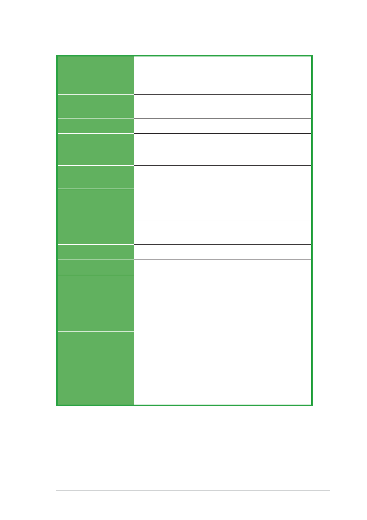
K8V-X specifications summary
CPU
Chipset
System Bus
Memory
Expansion slots
Storage
Audio
Socket 754 for AMD Athlon™ 64 processor with built-in 1MB
L2 cache
AMD 64 architecture that enables simultaneous 32-bit and
64-bit computing
VIA K8T800
VIA VT8237
800 MHz
3 x 184-pin DDR DIMM sockets for up to 3GB unbuffered
ECC and non-ECC PC3200/PC2700/PC2100
SDRAM memory
1 x AGP 8X/4X
5 x PCI
South Bridge supports
- 2 x UltraATA 133 connectors
- 2 x SATA with RAID 0, RAID 1
ADI AD1980 SoundMAX
support for S/PDIF out interface
®
6-channel audio Codec
LAN
USB
Overclocking
Features
Special features
Marvell® 88E8001 Gigabit LAN controller
Maximum of eight (8) USB 2.0 ports
Memory and VLink voltage adjustable
SFS (Stepless Frequency Selection) from 200 MHz up to
300 MHz at 1 MHz increment
Adjustable FSB/DDR ratio
ASUS JumperFree
ASUS C.P.R. (CPU Parameter Recall)
ASUS AI NET
ASUS C.P.R. (CPU Parameter Recall)
ASUS EZ Flash
ASUS CrashFree BIOS2
ASUS MyLogo2™
ASUS Instant Music Lite
Cool ‘n’ Quiet!™ Technology
Support S/PDIF out interface
(continued on the next page)
ix
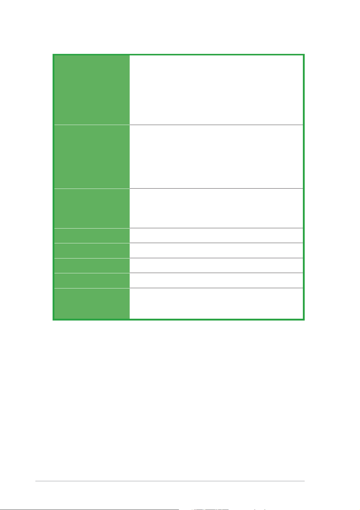
K8V-X specifications summary
Back panel I/O
Internal I/O
BIOS features
Industry standard
1 x Parallel port
1 x Serial port
1 x PS/2 keyboard port
1 x PS/2 mouse port
4 x USB 2.0 ports
1 x S/PDIF out
1 x RJ-45 port
Line In/Line Out/Microphone ports
2 x USB 2.0 connector for 4 additional USB ports
CPU/Chassis fan connectors
20-pin/4-pin ATX 12V power connectors
CD/AUX connectors
S/PDIF out connector
GAME/MIDI connector
Front panel audio connector
4Mb Flash EEPROM
AMI BIOS with enhanced ACPI, PnP, DMI, ASUS EZ Flash,
ASUS MyLogo2, SM BIOS 2.3, Multi-Language BIOS,
CrashFree BIOS 2
PCI 2.2, USB 2.0/1.1
Manageability
Power Requirement
Form Factor
Support CD contents
* Specifications are subject to change without notice.
WOL by PME, WOR by PME
ATX power supply (with 4-pin 12V plug)
ATX form factor: 12 in x 9.6 in (30.5 cm x 24.4 cm)
Device drivers
ASUS PC Probe
Anti-virus utility
x

Chapter 1
This chapter describes the features of the
motherboard. It includes brief descriptions of the
motherboard components, and illustrations of the
layout, jumper settings, and connectors.
Product introduction
1.1Welcome!
Thank you for buying the ASUS® K8V-X motherboard!
The motherboard delivers a host of new features and latest technologies making it
another standout in the long line of ASUS quality motherboards!
The motherboard combines the powers of the AMD Athlon™ 64 processor and the
VIA K8T800 chipset to set a new benchmark for an effective desktop platform
solution.
Supporting up to 3GB of system memory with PC3200/PC2700/PC2100/PC1600
DDR SDRAM, high-resolution graphics via an AGP 8X slot, Serial ATA RAID, USB
2.0, and 6-channel audio features, the motherboard takes you ahead in the world
of power computing!
Before you start installing the motherboard, and hardware devices on it, check the
items in your package with the list below.
1.2Package contents
Check your motherboard package for the following items.
ASUS K8V-X motherboard
ASUS motherboard support CD
1 x Ultra DMA 133/100/66 cables
2 x Serial ATA cables
1 x IDE cable
1 x Floppy disk cable
I/O shield
Bag of extra jumper caps
User guide
If any of the above items is damaged or missing, contact your retailer.
1-2
Chapter 1: Product introduction
1.3 Special features
1.3.1 Product Highlights
Latest processor technology
The AMD Athlon™ 64 desktop processor is based on AMD’s 64-bit architecture,
which represents the landmark introduction of the industry’s first x86-64
technology. This processor provides a dramatic leap forward in compatibility,
performance, investment protection, and reduced total cost of ownership and
development.
HyperTransport™ Technology
HyperTransport™ Technology is a high-speed, low latency, point-to-point link
designed to increase the communication speed between integrated circuits in
computers, networking and telecommunicatons equipment up to 48 times faster
than other existing technologies.
Cool ‘n’ Quiet!™ Technology
The motherboard supports the AMD® Cool ‘n’ Quiet!™ Technology that dynamically
and automatically changes the CPU speed, voltage and amount of power
depending on the task the CPU performs.
Serial ATA solution
The motherboard supports two interfaces compliant to the Serial ATA (SATA)
specification, an evolutionary replacement of the Parallel ATA storage interface.
The Serial ATA specification allows for thinner, more flexible cables with lower pin
count, reduced voltage requirement, up to 150 MB/s data transfer rate.
Serial ATA RAID solution
The motherboard provides a high-performance Serial ATA RAID controller that
enhance hard disk performance and data backup protection without the cost of
additional RAID cards. The onboard VIA VT8237 RAID controller provides two
Serial ATA connectors for RAID 0 and RAID 1 functions.
AGP 8X support
AGP 8X (AGP 3.0) is the VGA interface specification that enables enhanced
graphics performance with maximum bandwidth speeds of up to 2.12 GB/s.
S/PDIF out
The motherboard’s S/PDIF out function turns your computer into a high-end
entertainment system with digital connectivity to powerful speaker systems.
ASUS K8V-X motherboard
1-3

USB 2.0 technology
The motherboard implements the new Universal Serial Bus (USB) 2.0
specification, extending the connection speed from 12 Mbps on USB 1.1 to a fast
480 Mbps on USB 2.0 - supporting up to eight USB 2.0 ports. The higher
bandwidth of USB 2.0 allows connection of devices such as high resolution video
conferencing cameras, next generation scanners and printers, and fast storage
units. USB 2.0 is backward compatible with USB 1.1.
6-Channel Audio solution
The motherboard uses an onboard audio CODEC that lets you enjoy high-quality
6-channel audio without having to buy advanced sound cards.
1.3.2 Unique ASUS features
AI NET solution
The Marvell® 88E8001 Gigabit PCI LAN controller chipset is onboard to provide a
single-chip solution for LAN on Motherboard (LOM) applications. The controller
integrates 32-bit 10/100/1000BASE-T Gigabit Ethernet Media Access Control
(IEEE 802.3 compliant) and Physical Layer Transceiver solution to support high
performance network applications. The controller is equipped with the
net-diagnosing utility VCT (Virtual Cable Tester), that intelligently diagnoses and
reports cable faults from a remote location up to 100 meters. This feature helps
maintain a more stable network connection.
CrashFree BIOS 2
This feature allows you to restore the original BIOS data from the ASUS support
CD in case when the BIOS codes and data are corrupted. This protection
eliminates the need to buy a replacement ROM chip. See page 2-6.
C.P.R. (CPU Parameter Recall)
The C.P.R. feature of the motherboard BIOS allows automatic re-setting to the
BIOS default settings in case the system hangs due to overclocking. When the
system hangs due to overclocking, C.P.R. eliminates the need to open the system
chassis and clear the RTC data. Simply shut down and reboot the system, and
BIOS automatically restores the CPU previous setting for each parameter.
ASUS MyLogo2™
This new feature present in the motherboard allows you to personalize and add
style to your system with customizable boot logos. See pages 2-31.
1-4
Chapter 1: Product introduction
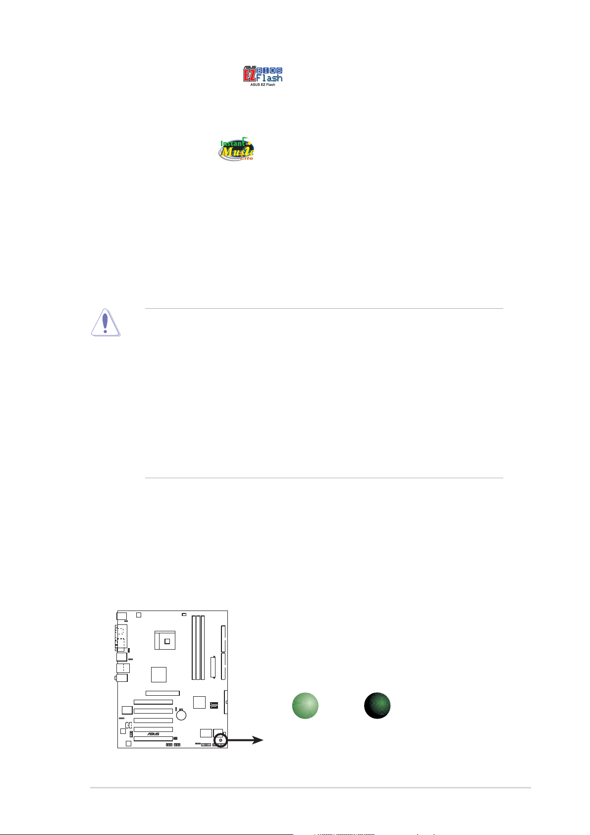
ASUS EZ Flash BIOS
With the ASUS EZ Flash, you can easily update the system BIOS even before
loading the operating system. No need to use a DOS-based utility or boot from a
floppy disk. See page 2-5.
Instant Music Lite
This unique feature allows you to playback audio CDs even without booting the
system to Windows®. Just press the ASUS Instant Music special function keys and
enjoy the music! See details on pages 2-25 and 3-6.
1.4 Before you proceed
Take note of the following precautions before you install motherboard components
or change any motherboard settings.
1. Unplug the power cord from the wall socket before touching any
component.
2. Use a grounded wrist strap or touch a safely grounded object or to a metal
object, such as the power supply case, before handling components to
avoid damaging them due to static electricity.
3. Hold components by the edges to avoid touching the ICs on them.
4. Whenever you uninstall any component, place it on a grounded antistatic
pad or in the bag that came with the component.
5. Before you install or remove any component, ensure that the ATX
power supply is switched off or the power cord is detached from the
power supply. Failure to do so may cause severe damage to the
motherboard, peripherals, and/or components.
Onboard LED
The motherboard comes with a stand-by power LED. When lit, this green LED
indicates that the system is ON, in sleep mode, or in soft-off mode, a reminder that
you should shut down the system and unplug the power cable before removing or
plugging in any motherboard component. The illustration below shows the location
of the onboard LED.
SB_PWR
K8V-X
®
K8V-X Onboard LED
ON
Standby
Power
OFF
Powered
Off
ASUS K8V-X motherboard
1-5
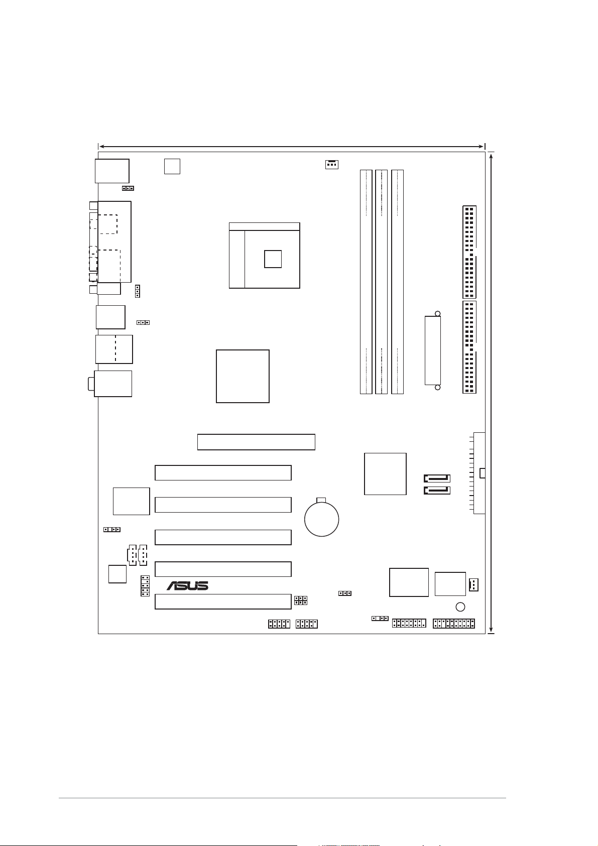
1.5 Motherboard overview
1.5.1 Motherboard layout
24.5cm (9.6in)
PS/2KBMS
T: Mouse
B: Keyboard
KBPWR
SPDIF_O
COM1
F_USB12
Bottom:
Top:
USB3
RJ-45
USB4
Top:Line In
Center:Line Out
Below:Mic In
ATX12V
PARALLEL PORT
Socket 754
USBPWR12
USBPWR34
VIA
K8T800
CPU_FAN
PRI_IDESEC_IDE
DDR DIMM2 (64 bit,184-pin module)
DDR DIMM1 (64 bit,184-pin module)
DDR DIMM3 (64 bit,184-pin module)
ATX Power Connector
Marvell
Gigabit
LAN
SPDIF_OUT
CD
ADI
AD1980
FP_AUDIO
AUX
Accelerated Graphics Port (AGP)
PCI1
PCI2
PCI3
PCI4
®
K8V-X
USBPWR56
USBPWR78
PCI5
USB56
USB78
CR2032 3V
Lithium Cell
CMOS Power
CLRTC
VIA
VT8237
CHASSIS
Super
I/O
GAME
SATA2
SATA1
SB_PWR
4Mbit
BIOS
30.5cm (12.0in)
FLOPPY
CHA_FAN
PANEL
1-6
Chapter 1: Product introduction
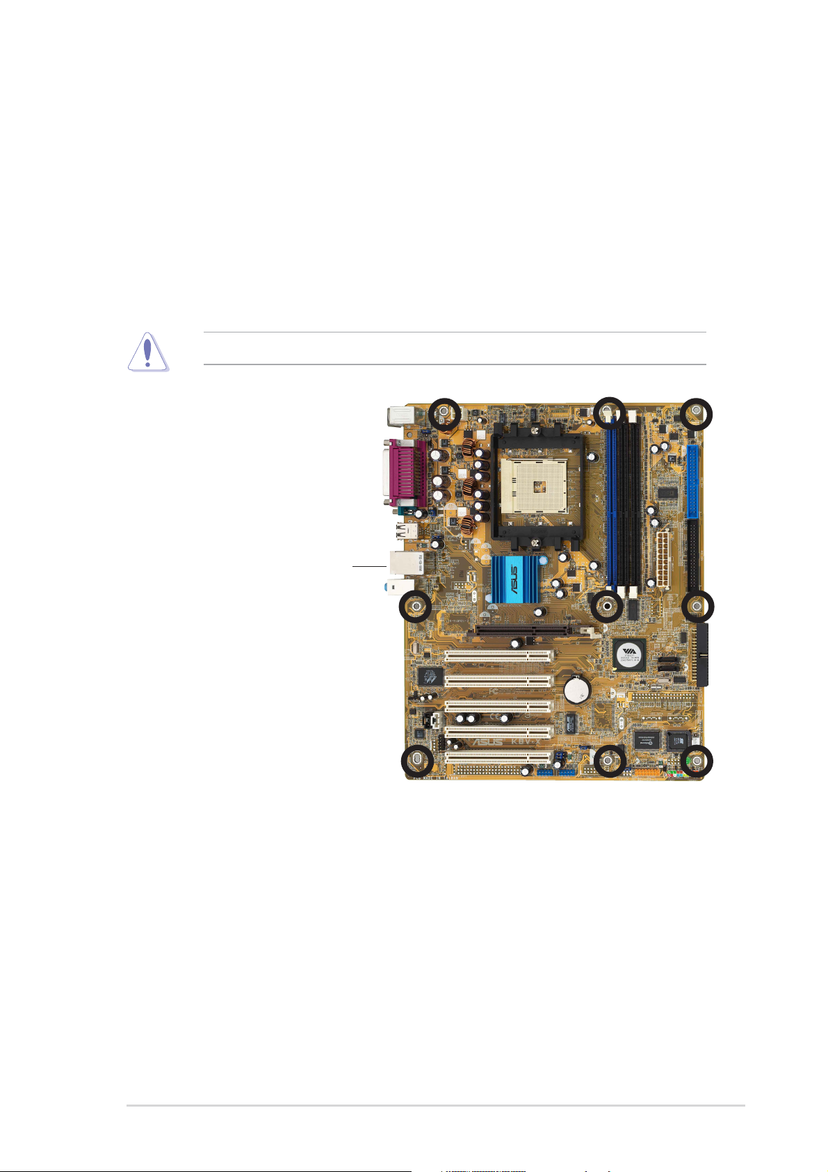
1.5.2 Placement direction
When installing the motherboard, make sure that you place it into the chassis in
the correct orientation. The edge with external ports goes to the rear part of the
chassis as indicated in the image below.
1.5.3 Screw holes
Place nine (9) screws into the holes indicated by circles to secure the motherboard
to the chassis.
Do not overtighten the screws! Doing so may damage the motherboard.
Place this side towards
the rear of the chassis
ASUS K8V-X motherboard
1-7
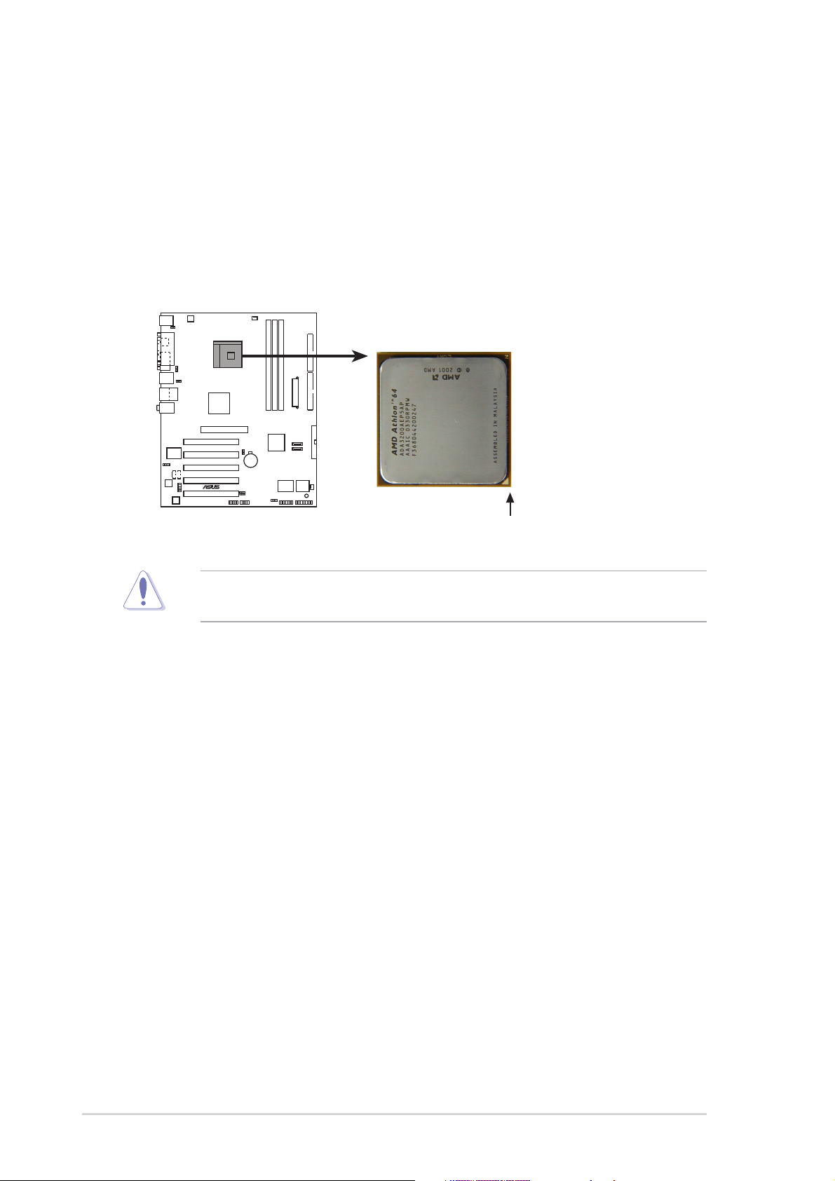
1.6 Central Processing Unit (CPU)
1.6.1 Overview
The motherboard comes with a surface mount 754-pin Zero Insertion Force (ZIF)
socket designed for the AMD Athlon™ 64 processor.
The 128-bit-wide data paths of these processors can run applications faster than
processors with only 32-bit or 64-bit wide data paths.
K8V-X
®
K8V-X Socket 754
Incorrect installation of the CPU into the socket may bend the pins and severely
damage the CPU!
Gold Arrow
1-8
Chapter 1: Product introduction
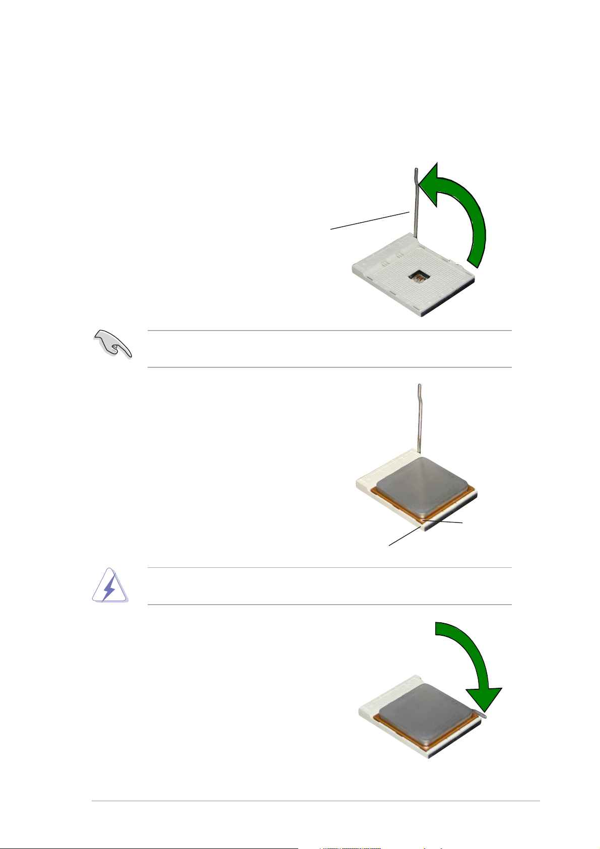
1.6.2 Installing the CPU
Follow these steps to install a CPU.
1. Locate the 754-pin ZIF socket on the motherboard.
2. Unlock the socket by pressing the
lever sideways, then lift it up to a
90°-100° angle.
Socket Lever
Make sure that the socket lever is lifted up to 90°-100° angle, otherwise the
CPU does not fit in completely.
3. Position the CPU above the socket
such that the CPU corner with the
gold triangle matches the socket
corner with a small triangle.
4. Carefully insert the CPU into the
socket until it fits in place.
The CPU fits only in one correct orientation. DO NOT force the CPU into the
socket to prevent bending the pins and damaging the CPU!
5. When the CPU is in place, push
down the socket lever to secure the
CPU. The lever clicks on the side tab
to indicate that it is locked.
Gold triangle
Small triangle
6. Install specifically designed heatsink
and fan assembly.
ASUS K8V-X motherboard
1-9
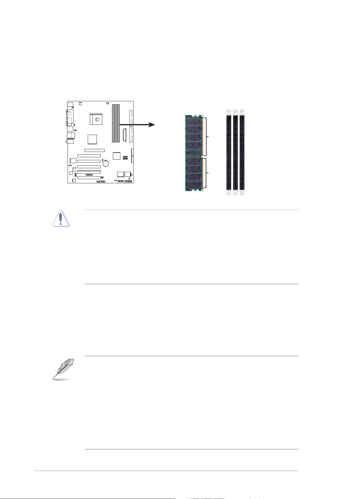
1.7System memory
1.7.1 DIMM sockets location
The following figure illustrates the location of the DDR DIMM sockets.
DIMM1
DIMM2
DIMM3
K8V-X
®
80 Pins 104 Pins
K8V-X 184-Pin DDR DIMM Sockets
• It is recommended to use the blue DIMM slots first.
• Make sure to unplug the power supply before adding or removing DIMMs or
other system components. Failure to do so may cause severe damage to
both the motherboard and the components.
• When installing long AGP cards, it is recommended to install the memory
modules first. Long AGP cards, when installed, may interfere with the
memory sockets.
1.7.2 Memory configurations
You may install 64MB, 128MB, 256MB, 512MB, and 1GB DDR DIMMs into the
DIMM sockets using the memory configurations in this section.
Important notes
• Installing DDR DIMMs other than the recommended configurations may
cause memory sizing error or system boot failure. Use any of the
recommended configurations in Table 1.
• For optimum compatibility, obtain memory modules from qualified vendors.
See Qualified Vendors List on page 1-12.
• Use the blue DIMM slot first.
• Stacked RAM and DDR DIMM modules with more than 18 chips are not
supported.
• Always install DIMMs with the same CAS Latency. For optimum
compatibility, obtain memory modules from the same vendors. See
Qualified Vendors List on page 1-12.
1-10
Chapter 1: Product introduction
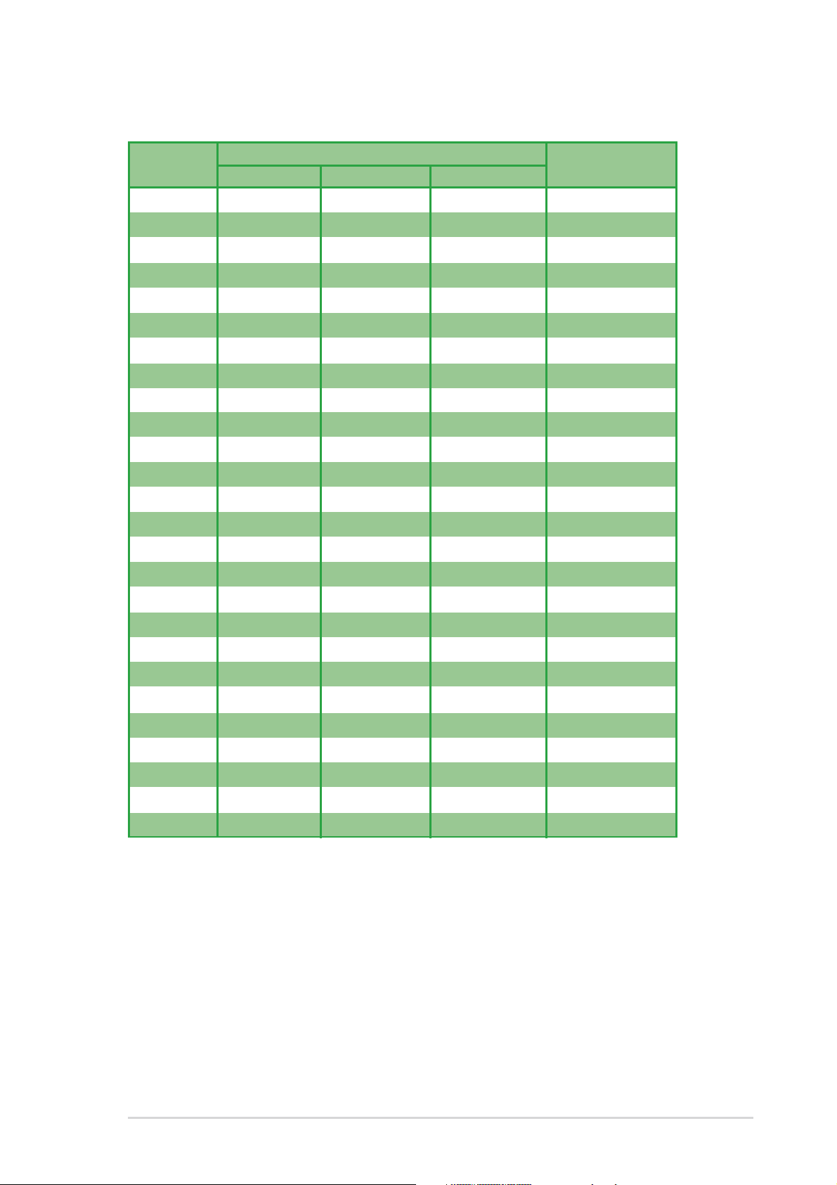
Table 1 Recommended memory configurations
Number of DIMM Slot
DIMMs DIMM1 DIMM2 DIMM3 Max Speed
1 Single Side - - DDR 400
1-Single Side - DDR 400
1- -Single Side DDR 400
1 Double Side - - DDR 400
1-Double Side - DDR 400
1- -Double Side DDR 400
2 Single Side Single Side - DDR 400
2 Single Side Double Side - DDR 400
2 Single Side - Single Side DDR 400
2 Single Side - Double Side DDR 400
2 Double Side Single Side - DDR 400
2 Double Side Double Side - DDR 333
2 Double Side - Single Side DDR 400
2-Single Side Single Side DDR 400
2-Single Side Double Side DDR 400
2-Double Side Single Side DDR 400
2-Double Side Double Side DDR 333
2 Double Side - Double Side DDR 333
3 Single Side Single Side Single Side DDR 400
3 Single Side Single Side Double Side DDR 333
3 Single Side Double Side Single Side DDR 333
3 Single Side Double Side Double Side DDR 333
3 Double Side Single Side Single Side DDR 333
3 Double Side Single Side Double Side DDR 333
3 Double Side Double Side Single Side DDR 333
3 Double Side Double Side Double Side DDR 333
ASUS K8V-X motherboard
1-11
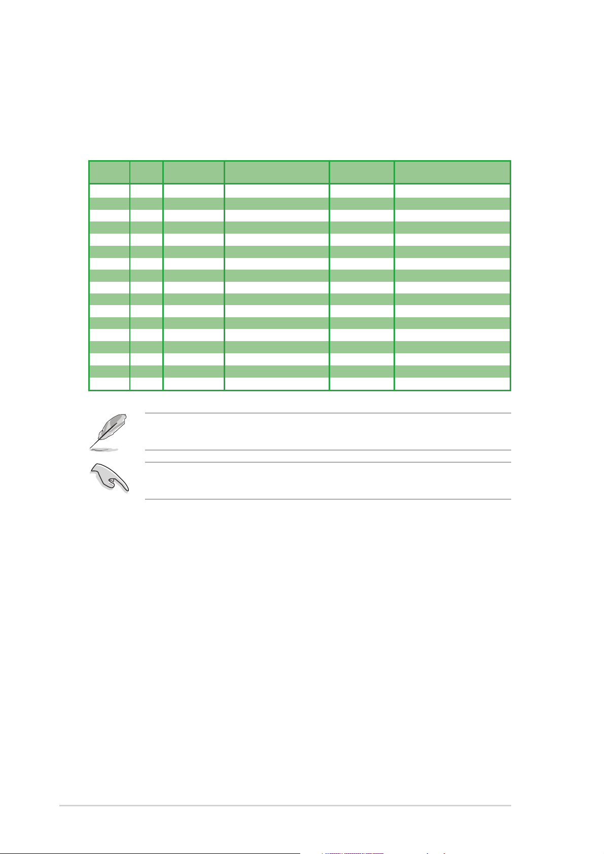
DDR Qualified Vendor List
The following table lists the PC3200 (DDR400) memory modules that have been
tested and qualified for use with this motherboard.
Table 2 DDR400 Qualified Vendor List (QVL)
Size SS/DS Vendor Chip Number Chip Brand Part Number
256MB SS KINGSTON HY5DU56822BT-D43 Hynix KVR400X64C3A/256
512MB DS KINGSTON HY5DU56822BT-D43 Hynix KVR400X64C3A/512
256MB SS KINGSTON HYB25D256800BT-5B Infineon KVR400X64C3A/256
512MB DS KINGSTON HYB25D256809BT-5B Infineon KVR400X64C3A/512
512MB DS KINGSTON D328DIB-50 KINGSTON KVR400X64C3A/512
512MB DS KINGSTON Heat-Sink Package N/A KHX3200A/512
512MB DS SAMSUNG K4H560838E-TCCC SAMSUNG M368L6423ETM-CCC
256MB SS SAMSUNG K4H560838F-TCCC SAMSUNG M368L3223FTN-CCC
256MB DS SAMSUNG K4H560838F-TCCC SAMSUNG M368L6423FTN-CCC
256MB SS Hynix HY5DU56822BT-D43 Hynix HYMD232646B8J-D43 AA
512MB DS Hynix HY5DU56822BT-D43 Hynix HYMD264646B8J-D43 AA
256MB SS MICRON MT46V32M8TG-5BC MICRON MT8VDDT3264AG-40BCB
512MB DS MICRON MT46V32M8TG-5BC MICRON MT16VDDT6464AG-40BCB
256MB SS Infineon HYB25D256800BT-5B Infineon HYS64D32300GU-5-B
512MB DS Infineon HYB25D256800BT-5B Infineon HYS64D64320GU-5-B
256MB SS Infineon HYB25D256800CE-5C Infineon HYS64D32300HU-5-C
512MB DS CORSAIR Heat-Sink Package Winbond CMX512-3200C2
Visit the ASUS website (www.asus.com) for the latest DDR 400 Qualified
Vendor List for this motherboard.
Obtain DDR DIMMs only from ASUS qualified vendors for better system
performance.
1-12
Chapter 1: Product introduction
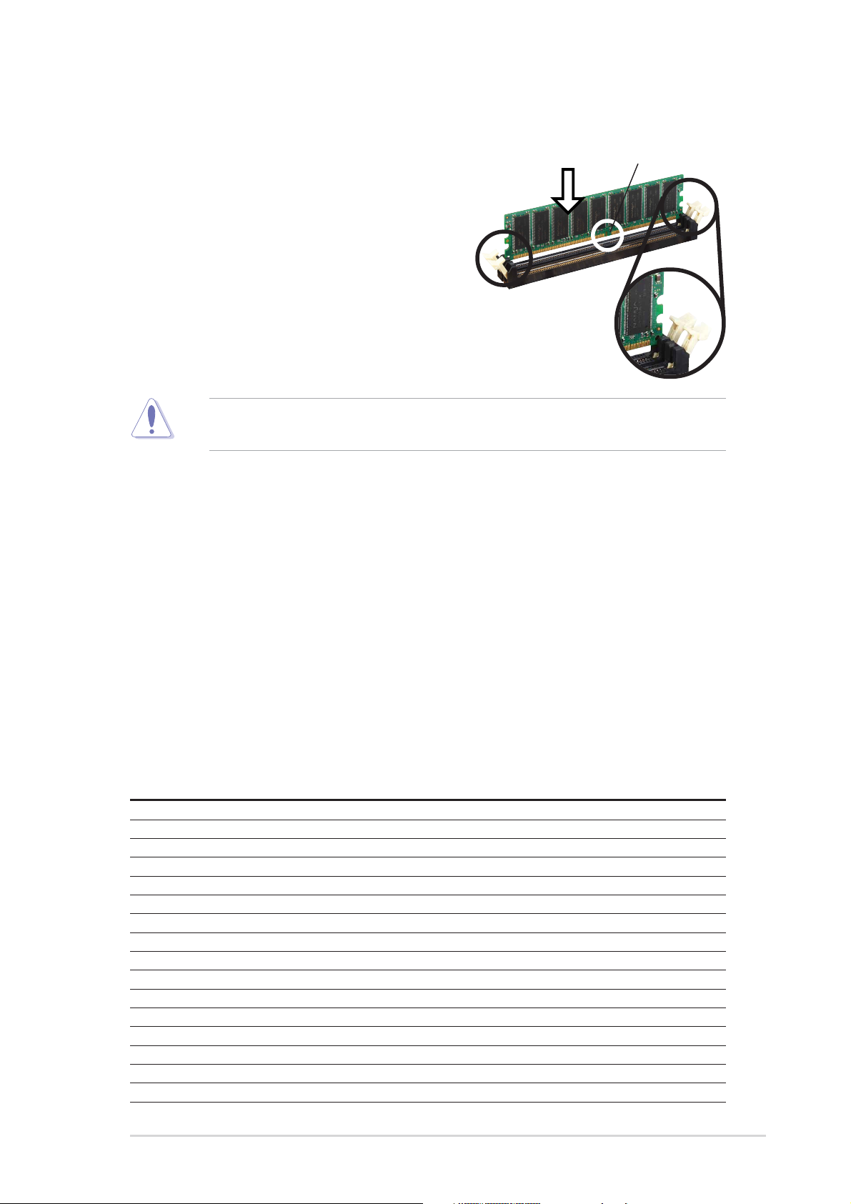
1.7.3 Installing a DIMM
Follow these steps to install a DIMM.
1. Unlock a DIMM socket by pressing the
retaining clips outward.
2. Align a DIMM on the socket such that the
notch on the DIMM matches the break on
the socket.
3. Firmly insert the DIMM into the socket
until the retaining clips snap back in place
and the DIMM is properly seated.
A DDR DIMM is keyed with a notch so that it fits in only one direction. DO NOT
force a DIMM into a socket to avoid damaging the DIMM.
1.8 Expansion slots
To install and configure an expansion card:
DDR DIMM
Unlocked
1. Install an expansion card following the instructions that came with the chassis.
2. Turn on the system and change the necessary BIOS settings, if any. See
Chapter 2 for BIOS information.
3. Assign an IRQ to the card. Refer to the tables next page.
4. Install the drivers and/or software applications for the expansion card
according to the card documentation.
1.8.1 Standard interrupt assignments
IRQ Priority Standard Function
0 1 System Timer
1 2 Keyboard Controller
2 N/A Programmable Interrupt
3* 11 IRQ holder for PCI steering
4* 12 Communications Port (COM1)
5* 13 IRQ holder for PCI steering
6 14 Floppy Disk Controller
7* 15 Printer Port (LPT1)
8 3 System CMOS/Real Time Clock
9* 4 IRQ holder for PCI steering
10* 5 IRQ holder for PCI steering
11*6 IRQ holder for PCI steering
12* 7 PS/2 Compatible Mouse Port
13 8 Numeric Data Processor
14* 9 Primary IDE Channel
15* 10 Secondary IDE Channel
* These IRQs are usually available for ISA or PCI devices.
ASUS K8V-X motherboard
1-13
1.8.2 IRQ assignments for this motherboard
INT A INT B INT C INT D
PCI slot 1 shared — — —
PCI slot 2 — shared — —
PCI slot 3 — — shared —
PCI slot 4 — — — used
PCI slot 5 shared — — —
Gigabit LAN — shared — —
AGP slot shared — — —
When using PCI cards on shared slots, ensure that the drivers support “Share
IRQ” or that the cards do not need IRQ assignments. Otherwise, conflicts will
arise between the two PCI groups, making the system unstable and the card
inoperable.
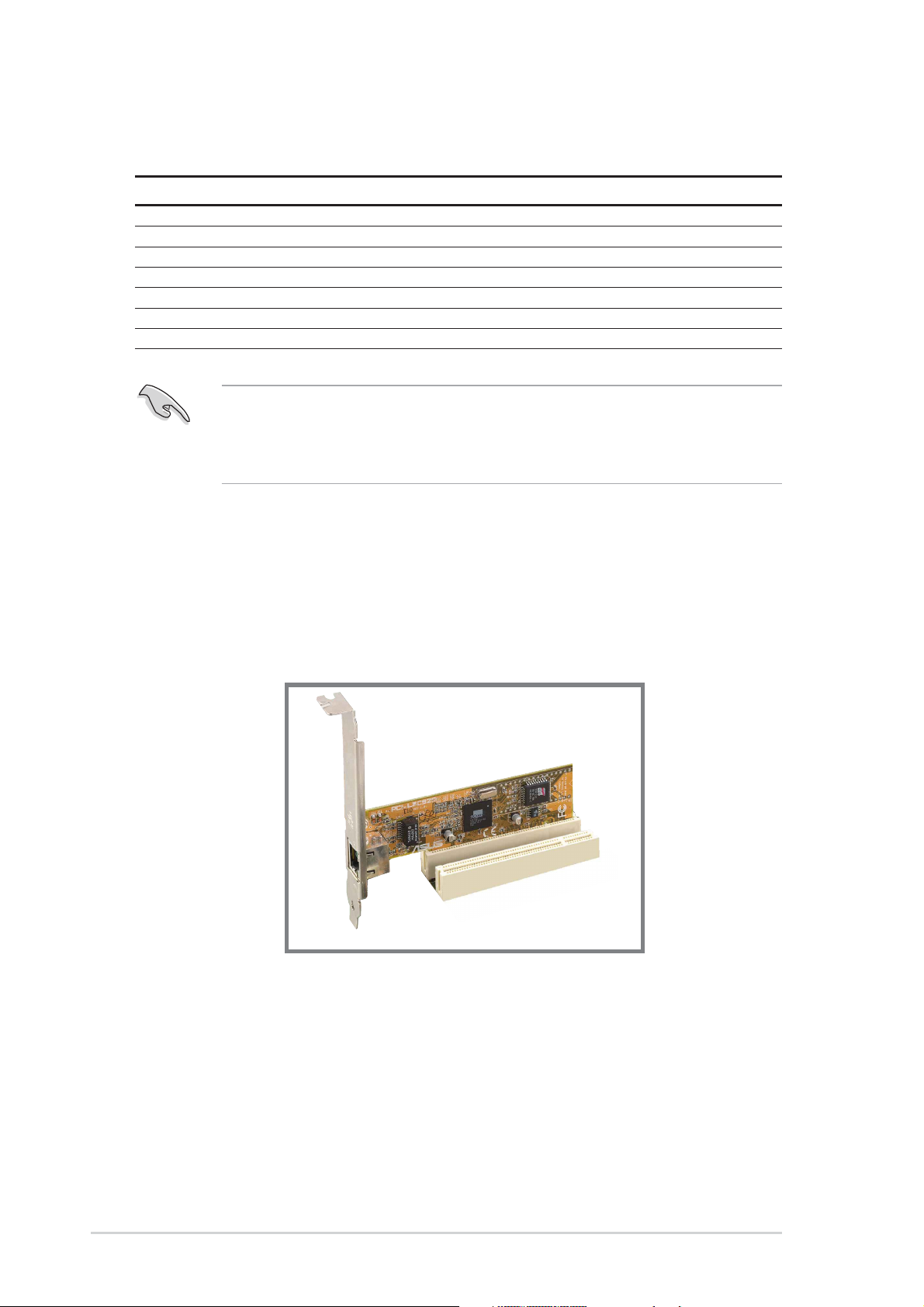
1.8.3 PCI slots
The PCI slots support PCI cards such as a LAN card, SCSI card, USB card, and
other cards that comply with PCI specifications.
1-14
Chapter 1: Product introduction
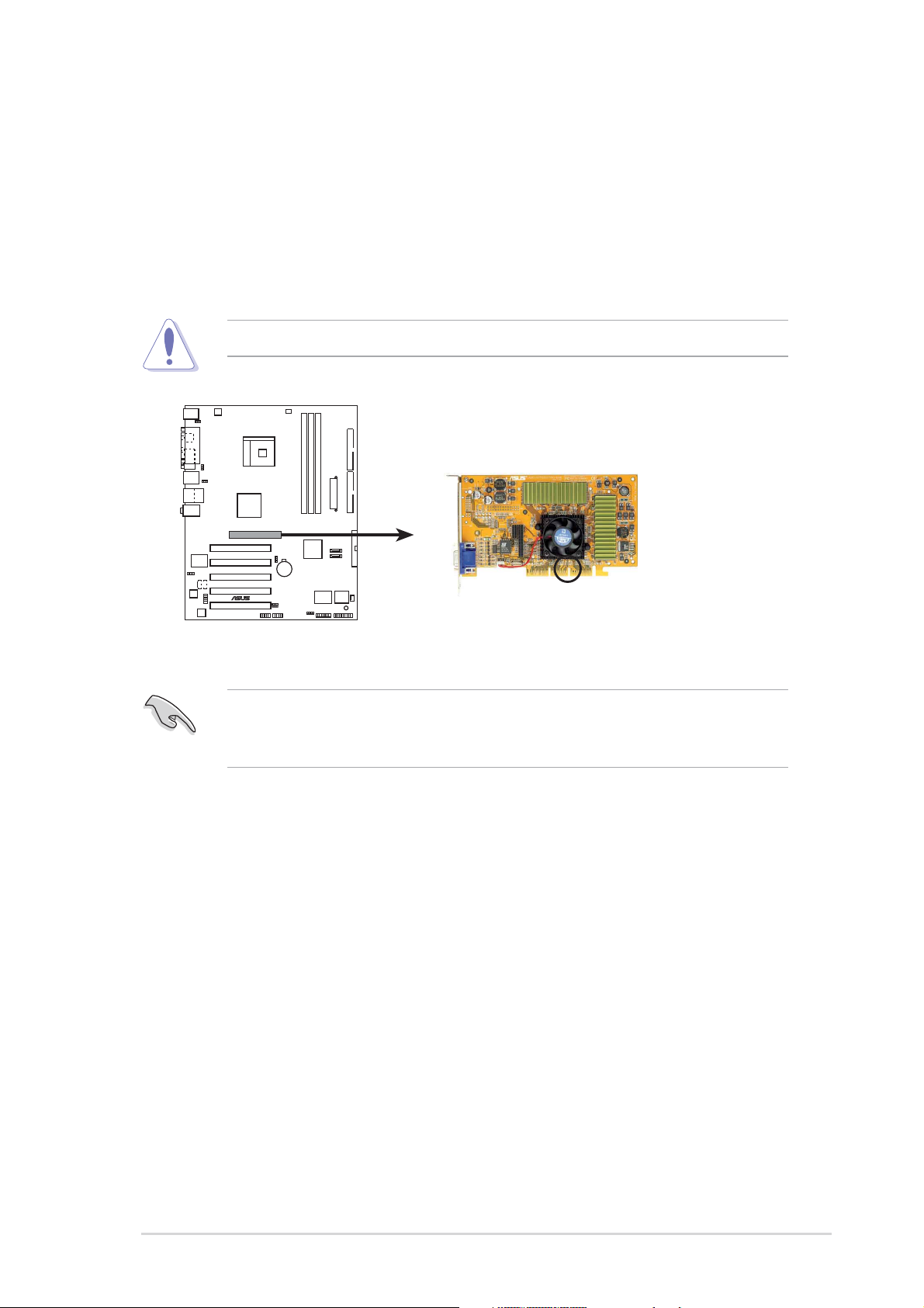
1.8.4 AGP slot
The Accelerated Graphics Port (AGP) slot supports AGP 8X/4X (+1.5V) cards.
When you buy an AGP card, make sure that you ask for one with +1.5V
specification.
Note the notches on the card golden fingers to ensure that they fit the AGP slot on
the motherboard.
Install only +1.5V AGP cards.
K8V-X
®
K8V-X Accelerated Graphics Port (AGP)
If installing the ATi 9500 or 9700 Pro Series VGA cards, use only the card
version PN xxx-xxxxx-30 or later, for optimum performance and overclocking
stability.
Keyed for 1.5v
ASUS K8V-X motherboard
1-15
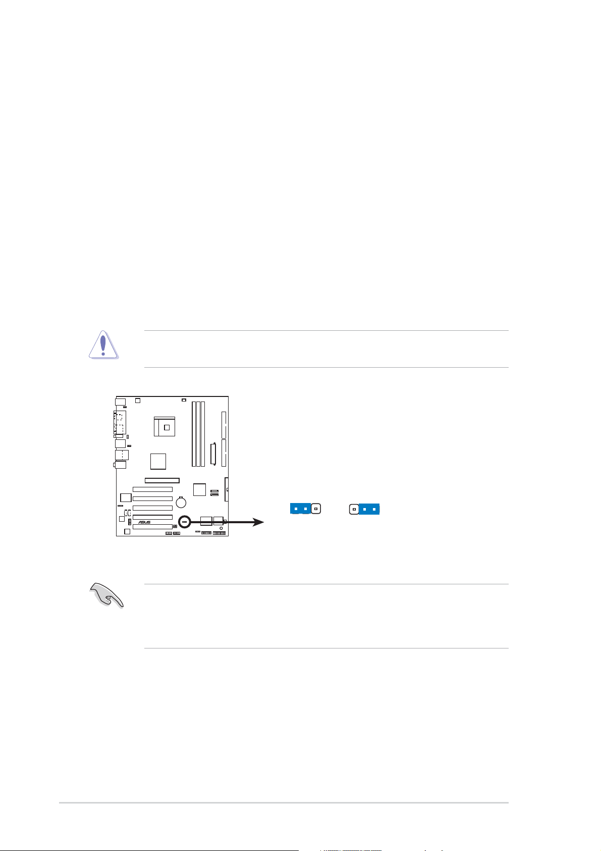
1.9 Jumpers
1. Clear RTC RAM (CLRTC)
This jumper allows you to clear the Real Time Clock (RTC) RAM in CMOS.
You can clear the CMOS memory of date, time, and system setup parameters
by erasing the CMOS RTC RAM data. The RAM data in CMOS, that include
system setup information such as system passwords, is powered by the
onboard button cell battery.
To erase the RTC RAM:
1. Turn OFF the computer and unplug the power cord.
2. Move the jumper cap from pins 1-2 (default) to pins 2-3. Keep the cap on
pins 2-3 for about 5~10 seconds, then move the cap back to pins 1-2.
3. Plug the power cord and turn ON the computer.
4. Hold down the <Del> key during the boot process and enter BIOS setup to
re-enter data.
Except when clearing the RTC RAM, never remove the cap on the jumper
default position. Removing the cap will cause system boot failure!
®
K8V-X
K8V-X Clear RTC RAM
You do not need to clear the RTC when the system hangs due to overclocking.
For system failure due to overclocking, use the C.P.R. (CPU Parameter Recall)
feature. Shut down and reboot the system so BIOS can automatically reset
parameter settings to its previous values.
CLRTC
12 23
Normal Clear CMOS
(Default)
1-16
Chapter 1: Product introduction
 Loading...