

Page 1

K8V-MX
User Guide
Motherboard
Page 2

E2125
First Edition V1.00
July 2005
Copyright © 2005 ASUSTeK COMPUTER INC. All Rights Reserved.
No part of this manual, including the products and software described in it, may be reproduced,
transmitted, transcribed, stored in a retrieval system, or translated into any language in any
form or by any means, except documentation kept by the purchaser for backup purposes,
without the express written permission of ASUSTeK COMPUTER INC. (“ASUS”).
Product warranty or service will not be extended if: (1) the product is repaired, modified or
altered, unless such repair, modification of alteration is authorized in writing by ASUS; or (2)
the serial number of the product is defaced or missing.
ASUS PROVIDES THIS MANUAL “AS IS” WITHOUT WARRANTY OF ANY KIND, EITHER
EXPRESS OR IMPLIED, INCLUDING BUT NOT LIMITED TO THE IMPLIED WARRANTIES
OR CONDITIONS OF MERCHANTABILITY OR FITNESS FOR A PARTICULAR PURPOSE.
IN NO EVENT SHALL ASUS, ITS DIRECTORS, OFFICERS, EMPLOYEES OR AGENTS BE
LIABLE FOR ANY INDIRECT, SPECIAL, INCIDENTAL, OR CONSEQUENTIAL DAMAGES
(INCLUDING DAMAGES FOR LOSS OF PROFITS, LOSS OF BUSINESS, LOSS OF USE
OR DATA, INTERRUPTION OF BUSINESS AND THE LIKE), EVEN IF ASUS HAS BEEN
ADVISED OF THE POSSIBILITY OF SUCH DAMAGES ARISING FROM ANY DEFECT OR
ERROR IN THIS MANUAL OR PRODUCT.
SPECIFICATIONS AND INFORMATION CONTAINED IN THIS MANUAL ARE FURNISHED
FOR INFORMATIONAL USE ONLY, AND ARE SUBJECT TO CHANGE AT ANY TIME
WI TH OU T NO TI CE , AND SH OU LD NOT BE CO NS TR UE D AS A COMMITMENT BY
ASUS. ASUS ASSUMES NO RESPONSIBILITY OR LIABILITY FOR ANY ERRORS OR
INACCURACIES THAT MAY APPEAR IN THIS MANUAL, INCLUDING THE PRODUCTS
AND SOFTWARE DESCRIBED IN IT.
Products and corporate names appearing in this manual may or may not be registered
trademarks or copyrights of their respective companies, and are used only for identification or
explanation and to the ownersʼ benefit, without intent to infringe.
ii
Page 3

Contents
Notices ............................................................................................ vi
Safety information .......................................................................... vii
About this guide .............................................................................viii
K8V-MX specifications summary .................................................... ix
Chapter 1: Product Introduction
1.1 Welcome! .............................................................................1-2
1.2 Package contents ................................................................1-2
1.3 Special features ...................................................................1-2
1.3.1 Product highlights ....................................................1-2
1.3.2 ASUS unique features .............................................1-4
1.4 Before you proceed .............................................................1-5
1.5 Motherboard overview .........................................................1-6
1.5.1 Motherboard layout .................................................1-6
1.5.2 Placement direction .................................................1-7
1.5.3 Screw holes .............................................................1-7
1.6 Central Processing Unit (CPU) ............................................1-8
1.6.1 Overview .................................................................1-8
1.6.2 Installing the CPU ...................................................1-8
1.7 System memory .................................................................1-10
1.7.1 Overview ...............................................................1-10
1.7.2 Memory configurations ..........................................1-10
1.7.3 Installing a DIMM ...................................................1-13
1.7.4 Removing a DIMM .................................................1-13
1.8 Expansion slots ..................................................................1-14
1.8.1 Installing an expansion card ..................................1-14
1.8.2 Configuring an expansion card .............................1-14
1.8.3 PCI slots ................................................................1-16
1.8.4 AGP slot ................................................................1-16
1.9 Jumpers .............................................................................1-17
1.10 Connectors ........................................................................1-19
1.10.1 Rear panel connectors ..........................................1-19
1.10.2 Internal connectors ................................................1-21
iii
Page 4

Contents
Chapter 2: BIOS Information
2.1 Managing and updating your BIOS ......................................2-2
2.1.1 Creating a bootable floppy disk ...............................2-2
2.1.2 Using AFUDOS to copy the current BIOS ...............2-2
2.1.3 Using AFUDOS to update the BIOS ........................2-3
2.1.4 Using ASUS EZ Flash to update the BIOS .............2-5
2.2 BIOS Setup program ...........................................................2-6
2.2.1 BIOS menu screen ..................................................2-7
2.2.2 Menu bar .................................................................2-7
2.2.3 Navigation keys .......................................................2-7
2.2.4 Menu items ..............................................................2-8
2.2.5 Sub-menu items ......................................................2-8
2.2.6 Configuration fields .................................................2-8
2.2.7 Pop-up window ........................................................2-8
2.2.8 Scroll bar .................................................................2-8
2.2.9 General help ............................................................2-8
2.3 Main menu ...........................................................................2-9
2.3.1 System Time ...........................................................2-9
2.3.2 System Date ...........................................................2-9
2.3.3 Legacy Diskette A ....................................................2-9
2.3.4 Diskette Write .........................................................2-9
2.3.5 Primary/Secondary IDE Master/Slave ...................2-10
2.3.6 System Information ...............................................2-11
2.4 Advanced menu .................................................................2-12
2.4.1 CPU Configuration ................................................2-12
2.4.2 Chipset ..................................................................2-15
2.4.3 Onboard Devices Configuration ............................2-19
2.4.4 PCI PnP .................................................................2-21
2.4.5 System Frequency/Voltage Configuration .............2-22
2.5 Power menu .......................................................................2-23
2.5.1 Suspend Mode .....................................................2-23
2.5.2 Repost Video on S3 Resume ...............................2-23
2.5.3 ACPI 2.0 Support ..................................................2-23
2.5.4 ACPI APIC Support ...............................................2-23
2.5.5 APM Configuration ................................................2-24
2.5.6 Hardware Monitor ..................................................2-26
2.6 Boot menu .........................................................................2-27
2.6.1 Boot Device Priority ...............................................2-28
2.6.2 Boot Settings Configuration ..................................2-29
2.6.3 Security .................................................................2-30
2.7 Exit menu ...........................................................................2-31
iv
Page 5

Contents
Chapter 3: Software Support
3.1 Installing an operating system .............................................3-2
3.2 Support CD information .......................................................3-2
3.2.1 Running the support CD ..........................................3-2
3.2.2 Drivers menu ...........................................................3-3
3.2.3 Utilities menu ...........................................................3-3
3.2.4 Contacts menu ........................................................3-4
v
Page 6

Notices
Federal Communications Commission Statement
This device complies with Part 15 of the FCC Rules. Operation is subject
to the following two conditions:
• This device may not cause harmful interference, and
• This d e v i ce must accept a n y interferen c e received i n c l u ding
interference that may cause undesired operation.
This equipment has been tested and found to comply with the limits for a
Class B digital device, pursuant to Part 15 of the FCC Rules. These limits
are designed to provide reasonable protection against harmful interference
in a residential installation. This equipment generates, uses and can
radiate radio frequency energy and, if not installed and used in accordance
with manufacturerʼs instructions, may cause harmful interference to radio
communications. However, there is no guarantee that interference will
not occur in a particular installation. If this equipment does cause harmful
interference to radio or television reception, which can be determined by
turning the equipment off and on, the user is encouraged to try to correct
the interference by one or more of the following measures:
• Reorient or relocate the receiving antenna.
• Increase the separation between the equipment and receiver.
• Connect the equipment to an outlet on a circuit different from that to
which the receiver is connected.
• Consult the dealer or an experienced radio/TV technician for help.
To assure compliance with FCC regulations, use shielded cables to
connect the monitor to the graphics card. Changes to this unit not
expressly approved by the party responsible for compliance can void
the userʼs authority to operate this equipment.
Canadian Department of Communications Statement
This digital app aratus does not exceed the Class B limits for radio
noise emissions from digital apparatus set out in the Radio Interference
Regulations of the Canadian Department of Communications.
This class B digital apparatus complies with Canadian ICES-003.
vi
Page 7

Safety Information
Electrical safety
• To prevent electrical shock hazard, disconnect the power cable from
the electrical outlet before relocating the system.
• When adding or removing devices to or from the system, ensure that
the power cables for the devices are unplugged before the signal
cables are connected. If possible, disconnect all power cables from the
existing system before you add a device.
• Before connecting or removing signal cables from the motherboard,
ensure that all power cables are unplugged.
• Seek professional assistance before using an adapter or extension
cord. These devices can interrupt the grounding circuit.
• Set your power supply to the correct voltage in your area. If you are
not sure about the voltage of the electrical outlet you are using, contact
your local power company.
• If the power supply is broken, do not try to fix it by yourself. Contact a
qualified service technician or your retailer.
Operational safety
• Before installing the motherboard and adding devices on it, carefully
read all the manuals that came with the package.
• Before using the product, make sure all cables are correctly connected
and the power cables are not damaged. If you detect any damage,
contact your dealer immediately.
• To avoid short circuits, keep paper clips, screws, and staples away
from connectors, slots, sockets, and circuitry.
• Avoid dust, humidity, and temperature extremes. Do not place the
product in any area where it can get wet.
• Place the product on a stable surface.
• If you encounter technical problems with the product, contact a
qualified service technician or your retailer.
vii
Page 8

About This Guide
Conventions used in this guide
To make sure that you perform certain tasks properly, take note of the
following symbols used throughout this guide.
WARNING:
complete a task.
CAUTION:
when trying to complete a task.
IMPORTANT:
NOTE:
Information to prevent injury to yourself when trying to
Information to prevent damage to the components
Instructions that you MUST follow to complete a task.
Tips and additional information to help you complete a task.
Where to find more information
Refer to the following sources for additional information and for product
and software updates.
1. ASUS websites
The ASUS websites worldwide provide updated information on ASUS
hardware and software products. Refer to the ASUS contact information.
2. Optional documentation
Your product package may include optional documentation, such as
warranty flyers, that may have been added by your dealer. These
documents are not part of the standard package.
viii
Page 9

K8V-MX Specifications Summary
CPU
Chipset
System bus
Memory
Expansion slots
VGA
Storage
Audio
LAN
USB 2.0
Rear panel I/O ports
Socket 754 for AMD Athlon™ 64 processor with 800 MHz
FSB frequency and built-in L2 cache up to 1 MB
AMD Athlon™ 64 architecture supports simultaneous 32-bit
and 64-bit computing
VIA K8M800
VIA VT8237R
1600MT/s
2 x 184-pin DDR DIMM sockets for up to 2 GB unbuffered
ECC, non-ECC DDR 400/333/266 DRAM memory
1 x AGP8X
3 x PCI
Integrated Graphics
2 x Serial ATA, RAID 0, RAID 1, JBOD
2 x UltraDMA 133/100/66
ADI AD1888 SoundMAX 6-channel audio CODEC
S/PDIF out interface
Integrated 10/100 Mbps LAN controller in the southbridge
with Realtek RTL8201CL LAN PHY
Supports up to 8 USB 2.0 ports
1 x Parallel port
1 x Serial port
1 x PS/2 keyboard port
1 x PS/2 mouse port
1 x VGA port
1 x Audio I/O port
1 x LAN (RJ-45) port
4 x USB 2.0 ports
(Continued on the next page)
ix
Page 10

K8V-MX Specifications Summary
Internal I/O connectors
BIOS features
Industry standard
ASUS Special features
Manageability
Support CD
Accessary
Form factor
2 x USB connectors supports additional 4 USB ports
20-pin ATX power connector
4-pin ATX 12V power connector
CD/AUX audio in
Chassis Intrusion
CPU/chassis fan connectors
Front panel audio connector
S/PDIF out connector
4Mb Flash ROM, AMI BIOS, (TCAV), PnP, DMI2.0, WfM2.0,
SM BIOS 2.3, ASUS EZ Flash, ASUS CrashFree BIOS 2
PCI 2.2, USB 2.0/1.1
Adjustable FSB/DDR ratio
ASUS C.P.R.
ASUS MyLogo 2
SFS (Stepless Frequency Selection) from 200MHz up to
240MHz at 1MHz increment
WfM 2.0, DMI 2.0, WOR, WOL by PME, WOR by PME,WO
USB, WO KB/MS
Drivers
ASUS PC Probe
Anti-Virus Software
ASUS LiveUpdate
Userʼs manual
Ultra DMA cable
FDD cable
I/O shield
SATA cable
microATX, 9.6” x 9.6” (24.5cm x 24.5cm)
Specifications are subject to change without notice.
x
Page 11

Chapter 1
Th is c hap ter des crib es the fea ture s o f thi s
motherboard. It includes brief explanations of
the special attributes of the motherboard and the
new technology it supports.
Product Introduction
Page 12
1.1 Welcome!
Thank you for buying the ASUS® K8V-MX motherboard!
The ASU S K8V-M X motherboard del ivers a host of n ew features and latest
technologies making it another standout in the long line of ASUS quality motherboards!
Before you start installing the motherboard, and hardware devices on it, check the
items in your package with the list below.
1.2 Package Contents
Check your K8V-MX package for the following items.
ASUS K8V-MX motherboard
ASUS motherboard support CD
1 x Ultra DMA cable
2 x Serial ATA cables
1 x FDD cable
I/O shield
User guide
If any of the above items is damaged or missing, contact your retailer.
1.3 Special Features
1.3.1 Product highlights
AMD Athlon™ 64 processor support
The K8V-MX supports AMD Athlon 64 and AMD Sempron processors: The AMD
Athlon 64 proc essor is based on AMD 64 technology, which represents the
landmark introduction of the industryʼs first x86-64 technology. 64-bit computing,
the next generation technology to replace current 32-bit architecture, delivers
advanced system performance, faster memory access and increased productivity.
This motherboard provides excellent compatibility and flexbility.
Serial ATA RAID
The on board VT8237R southbridge provides the complete solution to your RAID
requirements on different disk array standards, and supports RAID 0,1 and JBOD
on 2 Serial ATA ports.
1-2 Chapter 1: Product Introduction
Page 13

VIA K8M800 and VT8237R chipset
The VIA K8M800 northbridge is a 64-bit processor controller that utilizes the
HyperTransport™ bus link to interconnect with the AMD 64 processor. The VIA
K8M800 features an Integrated Graphics Processor (IGP) to deliver exceptional
integrated graphics and video playback performance.
The VT8237R southbridge employs the VIA DriveStation™ Controller Suite that
enables multiple drive configuration through native Serial ATA, RAID, and Parallel
ATA/133 support. This chip also supports USB 2.0, MC97, PCI and LPC interfaces
and allows 6-channel audio through the VIA Vinyl Audio technology. When Serial
ATA installing OS, there is no need to set up drive.
DDR400 support
DDR 400 (PC3200), the latest and fastest DDR memory standard, suppports
bandwidth up to 3.2GB/s to provide enhanced system performance.
Integrated 10/100 Mbps LAN
The on-board LAN controller is a highly integrated FAST Ethernet controller.
It is enhanced with an ACPI management function to provide efficient power
management for advanced operating systems.
6 Channel Audio & SoundMAX Digital Audio System
The SoundMAX Digital Audio System is the industryʼs highest performance and
most reliable audio solution for business perfessionals, audiophiles, musicians,
,and gamers. SoundMAX Digital Audio System can output 5.1 channel surround
sound and features state.
AGP 8X support
AGP 8X (AGP 3.0) is the next generation VGA interface specification that enables
enhanced graphics performance with high bandwidth speeds of up to 2.12 GB/s.
USB 2.0 technology
USB 2.0 is the latest connectiviity standard for next generation components and
peripherals.
Backwards compatible with curren t U SB 1.1 peripherals, USB 2.0 delivers
transfer speeds up to 40 times faster at 480MB/s, for easy connectivity.
ASUS K8V-MX Motherboard 1-3
Page 14

S/PDIF out
Th e K 8V-MXʼs S/P DIF -ou t f unc tio n t urn s y our com opu ter int o a hig h-e nd
entertainment system with digital connectivity to powerful speaker systems.
page 1-17
.
See
AMD Cool ʻnʼ Quiet! Technology
The K8V-MX supports AMD Cool ʻnʼ Quiet! Technology, which monitors system
operation and automatically adjusts CPU voltage and frequency for a cool and
quiet environment..
1.3.2 ASUS unique features
EZ Flash BIOS
With the ASUS EZ Flash, you can easily update the system BIOS even before
loading the operating system. No need to use a DOS-based utility or boot from a
floppy disk.
See page 2-5
Q-Fan Technology
The ASUS Q-Fan technoology smartly adjusts the fan speeds according to the
system loading to ensure quiet, cool, and efficient operation.
CrashFree BIOS 2
Wh ene ver BIO S g ets corrupte d, AS US CrashFree BI OS2 all ows use rs to
reboot the computer and perform an smart auto-recovery procedure through the
motherboard support CD.
.
C.P.R. (CPU Parameter Recall)
When the system hangs due to overclocking failure, there is no need to open the
case to clear CMOS data. Just simpoly restrart the system, the BIOS would show
the previous setting and then users can amend the CPU setting again.
1-4 Chapter 1: Product Introduction
Page 15
1.4 Before You Proceed
K8V-MX
R
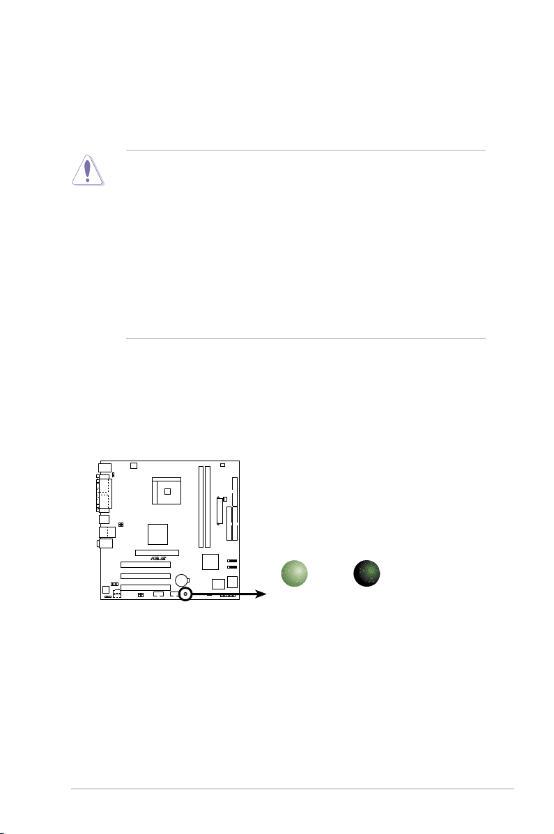
K8V-MX Onboard LED
SB_PWR
ON
Standby
Power
OFF
Powered
Off
Take note of the following precautions before you install motherboard components
or change any motherboard settings.
• Unplug the power cord from the wall socket before touching any component.
• Use a grounded wrist strap or touch a safely grounded object or to a metal
object, such as the power supply case, before handling components to
avoid damaging them due to static electricity.
• Hold components by the edges to avoid touching the ICs on them.
• Whenever you uninstall any component, place it on a grounded antistatic
pad or in the bag that came with the component.
• Before you install or remove any component, ensure that the ATX power
supply is switched off or the power cord is detac hed from the power
supply. Failure to do so may cause severe damage to the motherboard,
peripherals, and/or components.
Onboard LED
The motherboard comes with a standby power LED that lights up to indicate that
the system is ON, in sleep mode, or in soft-off mode. This is a reminder that you
should shut down the system and unplug the power cable before removing or
plugging in any motherboard component.
ASUS K8V-MX Motherboard 1-5
Page 16
PS/2
T: Mouse
B: Keyboar
d
Below:Mic In
Center:Line Out
Top:Line In
RJ-45
Top:
USB3
USB4
Bottom:
Socket 754
DDR DIMM1 (64 bit, 184-pin module)
DDR DIMM2 (64 bit, 184-pin module)
AD1888
CD
USBPW56
USBPW78
USB56
CLRTC
PCI1
PCI2
PCI3
VIA
K8M800
ATX12V
USBPW12
USBPW34
AGP
VIA
VT8237R
PRI_IDE
SEC_IDE
CR2032 3V
Lithium Cell
CMOS Power
SATA1
SATA2
CPU_FAN
Super
I/O
SB_PWR
CHA_FAN
4Mbit
BIOS
K8V-MX
AUX
KBPWR
FP_AUDIO
R
USB1
USB2
FLOPPY
COM1
PARALLEL PORT
VGA
ATXPWR
PANEL
USB78
SPDIF
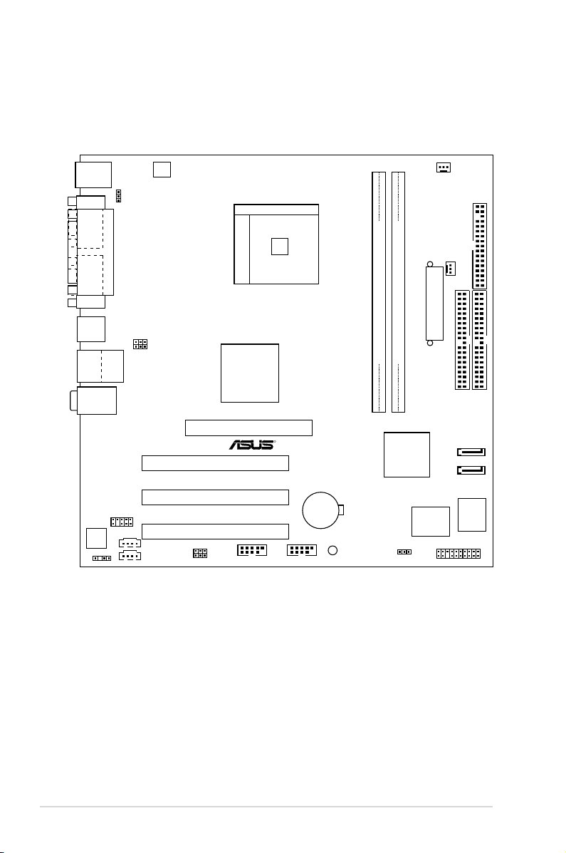
1.5 Motherboard Overview
1.5.1 Motherboard layout
1-6 Chapter 1: Product Introduction
Page 17
K8V-MX
R
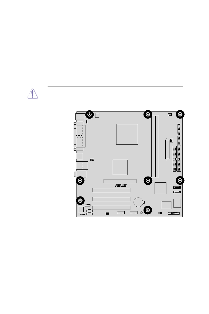
1.5.2 Placement direction
When installing the motherboard, make sure that you place it into the chassis in the
correct orientation. The edge with external ports goes to the rear part of the chassis
as indicated in the image below.
1.5.3 Screw holes
Place eight (8) screws into the holes indicated by circles to secure the motherboard
to the chassis.
Do not overtighten the screws! Doing so may damage the motherboard.
Place this side
towards
the rear of the
chassis
ASUS K8V-MX Motherboard 1-7
Page 18
K8V-MX
R
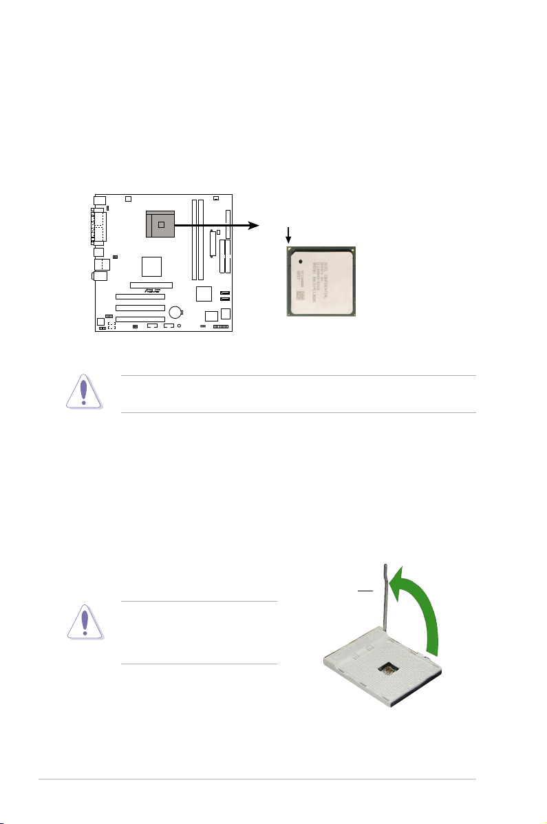
K8V-MX CPU Socket 754
Gold Arrow
1.6 Central Processing Unit (CPU)
1.6.1 Overview
The AMD Athlon™ 64 processor has a gold triangle in one corner. This mark indicates
the processor Pin A1 that should match a specific corner of the CPU socket.
Incorrect installation of the CPU into the socket may bend the pins and
severely damage the CPU!
1.6.2 Installing the CPU
Follow these steps to install a CPU.
1. Locate the 754-pin ZIF socket on the motherboard.
2. Unlock the s ock et by pre ssi ng the
lever sideways, then lift it up to a 90°
-100° angle.
1-8 Chapter 1: Product Introduction
Socket Lever
Make sure that the socket lever
is lif t ed up t o 9 0°- 1 00° an gle ,
otherwise the CPU does not fit in
completely.
Page 19
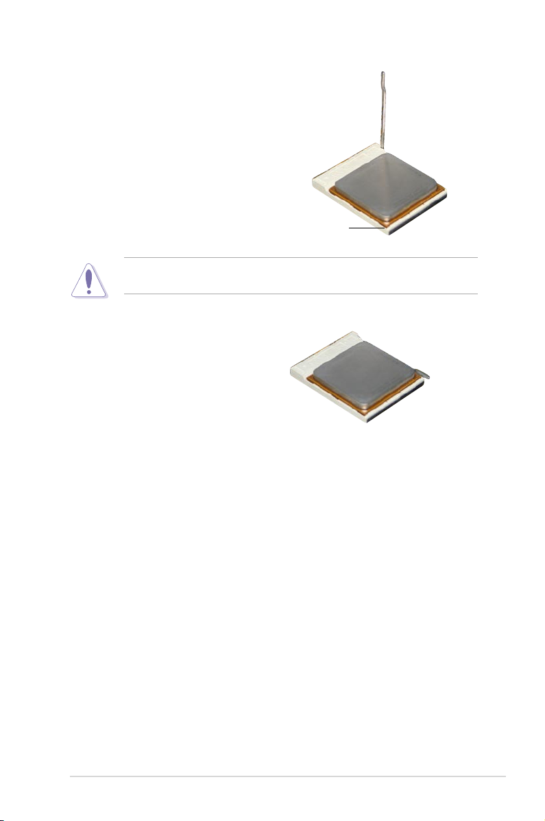
3. Position the CPU above the socket
such that the CPU corner with the gold
triangle matches the socket co rn er
with a small triangle.
4. Ca reful l y insert t he CPU i n to the
socket until it fits in place.
The CPU fits only in one correct orientation. DO NOT force the CPU into the
socket to prevent bending the pins and damaging the CPU!
5. When the CPU is in place, push down
the socket lever to secure the CPU.
Th e l eve r clicks on the side tab to
indicate that it is locked.
6. In s t a l l a CP U h e a t s i n k an d f a n
following the instructions that came
with the heatsink package.
7. Co n n ect t h e CP U fa n ca b l e to
th e CPU_ FAN co nn e c t o r o n t h e
motherboard.
Gold triangle
ASUS K8V-MX Motherboard 1-9
Page 20
1.7 System memory
K8V-MX
R
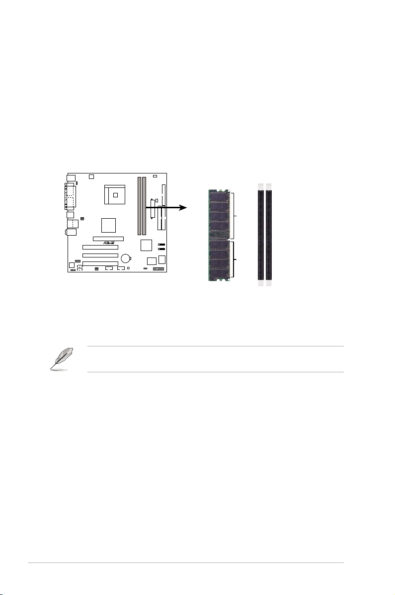
K8V-MX 184-Pin DDR DIMM sockets
80 Pins 104 Pins
DIMM1
DIMM2
1.7.1 Overview
The motherboard comes with two Double Data Rate (DDR) Dual Inline Memory
Module (DIMM) sockets. These sockets support up to 2GB system memory using
184-pin PC3200/PC2700/PC2100 unbuffered DDR DIMMs and allow up to 3.2 GB/s
data transfer rate.
The following figure illustrates the location of the DDR DIMM sockets.
1.7.2 Memory configurations
You may install 64 MB, 128 MB, 256 MB, 512 MB and 1 GB DDR DIMMs into the
DIMM sockets.
For optimum compatibility, it is recommended that you obtain memory modules
from qualified vendors. See the Qualified Vendors List (QVL) next page.
1-10 Chapter 1: Product Introduction
Page 21
Qualified DDR400 DIMMs
The following table lists the PC3200 (DDR400) memory modules that have been
tested and qualified for use with this motherboard.
Obtain DDR DIMMs only from qualified vendors for better system performance.
DDR400 Qualified Vendor List (QVL)
DIMM support
Size Vendor Model Brand Side(s) Component A* B*
256MB KINGSTON KVR400X64C3A/256 Hynix SS HY5DU56822BT-D43 •
512MB KINGSTON KVR400X64C3A/512 Hynix DS HY5DU56822BT-D43 • •
256MB KINGSTON KVR400X64C3A/256 PSC SS A2S56D30BTP • •
512MB KINGSTON KVR400X64C3A/512 Hynix SS HY5DU12822BT-D43 • •
256MB KINGSTON KVR400X64C3A/256 KINGSTON SS D3208DL3T-5A •
512MB KINGSTON KVR400X64C3A/512 KINGSTON DS D3208DH1T-5 • •
256MB KINGSTON KVR333X64C25/256 KINGSTON SS D3208DH1T-6 •
512MB KINGSTON KVR333X64C25/512 KINGSTON DS D3208DH1T-6 •
256MB KINGSTON KVR333X64C25/256 Hynix DS HY5DU56822BT-D43 • •
1GB KINGSTON KVR400X64C3A/1G Infineon DS HYB25D512800BE-5B • •
256MB Infineon HYS64D32300GU-5-C Infineon SS HYB25D256800CE-5C • •
512MB Infineon HYS64D64320GU-5-C Infineon DS HYB25D256800CE-5C • •
512MB Infineon HYS64D64300GU-5-B Infineon SS HYB25D512800CE-5B •
256MB Infineon HYS64D32300GU-5-C Infineon SS HYB25D256800CE-5C • •
512MB Infineon HYS64D64320GU-5-C Infineon DS HYB25D256800CE-6C • •
256MB HY HYMD232646D8J-D43 Hynix SS HY5DU56822DT-D43 • •
512MB HY HYMD264646D8J-D43 Hynix DS HY5DU56822DT-D43 • •
256MB HY HYMD232646D8J-J Hynix SS HY5DU56822BT-J • •
512MB HY HYMD264646D8J-J Hynix DS HY5DU56822BT-J • •
256MB CORSAIR VS256MB400 Value select SS VS32M8-5 2B0409 • •
256MB CORSAIR XMS3202v3.1 Infineon SS HYB25D256807BT-5B • •
512MB CORSAIR XMS3205v1.2 Winbond DS W942508CH-5 •
512MB CORSAIR VS512MB400 Value select DS VS32M8-5 2B0402 • •
256MB CORSAIR XMS2700v1.1 Winbond SS W942508BH-6 • •
256MB CORSAIR VS256MB333 SAMSUNG SS K4H5608380-TCB3 • •
512MB CORSAIR XMS2702v3.1 Mosel DS V58C2256804SAT6 • •
512MB CORSAIR XMS3205v1.2 Winbond DS W942508CH-6 • •
512MB MICRON MT16VDDT6464AG-335GB MICRON DS MT46V32M8TG-6TG • •
256MB MICRON MT8VDDT3264AG-335GB MICRON SS MT46V32M8TG-6TG • •
256MB MICRON MT8VDDT3264AG-40BGB MICRON SS MT46V32M8TG-5BG • •
512MB MICRON MT16VDDT6464AG-40BCB MICRON DS MT46V32M8TG-5BC • •
256MB SAMSUNG M368L3223FTN-CCC SAMSUNG SS K4H560838F-TCCC • •
512MB SAMSUNG M368L6423FTN-CCC SAMSUNG DS K4H560838F-TCCC • •
256MB SAMSUNG M368L3223FTN-CB3 SAMSUNG SS K4H560838F-TCB3 •
512MB SAMSUNG M368L6423FTN-CB3 SAMSUNG DS K4H560838F-TCB3 • •
256MB Winbond U24256ADWBG6H20 Winbond SS W942508CH-5 • •
256MB Winbond U24256AAWBG6H20 Winbond SS W942508CH-6 • •
512MB Winbond DDR333-512 Winbond DS W942508BH-6 • •
512MB Winbond U24512ADWBG6H20 Winbond DS W942508CH-5 • •
256MB Elpida U24256ADEPG6H20 Elpida SS DD2508AKTA-5C •
512MB Elpida U24512ADEPG6H20 Elpida DS DD2508AMTA • •
256MB Transcend DDR400-256 SAMSUNG SS K4H560838F-TCCC • •
256MB Transcend DDR400-256 Mosel SS V58C2256804SAT5B • •
256MB Transcend 103004-0720 PSC SS A2S56D3OBTP • •
512MB Transcend 102709-0001 PSC DS A2S56D3OATP • •
512MB Transcend DDR400-512 Mosel DS V58C2256804SAT5B •
512MB Transcend DDR400-512 SAMSUNG DS K4H560838F-TCCC • •
256MB Transcend 111448-0214 PSC SS A2S56D3OBTP • •
512MB Transcend DDR333-512 Hynix DS HY5DU56822CT-J •
256MB Pmi 3208GATA07-04A7 Pmi SS PM4D328D50406EU • •
512MB Pmi 3208GATA01-04A4 Pmi DS PM4D328S50403DU •
256MB KINGMAX MPMB62D-38LT3R Mosel SS V58C2256804SAT6 • •
512MB KINGMAX MPMC22D-38HT3R Hynix DS HY5DU56822BT-J • •
256MB KINGMAX MPXB62D-38KT3R KINGMAX SS KDL388P4LA-50 • •
(Continued on the next page)
ASUS K8V-MX Motherboard 1-11
Page 22

DDR400 Qualified Vendors List
DIMM support
Size Vendor Model Brand Side(s) Component A* B*
256MB Mosel V826632K24SATG-D3 Mosel SS V58C2256804SAT5 • •
512MB Mosel V826664K24SATG-D3 Mosel DS V58C2256804SAT5 •
256MB NANYA NT256D64S88B1G-5T NANYA SS NT5DS32M8BT-5T • •
512MB NANYA NT512D64S8HB1G-5T NANYA DS NT5DS32M8BT-5T • •
256MB Apacer 77.10636.46G SAMSUNG SS K4H560838E-TCCC • •
512MB Apacer 77.90728.U1G Apacer DS AM3A568AJT-6B • •
256MB Apacer 77.10636.56G Mosel SS V58C2256804Sat5B • •
512MB Apacer 77.10736.11G Infineon DS HYB25D256800BT-5B •
256MB Smart U24256ADSRG6H20 Smart SS D32M8XS50H3X4AMV •
256MB Smart U24256ADSRG6H20 Smart SS D32M8XS60HBX4AMV • •
512MB Smart U24512ADSRG6H20 Smart DS D32M8XS50H3X4AMV •
512MB Smart U24512ADSRG6H20 Smart DS D32M8XS60HBX4AMV • •
256MB TwinMOS DDR333-256 TwinMOS SS TMD7608F8E60B • •
256MB TwinMOS M2G9I08A-TT TwinMOS SS TMD7608F8E501 • •
512MB TwinMOS M2G9J16A-TT TwinMOS DS TMD7608F8E501 •
256MB Promos V826632K24SCTG-D0 Promos SS V58C2256804SCT5B • •
512MB Promos V826664K24SCTG-D0 Promos DS V58C2256804SCT5B • •
512MB BiaoXing BXXC22D-38KT3B BiaoXing DS VM256D328BT-5 • •
256MB Vdata MDYVD6F4G2880B1E0H Vdata SS VDD9616A8A-5C • •
Legend:
A - supp ort s one mod ule ins ert ed i nto eith er slo t , i n a Sing l e-c han nel mem ory
configuration.
B - supports on pair of modules inserted into either the blue slots or the black slots as one
pair of Dual-channel memory configuration.
SS - Single-sided
DS - Double-sided
1-12 Chapter 1: Product Introduction
Page 23

1.7.3 Installing a DIMM
Make sure to unplug the power supply before adding or removing DIMMs or
other system components. Failure to do so may cause severe damage to both
the motherboard and the components.
Follow these steps to install a DIMM.
1. Lo c a te the DIMM socke t s i n th e
motherboard.
2. Unlock a DIMM socket by pressing
the retaining clips outward.
3. Align a DIMM on the socket such that
the notch on the DIMM matches the
break on the socket.
A DDR DIMM is keyed with a notch so that it fits in only one direction. DO NOT
force a DIMM into a socket to avoid damaging the DIMM.
4. Fi r m l y i n s e r t t h e D I M M i nto th e
socket until the retaining clips snap
b a c k i n p l a c e a n d t h e D I M M i s
properly seated.
Unlocked Retaining Clip
1.7.4 Removing a DIMM
DDR DIMM notch
Locked Retaining Clip
Follow these steps to remove a DIMM.
1. Simultaneously press the retaining
clips outward to unlock the DIMM.
Support the DIMM lightly with your fingers when pressing the retaining clips.
The DIMM might get damaged when it flips out with extra force.
2. Remove the DIMM from the socket.
ASUS K8V-MX Motherboard 1-13
Page 24

1.8 Expansion slots
In the future, you may need to install expansion cards. The following sub-sections
describe the motherboard slots and the expansion cards that they support.
Make sure to unplug the power cord before adding or removing expansion
car d s . Fa ilur e to d o so ma y ca use y ou p h y sica l in j u ry a n d da mage
motherboard components.
1.8.1 Installing an expansion card
Follow these steps to install an expansion card.
1. Before installing the expansion card, read the documentation that came with it
and make the necessary hardware settings for the card.
2.
Remove the system unit cover (if your motherboard is already installed
in a chassis).
3. Remove the bracket opposite the slot that you intend to use. Keep the screw
for later use.
4. Align th e card connector with the slot and press firmly until the card is
completely seated on the slot.
5. Secure the card to the chassis with the screw you removed earlier.
6. Replace the system cover.
1.8.2 Configuring an expansion card
After installing the expansion card, configure the card by adjusting the software settings.
1. Turn on the system and change the necessary BIOS settings, if any. See
Chapter 2 for information on BIOS setup.
2. Assign an IRQ to the card. Refer to the tables on the next page.
3. Install the software drivers for the expansion card.
1-14 Chapter 1: Product Introduction
Page 25

Standard Interrupt Assignments
IRQ Priority Standard Function
0 1 System Timer
1 2 Keyboard Controller
2 N/A Programmable Interrupt
3 11 Communications Port (COM2)
4* 12 Communications Port (COM1)
5* 13 Sound Card (sometimes LPT2)
6 14 Floppy Disk Controller
7* 15 Printer Port (LPT1)
8 3 System CMOS/Real Time Clock
9* 4 ACPI Mode when used
10* 5 IRQ Holder for PCI Steering
11* 6 IRQ Holder for PCI Steering
12* 7 PS/2 Compatible Mouse Port
13 8 Numeric Data Processor
14* 9 Primary IDE Channel
15* 10 Secondary IDE Channel
These IRQs are usually available for ISA or PCI devices.
*
IRQ assignments for this motherboard
PCI slot 1 shared –– –– ––
PCI slot 2 –– shared –– ––
PCI slot 3 –– –– shared ––
AGP slot shared –– –– ––
When using PCI cards on shared slots, ensure that the drivers support “
Share IR Q” or that the cards do not need IRQ assi gnments; otherw ise,
conflicts will arise between the two PCI groups, making the system unstable
and the card inoperable.
INT A INT B INT C INT D
ASUS K8V-MX Motherboard 1-15
Page 26

1.8.3 PCI slots
K8V-MX
R
K8V-MX Accelerated Graphics Port (AGP)
Keyed for 1.5v
Th e P CI slots sup port LAN, S CSI , U SB,
and other PCI cards that comply with PCI
specifications. The figure below shows a LAN
card installed on a PCI slot.
1.8.4 AGP slot
The Ac c eler a t ed G r aphi c s Port ( AGP) s lot s uppor t s AGP 8 X (AGP 3.0)
specification. Note the notches on the card golden fingers to ensure that they fit the
AGP slot on your motherboard.
Install only 1.5V AGP cards on this motherboard! 3.3V AGP cards are not
supported in this motherboard.
1-16 Chapter 1: Product Introduction
Page 27

1.9 Jumpers
K8V-MX
R
K8V-MX Clear RTC RAM
CLRTC
Normal Clear CMOS
(Default)
3
2
21
1. Clear RTC RAM (CLRTC)
This jumper allows you to clear the Real Time Clock (RTC) RAM in CMOS.
You can clear the CMOS memory of date, time, and system setup parameters
by erasing the CMOS RTC RAM data. The RAM data in CMOS, that include
system setup information such as system passwords, is powered by the
onboard button cell battery.
To erase the RTC RAM:
1. Turn OFF the computer and unplug the power cord.
2. Remove the onboard battery.
3. Move the jumper cap from pins 1-2 (default) to pins 2-3. Keep the cap on
pins 2-3 for about 5~10 seconds, then move the cap back to pins 1-2.
4. Replace the battery.
5. Plug the power cord and turn ON the computer.
6. Hold down the <Del> key during the boot process and enter BIOS setup
to re-enter data.
Except when clearing the RTC RAM, never remove the cap on the CLRTC
jumper default position. Removing the cap will cause system boot failure!
ASUS K8V-MX Motherboard 1-17
Page 28

3
2
21
K8V-MX
R
K8V-MX USB device wake-up
+5V
(Default)
+5VSB
USBPW12
USBPW34
3
2
21
+5V
(Default)
+5VSB
USBPW78
USBPW56
2. Keyboard power (3-pin KBPWR)
K8V-MX
R
K8V-MX Keyboard power setting
(Default)
+5V +5VSB
KBPWR
1
2
3
2
This jumper allows you to enable or disable the keyboard wake-up feature.
Set this jumper to pins 2-3 (+5VSB) if you wish to wake up the computer when
you press a key on the keyboard (the default value is [Disabled]). This feature
requires an ATX power supply that can supply at least 1A on the +5VSB lead,
and a corresponding setting in the BIOS (see section 2.5.5 APM Configuration).
3. USB device wake-up (3-pin USBPWR12, USBPWR34, USBPWR56, USBPWR78)
Set these jumpers to +5V to wake up the computer from S1 sleep mode (CPU
stopped, DRAM refreshed, system running in low power mode) using the
connected USB devices. Set to +5VSB to wake up from S3 sleep mode (no
power to CPU, DRAM in slow refresh, power supply in reduced power mode).
The USBPWR12 and USBPWR34 jumpers are for the rear USB ports. The
USBPWR56 and USBPWR78 jumpers are for the internal USB connectors that
you can connect to additional USB ports.
• The USB device wake-up feature requires a power supply that can provide
500mA on the +5VSB lead for each USB port; otherwise, the system would
not power up.
• The total current consumed must NOT exceed the power supply capability
(+5VSB) whether under normal condition or in sleep mode.
1-18 Chapter 1: Product Introduction
Page 29

1.10 Connectors
1
2
11
10 7
4
5
6
3
9
8
Th is s ect ion des cri bes and ill ustrate s t he r ear panel a nd inte rna l
connectors on the motherboard.
1.10.1 Rear panel connectors
1. PS/2 mouse port (green).
2. Parallel port.
3. LAN (RJ-45) port.
through a network hub.
4. Line In port.
audio sources. In 4- or 6-channel mode, the function of this port becomes Rear
Speaker Out.
5. Line Out port.
In 4- or 6-channel mode, the function of this port becomes Front Speaker Out.
6. Microphone port.
mode, the function of this port becomes Bass/Center Speaker.
Audio ports function variation
Audio ports Headphone /2-Channel 4-Channel 6-Channel
Light Blue Line In Rear Speaker Out Rear Speaker Out
Lime Line Out Front Speaker Out Front Speaker Out
Pink Mic In Mic In Bass/Center
This 25-pin port connects a parallel printer, a scanner, or other devices.
This Line In (light blue) port connects a tape player or other
This Line Out (lime) port connects a headphone or a speaker.
The functions of the Line Out, Line In, and Microphone ports change when you
select the 4- or 6-channel audio configuration as shown in the following table.
This 6-pin port is for a PS/2 mouse.
This port allows connection to a Local Area Network (LAN)
This Mic (pink) port connects a microphone. In 6-channel
ASUS K8V-MX Motherboard 1-19
Page 30

7. USB 2.0 ports 3 and 4.
available for connecting USB 2.0 devices.
8. USB 2.0 ports 1 and 2.
available for connecting USB 2.0 devices
9. Video Graphics Adapter port.
VGA-compatible devices.
10. Serial port.
11. PS/2 keyboard port (purple).
This 9-pin COM1 port is for pointing devices or other serial devices.
These two 4-pin Universal Serial Bus (USB) ports are
These two 4-pin Universal Serial Bus (USB) ports are
This 15-pin port is for a VGA monitor or other
This port is for a PS/2 keyboard.
1-20 Chapter 1: Product Introduction
Page 31

1.10.2 Internal connectors
K8V-MX
R
K8V-MX Floppy disk drive connector
FLOPPY
NOTE: Orient the red markings on
the floppy ribbon cable to PIN 1.
PIN 1
K8V-MX
R
K8V-MX Internal audio connectors
CD (Black)
Right Audio Channel
Left Audio Channel
Ground
AUX (White)
1. Floppy disk drive connector (34-1 pin FLOPPY)
This connector is for the provided floppy drive (FDD) signal cable. Insert one
end of the cable to this connector, then connect the other end to the signal
connector at the back of the floppy disk drive.
Pin 5 on the connector is removed to prevent incorrect cable connection when
using an FDD cable with a covered Pin 5.
2. Internal audio connector (4-pin CD, AUX)
These connectors allow you to receive stereo audio input from sound sources
such as a CD-ROM, TV tuner, or MPEG card.
ASUS K8V-MX Motherboard 1-21
Page 32

K8V-MX
R
K8V-MX Digital audio connector
+5V
SPDIFOUT
GND
SPDIF_OUT
3. IDE connectors (40-1 pin PRI_IDE, SEC_IDE)
K8V-MX
R
K8V-MX IDE connectors
NOTE: Orient the red markings
(usually zigzag) on the IDE
ribbon cable to PIN 1.
SEC_IDE
PIN 1
PRI_IDE
PIN 1
These connectors support the provided Ultra ATA/133 IDE hard disk ribbon
cable. Connect the cableʼs blue connector to the primary (recommended) or
secondary IDE connector, then connect the gray connector to the Ultra ATA/133
slave device (hard disk drive) and the black connector to the Ultra ATA/133
master device. Connecting non-Ultra ATA/133 devices to the secondary IDE
connector is recommended.
• Pin 20 on each IDE connector is removed to match the covered hole on
the Ultra ATA cable connector. This prevents incorrect orientation when you
connect the cables.
• For Ultra ATA/133 IDE devices, use an 80-conductor IDE cable.
• The hole near the blue connector on the Ultra ATA/133 cable is intentional.
4. Digital audio connector (3- pin SPDIF)
This connector is for the S/PDIF audio module that allows digital sound input.
• Use 75 ohm impedance matched coaxial cables for your S/PDIF connection.
• The S/PDIF module is purchased separately.
1-22 Chapter 1: Product Introduction
Page 33

5. CPU and chassis fan connectors (3-pin CPU_FAN, CHA_FAN)
K8V-MX
R
K8V-MX Fan connectors
CPU_FAN
CHA_FAN
GND
Rotation
+12V
GND
Rotation
+12V
K8V-MX
R
K8V-MX ATX power connectors
ATXPWRATX12V
+12V DC
GND
+12V DC
GND
+3.3VDC
-12.0VDC
GND
PS_ON#
GND
GND
GND
-5.0VDC
+5.0VDC
+5.0VDC
PWR_OK
+12.0VDC
+3.3VDC
+3.3VDC
GND
+5.0VDC
GND
+5.0VDC
GND
+5VSB
The fan connectors support cooling fans of 350mA~740mA (8.88W max.) or
a total of 1A~2.22A (26.64W max.) at +12V. Connect the fan cables to the fan
connectors on the motherboard, making sure that the black wire of each cable
matches the ground pin of the connector.
Do not forget to connect the fan cables to the fan connectors. Insufficient air
flow within the system can damage the motherboard components. These are
not jumpers! DO NOT place jumper caps on the fan connectors!
6. ATX power connectors (20-pin ATXPWR, 4-pin ATX12V)
These connectors are for an ATX 12V power supply. The plugs from the power
supply are designed to fit these connectors in only one orientation. Find the
proper orientation and push down firmly until the connectors fit completely.
• Do not forget to connect the 4-pin ATX +12V power plug; otherwise, the
system does not boot up.
• Make sure that your ATX 12V power supply can provide 12A on the +12V
lead and at least 1A on the +5-volt standby lead (+5VSB). The minimum
recommended wattage is 300 W, or 350 W for a fully configured system.
The sy stem c an become unstable or w ill no t boot up if the p ower i s
inadequate.
ASUS K8V-MX Motherboard 1-23
Page 34

K8V-MX
R
BLINE_OUT_L
MIC2
Line out_R
Line out_L
BLINE_OUT_R
NC
MICPWR
+5VA
AGND
K8V-MX Front panel audio connector
FP_AUDIO
7. Serial ATA connectors (7-pin SATA1, SATA2)
K8V-MX
R
K8V-MX SATA connectors
SATA2
GND
RSATA_TXP2
RSATA_TXN2
GND
RSATA
_RXP2
RSATA
_RXN2
GND
SATA1
GND
RSATA_TXP1
RSATA_TXN1
GND
RSATA
_RXP1
RSATA
_RXN1
GND
These connectors support the thin Serial ATA cables for Serial ATA hard
disks. If you installed Serial ATA hard disks, you may create a RAID 0 or
RAID 1 configuration.
8. Front panel audio connector (10-1 pin FP_AUDIO)
T his interfac e f or the In tel® fro nt panel au dio cab le allows c onv eni ent
connection and control of audio devices.
1-24 Chapter 1: Product Introduction
Page 35

9. USB connectors (10-1 pin USB56, USB78)
K8V-MX
R
USB56
USB+5V
USB_P6-
USB_P6+
GND
NC
USB+5V
USB_P5-
USB_P5+
GND
1
USB78
USB+5V
USB_P8-
USB_P8+
GND
NC
USB+5V
USB_P7-
USB_P7+
GND
1
K8V-MX USB 2.0 connectors
These connectors are for USB 2.0 ports. Connect the USB module cable to
any of these connectors, then install the module to a slot opening at the back of
the system chassis. These USB connectors comply with USB 2.0 specification
that supports up to 480 Mbps connection speed.
NEVER connect a
1394 cable
to the USB connectors. Doing so will damage
the motherboard!
The USB module is purchased separately.
ASUS K8V-MX Motherboard 1-25
Page 36

* Requires an ATX power supply.
PLED-
PWR
+5V
Speaker
PLED
Ground
RESET
Ground
Reset
Ground
Ground
PLED+
IDELED
IDELED+
IDE_LED
PWRSW
SPEAKER
PANEL
K8V-MX
R
K8V-MX System panel connector
10. System panel connector (20-1 pin PANEL)
This connector supports several system chassis-mounted functions.
System power LED
•
This connector is for the system power LED. Connect the chassis power LED
cable to this connector. The system power LED lights up when you turn on
the system power, and blinks when the system is in sleep mode.
System warning speaker
•
This connector is for the chassis-mounted system warning speaker.
The speaker allows you to hear system beeps and warnings.
Reset button (2-pin RESET)
•
This connector is for the chassis-mounted reset button for system
reboot without turning off the system power.
ATX power button/soft-off button (2-pin PWRBTN)
•
This connector is for the system power button. Pressing the power
button turns the system on or puts the system in sleep or soft-off
mode depending on the BIOS settings. Pressing the power switch for
more than four seconds while the system is ON turns the system OFF.
System Management Interrupt (2-pin SMI)
•
This connector is for the chassis-mounted suspend switch that allows
you to manually place the system into a suspend mode, or “green”
mo de. When in suspen d mode, the system act ivity is i nstantly
decreased to save power and to expand the life of certain system
components.
Hard disk drive activity LED (2-pin HDLED)
•
This connector is for the HDD Activity LED. Connect the HDD Activity
LED cable to this connector. The IDE LED lights up or flashes when
data is read from or written to the HDD.
1-26 Chapter 1: Product Introduction
Page 37

Chapter 2
This chapter tells how to change system settings
through the BIOS Setup menus, and provides
detailed descriptions of the BIOS parameters.
BIOS Information
Page 38

2.1 Managing and Updating Your BIOS
The following utilities allow you to manage and update the motherboard Basic
Input/Output System (BIOS) setup.
1.
AFUDOS
2.
ASUS EZ Flash
3.
ASUS CrashFree BIOS 2
mother board support CD.
Refer to the corresponding section for each utility.
2.1.1 Creating a bootable floppy disk
1. Do either one of the following to create a bootable floppy disk.
DOS environment
Insert a 1.44MB floppy disk into the drive. At the DOS prompt, type:
Windows® XP environment
a. Insert a 1.44MB floppy disk into the floppy disk drive.
b. From your Windows® desktop, click on
c. Select the
d. Click
e. Select
2. Copy the original (or the latest) motherboard BIOS to the bootable floppy disk.
(Updates the BIOS in DOS mode using a bootable floppy disk.)
(Updates the BIOS using a floppy disk during POST.)
- Updates the BIOS using a bootable floppy disk or the
• Save a copy of the original motherboard BIOS file to a bootable floppy disk
in case you need to restore the BIOS in the future. Copy the original
motherboard BIOS using the AFUDOS utility.
• Refer to the system builderʼs website for details about updating the BIOS.
format A:/S
File
window appears.
click
Start
then press <Enter>.
Start
3 1/2 Floppy Drive
from the menu, then select
Create an MS-DOS startup disk
.
icon.
Format
, then select
. A
Format 3 1/2 Floppy Disk
from the format options field, then
My Computer
.
2.1.2 Using AFUDOS to copy the current BIOS
The AFUDOS.EXE utility can also be used to copy the current system BIOS
settings to a floppy or hard disk. The copy can be used as a backup in case the
system BIOS fails or gets corrupted.
1. At the DOS prompt, type the command line:
afudos /o[filename]
where “filename” can be any user-provided filename of not more than eight
alphanumeric characters for the main filename and thre e alphanumeric
characters for the extension name.
Press <Enter>.
2-2 Chapter 2: BIOS Information
Page 39

The BIOS information on the screen is for reference only. What you see on your
screen may not be exactly the same as shown.
Main filename Extension name
A:\>afudos /oMYBIOS03.rom
AMI Firmware Update Utility - Version 1.10
Copyright (C) 2002 American Megatrends, Inc. All rights reserved.
Reading flash ..... 0x0008CC00 (9%)
2. The utility will copy the current system BIOS by default to the floppy disk. Make
sure that the floppy disk is not write-protected and has enough space (at least
600KB) to store the file.
A:\>afudos /oMYBIOS03.rom
AMI Firmware Update Utility - Version 1.10
Copyright (C) 2002 American Megatrends, Inc. All rights reserved.
Reading flash ..... done
A:\>
When the BIOS copy process is complete, the utility returns to the DOS prompt.
2.1.3 Using AFUDOS to update the BIOS
The AFUDOS is a DOS-based application that lets you update the BIOS file using
a bootable floppy diskette. AFUDOS also allows you to copy the original BIOS file
to a floppy diskette.
To update the BIOS using the AFUDOS.EXE:
1. Download the latest BIOS file from the website provided by the system builder.
Write the BIOS filename on a piece of paper. You need to type the exact BIOS
file name at the prompt.
2. Copy the AFUDOS.EXE utility from the support CD to the bootable floppy disk
that contains the BIOS file.
3. Boot the system from the floppy disk.
ASUS K8V-MX Motherboard 2-3
Page 40

4. At the DOS prompt, type the command line:
afudos /i[filename.rom]
where [filename.rom] means the latest (or original) BIOS file that you copied to
the bootable floppy disk.
5. Press <Enter>. The screen displays the status of the update process.
The BIOS information on the screen is for reference only. What you see on your
screen may not be exactly the same as shown.
A:\>afudos /iK8V-MX.rom
AMI Firmware Update Utility - Version 1.10
Copyright (C) 2002 American Megatrends, Inc. All rights reserved.
Reading file ..... done
Erasing flash .... done
Writing flash .... 0x0008CC00 (9%)
DO NOT shut down or reset the system while updating the BIOS! Doing so can
cause system boot failure!
When the BIOS update process is complete, the utility returns to the DOS prompt.
A:\>afudos /iK8V-MX.rom
AMI Firmware Update Utility - Version 1.10
Copyright (C) 2002 American Megatrends, Inc. All rights reserved.
Reading file ..... done
Erasing flash .... done
Writing flash .... 0x0008CC00 (9%)
Verifying flash .. done
A:\>
6. Reboot the system from the hard disk.
2-4 Chapter 2: BIOS Information
Page 41

2.1.4 Using ASUS EZ Flash to update the BIOS
The ASUS EZ Flash feature allows you to easily update the BIOS without
having to go through the long process of booting from a floppy disk and
using a DOS-based utility. The EZ Flash is built-in the BIOS LPC chip so
it is accessible by simply pressing <Alt> + <F2> during the Power-On Self
Tests (POST).
To update the BIOS using ASUS EZ Flash:
1. Visit the system builder website to download the latest BIOS file for your
motherboard and rename it to
2. Reboot the system.
3. To launch EZ Flash, press <Alt> + <F2> during POST to display the following.
User recovery requested. Starting BIOS recovery...
Checking for floppy...
• If there is no floppy disk in the drive, the error message “Floppy not found!” appears.
• If the correct BIOS file is not found in the floppy disk, the error message
“K8V-MX.ROM not found!” is displayed.
K8V-MX.ROM
. Save the BIOS file to a floppy disk.
4. Insert the floppy disk that contains the BIOS file. If the
found in the floppy disk, EZ Flash performs the BIOS update process and
automatically reboots the system when done.
DO NOT shut down or reset the system while updating the BIOS! Doing so can
cause system boot failure!
User recovery requested. Starting BIOS recovery...
Checking for floppy...
Floppy found!
Reading file “k8v-mx.rom”. Completed.
Start flashing...
Flashed successfully. Rebooting.
ASUS K8V-MX Motherboard 2-5
K8V-MX.ROM
file is
Page 42

2.2 BIOS Setup Program
The BIOS software is constantly being updated so the BIOS setup screens and
descriptions in this section are for reference purposes only, and may not exactly
match what you see on your screen.
This motherboard supports a programmable Low Pin Count (LPC) chip that you
can update using the provided utility described in section “2.1 Managing and
updating your BIOS.”
Use the BIOS Setup program when you are installing a motherboard, reconfiguring
your system, or prompted to “Run Setup”. This section explains how to configure
your system using this utility.
Even if you are not prompted to use the Setup program, you can change the
configuration of your computer in the future. For example, you can enable the
security password feature or make changes to the power management settings.
This requires you to reconfigure your system using the BIOS Setup program so
that the computer can recognize these changes and record them in the CMOS
RAM of the LPC chip.
The LPC chip on the motherboard stores the Setup utility. When you start up
the computer, the system provides you with the opportunity to run this program.
Press <Delete> during the Power-On Self Test (POST) to enter the Setup utility;
otherwise, POST continues with its test routines.
To enter Setup after POST, restart the system by pressing <Ctrl+Alt+Delete>, or by
pressing the reset button on the system chassis. You can also restart by turning the
system off and then back on. Do this last option only if the first two fail.
The Setup program is designed to make it as easy to use as possible. Being a
menu-driven program, it lets you scroll through the various sub-menus and make
your selections among the predetermined choices.
2-6 Chapter 2: BIOS Information
Page 43

2.2.1 BIOS menu screen
Configuration fieldsMenu items
General helpMenu bar
System Time [17:08:35]
System Date [Mon 04/19/2004]
Legacy Diskette A [1.44M, 3.5 in.]
Diskette Write Protect [Disabled]
Primary IDE Master [ST340014A]
Primary IDE Slave [Not Detected]
Seconday IDE Master [ASUS DVD-E616P2]
Secondary IDE Slave [Not Detected]
System Information
v02.54 (C)Copyright 1985-2003, American Megatrends, Inc.
Sub-menu items
Use [ENTER], [TAB]
or [SHIFT-TAB] to
select a field.
Use [+] or [-] to
configure System Time.
Select Screen
←→
Select Item
↑↓
+- Change Field
Enter Go to Sub Screen
F1 General Help
F10 Save and Exit
ESC Exit
Navigation keys
2.2.2 Menu bar
The menu bar on top of the screen has the following main items:
Main
Advanced
Power
For changing the system boot configuration
Boot
Exit
To select an item on the menu bar, press the right or left arrow key on the keyboard
until the desired item is highlighted.
For changing the basic system configuration
For changing the advanced system settings
For changing the advanced power management (APM)
configuration
For selecting the exit options and loading default settings
2.2.3 Navigation keys
At the bottom right corner of a menu screen are the navigation keys for that
particular menu. Use the navigation keys to select items in the menu and change
the settings.
Some of the navigation keys differ from one screen to another.
ASUS K8V-MX Motherboard 2-7
Page 44

2.2.4 Menu items
The highlighted item on the menu bar displays the specific items for that menu.
For example, selecting
The other items (Advanced, Power, Boot, and Exit) on the menu bar have their
respective menu items.
shows the Main menu items.
Main
2.2.5 Sub-menu items
A solid triangle before each item on any menu screen means that the item has a
sub-menu. To display the sub-menu, select the item, then press <Enter>.
2.2.6 Configuration fields
These fields show the values for the menu items. If an item is user-configurable,
you can change the value of the field opposite the item. You cannot select an item
that is not user-configurable.
A configurable field is enclosed in brackets, and is highlighted when selected. To
change the value of a field, select it then press <Enter> to display a list of options.
Refer to “2.2.7 Pop-up window”.
2.2.7 Pop-up window
Select a menu item then press <Enter> to display a pop-up window with the
configuration options for that item.
2.2.8 Scroll bar
A scroll bar appears on the right side of a menu screen when there are items
that do not fit on the screen. Press the Up/Down arrow keys or <PageUp> /
<PageDown> keys to display the other items on the screen.
2.2.9 General help
At the top right corner of the menu screen is a brief description of the selected item.
2-8 Chapter 2: BIOS Information
Page 45

2.3 Main Menu
When you enter the BIOS Setup program, the Main menu screen appears, giving
you an overview of the basic system information.
Refer to section “2.2.1 BIOS menu screen” for information on the menu screen
items and how to navigate through them.
System Time [17:08:35]
System Date [Mon 04/19/2005]
Legacy Diskette A [1.44M, 3.5 in.]
Diskette Write [Disabled]
Primary IDE Master [ST340014A]
Primary IDE Slave [Not Detected]
Seconday IDE Master [ASUS DVD-E616P2]
Secondary IDE Slave [Not Detected]
System Information
v02.54 (C)Copyright 1985-2003, American Megatrends, Inc.
Use [ENTER], [TAB]
or [SHIFT-TAB] to
select a field.
Use [+] or [-] to
configure System Time.
Select Screen
←→
Select Item
↑↓
+- Change Field
Tab Select Field
F1 General Help
F10 Save and Exit
ESC Exit
2.3.1 System Time [xx:xx:xxxx]
Allows you to set the system time.
2.3.2 System Date [Day xx/xx/xxxx]
Allows you to set the system date.
2.3.3 Legacy Diskette A [1.44M, 3.5 in.]
Sets the type of floppy drive installed. Configuration options: [Disabled]
[360K, 5.25 in.] [1.2M , 5.25 in.] [720K , 3.5 in.] [1.44M, 3.5 in.] [2.88M, 3.5 in.]
2.3.4 Diskette Write [Disabled]
Enabling this item allows you to write to a floppy disk. If set to [Disabled], the floppy
disk is write-protected.Configuration options: [Disabled] [Enabled]
ASUS K8V-MX Motherboard 2-9
Page 46

2.3.5 Primary/Secondary IDE Master/Slave
While entering Setup, BIOS automatically detects the presence of IDE devices.
There is a separate sub-menu for each IDE device. Select a device item then press
<Enter> to display the IDE device information.
Primary IDE Master
Device : Hard Disk
Vendor : ST340014A
Size : 40.0GB
LBA Mode : Supported
Block Mode : 16 Sectors
PIO Mode : 4
Async DMA : MultiWord DMA-2
Ultra DMA : Ultra DMA-5
SMART Monitoring: Supported
Type [Auto]
LBA/Large Mode [Auto]
Block (Multi-Sector Transfer) M [Auto]
PIO Mode [Auto]
DMA Mode [Auto]
SMART Monitoring [Auto]
32Bit Data Transfer [Disabled]
v02.54 (C)Copyright 1985-2003, American Megatrends, Inc.
Select the type
of device connected
to the system.
Select Screen
←→
Select Item
↑↓
+- Change Option
F1 General Help
F10 Save and Exit
ESC Exit
The BIOS automatically detects the values opposite the dimmed items (Device,
Vendor, Size, LBA Mode, Block Mode, PIO Mode, Async DMA, Ultra DMA, and
SMART monitoring). These values are not user-configurable. These items show
N/A if no IDE device is installed in the system.
Type [Auto]
Selects the type of IDE drive.
Configuration options: [Auto] [Not Installed] [CDROM] [ARMD]
LBA/Large Mode [Auto]
Enables or disables the LBA/Large mode. Setting to Auto enables the LBA/Large
mode if the device supports this mode, and if the device was not previously
formatted with LBA mode disabled. Configuration options: [Auto] [Disabled]
Block (Multi-Sector Transfer) [Auto]
Enables or disables data multi-sectors transfers. When set to Auto, the data
transfer from and to the device occurs multiple sectors at a time if the device
supports multi-sector transfer feature. When set to Disabled, the data transfer from
and to the device occurs one sector at a time.
Configuration options: [Auto] [Disabled]
PIO Mode [Auto]
Selects the PIO mode. Configuration options: [Auto] [0] [1] [2] [3] [4]
2-10 Chapter 2: BIOS Information
Page 47

DMA Mode [Auto]
Selects the DMA mode. Configuration options: [Auto] [SWDMA0] [SWDMA1]
[SWDMA2] [MWDMA0] [MWDMA1] [MWDMA2] [UDMA0] [UDMA1] [UDMA2]
[UDMA3] [UDMA4] [UDMA5]
SMART Monitoring [Auto]
Sets the Smart Monitoring, Analysis, and Reporting Technology.
Configuration options: [Auto] [Disabled] [Enabled]
32Bit Data Transfer [Disabled]
Enables or disables 32-bit data transfer.
Configuration options: [Disabled] [Enabled]
2.3.6 System Information
This menu gives you an overview of the general system specifications. The items
in this menu are auto-detected by the BIOS.
AMI BIOS
Version : 08.00.09
Revision : 01.07.1711
Build Date : 06/14/05
ID : A0310001
System Memory
Size : 256MB
AMI BIOS
Displays the auto-detected BIOS information.
System Memory
Displays the auto-detected system memory.
ASUS K8V-MX Motherboard 2-11
Page 48

2.4 Advanced menu
The Advanced menu items allow you to change the settings for the CPU and other
system devices.
Take caution when changing the settings of the Advanced menu items.
Incorrect field values can cause the system to malfunction.
Configure CPU.
CPU Configuration
Chipset
Onboard Devices Configuration
PCIPnP
System Frequency/Voltage Configuration
Select Screen
←→
Select Item
↑↓
Enter Go to Sub Screen
F1 General Help
F10 Save and Exit
ESC Exit
v02.54 (C)Copyright 1985-2003, American Megatrends, Inc.
2.4.1 CPU Configuration
The ite ms i n t his men u sho w t he C PU- rela ted info rmat ion that the BIO S
automatically detects.
HyperTransport(HT) Configuration
Memory Configuration
Processor
Type : AMD Athlon(tm)64 Processor 3000+
Speed : 2000MHz
L1DC Size : 64KB
L1IC Size : 64KB
L2 Size : 512KB
CPUID : F48
Patch ID : 39
HyperTransport
Configuration
Options
Configure CPU.
2-12 Chapter 2: BIOS Information
Page 49

HyperTransport (HT) Configuration
HT Frequency [800 MHz]
HT DATA Width(Upstream) [16BIT]
HT DATA Width(Downstream) [16BIT]
K8CPU to AGP
HyperTransport
Frequency Selection
HT Frequency [800MHz]
Allows frequency selection of Hyper Transport transfer from K8 CPU to AGP.
Configuration options: [200MHz] [400MHz] [600MHz] [800MHz]
HT DATA Width (Upstream) [16BIT]
Allows selection of Hyper Transport upstream data width. Configuration options:
[16BIT] [8BIT]
HT DATA Width (Downstream) [16BIT]
Allows selection of Hyper Transport downstream data width. Configuration options:
[16BIT] [8BIT]
ASUS K8V-MX Motherboard 2-13
Page 50

Memory Configuration
Memory Configuration
Memory Configuration
Memory Configuration
Memory Configuration
Memclock Mode [Auto]
MCT Timing Mode [Auto]
User Config Mode [Auto]
Burst Length [4 Beats]
Enable Clock to All DIMMs [Disabled]
SoftWare Memory Hole [Enabled]
HardWare Memory Hole [Disabled]
MEMCLK can be set
by the code using
AUTO, or if you use
LIMIT, you can set
one of the standard
values.
Memclock Mode [Auto]
Allows you to set the memory clock mode. Set by the code using [Auto] or
select [Manual] to set using one of the standard values. Configuration options:
[Auto] [Limit]
MCT Timing Mode [Auto]
Allows you to set the MCT Timing Mode manually or auto. Configuration
options: [Auto] [Manual]
User Config Mode [Auto]
Sets the User Config Mode. Configuration options: [Auto] [Manual]
Burst Length [4 Beats]
Sets the Burst Length. Configuration options: [8 Beats] [4 Beats] [2 Beats]
Enable Clock to All DIMMs [Disabled]
Allows you to enable or disable the Clock to All DIMM. Configuration options:
[Disabled] [Enabled]
SoftWare Memory Hole [Enabled]
Allowsyou to enable or disable the SoftWare memory Hole. Configuration
options: [Disabled] [Enabled]
HardWare Memory Hole [Enabled]
Allowsyou to enable or disable the HardWare memory Hole. Configuration
options: [Disabled] [Enabled]
2-14 Chapter 2: BIOS Information
Page 51

2.4.2 Chipset
The Chipset menu allows you to change the advanced chipset settings. Select an
item then press <Enter> to display the sub-menu.
Options for VIA AGP
AGP Bridge Configuration
Southbridge Configuration
USB Configuration
AGP Bridge Configuration
Chipset
CPU Direct Access OnChip VGA [Disabled]
OnChip VGA Frame Buffer Size [64MB]
Dithering [Disabled]
Primary Graphics Adapter [AGP]
Search for MDA Resources [No]
VLink 8X Supported [Enabled]
AGP Mode [AGP 8X]
AGP Fast Write [Eabled]
Graphics Aperture Size [64MB]
AGP 3.0 Calibration cycle [Disabled]
DBI Output for AGP Trans [Disabled]
v02.54 (C)Copyright 1985-2003, American Megatrends, Inc.
Enable/Disable
CPU direct frame
bufferr to increase
performance after
PCI enumerate.
Select Screen
←→
Select Item
↑↓
+- Change Option
F1 General Help
F10 Save and Exit
ESC Exit
CPU Direct Access OnChip VGA [Disabled]
En abl es or d isa ble s the C PU d ire ct frame b uffer. C onf igu rat ion o pti ons :
[Disabled] [Enabled]
OnChip VGA Frame Buffer Size [64MB]
Sets the size of the main memory shared as video RAM. Configuration options:
[None] [8MB] [16MB] [32MB] [64MB]
Dithering [Disabled]
Enables or disables support for 18-bit LCD panel to 24-bit color depth under
different resolutions. Configuration options: [Disabled] [Enabled]
Primary Graphics Adapter [AGP]
Allows you to select the mode of Primary Graphics Adapter. Configuration options:
[AGP] [PCI]
ASUS K8V-MX Motherboard 2-15
Page 52

Search for MDA Resources [No]
Sets whether to allow search for MDA resources. Configuration options: [No] [Yes]
VLink 8X supported [Enabled]
Enables or disables support for VLink 8X. Configuration options: [Disabled] [Enabled]
AGP Mode [AGP 8X]
This motherboard supports the AGP 8X interface that transfers video data at
2.12GB/s. AGP 8X is backward-compatible, so you can keep the default [AGP 4X]
mode even if you are using an AGP 8X video card. When set to [AGP 4X] mode,
the AGP interface only provides a peak data throughput of 1.06GB/s even if you
are using an AGP 8X video card. Configuration options: [AGP 8X] [AGP 4X]
The [AGP 8X] option appears only when you install an AGP 8X graphics card.
AGP Fast Write [Enabled]
Ena ble s or disa ble s the AGP Fast Writ e feat ure . Conf igur ati on opt ions :
[Enabled] [Disabled]
Graphics Aperture Size [64MB]
All o ws y ou t o selec t the size of m a pped memor y for AGP grap hic d ata.
Configuration options: [256MB] [128MB] [64MB] [32MB]
AGP 3.0 Calibration cycle [Disabled]
Enables or disables the AGP Calibration mechanism. Configuration options:
[Disabled] [Enabled]
DBI Output for AGP Trans [Disabled]
Enab les or disables the DBI ou tp ut for AGP Trans. Con figuratio n o ptions:
[Disabled] [Enabled]
2-16 Chapter 2: BIOS Information
Page 53

Southbridge Configuration
MPS Revision [1.4]
PCI Delay Transaction [Enabled]
Sets to MPS revision
value
MPS Revision [1.4]
Sets the MPS revision value. Configuration options: [1.1] [1.4]
PCI Delay Transaction [Enabled]
Enables or disables the PCI delay transaction feature.
Configuration options: [Disabled] [Enabled]
USB Configuration
USB Configuration
Module Version - 2.24.0-7.4
USB Devices Enabled :
None
USB 1.1 Ports Configuration [USB 8 Ports]
USB 2.0 Controller [Enabled]
Legacy USB Support [Auto]
USB 2.0 Controller Mode [HiSpeed]
USB Mass Storage Device Configuration
Enables 1.1 USB
host controllers.
←→
↑↓
+- Change Option
F1 General Help
F10 Save and Exit
ESC Exit
Select Screen
Select Item
v02.54 (C)Copyright 1985-2003, American Megatrends, Inc.
The Module Version and USB Devices Enabled items show the auto-detected
values. If no USB device is detected, the item shows None.
ASUS K8V-MX Motherboard 2-17
Page 54

USB 1.1 Ports Configuration [USB 8 Ports]
Allows you to set the number of USB ports to activate.
Configuration options: [Disabled] [USB 2 Ports] [USB 4 Ports] [USB 6 Ports]
[USB 8 Ports]
USB 2.0 Controller [Enabled]
Allows you to enable or disable the USB 2.0 controller.
Configuration options: [Enabled] [Disabled]
Legacy USB Support [Auto]
Allows you to enable or disable support for legacy USB devices. Setting to Auto
allows the system to detect the presence of USB devices at startup. If detected, the
USB controller legacy mode is enabled. If no USB device is detected, the legacy
USB support is disabled. Configuration options: [Auto] [Disabled] [Enabled]
USB 2.0 Controller Mode [HiSpeed]
Allows you to configure the USB 2.0 controller to HiSpeed (480Mbps) or FullSpeed
(12Mbps). Configuration options: [HiSpeed] [FullSpeed]
When yo u use a U SB mass storage device, a USB ma ss storag e device
configuration option will display. And this option is hid if no USB mass storage
detected.
USB Mass Storage Device Configuration
USB Mass Storage Reset Delay [20 Sec]
Device #1USB Flash Disk
Emulation Type [Auto]
Device #2USB Flash Disk
Emulation Type [Auto]
v02.54 (C)Copyright 1985-2003, American Megatrends, Inc.
Enables 1.1 USB
host controllers.
Select Screen
←→
Select Item
↑↓
+- Change Option
F1 General Help
F10 Save and Exit
ESC Exit
2-18 Chapter 2: BIOS Information
Page 55

USB Mass Storage Reset Delay [20 Sec]
Allows you to set the time USB Mass Storage Reset Delay will cost.
Configuration options: [10 Sec] [20 Sec] [30 Sec] [40 Sec]
Device #1USB Flash Disk
Emulation Type [Auto]
Allows you to set the Emulation Type for #1 USB Flash Disk.
Configuration options: [Auto] [Floppy] [Forced FDD] [Hard Disk] [CDROM] [No
Emulation]
Device #2USB Flash Disk
Emulation Type [Auto]
Allows you to set the Emulation Type for #2 USB Flash Disk.
Configuration options: [Auto] [Floppy] [Forced FDD] [Hard Disk] [CDROM] [No
Emulation]
2.4.3 Onboard Devices Configuration
Onboard Floppy Controller [Enabled]
OnBoard AC’97 Audio [Enabled]
OnChip SATA [Enabled]
OnChip SATA BOOTROM [Enabled]
Onboard SATA-IDE [RAID]
OnBoard LAN [Enabled]
Onboard LAN Boot ROM [Disabled]
Serail Port2 Address [2F8/IRQ3]
Parallel Port Address [378]
Parallel Port Mode [Bi-Directional]
Parallel Port IRQ [IRQ7]
v02.54 (C)Copyright 1985-2003, American Megatrends, Inc.
Allows BIOS to Enable
or Disable Floppy
Controller.
Select Screen
←→
Select Item
↑↓
+- Change Option
F1 General Help
F10 Save and Exit
ESC Exit
Onboard Floppy Controller [Enabled]
Enables or disables the Onboard Floppy Controller.
Configuration options: [Enabled] [Disabled]
ASUS K8V-MX Motherboard 2-19
Page 56

OnBoard ACʼ97 Audio [Enabled]
Se lecti ng [Enab led] all ows th e B IOS to det ect w het her y ou are us ing an y
au dio d evice. If an audio device is detec ted, the on board au dio co ntrolle r
is enabled. If no au d i o d e v i c e is de t e c t e d , th e c o n t r o l l er is di s a b l e d .
Configuration options: [Enabled] [Disabled]
OnChip SATA [Enabled]
Enables or disables the OnChip Serial ATA. Configuration options: [Enabled] [Disabled]
OnChip SATA BOOTROM [Enabled]
Enables or disables the Serial ATA Boot ROM. Configuration options: [Enabled] [Disabled]
OnBoard SATA-IDE [RAID]
Allows you to set the mode of the OnBoard SATA-IDE mode. Configuration options:
[RAID] [SATA]
OnBoard LAN [Enabled]
Allows you to enable or disable the onboard LAN controller. Configuration options:
[Enabled] [Disabled]
OnBoard LAN Boot ROM [Disabled]
Allows you to enable or disable the onboard LAN Boot ROM. Configuration options:
[Disabled] [Enabled]
Serial Port2 Address [2F8/IRQ3]
Allows yo u to select the Ser ia l Port2 ba se address. Configuration options:
[Disabled] [3F8/IRQ4][2F8/IRQ3] [3E8/IRQ4] [2E8/IRQ3]
Parallel Port Address [378]
Allows you to select the Parallel port base addresses. Configuration options:
[Disabled] [378] [278] [3BC]
Parallel Port Mode [Bi-Directional]
Allows you to select the Parallel port mode. Configuration options: [Normal] [BiDirectional] [EPP] [ECP]
Parallel Port IRQ [IRQ7]
Allows you to select the Parallel Port IRQ. Configuration options: [IRQ5] [IRQ7]
2-20 Chapter 2: BIOS Information
Page 57

2.4.4 PCI PnP
The PCI PnP menu items allow you to change the advanced settings for PCI/PnP
devices. The menu includes setting IRQ and DMA channel resources for either
PCI/PnP or legacy ISA devices.
Take caution when changing the settings of the PCIPnP menu items.
Incorrect field values can cause the system to malfunction.
Advanced PCI/PnP settings
WARNING: Setting wrong values in the sections below
may cause system to malfunction.
Plug And Play OS [No]
PCI Latency Timer [64]
Allocate IRQ to PCI VGA [Yes]
Palette Snooping [Disabled]
IRQ-3 assigned to [PCI Device]
IRQ-4 assigned to [PCI Device]
IRQ-5 assigned to [PCI Device]
IRQ-7 assigned to [PCI Device]
IRQ-9 assigned to [PCI Device]
IRQ-10 assigned to [PCI Device]
IRQ-11 assigned to [PCI Device]
IRQ-14 assigned to [PCI Device]
IRQ-15 assigned to [PCI Device]
v02.54 (C)Copyright 1985-2003, American Megatrends, Inc.
NO: lets the BIOS
configure all the
devices in the system.
YES: lets the
operating system
configure Plug and
Play (PnP) devices not
required for boot if
your system has a Plug
and Play operating
system.
Select Screen
←→
Select Item
↑↓
+- Change Option
F1 General Help
F10 Save and Exit
ESC Exit
Plug And Play O/S [No]
Whe n set to [ No], BIO S conf i gure s all the devi c es i n the sys t em. When
set t o [Yes] and i f yo u inst a l led a Pl ug and P lay o p erati n g syste m , the
operating system configures the Plug and Play devices not required for boot.
Configuration options: [Yes] [No]
PCI Latency Timer [64]
Allows you to select the value in units of PCI clocks for the PCI device latency timer
register. Configuration options: [32] [64] [96] [128] [160] [192] [224] [248]
Allocate IRQ to PCI VGA [Yes]
When set to [Yes], BIOS assigns an IRQ to PCI VGA card if the card requests for
an IRQ. When set to [No], BIOS does not assign an IRQ to the PCI VGA card even
if requested. Configuration options: [No] [Yes]
Palette Snooping [Disabled]
When set to [Enabled], the palette snooping feature informs the PCI devices that
an ISA graphics device is installed in the system so that the latter can function
correctly. Configuration options: [Disabled] [Enabled]
IRQ xx [Available]
When set to [Available], the specific IRQ is free for use of PCI/PnP devices.
When set to [R e s e r v e d ] , th e I R Q i s re s e r v e d f o r le g a c y I S A devices.
Configuration options: [PCI Device] [Reserved]
ASUS K8V-MX Motherboard 2-21
Page 58

2.4.5 System Frequency/Voltage Configuration
The System Frequency/Voltage Configuration menu items allow you to config the
advanced settings for system frequency and voltage.
Config System Frequency/Voltage
AI Overclocking [Auto]
Cool N’Quiet [Enabled]
v02.54 (C)Copyright 1985-2003, American Megatrends, Inc.
Enable/Disable clock
generator spread
spectrum
Select Screen
←→
Select Item
↑↓
+- Change Option
F1 General Help
F10 Save and Exit
ESC Exit
AI Overclocking [Auto]
Allows you to select the frequency t o overclock the CPU s pe ed through AI
Overclocking. Configuration options: [Auto] [Manual] [Standard] [Overclock 3%]
[Overclock 5%] [Overclock 7%] [Overclock 10%] [Adaptive Overclocking]
Cool NʼQuiet [Enabled]
Allows you to enable or disable the Cool NʼQuiet function. Configuration options:
[Disabled] [Enabled]
2-22 Chapter 2: BIOS Information
Page 59

2.5 Power menu
The Power menu items allow you to change the power settings. Select an item
then press <Enter> to display the configuration options.
Suspend Mode [S1 (POS)& S3 (STR]
Repost Video on S3 Resume [No]
ACPI 2.0 Support [Yes]
ACPI APIC Support [Enabled]
APM Configuration
Hardware Monitor
v02.54 (C)Copyright 1985-2003, American Megatrends, Inc.
Select the ACPI state
used for System
Suspend.
Select Screen
←→
Select Item
↑↓
+- Change Option
F1 General Help
F10 Save and Exit
ESC Exit
2.5.1 Suspend Mode [S1 (POS) & S3 (STR) Auto]
Allows you to select the ACPI state to be used for system suspend. Configuration
options: [S1 (POS) Only] [S3 Only] [S1 (POS) & S3 (STR) Auto]
2.5.2 Repost Video on S3 Resume [No]
Determines whether to invoke VGA BIOS POST on S3/STR resume. Configuration
options: [No] [Yes]
2.5.3 ACPI 2.0 Support [Yes]
Allows you to add more tables for ACPI 2.0 specifications. Configuration options:
[No] [Yes]
2.5.4 ACPI APIC Support [Enabled]
Enables or disables the ACPI support in the ASIC. When set to Enabled, the ACPI
APIC table pointer is included in the RSDT pointer list. Configuration options:
[Disabled] [Enabled]
ASUS K8V-MX Motherboard 2-23
Page 60

2.5.5 APM Configuration
Power Management/APM [Enabled]
Power Button Mode [On/Off]
Suspend Power Saving Type [C3]
Restore on AC Power Loss [Last State]
Standby Iime Out [Disabled]
Resume On Ring [Disabled]
Power On Lan [Disabled]
Power On PME [Disabled]
Power on PS/2 KeyBoard [Disabled]
Power on PS/2 Mouse [Disabled]
Power on OnBoard Lan [Disabled]
v02.54 (C)Copyright 1985-2003, American Megatrends, Inc.
Enable or disable
the Advanced Power
Management (APM)
feature.
Select Screen
←→
Select Item
↑↓
+- Change Field
F1 General Help
F10 Save and Exit
ESC Exit
Power Management/APM [Enabled]
Allows you to enable or disable the Advanced Power Management (APM) feature.
Configuration options: [Disabled] [Enabled]
The following items appear only when the Power Management/APM item is set
to [Enabled].
Power Button Mode [On/Off]
Allows the system to go into On/Off mode or suspend mode when the power button
is pressed. Configuration options: [On/Off] [Suspend]
Suspend Power Saving Type [C3]
Allows you to set the suspend power saving type. Configuration options: [C3] [S1]
Restore on AC Power Loss [Last State]
When set to Power Off, the system goes into off state after an AC power loss.
When set to Power On, the system goes on after an AC power loss. When set to
Last State, the system goes into either off or on state whatever was the system
state before the AC power loss. Configuration options: [Last State] [Power Off]
[Power On]
Standby Time Out [Disabled]
Allows you to select the specified time at which the system goes on suspend
mode. Configuration op ti ons: [Disab le d] [1 Minute] [ 2 Minutes] [4 Minutes]
[8 Minutes] [10 Minutes] [20 Minutes] [30 Minutes] [40 Minutes] [50 Minutes]
[60 Minutes]
2-24 Chapter 2: BIOS Information
Page 61

Resume On Ring [Disabled]
Allo ws you to en able o r disable Res ume On Ri ng . Confi guration op tions:
[Disabled] [Enabled]
Power On Lan [Disabled]
Allo ws you to enable or disable th e Pow er On Lan. Configurati on opti ons:
[Disabled] [Enabled]
Power On PME [Disabled]
Allows you to enable or disable the Power On PEM. Configuration options:
[Enabled] [Disabled]
Power On PS/2 KeyBoard [Disabled]
Allows you to use specific keys on the keyboard to turn on the system. When set to
[S5], the item Wake-up Key is enabled. This feature requires an ATX power supply
that provides at least 1A on the +5VSB lead. Configuration options: [Disabled]
[Enabled]
Power On PS/2 Mouse [Disabled]
When set to [Enabled], this parameter allows you to use the PS/2 mouse to resume
the system. This feature requires an ATX power supply that provides at least 1A on
the +5VSB lead. Configuration options: [Disabled] [Enabled]
Power On OnBoard LAN [Enabled]
When set to [Enabled], this option allows you to use the onboard LAN to turn on
the system. Configuration options: [Enabled] [Disabled]
ASUS K8V-MX Motherboard 2-25
Page 62

2.5.6 Hardware Monitor
CPU Temperature [37.5°C/99.5°F]
MB Temperature [34°C/93°F]
CPU Fan Speed [3214RPM]
VCORE Voltage [1.424V]
3.3V Voltage [3.328V]
5V Voltage [5.232V]
12V Voltage [11.668V]
v02.54 (C)Copyright 1985-2003, American Megatrends, Inc.
CPU Temperature
Select Screen
←→
Select Item
↑↓
+- Change Option
F1 General Help
F10 Save and Exit
ESC Exit
CPU Temperature [xxx°C/xxx°F]
MB Temperature [xxx°C/xxx°F]
The onboard hardware monitor automatically detects and displays the CPU and
motherboard temperatures.
CPU Fan Speed [xxxxRPM]
The onboard hardware monitor automatically detects and displays the CPU
fan spee d in rotati ons per m inute (RPM). If the fan is not connected to the
motherboard, the specific field shows N/A. Configuration options: [xxxxRPM] [N/A]
VCORE Voltage, 3.3V Voltage, 5V Voltage, 12V Voltage
The onboard hardware monitor automatically detects the voltage output through
the onboard voltage regulators.
If any of the monitored items is out of range, the following error message
appears: “Hardware Monitor found an error. Enter Power setup menu for details
”. You will then be prompted to “Press F1 to continue or DEL to enter SETUP”.
2-26 Chapter 2: BIOS Information
Page 63

2.6 Boot menu
The Boot menu items allow you to change the system boot options. Select an item
then press <Enter> to display the sub-menu.
Boot Settings
Boot Device Priority
Boot Settings Configuration
Security
v02.54 (C)Copyright 1985-2003, American Megatrends, Inc.
A Hide option will display if removable boot device is detected.
Boot Settings
Boot Device Priority
Removable Drives
Boot Settings Configuration
Security
Specifies the Boot
Device Priority
sequence.
A virtual floppy disk
drive (Floppy Drive B:
) may appear when you
set the CD-ROM drive
as the first boot
device.
Select Screen
←→
Select Item
↑↓
Enter Go to Sub Screen
F1 General Help
F10 Save and Exit
ESC Exit
Specifies the Boot
Device Priority
sequence.
A virtual floppy disk
drive (Floppy Drive B:
) may appear when you
set the CD-ROM drive
as the first boot
device.
Select Screen
←→
Select Item
↑↓
Enter Go to Sub Screen
F1 General Help
F10 Save and Exit
ESC Exit
v02.54 (C)Copyright 1985-2003, American Megatrends, Inc.
ASUS K8V-MX Motherboard 2-27
Page 64

2.6.1 Boot Device Priority
Boot Device Priority
1st Boot Device [1st FLOPPY DRIVE]
2nd Boot Device [PM-ST340014A]
3rd Boot Device [SM-ASUS DVD-E616P2]
Specifies the boot
sequence from the
available devices.
A device enclosed in
parenthesis has been
disabled in the
corresponding type
menu.
1st ~ xxth Boot Device [1st FLOPPY DRIVE]
These items specify the boot device priority sequence from the available devices.
The number of device items that appear on the screen depends on the number of
devices installed in the system. Configuration options: [xxxxx Drive] [Disabled]
2-28 Chapter 2: BIOS Information
Page 65

2.6.2 Boot Settings Configuration
Boot Settings Configuration
Quick Boot [Enabled]
Full Screen Logo [Enabled]
AddOn ROM Display Mode [Force BIOS]
Bootup Num-Lock [On]
PS/2 Mouse Support [Auto]
Wait for ‘F1’ If Error [Enabled]
Hit ‘DEL’ Message Display [Enabled]
Interrupt 19 Capture [Disabled]
v02.54 (C)Copyright 1985-2003, American Megatrends, Inc.
Allows BIOS to skip
certain tests while
booting. This will
decrease the time
needed to boot the
system.
Select Screen
←→
Select Item
↑↓
+- Change Option
F1 General Help
F10 Save and Exit
ESC Exit
Quick Boot [Enabled]
Enabling this item allows BIOS to skip some power on self tests (POST) while
booting to decrease the time needed to boot the system. When set to [Disabled],
BIOS performs all the POST items. Configuration options: [Enabled] [Disabled]
Full Screen Logo [Enabled]
Allows you to enable or disable the full screen logo display feature.
Configuration options: [Enabled] [Disabled]
Set this item to [Enabled] to use the ASUS MyLogo™ feature.
AddOn ROM Display Mode [Force BIOS]
Sets the display mode for option ROM.
Configuration options: [Force BIOS] [Keep Current]
Bootup Num-Lock [On]
Allows you to select the power-on state for the NumLock.
Configuration options: [On] [Off]
PS/2 Mouse Support [Auto]
Allows you to enable or disable support for PS/2 mouse.
Configuration options: [Auto] [Disabled] [Enabled]
Wait for ʻF1ʼ If Error [Enabled]
When set to [Enabled], the system waits for F1 key to be pressed when error
occurs. Configuration options: [Enabled] [Disabled]
ASUS K8V-MX Motherboard 2-29
Page 66

Hit ʻDELʼ Message Display [Enabled]
When set to [Enabled], the system displays the message “Press DEL to run Setup”
during POST. Configuration options: [Enabled] [Disabled]
Interrupt 19 Capture [Disabled]
When set to [Enabled], this function allows the option ROMs to trap Interrupt 19.
Configuration options: [Disabled] [Enabled]
2.6.3 Security
The Security menu items allow you to change the system security settings. Select
an item then press <Enter> to display the configuration options.
Security Settings
Supervisor Password :Not Installed
User Password :Not Installed
Change Supervisor Password
v02.54 (C)Copyright 1985-2003, American Megatrends, Inc.
<Enter> to change
password.
<Enter> again to
disable password.
Select Screen
←→
Select Item
↑↓
Enter Change
F1 General Help
F10 Save and Exit
ESC Exit
Change Supervisor Password
Select this item to set or change th e supervisor pa ssword. Th e Supervisor
Password item on top of the screen shows the default
have set a password, this item shows
Installed
.
Not Installed
To set a Supervisor Password:
1. Select the Change Supervisor Password item and press <Enter>.
2. On the password box that appears, type a password composed of at least six
letters and/or numbers, then press <Enter>.
3. Confirm the password when prompted.
The me ssage “Pas sword Installed” appears after yo u successf ully set your
password. The Supervisor Password item now shows “Installed”. To change the
supervisor password, follow the same steps as in setting a user password.
To clear the supervisor password, select the Change Supervisor Password then
press Enter. The message “Password Uninstalled” appears.
To clear the supervisor password, select the Change Supervisor Password then
press Enter. The message “Password Uninstalled” appears.
. After you
2-30 Chapter 2: BIOS Information
Page 67

2.7 Exit menu
The Exit menu items allow you to load the optimal or failsafe default values for the
BIOS items, and save or discard your changes to the BIOS items.
Exit Options
Exit & Save Changes
Exit & Discard Changes
Discard Changes
Load Setup Defaults
v02.54 (C)Copyright 1985-2003, American Megatrends, Inc.
Pressing <Esc> does not immediately exit this menu. Select one of the options
from this menu or <F10> from the legend bar to exit.
Exit system setup
after saving the
changes.
F10 key can be used
for this operation.
Select Screen
←→
Select Item
↑↓
Enter Go to Sub Screen
F1 General Help
F10 Save and Exit
ESC Exit
Exit & Save Changes
Once you are finished making your selections, choose this option from the Exit
menu to ensure the values you selected are saved to the CMOS RAM. The CMOS
RAM is sustained by an onboard backup battery and stays on even when the PC
is turned off. When you select this option, a confirmation window appears. Select
[Yes] to save changes and exit.
If you attempt to exit the Setup program without saving your changes, the
program prompts you with a message asking if you want to save your changes
before exiting. Pressing <Enter> saves the changes while exiting.
Exit & Discard Changes
Select this option only if you do not want to save the changes that you made to the
Setup program. If you made changes to fields other than system date, system time,
and password, the BIOS asks for a confirmation before exiting.
Discard Changes
This op ti on allows you to discard the selections you made and restore the
previously saved values. After selecting this option, a confirmation appears. Select
[Yes] to discard any changes and load the previously saved values.
Load Setup Defaults
This option allows you to load the default values for each of the parameters on the
Setup menus. When you select this option, or if you press <F5>, a confirmation
window appears. Select [Yes] to load the default values. Select Exit & Save
Changes or make other changes before saving the values to the non-volatile RAM.
ASUS K8V-MX Motherboard 2-31
Page 68

2-32 Chapter 2: BIOS Information
Page 69

Chapter 3
Thi s cha pter desc ribe s the con t ents
of the support CD that comes with the
motherboard package.
Software Support
Page 70

3.1 Installing an operating system
This motherboard supports Windows® 2000/XP operating systems (OS). Always
install the latest OS version and corresponding updates to maximize the features of
your hardware.
Motherboard settings and hardware options vary. Use the setup procedures
presented in this chapter for reference only. Refer to your OS documentation for
detailed information.
3.2 Support CD information
The support CD that came with the motherboard package contains the drivers,
software applications, and utilities that you can install to avail all motherboard
features.
The contents of the support CD are subject to change at any time without notice.
Visit the ASUS website(www.asus.com) for updates.
3.2.1 Running the support CD
Place the support CD to the optical drive. The CD automatically displays the
Drivers menu if Autorun is enabled in your computer.
Click an icon to
display support
CD/motherboard
information
Click an item to install
If Autorun is NOT enabled in your computer, browse the contents of the support
CD to locate the file ASSETUP.EXE from the BIN folder. Double-click the
ASSETUP.EXE to run the CD.
3-2 Chapter 3: Software Support
Page 71

3.2.2 Drivers menu
The drivers menu shows the available device drivers if the system detects installed
devices. Install the necessary drivers to activate the devices.
VIA 4 in 1 drivers
Install 4 in 1 in 1 Driver.
AD1888 SoundMAX Audio Driver
Install AD1888 SoundMAX Audio Driver.
V39FVIA LAN Driver
Install V39FVIA LAN Driver.
USB 2.0 Driver
Install USB 2.0 driver.
Cool ʻnʼ Quiet readme
Show some information you need to know.
Cool ʻnʼ Quiet Driver
AMD C o ol ʻnʼ Quie t ! Techn o l ogy a l l ows t h e sy stem t o dynami c a lly a n d
automatically select the CPU speed. Voltage and Power combination that match
the instantaneous user performance need. These changes can happen as often as
30 times per second.
The scree n di splay and driv ers optio n ma y no t be the same for different
operating system versions.
3.2.3 Utilities menu
The Utilities menu shows the applications and other software that the motherboard
supports.
ASUS K8V-MX Motherboard 3-3
Page 72

Microsoft DirectX 9.0c Dirver
The Microsoft DirectX® 9.0c is a multimedia technology that enhances computer
graphics and sounds. DirectX® improves the multimedia features of your computer
so you can enjoy watching TV and movies, capturing videos, or playing games in
your computer.
ASUS PC Probe
This smart utility monitors the fan speed, CPU temperature, and system voltages,
and alerts you of any detected problems. This utility helps you keep your computer
in healthy operating condition.
ASUS Update
The ASUS Update utility allows you to update the motherboard BIOS in Windows®
environment. This utility requires an Internet connection either through a network or
an Internet Service Provider (ISP). See pages 2-5 to 2-6 for details.
ADOBE Acrobat Reader V5.0
The Adobe Acrobat® Reader V5.0 is for opening, viewing, and printing documents
in Portable Document Format (PDF).
ASUS Screen Saver
Bring life to your idle screen by installing the ASUS screen saver.
Cool ʻnʼ Quiet Software
Install ASUS CoolQuiet Software.
3.2.4 Contacts menu
Click the Contact tab to display the ASUS contact information. You can also find
this information on the inside front cover of this user guide.
3-4 Chapter 3: Software Support
 Loading...