

ASUS H570M Plus User Manual

PRIME H570M-PLUS
Motherboard

E17785
First Edition
January 2021
Copyright © 2021 ASUSTeK COMPUTER INC. All Rights Reserved.
No part of this manual, including the products and software described in it, may be reproduced,
transmitted, transcribed, stored in a retrieval system, or translated into any language in any form or by any
means, except documentation kept by the purchaser for backup purposes, without the express written
permission of ASUSTeK COMPUTER INC. (“ASUS”).
Product warranty or service will not be extended if: (1) the product is repaired, modied or altered, unless
such repair, modication of alteration is authorized in writing by ASUS; or (2) the serial number of the
product is defaced or missing.
ASUS PROVIDES THIS MANUAL “AS IS” WITHOUT WARRANTY OF ANY KIND, EITHER EXPRESS
OR IMPLIED, INCLUDING BUT NOT LIMITED TO THE IMPLIED WARRANTIES OR CONDITIONS OF
MERCHANTABILITY OR FITNESS FOR A PARTICULAR PURPOSE. IN NO EVENT SHALL ASUS, ITS
DIRECTORS, OFFICERS, EMPLOYEES OR AGENTS BE LIABLE FOR ANY INDIRECT, SPECIAL,
INCIDENTAL, OR CONSEQUENTIAL DAMAGES (INCLUDING DAMAGES FOR LOSS OF PROFITS,
LOSS OF BUSINESS, LOSS OF USE OR DATA, INTERRUPTION OF BUSINESS AND THE LIKE),
EVEN IF ASUS HAS BEEN ADVISED OF THE POSSIBILITY OF SUCH DAMAGES ARISING FROM ANY
DEFECT OR ERROR IN THIS MANUAL OR PRODUCT.
SPECIFICATIONS AND INFORMATION CONTAINED IN THIS MANUAL ARE FURNISHED FOR
INFORMATIONAL USE ONLY, AND ARE SUBJECT TO CHANGE AT ANY TIME WITHOUT NOTICE,
AND SHOULD NOT BE CONSTRUED AS A COMMITMENT BY ASUS. ASUS ASSUMES NO
RESPONSIBILITY OR LIABILITY FOR ANY ERRORS OR INACCURACIES THAT MAY APPEAR IN THIS
MANUAL, INCLUDING THE PRODUCTS AND SOFTWARE DESCRIBED IN IT.
Products and corporate names appearing in this manual may or may not be registered trademarks or
copyrights of their respective companies, and are used only for identication or explanation and to the
owners’ benet, without intent to infringe.
ii

Contents
Safety information ...................................................................................................... iv
About this guide .......................................................................................................... v
Package contents ....................................................................................................... vi
PRIME H570M-PLUS specications summary ........................................................ vi
Connectors with shared bandwidth .......................................................................... x
Chapter 1 Product Introduction
1.1 Before you proceed ...................................................................................... 1-1
1.2 Motherboard overview ................................................................................. 1-1
1.3 Central Processing Unit (CPU) .................................................................... 1-8
1.4 System memory ............................................................................................ 1-9
Chapter 2 BIOS and RAID Support
2.1 Knowing BIOS ............................................................................................... 2-1
2.2 BIOS Setup program .................................................................................... 2-2
2.3 ASUS EZ Flash 3 ........................................................................................... 2-3
2.4 ASUS CrashFree BIOS 3 .............................................................................. 2-4
2.5 RAID congurations ..................................................................................... 2-5
Appendix
Notices ..................................................................................................................... A-1
Warranty ................................................................................................................... A-8
ASUS contact information .................................................................................... A-10
iii

Safety information
Electrical safety
• To prevent electrical shock hazard, disconnect the power cable from the electrical outlet
before relocating the system.
• When adding or removing devices to or from the system, ensure that the power cables
for the devices are unplugged before the signal cables are connected. If possible,
disconnect all power cables from the existing system before you add a device.
• Before connecting or removing signal cables from the motherboard, ensure that all power
cables are unplugged.
• Seek professional assistance before using an adapter or extension cord. These devices
could interrupt the grounding circuit.
• Ensure that your power supply is set to the correct voltage in your area. If you are not
sure about the voltage of the electrical outlet you are using, contact your local power
company.
• If the power supply is broken, do not try to x it by yourself. Contact a qualied service
technician or your retailer.
Operation safety
• Before installing the motherboard and adding components, carefully read all the manuals
that came with the package.
• Before using the product, ensure all cables are correctly connected and the power cables
are not damaged. If you detect any damage, contact your dealer immediately.
• To avoid short circuits, keep paper clips, screws, and staples away from connectors,
slots, sockets and circuitry.
• Avoid dust, humidity, and temperature extremes. Do not place the product in any area
where it may be exposed to moisture.
• Place the product on a stable surface.
• If you encounter technical problems with the product, contact a qualied service
technician or your retailer.
• Your motherboard should only be used in environments with ambient temperatures
between 0°C and 40°C.
iv

About this guide
This user guide contains the information you need when installing and conguring the
motherboard.
How this guide is organized
This guide contains the following parts:
• Chapter 1: Product Introduction
This chapter describes the features of the motherboard and the new technology it
supports. It includes descriptions of the switches, jumpers, and connectors on the
motherboard.
• Chapter 2: BIOS and RAID Support
This chapter tells how to boot into the BIOS, upgrade BIOS using the EZ Flash Utility
and support on RAID.
Where to nd more information
Refer to the following sources for additional information and for product and software
updates.
1. ASUS website
The ASUS website provides updated information on ASUS hardware and software
products. Refer to the ASUS contact information.
2. Optional documentation
Your product package may include optional documentation, such as warranty flyers,
that may have been added by your dealer. These documents are not part of the
standard package.
Conventions used in this guide
To ensure that you perform certain tasks properly, take note of the following symbols used
throughout this manual.
CAUTION: Information to prevent damage to the components and injuries to yourself when
trying to complete a task.
IMPORTANT: Instructions that you MUST follow to complete a task.
NOTE: Tips and additional information to help you complete a task.
v

Package contents
Check your motherboard package for the following items.
Motherboard 1 x PRIME H570M-PLUS motherboard
Cables 2 x SATA 6Gb/s cables
Miscellaneous
Application DVD 1 x Support DVD
Documentation 1 x User manual
1 x I/O Shield
1 x M.2 SSD screw package
1 x M.2 Key E screw package
If any of the above items is damaged or missing, contact your retailer.
PRIME H570M-PLUS specications summary
Intel® Socket LGA1200 for 11th Gen Intel® Core™ Processors & 10th Gen
Intel® Core™, Pentium® Gold and Celeron® Processors*
CPU
Chipset Intel® H570 Chipset
Memory
Graphics
Expansion Slots
Supports Intel® 14 nm CPU
Supports Intel® Turbo Boost Technology 2.0 and Intel® Turbo Boost Max
Technology 3.0**
* Refer to www.asus.com for CPU support list.
** Intel® Turbo Boost Max Technology 3.0 support depends on the CPU types.
4 x DIMM, Max. 128GB, DDR4 4600(OC)/4400(OC)/
4266(OC)/4000(OC)/3733(OC)/3600(OC)/3466(OC)/3333(OC)/
3200(OC)/2933/2800/2666/2400/2133 MHz Non-ECC, Un-buffered
memory**
Dual Channel Memory Architecture
Supports Intel® Extreme Memory Prole (XMP)
OptiMem
* 10th Gen Intel® Core™ i7/i9 processors support 2933/2800/2666/2400/2133 natively,
others will run at the maximum transfer rate of DDR4 2666MHz.
* 11th Gen Intel® processors support 2933/2800/2666/2400/2133 natively.
* Refer to www.asus.com for the Memory QVL (Qualified Vendors Lists), and
memory frequency support depends on the CPU types.
1 x DisplayPort 1.4**
1 x DVI-D
1 x HDMI™ 1.4/2.0***
* Graphics specifications may vary between CPU types.
** Intel® 11th & 10th Gen processors support DisplayPort 1.4 with max. resolution of
4096 x 2304 @60Hz. Please refer to www.intel.com for any updates.
*** Only Intel® 11th Gen processors support HDMI™ 2.0 with max. resolution of
4K@60Hz, others will only support HDMI™ 1.4 with max. resolution of 4K@30Hz.
Please refer to www.intel.com for any updates.
th & 10th
Intel® 11
Gen Processors*
1 x PCIe 4.0/3.0 x16 slot
- Intel® 11th Gen processors support PCIe 4.0 x16 mode
- Intel® 10th Gen processors support PCIe 3.0 x16 mode
Intel® H570 Chipset
1 x PCIe 3.0 x16 slot (supports x4 mode)
1 x PCIe 3.0 x1 slot
(continued on the next page)
vi

PRIME H570M-PLUS specications summary
Total supports 2 x M.2 slots and 6 x SATA 6Gb/s ports
Intel® 11th Gen Processors
M.2_1 slot (Key M), type 2242/2260/2280
- Only Intel® 11th Gen processors support PCIe 4.0 x4 mode, this slot will be
disabled for other CPUs.
Intel® H570 Chipset
M.2_2 slot (Key M), type 2242/2260/2280 (supports PCIe 3.0 x4 & SATA
Storage
Ethernet 1 x Intel® I219-V 1Gb Ethernet
USB
Audio
Back Panel I/O Ports
Internal I/O
Connectors
modes)
6 x SATA 6Gb/s ports
Raid function in Intel® Rapid Storage Technology is available with either 1.
Intel® SSDs installed in both CPU-attached and PCH-attached slots, or 2. any
other 3rd party SSDs installed in PCH-attached slots.
To enable Intel® Optane™ Memory (Hybrid Storage device), it must be
installed in PCH-attached slots with Intel® Rapid Storage Technology.
* When a device in SATA mode is installed on the M.2_2 socket, the SATA6G_2
port cannot be used.
Rear USB (Total 6 ports)
2 x USB 3.2 Gen 2 ports (1 x Type-A + 1 x USB Type-C®)
2 x USB 3.2 Gen 1 ports (2 x Type-A)
2 x USB 2.0 ports (2 x Type-A)
Front USB (Total 8 ports)
2 x USB 3.2 Gen 1 headers support additional 4 USB 3.2 Gen 1 ports
2 x USB 2.0 headers support additional 4 USB 2.0 ports
Realtek ALC897 7.1 Surround Sound High Denition Audio CODEC*
- Supports: Jack detection, Multi-streaming, Front Panel Jack-retasking
- Supports up to 24-Bit/192 kHz playback
Audio Features
- Audio Shielding
- Premium Japanese audio capacitors
- Dedicated audio PCB layers
* A chassis with an HD audio module in the front panel is required to support 7.1
Surround Sound audio output.
2 x USB 3.2 Gen 2 ports (1 x Type-A + 1 x USB Type-C®)
2 x USB 3.2 Gen 1 ports (2 x Type-A)
2 x USB 2.0 ports (2 x Type-A)
1 x DisplayPort
1 x DVI-D port
1 x HDMI™ port
1 x Intel® I219-V 1Gb Ethernet port
3 x Audio jacks
1 x PS/2 Keyboard/Mouse combo port
Fan and Cooling related
1 x 4-pin CPU Fan header
1 x 4-pin CPU OPT Fan header
1 x 4-pin AIO Pump header
2 x 4-pin Chassis Fan headers
(continued on the next page)
vii

PRIME H570M-PLUS specications summary
Power related
1 x 24-pin Main Power connector
1 x 8-pin +12V Power connector
Storage related
2 x M.2 slots (Key M)
6 x SATA 6Gb/s ports
USB
2 x USB 3.2 Gen 1 headers support additional 4 USB 3.2 Gen 1 ports
2 x USB 2.0 headers support additional 4 USB 2.0 ports
Internal I/O
Connectors
Special Features
Software
Features
Miscellaneous
2 x AURA Addressable Gen 2 headers
2 x AURA RGB headers
1 x Clear CMOS header
1 x COM Port header
1 x Front Panel Audio header (AAFP)
1 x M.2 slot (Key E)
1 x S/PDIF Out header
1 x SPI TPM header (14-1pin)
1 x 20-3 pin System Panel header with Chassis intrude function
1 x Thunderbolt™ header
ASUS 5X PROTECTION III
- DIGI+ VRM
- LANGuard
- Overvoltage Protection
- SafeSlot Core+
- Stainless-Steel Back I/O
ASUS Q-Design
- Q-DIMM
- Q-Slot
ASUS Thermal Solution
- VRM heatsink design
AURA Sync
- AURA RGB headers
- Addressable Gen 2 RGB headers
ASUS Exclusive Software
Armoury Crate
- AURA Sync
AI Suite 3
- Performance And Power Saving Utility
TurboV EVO
EPU
DIGI+ VRM
Fan Xpert 2+
- EZ update
ASUS CPU-Z
AI Charger
DAEMON Tools
viii
(continued on the next page)

PRIME H570M-PLUS specications summary
Norton Anti-virus software (Free Trial version)
WinRAR
Software
Features
BIOS 192 (128+64) Mb Flash ROM, UEFI AMI BIOS
Manageability WOL by PME, PXE
Operating
System
Form Factor
UEFI BIOS
ASUS EZ DIY
- ASUS CrashFree BIOS 3
- ASUS EZ Flash 3
- ASUS UEFI BIOS EZ Mode
Windows® 10 64-bit
mATX Form Factor
9.6 inch x 9.6 inch (24.4 cm x 24.4 cm)
Specications are subject to change without notice. Please refer to the ASUS website for
the latest specications.
ix
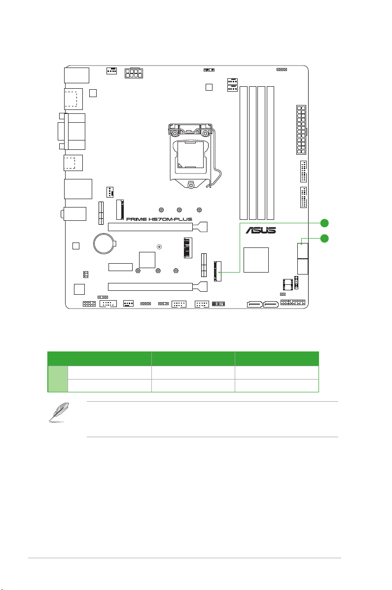
Connectors with shared bandwidth
KBMS_USB910
HDMI
DP
AIO_PUMP
ATX_12V
ASM
1442K
ADD_GEN 2_2
DIGI+
VRM
CPU_FAN
CPU_OPT
RGB_HEADER2
DVI
U32G2_1
U32G2_C2
LAN_U32G1_34
AUDIO
Ethernet
Audio
CODEC
AAFP
M.2_1(SOCKET3)
BATTERY
COM_DEBUG
SPDIF_OUT
IRST
SATA
PCIE
4.0 X4 CPU-attachedX
CHA_FAN1
COM
M.2_1(SOCKET3)
PCIEX1
CHA_FAN2
PCIEX16_1
Super
I/O
2280 2260 2242
PCIEX16_2
RGB_HEADER1
2230
ADD_GEN 2_1
LGA1200
2280
22602242
M.2(WIFI)
M.2_2(SOCKET3)
USBE12 USBE34
IRST
SATA
PCIE
3.0 X4 PCH-attachedV
M.2_2(SOCKET3)
TB_HEADER
DDR4 DIMM_B1 (64bit, 288-pin module)
DDR4 DIMM_B2* (64bit, 288-pin module)
DDR4 DIMM_A1 (64bit, 288-pin module)
®
Intel
H570
SATA6G_5SATA6G_6
Conguration 1 2
M.2_2 PCIe x4 SATA
A
SATA6G_2 V -
• The M.2_2 slot shares bandwidth with the SATA6G_2 port.
• When a device in SATA mode is installed on the M.2_2 socket, the SATA6G_2 port
cannot be used.
ATX_PWR
DDR4 DIMM_A2* (64bit, 288-pin module)
U32G1_78 U32G1_56
A
A
SATA6G_1
SATA6G_2SATA6G_4
SATA6G_3
128Mb
BIOS
TPM
64Mb
BIOS
CLRTC
PANEL
x
654 1 10 1124
Chapter 1: Product Introduction
Product Introduction
1
1.1 Before you proceed
Take note of the following precautions before you install motherboard components or change
any motherboard settings.
• Unplug the power cord from the wall socket before touching any component.
• Before handling components, use a grounded wrist strap or touch a safely grounded
object or a metal object, such as the power supply case, to avoid damaging them due
to static electricity.
• Before you install or remove any component, ensure that the ATX power supply is
switched off or the power cord is detached from the power supply. Failure to do so
may cause severe damage to the motherboard, peripherals, or components.
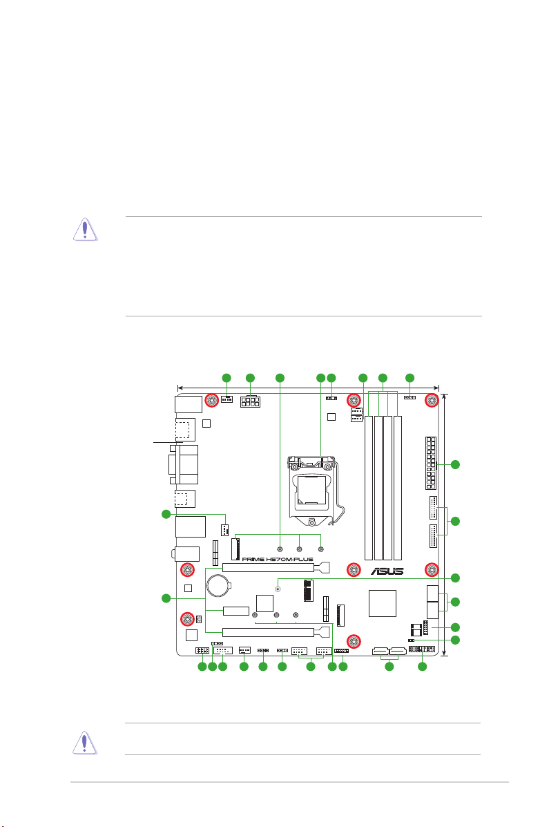
1.2 Motherboard overview
24.4cm(9.6in)
RGB_HEADER2
ATX_PWR
DDR4 DIMM_B1 (64bit, 288-pin module)
DDR4 DIMM_B2* (64bit, 288-pin module)
DDR4 DIMM_A1 (64bit, 288-pin module)
DDR4 DIMM_A2* (64bit, 288-pin module)
U32G1_78 U32G1_56
Intel
H570
®
SATA6G_1
SATA6G_3
128Mb
BIOS
TPM
64Mb
BIOS
CLRTC
PANEL
SATA6G_5SATA6G_6
187199 64 11 101314 16
SATA6G_2SATA6G_4
5
24.4cm(9.6in)
8
15
7
17
12
Place this
side towards
the rear of the
chassis
4
3
KBMS_USB910
HDMI
DP
DVI
U32G2_1
U32G2_C2
LAN_U32G1_34
AUDIO
Ethernet
Audio
CODEC
AAFP
ASM
1442K
COM_DEBUG
IRST
SATA
M.2_1(SOCKET3)
PCIE
4.0 X4 CPU-attachedX
BATTERY
SPDIF_OUT
AIO_PUMP
CHA_FAN1
COM
ATX_12V
M.2_1(SOCKET3)
PCIEX1
CHA_FAN2
PCIEX16_1
2230
Super
I/O
2280 2260 2242
PCIEX16_2
RGB_HEADER1
ADD_GEN 2_1
LGA1200
2280
22602242
M.2(WIFI)
USBE12 USBE34
ADD_GEN 2_2
DIGI+
VRM
IRST
SATA
M.2_2(SOCKET3)
PCIE
3.0 X4 PCH-attachedV
CPU_FAN
CPU_OPT
M.2_2(SOCKET3)
TB_HEADER
Unplug the power cord before installing or removing the motherboard. Failure to do so can
cause you physical injury and damage motherboard components.
ASUS PRIME H570M-PLUS
1-1
 Loading...