

Page 1
ASUS DL101
User Manual
E12914
Revised Edition V3
May 2017
15060-61410100
E12914_DL101_UM_V3.indd 1 5/24/2017 18:00:09
Page 2

COPYRIGHT INFORMATION
No part of this manual, including the products and software described in it, may be reproduced, transmitted,
transcribed, stored in a retrieval system, or translated into any language in any form or by any means, except
documentation kept by the purchaser for backup purposes, without the express written permission of ASUSTeK
COMPUTER INC. (“ASUS”).
ASUS PROVIDES THIS MANUAL “AS IS” WITHOUT WARRANTY OF ANY KIND, EITHER EXPRESS OR IMPLIED,
INCLUDING BUT NOT LIMITED TO THE IMPLIED WARRANTIES OR CONDITIONS OF MERCHANTABILITY OR FITNESS
FOR A PARTICULAR PURPOSE. IN NO EVENT SHALL ASUS, ITS DIRECTORS, OFFICERS, EMPLOYEES OR AGENTS BE
LIABLE FOR ANY INDIRECT, SPECIAL, INCIDENTAL, OR CONSEQUENTIAL DAMAGES (INCLUDING DAMAGES FOR
LOSS OF PROFITS, LOSS OF BUSINESS, LOSS OF USE OR DATA, INTERRUPTION OF BUSINESS AND THE LIKE), EVEN
IF ASUS HAS BEEN ADVISED OF THE POSSIBILITY OF SUCH DAMAGES ARISING FROM ANY DEFECT OR ERROR IN
THIS MANUAL OR PRODUCT.
Products and corporate names appearing in this manual may or may not be registered trademarks or
copyrights of their respective companies, and are used only for identication or explanation and to the owners’
benet, without intent to infringe.
SPECIFICATIONS AND INFORMATION CONTAINED IN THIS MANUAL ARE FURNISHED FOR INFORMATIONAL USE
ONLY, AND ARE SUBJECT TO CHANGE AT ANY TIME WITHOUT NOTICE, AND SHOULD NOT BE CONSTRUED AS A
COMMITMENT BY ASUS. ASUS ASSUMES NO RESPONSIBILITY OR LIABILITY FOR ANY ERRORS OR INACCURACIES
THAT MAY APPEAR IN THIS MANUAL, INCLUDING THE PRODUCTS AND SOFTWARE DESCRIBED IN IT.
Copyright © 2017 ASUSTeK COMPUTER INC. All Rights Reserved.
LIMITATION OF LIABILITY
Circumstances may arise where because of a default on ASUS’ part or other liability, you are entitled to recover
damages from ASUS. In each such instance, regardless of the basis on which you are entitled to claim damages
from ASUS, ASUS is liable for no more than damages for bodily injury (including death) and damage to real
property and tangible personal property; or any other actual and direct damages resulted from omission
or failure of performing legal duties under this Warranty Statement, up to the listed contract price of each
product.
ASUS will only be responsible for or indemnify you for loss, damages or claims based in contract, tort or
infringement under this Warranty Statement.
This limit also applies to ASUS’ suppliers and its reseller. It is the maximum for which ASUS, its suppliers, and
your reseller are collectively responsible.
UNDER NO CIRCUMSTANCES IS ASUS LIABLE FOR ANY OF THE FOLLOWING: (1) THIRD-PARTY CLAIMS AGAINST
YOU FOR DAMAGES; (2) LOSS OF, OR DAMAGE TO, YOUR RECORDS OR DATA; OR (3) SPECIAL, INCIDENTAL,
OR INDIRECT DAMAGES OR FOR ANY ECONOMIC CONSEQUENTIAL DAMAGES (INCLUDING LOST PROFITS OR
SAVINGS), EVEN IF ASUS, ITS SUPPLIERS OR YOUR RESELLER IS INFORMED OF THEIR POSSIBILITY.
SERVICE AND SUPPORT
Visit our multi-language web site at https://www.asus.com/support/
E12914_DL101_UM_V3.indd 2 5/24/2017 18:00:09
2
Page 3
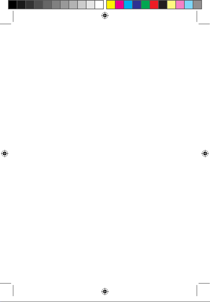
Table of Contents
Package contents ......................................................................................................4
Product overview.......................................................................................................5
Front View ..........................................................................................................................5
Back View ........................................................................................................................... 6
Alarm information .......................................................................................................... 8
Safety notices ................................................................................................................... 9
Getting started ...........................................................................................................10
Determining door status ..............................................................................................10
Preparing your door ...................................................................................................... 11
Installing your ASUS DL101 ........................................................................................ 14
Unlocking the ASUS DL101 ......................................................................................... 20
Locking the ASUS DL101 ............................................................................................. 23
Programming the ASUS DL101 .................................................................................25
Restoring to factory settings ...................................................................................... 31
Connecting to the ASUS Smart Home .................................................................... 32
Troubleshooting.........................................................................................................34
Drilling template (70 mm lockbolt) .....................................................................41
Drilling template (60 mm lockbolt) .....................................................................42
E12914_DL101_UM_V3.indd 3 5/24/2017 18:00:09
3
Page 4
Package contents
NOTE:
• Ifanyofthefollowingitemsaredamagedormissing,contact
your retailer.
• Theillustrateditemsbelowareforreferenceonly.
• Specicationssubjecttochangewithoutnotice.
OPEN
E12914_DL101_UM_V3.indd 4 5/24/2017 18:00:09
1 x ASUS DL101
exterior unit
1 x Deadbolt
1 x ASUS DL101
interior unit
1x Bag of screws
1 x ASUS DL101
interior unit cover
1 x Mounting plate
4
1 x Strike plate
2 x Keys
Page 5
Product overview
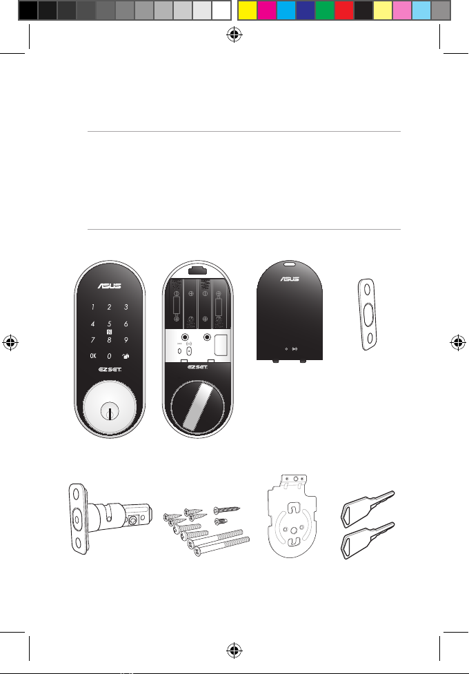
Front View
Touchscreen panel
Keyhole
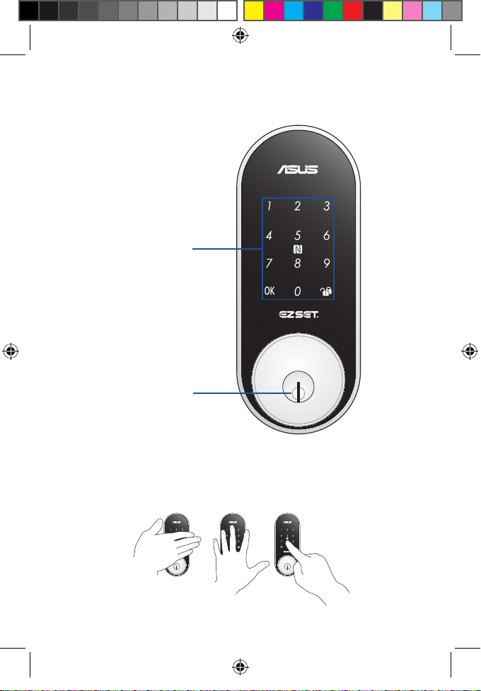
Use your palm to touch the touchscreen panel, or place your
nger on the NFC logo for at least 1 second to activate the
keypad.
E12914_DL101_UM_V3.indd 5 5/24/2017 18:00:09
5
Page 6
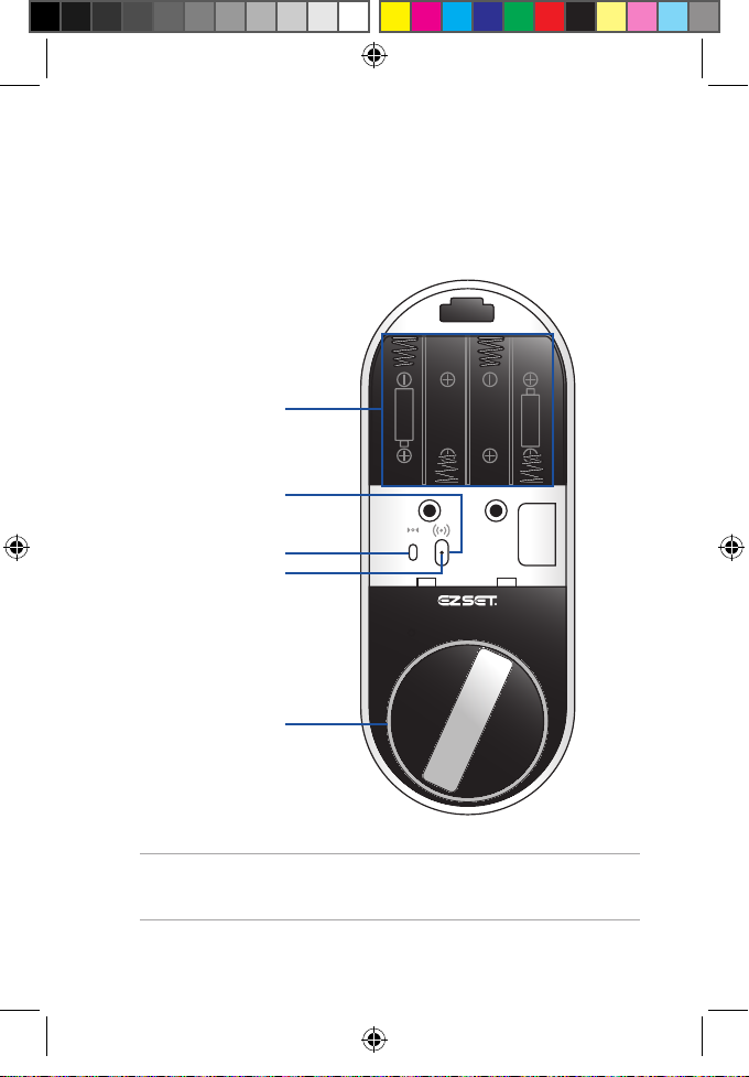
Back View
Battery compartment
Join button
Reset button
LED status indicator
Thumbturn lever
E12914_DL101_UM_V3.indd 6 5/24/2017 18:00:10
NOTE: Refer to LED information section for more details on the
LED status indicator.
6
Page 7
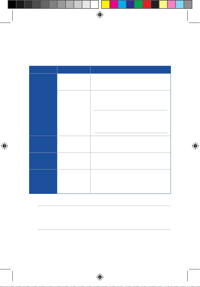
LED information
The LED status indicator helps identify the current status of
your ASUS DL101. Refer to the following table for details:
Color Status Description
Battery inserted
Solid Blue
Identifying
device
LED lights up for 2 seconds and the alarm
makes Do-Re-Mi sound
Use the companion app to identify which
device is connected to the gateway
NOTE: Ensure to connect your device
with the gateway before using this
feature through the companion app.
E12914_DL101_UM_V3.indd 7 5/24/2017 18:00:10
Blinking Blue
Solid Red
Blinking Red
Connecting
with gateway
Disconnected
with gateway
Low battery
warning
Press Join button for 1 second
(LED blinks for 5 seconds)
Press Join button for 5 seconds to reset
(LED lights up for 5 seconds)
A warning sound will go o when you
lock/unlock, and the LED will blink red in
1 second intervals until the touchscreen
panel goes o.
NOTE: The ASUS HG100 gateway is sold separately, some
features are only available after connecting with the ASUS
HG100 gateway.
7
Page 8

Alarm information
•
Short beep last for 0.1 second, long beep lasts for 0.5
second, both are at 85 dB.
•
Two short beeps indicates the operation is normal
or the setting is successful; one long beep indicates
abnormal operation or the setting is unsuccessful.
•
Three long beeps indicates that system protection has
been activated, the touchscreen panel will be locked for
2 minutes; low power warning.
•
Long beep for 30 seconds indicates anti-tamper
mechanism has been activated, use a password, user
card, or NFC phone to unlock.
•
Keypad sound is enabled by default, you can manually
set the sound to be enabled or disabled (refer to
Programming the ASUS DL101 for more details).
E12914_DL101_UM_V3.indd 8 5/24/2017 18:00:10
8
Page 9
Safety notices
•
Replace all batteries immediately when the low-battery
warning sounds.
•
DO NOT mix old batteries with new batteries, from
dierent brands, or alkaline and carbon-zinc batteries.
•
Insert the batteries according to the correct polarity.
•
DO NOT attempt to repair the product by yourself.
•
Change your codes regularly.
•
Minimize the exposure to moisture including wet hands
and direct contact with liquids.
•
Use soft, dry cloth to clean and avoid cleaning with
water, alcohol or other chemicals, or clean or maintain
with lubricants to prevent damage to the circuit board
or the surface coating.
•
DO NOT exert excessive force or use sharp objects on
the touchscreen panel.
• Usefour1.5VAAalkalinebatteriestomaintainastable
and long lasting power source.
• OnlyASUS-authorizedtechniciansshouldperform
repairs and maintenance for your device. Consult
an authorized ASUS service center for repairs and
maintenance.
E12914_DL101_UM_V3.indd 9 5/24/2017 18:00:10
9
Page 10
Getting started
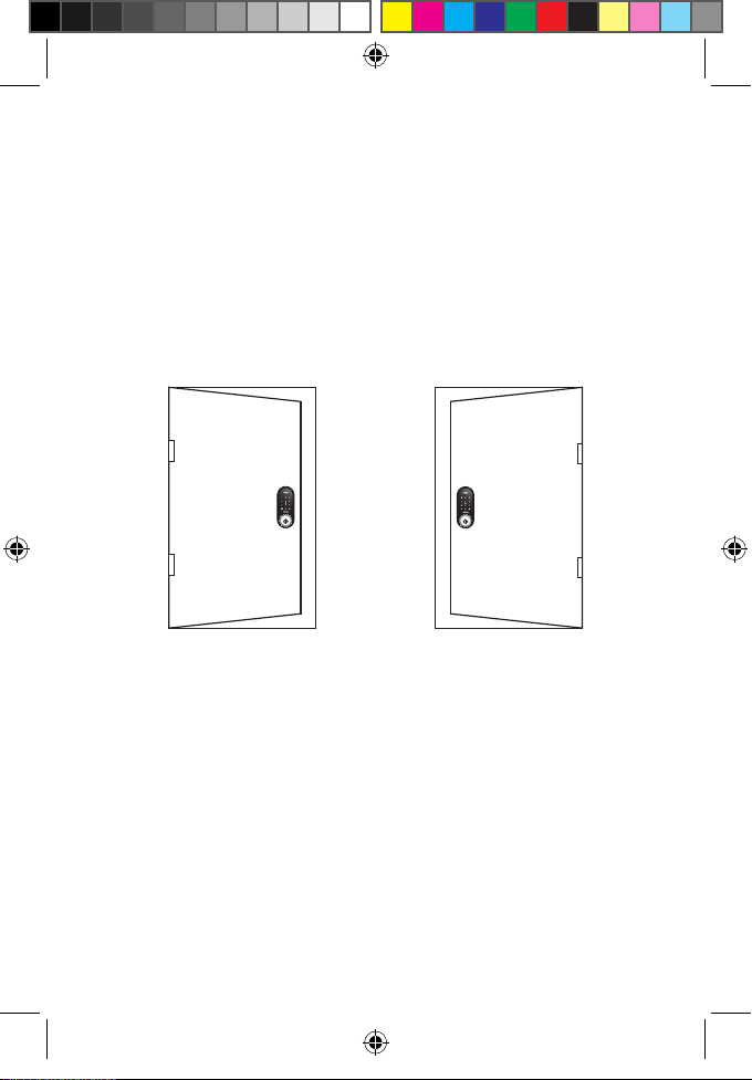
Determining door status
Take note of which direction your door will be opened before
installing your ASUS DL101, the orientation will be dierent
for left-handed doors and right-handed doors.
E12914_DL101_UM_V3.indd 10 5/24/2017 18:00:10
Left-handed door when
viewed from the outside.
Right-handed door when
viewed from the outside.
10
Page 11
Preparing your door
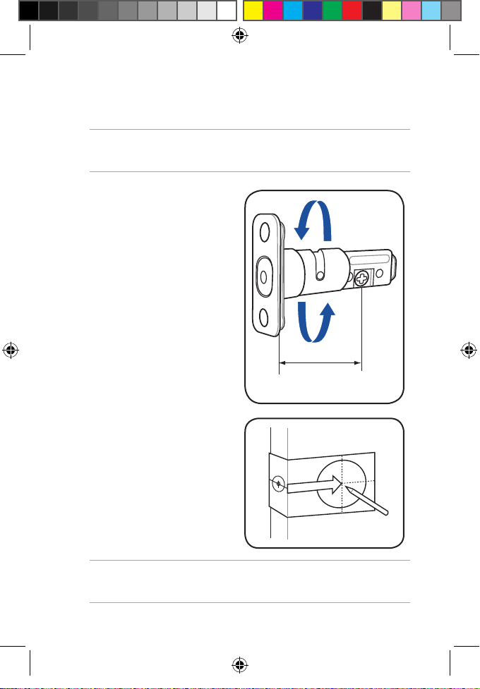
2 - 3/8”(60mm)
NOTE: The installation steps shown in this manual is for a lefthanded door and for reference only.
1. Adjust the lockbolt
length to t your
door by rotating it
clockwise or anticlockwise (this product
supports 60mm or
70mm conguration,
the illustration on
the right is the 60mm
conguration).
2. Attach the drilling
template to the door
and mark it with a pen.
E12914_DL101_UM_V3.indd 11 5/24/2017 18:00:10
NOTE: Use the Drilling template attached in the manual to help
mark the drilling location.
11
Page 12
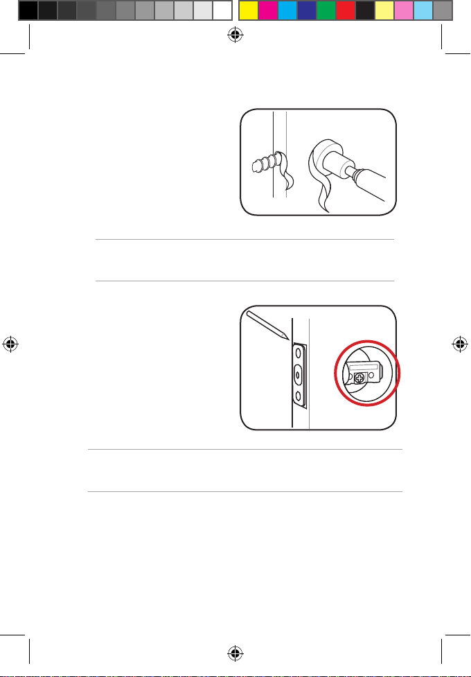
3. Drill the holes as
indicated on the
template.
NOTE: The location of the holes will vary per thickness of the
door.
4. Insert the deadbolt
into the door and
mark the face plate.
WARNING! The cross-shaped opening in the deadbolt should
be orientated at the bottom (see red circle area).
E12914_DL101_UM_V3.indd 12 5/24/2017 18:00:10
12
Page 13
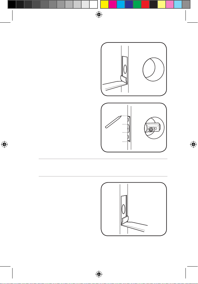
5. Chisel out a 4 mm
recess along the
marked lines.
6. Insert the deadbolt
again and close the
door, then mark the
door frame with the
lock bolt and the face
plate.
WARNING! The cross-shaped opening in the deadbolt should
be orientated at the bottom.
7. Chisel out a 2 mm
recess for the strike
plate along the marked
lines, then drill a hole
25.4 mm in diameter,
and 26 mm in depth
(enough for the locking
bolt).
E12914_DL101_UM_V3.indd 13 5/24/2017 18:00:10
13
Page 14

Installing your ASUS DL101
NOTE: The installation steps shown in this manual are for a left-
handed door and for reference only.
1. Insert the strike plate
into the door frame,
then secure it with the
bundled short screws.
2. Insert the deadbolt
into the door, then
secure it with the
bundled short screws.
E12914_DL101_UM_V3.indd 14 5/24/2017 18:00:10
14
Page 15

3. Insert the blade on the ASUS DL101 exterior unit
horizontally into the cross shaped opening on the
deadbolt, then pass the cable through the opening on
top of the deadbolt.
E12914_DL101_UM_V3.indd 15 5/24/2017 18:00:10
WARNING! Ensure the blade on the ASUS DL101 exterior unit is
horizontally inserted (see red circle area).
15
Page 16

4. Align the mounting plate and install it, then secure the
mounting plate with the bundled long screws.
NOTE: Ensure to pass the blade through the blade opening, and
pass the cable through the cable opening and place it on the
right side (see red circle area).
for metal doors
for wooden doors
E12914_DL101_UM_V3.indd 16 5/24/2017 18:00:11
16
Page 17

5. Insert a at head screwdriver into the opening with
the tip pointing slightly upwards, then gently tilt the
screwdriver upwards (as shown below) to release the
cover.
E12914_DL101_UM_V3.indd 17 5/24/2017 18:00:11
17
Page 18

6. Connect the cable of the exterior unit to the interior
OPEN
OPEN
unit, then align the interior unit and install it.
NOTE:
• Ensuretoconnectthecableinthecorrectorientation(black
to black and red to red), and placed at (A) as shown below
• Ensurethebladeishorizontallyalignedwiththethumbturn
lever as shown in (B) below.
• Ensurethatthethumbturnleverisintheopenposition.Turn
the thumbturn lever to make sure the lever turns the blade.
E12914_DL101_UM_V3.indd 18 5/24/2017 18:00:11
Right-handed doorLeft-handed door
18
Page 19

7. Secure the interior unit with the bundled screws, then
install four 1.5V AA batteries and the cover.
NOTE: Ensure the batteries are installed in the correct polarity.
E12914_DL101_UM_V3.indd 19 5/24/2017 18:00:11
19
Page 20

Setting lock direction
Enter master password (default:
0000) then press <OK>
NOTE: Set the lock direction after your ASUS DL101 is installed.
When the ASUS DL101 is unlocked, touch the panel, then press
<OK> to enter programming mode. This setting must be set up
after installing the ASUS DL101 for the rst time, and ensure the
thumbturn lever is installed correctly.
Press <0> then press <OK>
Unlocking the ASUS DL101
You can unlock the ASUS DL101 with a user password, one
time password (OTP), user card, key, or remotely through the
companion app.
When an incorrect password has been entered ve times, the
alarm in the ASUS DL101 will go o, the touchscreen panel
will be locked for two (2) minutes, and a warning message
will be sent to all the family members connected to the ASUS
HG 100.
The DL101 comes with an anti-tamper mechanism, and the
alarm in the ASUS DL101 will go o for thirty (30) seconds
when an intrusion has been detected. Use an user password,
user card, or the companion app to disable the alarm.
E12914_DL101_UM_V3.indd 20 5/24/2017 18:00:11
NOTE: Refer to Programming the ASUS DL101 section for more
details.
20
Page 21

Unlocking with a key
9
Insert your key
into the keyhole
Turn the key
Unlocking with a password
Touch the panel
Enter the random
code
NOTE: The two digit random code helps you spread ngerprint
across all the numbers, this is part of the ngerprint security
mechanism.
Enter user
password
Press
Unlocking with a user card or NFC phone
Touch the panel
NOTE: The two digit random code will appear when you touch
the panel but you do not need to enter it, touch the panel with
your user card or NFC phone to unlock directly.
Touch the panel with your user card
or NFC-enabled Android phone
E12914_DL101_UM_V3.indd 21 5/24/2017 18:00:11
21
Page 22

Unlocking with the companion app
Launch the ASUS
Smart Home
companion app
Navigate to the ASUS
DL101 device
Move the slider to
Unlock
NOTE: The companion app will show that the status of the
ASUS DL101 is Locked after locking. To unlock the ASUS DL101,
move the slider to Unlock.
E12914_DL101_UM_V3.indd 22 5/24/2017 18:00:12
22
Page 23

Locking the ASUS DL101
9
Locking with a key
Insert your key
into the keyhole
Turn the key
Locking with the touch panel
Touch the panel
Press
E12914_DL101_UM_V3.indd 23 5/24/2017 18:00:12
23
Page 24

Locking with the companion app
Launch the ASUS
Smart Home
companion app
Navigate to the ASUS
DL101 device
Move the slider to Lock
NOTE: The companion app will show that the status of the ASUS
DL101 is Unlocked after unlocking. To lock the ASUS DL101,
move the slider to Lock.
E12914_DL101_UM_V3.indd 24 5/24/2017 18:00:12
24
Page 25

Locking automatically
You can set the ASUS DL101 to automatically lock after it is
closed for thirty (30) seconds.
Enter master
password
(default: 0000)
then press <OK>
NOTE: This feature is disabled by default and is only available
after enabling it. When this feature is enabled, the ASUS DL101
automatically locks after it is closed for thirty (30) seconds. To
disable this feature, repeat these steps again.
Press <8> then
press <OK>
Programming the ASUS DL101
The ASUS DL101 can register one (1) master password and
nine (9) user passwords, one (1) OTP (one time password),
one (1) emergency password, nine (9) user card and NFCenabled android phone. You can also congure the settings
of the DL101 to suit your needs.
NOTE: All programming can only be performed when the ASUS
DL101 is unlocked. When the ASUS DL101 is unlocked, touch
the panel, then press <OK> to enter programming mode.
E12914_DL101_UM_V3.indd 25 5/24/2017 18:00:12
25
Page 26

Setting a new master password
Enter old master
password
(default: 0000)
then press <OK>
Press <1> then
press <OK>
Enter new master
password (four
to eight digits)
then press <OK>
NOTE: The master password is for programming the ASUS
DL101 only and cannot be used to unlock.
Setting a new user password
Enter master
password
(default: 0000)
then press <OK>
Press <2> then
press <OK>
Enter a new user
password (four
to eight digits)
then press <OK>
The panel will
repeat the
user password
sequentially then
press <OK>
Setting a new user card
Enter master
password
(default: 0000)
then press <OK>
Press <2> then
press <OK>
Touch the panel
with your user
card then press
<OK>
NOTE:
• Takenoteoftheslotyourusercardisshownonthepanel
when adding a new user card, this will help you delete the
correct slot in the future.
• TheASUSDL101supportsMIFARE,Felicasensorcards.
• RefertoSetting a new NFC-enabled Android phone section for
more details.
The panel will
show the slot
number this card
occupies then
press <OK>
E12914_DL101_UM_V3.indd 26 5/24/2017 18:00:12
26
Page 27

Setting a new NFC-enabled android phone
Enter master
password
(default: 0000)
then press <OK>
Press <2> then
press <OK>
Touch the panel
with your phone
then press <OK>
Panel will show
the slot number
this phone
occupies then
press <OK>
NOTE:
• NFCfunctiononAndroidsmartphonesvaryper
manufacturer, download the ASUS Smart Key app from
the Google Play Store to help set up your smart phone
with the ASUS DL101 and complete the NFC settings.
• Ensuretokeeptheappopenintheforegroundwhen
unlocking (some phones may limit apps in the background).
• VisittheASUSwebsitetoseeaQVL(qualiedvendorlist)of
compatible phones.
E12914_DL101_UM_V3.indd 27 5/24/2017 18:00:12
27
Page 28

Deleting an user card or NFC phone
Enter master
password
(default: 0000)
then press <OK>
Press <3> then
press <OK>
Enter the slot
number you
want to delete
then press <OK>
Deleting all user passwords, cards and NFC phones
Enter master
password
(default: 0000)
then press <OK>
Press <4> then
press <OK>
Setting an one time password (OTP)
Enter master
password
(default: 0000)
then press <OK>
Press <5> then
press <OK>
NOTE:
• YoucanonlyhaveoneOTPatatime.
• Theonetimepasswordcanonlybeusedonce,setanew
one time password if you need it again.
Enter OTP
password (four
to eight digits)
then press <OK>
E12914_DL101_UM_V3.indd 28 5/24/2017 18:00:12
28
Page 29

Setting an emergency password
Enter master
password
(default: 0000)
then press <OK>
Press <6> then
press <OK>
Enter emergency
password (four
to eight digits)
then press <OK>
NOTE:
• Youcanonlyhaveoneemergencypasswordatatime.
• Theemergencypasswordcannotbethesameastheuser
password or the one time password.
• Theemergencypasswordcanbeusedrepeatedly,youcan
change the emergency password if needed.
This feature can only be used with the ASUS HG100. The
ASUS HG100 helps the user in locking and unlocking
the ASUS DL101, and will send an “Door lock emergency
password has been activated” phone notication to all the
family members connected to the ASUS HG100 to alert of an
emergency.
WARNING! This feature can only be used with the ASUS HG100,
download and install the ASUS Smart Home app to use this
feature.
E12914_DL101_UM_V3.indd 29 5/24/2017 18:00:12
29
Page 30

Disabling the ASUS DL101 temporarily
Enter master password (default:
0000) then press <OK>
NOTE: When you disable the ASUS DL101, the ASUS DL101 can
only be unlocked by using the key or the companion app.
Press <7> then press <OK>
Disabling the electronic functions
Lock the ASUS DL101, then remove the
key halfway out of the keyhole, then
turn the key left or right and press for
about two (2) seconds. This will disable
all forms of electronic unlocking
(including password, user card, NFC
phone, and remotely unlocking).
NOTE:
• IfyouareconnectedwiththeASUSHG100,thisfeaturewill
automatically activate the panel protection mechanism, and
trigger connected alarm products.
• Whenthisfeatureisactivated,youcanonlyunlockusinga
key and cannot use the companion app to lock or unlock (you
can still check the lock status using the ASUS Smart Home
app).
• Thisfeatureisdisabledwhenyouuseakeytounlock.
E12914_DL101_UM_V3.indd 30 5/24/2017 18:00:12
30
Page 31

Enabling/Disabling keypad sound
Enter master password (default:
0000) then press <OK>
Press <9> then press <OK>
Restoring to factory settings
1. Locate the Reset button on your device.
2. Press and hold the Reset button for at about ve (5)
seconds until two beeps go o.
Low battery warning
• Whenyoureceivealowbatterywarning,pleasereplace
four AA alkaline batteries immediately.
Touch panel App
Low battery Normal
Super low
battery
Cannot be used
• Warningmethod:
1. After locking or unlocking, three long beeps will
go o, and the interior red LED will blink until the
panel goes o. If the power is too low, the panel
will not light up and only the warning will go o.
2.
A icon will be displayed in the app when the
power is low.
Can lock/unlock remotely, and display
low battery (in addition to the icon, a
warning will be sent to the phone)
No action can be executed, and will be
shown as oine (gray)
E12914_DL101_UM_V3.indd 31 5/24/2017 18:00:12
31
Page 32

• Yoursettingswillnotchangeorbeerasedwhenyour
battery completely dies.
• Youcanstilluseakeytolockorunlockwhenthebattery
completely dies.
Connecting to the ASUS Smart Home
1. Remove the cover on the interior unit.
2. Launch the ASUS Smart Home companion app.
3. Navigate to the Add Device screen (as shown below) on
your companion app, then tap Add Device.
E12914_DL101_UM_V3.indd 32 5/24/2017 18:00:13
4. Locate the LED indicator on the interior unit of your
ASUS DL101, then press it until it blinks blue.
32
Page 33

5. Tap Done once the ASUS DL101 has been added, then
follow the onscreen instructions to complete (refer to
the user manual of your ASUS Smart Home for more
details).
NOTE: Ensure that your device is within 45 meters of your ASUS
HG 100, and there are no obstructions such as thick solid walls
or other electronic devices that may cause interference.
E12914_DL101_UM_V3.indd 33 5/24/2017 18:00:13
33
Page 34

Troubleshooting
1. After installing and inserting batteries for the rst
time, pressing <OK> does not lock the door.
(short beep)
Problem: The lock direction is not set up yet.
Resolution: Ensure to set the lock direction rst after your ASUS
2. After installing and inserting batteries for the rst
time, there is no response when I press any key.
(no beep and no panel light)
Problem: The batteries are faulty or the cable is not in the
Resolution: Ensure the batteries are inserted in the correct
3. I cannot set the lock direction when setting up for
the rst time. (red LED light blinks three times, three
short beeps)
Problem: The lock direction in the memory is incorrect or
Resolution: Locate the Reset button and perform a factory
DL101 is installed.
correct orientation.
polarity and the cable is in the correct orientation.
dierent from the door (such as installing the lock to
a new door).
reset, then set the lock direction again.
E12914_DL101_UM_V3.indd 34 5/24/2017 18:00:13
34
Page 35

4. I can set the lock direction when setting up for the
rst time, but the door would not lock. (motor turns
slowly, lockbolt stuck, thumbturn lever jammed)
Problem: The batteries are low.
Resolution: Replace the batteries.
5. I can lock the door using a key, but I cannot unlock
the door when I enter my password.
(long beep)
Problem: The deadbolt is skew, or the lockbolt is misaligned
Resolution: Unlock the door with your keys, then adjust the
with the strike plate.
deadbolt and strike plate position so that the
locking bolt can smoothly pass through the opening
in the strike plate.
6. When the door is closed, pressing 9 locks the door,
the motor turns for a while but a long beep goes o.
When the door is open, pressing 9 locks the door,
and no beep goes o.
Problem: The hole for the locking bolt is not deep enough, or
Resolution: Drill the hole in the strike plate deep enough for the
the lockbolt is misaligned with the strike plate.
locking bolt (at least 2.5 mm), or adjust the strike
plate position.
E12914_DL101_UM_V3.indd 35 5/24/2017 18:00:13
35
Page 36

Federal Communications Commission Interference
Statement
This equipment has been tested and found to comply with the limits for a Class B digital
device, pursuant to part 15 of the FCC Rules. These limits are designed to provide reasonable
protection against harmful interference in a residential installation. This equipment generates,
uses and can radiate radio frequency energy and, if not installed and used in accordance with
the instructions, may cause harmful interference to radio communications. However, there is
no guarantee that interference will not occur in a particular installation. If this equipment does
cause harmful interference to radio or television reception, which can be determined by turning
the equipment off and on, the user is encouraged to try to correct the interference by one or
more of the following measures:
-Reorient or relocate the receiving antenna.
-Increase the separation between the equipment and receiver.
-Connect the equipment into an outlet on a circuit different from that to which the receiver is
connected.
-Consult the dealer or an experienced radio/ TV technician for help.
CAUTION!
Any changes or modications not expressly approved by the grantee
of this device could void the user’s authority to operate the equipment.
This device complies with Part 15 of the FCC Rules. Operation is subject to the following two
conditions: (1) this device may not cause harmful interference, and (2) this device must accept
any interference received, including interference that may cause undesired operation.
RF exposure warning
This equipment must be installed and operated in accordance with provided instructions and
the antenna(s) used for this transmitter must be installed to provide a separation distance of at
least 20 cm from all persons and must not be co-located or operating in conjunction with any
other antenna or transmitter. End-users and installers must be provide with antenna installation
instructions and transmitter operating conditions for satisfying RF exposure compliance.
E12914_DL101_UM_V3.indd 36 5/24/2017 18:00:13
36
Page 37

Canada, Industry Canada (IC) Notices
This device complies with Canada licence-exempt RSS standard(s).
Operation is subject to the following two conditions: (1) this device may not cause interference,
and (2) this device must accept any interference, including interference that may cause
undesired operation of the device.
Canada, avis d’Industry Canada (IC)
Cet appareil est conforme avec Industrie Canada exemptes de licence RSS standard(s).
Son fonctionnement est soumis aux deux conditions suivantes : (1) cet appareil ne doit pas
causer d’interférence et (2) cet appareil doit accepter toute interférence, notamment les
interférences qui peuvent affecter son fonctionnement.
Radio Frequency (RF) Exposure Information
The radiated output power of the Wireless Device is below the Industry Canada (IC) radio
frequency exposure limits. The Wireless Device should be used in such a manner such that the
potential for human contact during normal operation is minimized.
This device has also been evaluated and shown compliant with the IC RF Exposure limits under
mobile exposure conditions. (antennas are greater than 20cm from a person’s body).
Informations concernant l’exposition aux
fréquences radio (RF)
La puissance de sortie émise par l’appareil de sans l est inférieure à la limite d’exposition aux
fréquences radio d’Industry Canada (IC). Utilisez l’appareil de sans l de façon à minimiser les
contacts humains lors du fonctionnement normal.
Ce périphérique a également été évalué et démontré conforme aux limites d’exposition aux RF
d’IC dans des conditions d’exposition à des appareils mobiles (antennes sont supérieures à 20
cm à partir du corps d’une personne).
E12914_DL101_UM_V3.indd 37 5/24/2017 18:00:13
37
Page 38

Regional notice for California
WARNING!
cancer, birth defects or other reproductive harm. Wash hands after handling.
This product may contain chemicals known to the State of California to cause
ASUS Recycling/Takeback Services
ASUS recycling and takeback programs come from our commitment to the highest standards for
protecting our environment. We believe in providing solutions for you to be able to responsibly
recycle our products, batteries, other components as well as the packaging materials. Please
go to http://csr.asus.com/english/Takeback.htm for detailed recycling information in different
regions.
Regional notice for Singapore
E12914_DL101_UM_V3.indd 38 5/24/2017 18:00:13
Complies with
IMDA Standards
DB103778
This ASUS product complies with IMDA Standards.
38
Page 39

English ASUSTeK Computer Inc. hereby declares that this device is in compliance with the essential requirements and
other relevant provisions of related Directives. Full text of EU declaration of conformity is available at:
www.asus.com/support
Français AsusTek Computer Inc. déclare par la présente que cet appareil est conforme aux critères essentiels et autres
clauses pertinentes des directives concernées. La déclaration de conformité de l’UE peut être téléchargée à partir du site
Internet suivant : www.asus.com/support.
Deutsch ASUSTeK Computer Inc. erklärt hiermit, dass dieses Gerät mit den wesentlichen Anforderungen und anderen
relevanten Bestimmungen der zugehörigen Richtlinien übereinstimmt. Der gesamte Text der EU-Konformitätserklärung ist
verfügbar unter: www.asus.com/support
Italiano ASUSTeK Computer Inc. con la presente dichiara che questo dispositivo è conforme ai requisiti essenziali e alle
altre disposizioni pertinenti con le direttive correlate. Il testo completo della dichiarazione di conformità UE è disponibile
all’indirizzo: www.asus.com/support
Русский Компания ASUS заявляет, что это устройство соответствует основным требованиям и другим
соответствующим условиям соответствующих директив. Подробную информацию, пожалуйста, смотрите на
www.asus.com/support
Български С настоящото ASUSTeK Computer Inc. декларира, че това устройство е в съответствие със съществените
изисквания и другите приложими постановления на свързаните директиви. Пълният текст на декларацията за
съответствие на ЕС е достъпна на адрес:
Hrvatski ASUSTeK Computer Inc. ovim izjavljuje da je ovaj uređaj sukladan s bitnim zahtjevima i ostalim odgovarajućim
odredbama vezanih direktiva. Cijeli tekst EU izjave o sukladnosti dostupan je na: www.asus.com/support
Čeština Společnost ASUSTeK Computer Inc. tímto prohlašuje, že toto zařízení splňuje základní požadavky a další příslušná
ustanovení souvisejících směrnic. Plné znění prohlášení o shodě EU je k dispozici na adrese:
www.asus.com/support
Dansk ASUSTeK Computer Inc. erklærer hermed, at denne enhed er i overensstemmelse med hovedkravene og andre
relevante bestemmelser i de relaterede direktiver. Hele EU-overensstemmelseserklæringen kan ndes på:
www.asus.com/support
Nederlands ASUSTeK Computer Inc. verklaart hierbij dat dit apparaat voldoet aan de essentiële vereisten en andere
relevante bepalingen van de verwante richtlijnen. De volledige tekst van de EU-verklaring van conformiteit is beschikbaar
op: www.asus.com/support
Eesti Käesolevaga kinnitab ASUSTeK Computer Inc, et see seade vastab asjakohaste direktiivide oluliste nõuetele ja
teistele asjassepuutuvatele sätetele. EL vastavusdeklaratsiooni täielik tekst on saadaval järgmisel aadressil:
www.asus.com/support
Suomi ASUSTeK Computer Inc. ilmoittaa täten, että tämä laite on asiaankuuluvien direktiivien olennaisten vaatimusten ja
muiden tätä koskevien säädösten mukainen. EU-yhdenmukaisuusilmoituksen koko teksti on luettavissa osoitteessa:
www.asus.com/support
Ελληνικά Με το παρόν, η AsusTek Computer Inc. δηλώνει ότι αυτή η συσκευή συμμορφώνεται με τις θεμελιώδεις
απαιτήσεις και άλλες σχετικές διατάξεις των Οδηγιών της ΕΕ. Το πλήρες κείμενο της δήλωσης συμβατότητας είναι
διαθέσιμο στη διεύθυνση: www.asus.com/support
Magyar Az ASUSTeK Computer Inc. ezennel kijelenti, hogy ez az eszköz megfelel a kapcsolódó Irányelvek lényeges
követelményeinek és egyéb vonatkozó rendelkezéseinek. Az EU megfelelőségi nyilatkozat teljes szövege innen letölthető:
www.asus.com/support
Latviski ASUSTeK Computer Inc. ar šo paziņo, ka šī ierīce atbilst saistīto Direktīvu būtiskajām prasībām un citiem citiem
saistošajiem nosacījumiem. Pilns ES atbilstības paziņojuma teksts pieejams šeit: www.asus.com/support
Lietuvių „ASUSTeK Computer Inc.“ šiuo tvirtina, kad šis įrenginys atitinka pagrindinius reikalavimus ir kitas svarbias
susijusių direktyvų nuostatas. Visą ES atitikties deklaracijos tekstą galima rasti: www.asus.com/support
Norsk ASUSTeK Computer Inc. erklærer herved at denne enheten er i samsvar med hovedsaklige krav og andre relevante
forskrifter i relaterte direktiver. Fullstendig tekst for EU-samsvarserklæringen nnes på:
www.asus.com/support
Polski Firma ASUSTeK Computer Inc. niniejszym oświadcza, że urządzenie to jest zgodne z zasadniczymi wymogami
i innymi właściwymi postanowieniami powiązanych dyrektyw. Pełny tekst deklaracji zgodności UE jest dostępny pod
adresem: www.asus.com/support
Português A ASUSTeK Computer Inc. declara que este dispositivo está em conformidade com os requisitos essenciais e
outras disposições relevantes das Diretivas relacionadas. Texto integral da declaração da UE disponível em:
www.asus.com/support
www.asus.com/support
E12914_DL101_UM_V3.indd 39 5/24/2017 18:00:13
39
Page 40

Română ASUSTeK Computer Inc. declară că acest dispozitiv se conformează cerinţelor esenţiale şi altor prevederi
relevante ale directivelor conexe. Textul complet al declaraţiei de conformitate a Uniunii Europene se găseşte la:
www.asus.com/support
Srpski ASUSTeK Computer Inc. ovim izjavljuje da je ovaj uređaj u saglasnosti sa osnovnim zahtevima i drugim relevantnim
odredbama povezanih Direktiva. Pun tekst EU deklaracije o usaglašenosti je dostupan da adresi:
www.asus.com/support
Slovensky Spoločnosť ASUSTeK Computer Inc. týmto vyhlasuje, že toto zariadenie vyhovuje základným požiadavkám a
ostatým príslušným ustanoveniam príslušných smerníc. Celý text vyhlásenia o zhode pre štáty EÚ je dostupný na adrese:
www.asus.com/support
Slovenščina ASUSTeK Computer Inc. izjavlja, da je ta naprava skladna z bistvenimi zahtevami in drugimi ustreznimi
določbami povezanih direktiv. Celotno besedilo EU-izjave o skladnosti je na voljo na spletnem mestu:
www.asus.com/support
Español Por la presente, ASUSTeK Computer Inc. declara que este dispositivo cumple los requisitos básicos y otras
disposiciones pertinentes de las directivas relacionadas. El texto completo de la declaración de la UE de conformidad está
disponible en: www.asus.com/support
Svenska ASUSTeK Computer Inc. förklarar härmed att denna enhet överensstämmer med de grundläggande kraven och
andra relevanta föreskrifter i relaterade direktiv. Fulltext av EU-försäkran om överensstämmelse nns på:
www.asus.com/support
Українська ASUSTeK Computer Inc. заявляє, що цей пристрій відповідає основним вимогам та іншим відповідним
положенням відповідних Директив. Повний текст декларації відповідності стандартам ЄС доступний на:
www.asus.com/support
Türk çe AsusTek Computer Inc., bu aygıtın temel gereksinimlerle ve ilişkili Yönergelerin diğer ilgili koşullarıyla uyumlu
olduğunu beyan eder. AB uygunluk bildiriminin tam metni şu adreste bulunabilir: www.asus.com/support
Bosanski ASUSTeK Computer Inc. ovim izjavljuje da je ovaj uređaj usklađen sa bitnim zahtjevima i ostalim odgovarajućim
odredbama vezanih direktiva. Cijeli tekst EU izjave o usklađenosti dostupan je na: www.asus.com/support
E12914_DL101_UM_V3.indd 40 5/24/2017 18:00:13
Manufacturer ASUSTek COMPUTER INC.
Address, City 4F, No. 150, Li-Te Road, Peitou, Taipei 112,
Taiwan
Authorized
ASUS COMPUTER GmbH
Representative
in Europe
Address, City Harkort Str. 21-23, 40880 Ratingen
Country Germany
40
Page 41

Bore hole Ø54 mm (2-1/8”)
E12914_DL101_UM_V3.indd 41 5/24/2017 18:00:13
Drilling template (70 mm lockbolt)
Lockbolt length 70 mm (2-3/4”)
Cross bore hole
Ø25.4 mm (1”)
Fold along this line and align it
to the corner edge of the door.
The center of the cross bore hole
will vary per thickness of the door.
Page 42

to the corner edge of the door.
will vary per thickness of the door.
The center of the cross bore hole
Fold along this line and align it
Cross bore hole
Ø25.4 mm (1”)
Lockbolt length 60 mm (2-3/8”)
Drilling template (60 mm lockbolt)
E12914_DL101_UM_V3.indd 42 5/24/2017 18:00:13
Bore hole Ø54 mm (2-1/8”)
 Loading...