

Page 1

ASMB9-iKVM
Server Management Board
User Guide
E16160_ASMB9-iKVM_UM_V3.indb 1E16160_ASMB9-iKVM_UM_V3.indb 1 1/17/2020 2:29:19 PM1/17/2020 2:29:19 PM
Page 2

E16160
Revised Edition V3
January 2020
Copyright © 2020 ASUSTeK COMPUTER INC. All Rights Reserved.
No part of this manual, including the products and software described in it, may be reproduced, transmitted,
transcribed, stored in a retrieval system, or translated into any language in any form or by any means,
except documentation kept by the purchaser for backup purposes, without the express written permission
of ASUSTeK COMPUTER INC. (“ASUS”).
Product warranty or service will not be extended if: (1) the product is repaired, modified or altered, unless
such repair, modification of alteration is authorized in writing by ASUS; or (2) the serial number of the
product is defaced or missing.
ASUS PROVIDES THIS MANUAL “AS IS” WITHOUT WARRANTY OF ANY KIND, EITHER EXPRESS
OR IMPLIED, INCLUDING BUT NOT LIMITED TO THE IMPLIED WARRANTIES OR CONDITIONS OF
MERCHANTABILITY OR FITNESS FOR A PARTICULAR PURPOSE. IN NO EVENT SHALL ASUS, ITS
DIRECTORS, OFFICERS, EMPLOYEES OR AGENTS BE LIABLE FOR ANY INDIRECT, SPECIAL,
INCIDENTAL, OR CONSEQUENTIAL DAMAGES (INCLUDING DAMAGES FOR LOSS OF PROFITS,
LOSS OF BUSINESS, LOSS OF USE OR DATA, INTERRUPTION OF BUSINESS AND THE LIKE),
EVEN IF ASUS HAS BEEN ADVISED OF THE POSSIBILITY OF SUCH DAMAGES ARISING FROM ANY
DEFECT OR ERROR IN THIS MANUAL OR PRODUCT.
SPECIFICATIONS AND INFORMATION CONTAINED IN THIS MANUAL ARE FURNISHED FOR
INFORMATIONAL USE ONLY, AND ARE SUBJECT TO CHANGE AT ANY TIME WITHOUT NOTICE,
AND SHOULD NOT BE CONSTRUED AS A COMMITMENT BY ASUS. ASUS ASSUMES NO
RESPONSIBILITY OR LIABILITY FOR ANY ERRORS OR INACCURACIES THAT MAY APPEAR IN THIS
MANUAL, INCLUDING THE PRODUCTS AND SOFTWARE DESCRIBED IN IT.
Products and corporate names appearing in this manual may or may not be registered trademarks or
copyrights of their respective companies, and are used only for identification or explanation and to the
owners’ benefit, without intent to infringe.
ii
E16160_ASMB9-iKVM_UM_V3.indb 2E16160_ASMB9-iKVM_UM_V3.indb 2 1/17/2020 2:29:19 PM1/17/2020 2:29:19 PM
Page 3

Contents
Notices ...................................................................................................................... vii
Safety information ...................................................................................................... ix
About this guide .......................................................................................................... x
ASMB9-iKVM specifications summary.................................................................... xii
Chapter 1: Product Introduction
1.1 Welcome! .................................................................................................... 1-2
1.2 Package contents ......................................................................................1-2
1.3 Features ...................................................................................................... 1-3
1.4 System requirements .................................................................................1-4
1.5 Network setup ............................................................................................1-5
Chapter 2: Hardware Information
2.1 Before you proceed ...................................................................................2-2
2.2 Hardware installation ................................................................................. 2-2
2.3 Firmware update and IP configuration .....................................................2-3
2.3.1 Firmware update .........................................................................2-3
2.3.2 Configure BMC IP source static IP..............................................2-4
2.3.3 Configure BMC IP source DHCP ................................................2-5
2.4 BIOS configuration ....................................................................................2-6
2.4.1 Running the BIOS BMC configuration.........................................2-6
2.5 Server Mgmt menu ..................................................................................... 2-7
2.5.1 System Event Log .......................................................................2-8
2.5.2 BMC network configuration .........................................................2-9
2.5.3 View System Event Log ............................................................2-10
2.6 Running the ASMC8 utility ...................................................................... 2-11
2.6.1 Configuring the LAN controller ..................................................2-13
2.6.2 Configuring the user name and password ................................2-14
Chapter 3: Web-based User Interface
3.1 Web-based user interface .........................................................................3-2
3.1.1 Logging in the utility ....................................................................3-3
3.1.2 Using the utility ............................................................................3-3
3.2 Dashboard ..................................................................................................3-4
3.3 Sensor ......................................................................................................... 3-4
3.4 FRU Information ......................................................................................... 3-5
iii
E16160_ASMB9-iKVM_UM_V3.indb 3E16160_ASMB9-iKVM_UM_V3.indb 3 1/17/2020 2:29:19 PM1/17/2020 2:29:19 PM
Page 4

Contents
3.5 Logs & Reports ..........................................................................................3-5
3.5.1 IPMI Event Log............................................................................3-6
3.5.2 System Log .................................................................................3-7
3.5.3 Audit Log .....................................................................................3-8
3.5.4 Video Log ....................................................................................3-8
3.6 Settings ....................................................................................................... 3-9
3.6.1 Date & Time ................................................................................3-9
3.6.2 External User Services..............................................................3-10
3.6.3 KVM Mouse Setting ..................................................................3-11
3.6.4 Log Settings ..............................................................................3-11
3.6.5 Media Redirection Settings .......................................................3-12
3.6.6 Network Settings .......................................................................3-13
3.6.7 Platform Event Filters ..............................................................3-14
3.6.8 Services ....................................................................................3-15
3.6.9 SMTP ........................................................................................ 3-15
3.6.10 SSL Settings ............................................................................. 3-16
3.6.11 System Firewall ......................................................................... 3-17
3.6.12 User Management.....................................................................3-17
3.6.13 Video Recording........................................................................3-18
3.6.14 Web Server Instances ............................................................... 3-18
3.7 Remote Control ........................................................................................ 3-19
3.7.1 Console Redirection ..................................................................3-19
3.8 Image Redirection .................................................................................... 3-22
3.9 Power Control ...........................................................................................3-22
3.10 Maintenance .............................................................................................3-23
Chapter 4: Redfish Technology Pack
4.1 Redfish introduction .................................................................................. 4-2
4.2 Redfish API ................................................................................................. 4-3
4.2.1 Redfish API List...........................................................................4-3
4.2.2 Redfish API defnition...................................................................4-6
4.2.3 Requests ..................................................................................... 4-7
4.2.4 Responses .................................................................................. 4-9
4.3 Redfish Resources ...................................................................................4-11
4.3.1 ODATA properties .....................................................................4-11
4.3.2 User Configurable Properties ....................................................4-12
4.3.3 Resource ................................................................................... 4-12
4.3.4 Service Root..............................................................................4-16
iv
E16160_ASMB9-iKVM_UM_V3.indb 4E16160_ASMB9-iKVM_UM_V3.indb 4 1/17/2020 2:29:19 PM1/17/2020 2:29:19 PM
Page 5

Contents
4.3.5 Computer System Collection.....................................................4-18
4.3.6 Computer System .....................................................................4-19
4.3.7 Memory Collection ....................................................................4-31
4.3.8 Memory ..................................................................................... 4-32
4.3.9 ProcessorCollection .................................................................. 4-39
4.3.10 Processor .................................................................................. 4-40
4.3.11 Ethernet Interface Collection ..................................................... 4-43
4.3.12 EthernetInterface.......................................................................4-44
4.3.13 SimpleStorageCollection ........................................................... 4-51
4.3.14 SimpleStorage...........................................................................4-52
4.3.15 LogServiceCollection ................................................................ 4-53
4.3.16 Log Service ............................................................................... 4-54
4.3.17 LogEntryCollection .................................................................... 4-58
4.3.18 Log Entry ................................................................................... 4-59
4.3.19 VLAN Network Interface Collection ........................................... 4-62
4.3.20 VLANNetworkInterface..............................................................4-63
4.3.21 Chassis Collection.....................................................................4-64
4.3.22 Chassis .....................................................................................4-64
4.3.23 Power ........................................................................................ 4-70
4.3.24 Thermal ..................................................................................... 4-75
4.3.25 Manager Collection ................................................................... 4-78
4.3.26 Manager .................................................................................... 4-79
4.3.27 ManagerNetworkProtocol..........................................................4-84
4.3.28 SerialInterfaceCollection ........................................................... 4-88
4.3.29 SerialInterface ........................................................................... 4-88
4.3.30 VirtualMediaCollection .............................................................. 4-90
4.3.31 Account Service ........................................................................ 4-91
4.3.32 ManagerAccountCollection ....................................................... 4-93
4.3.33 Manager Account ...................................................................... 4-94
4.3.34 Role Collection .......................................................................... 4-96
4.3.35 Role ........................................................................................... 4-97
4.3.36 Event Service ............................................................................ 4-99
4.3.37 Event SubscriptionCollection .................................................. 4-102
4.3.38 Event Subscription .................................................................. 4-103
4.3.39 Task Service ........................................................................... 4-105
4.3.40 Task Collection........................................................................4-106
v
E16160_ASMB9-iKVM_UM_V3.indb 5E16160_ASMB9-iKVM_UM_V3.indb 5 1/17/2020 2:29:19 PM1/17/2020 2:29:19 PM
Page 6

Contents
4.3.41 Task ........................................................................................4-107
4.3.42 JSON Schema file collection ................................................... 4-109
4.3.43 JsonSchemaFile......................................................................4-109
4.3.44 SessionCollection....................................................................4-111
4.3.45 Session Service ...................................................................... 4-112
4.3.46 Session ...................................................................................4-113
4.3.47 Message Registry File Collection ............................................ 4-114
4.3.48 MessageRegistryFile...............................................................4-115
4.3.49 NetworkInterfaceCollection ..................................................... 4-116
4.3.50 NetworkAdapterCollection.......................................................4-116
4.3.51 NetworkAdapter ...................................................................... 4-116
4.3.52 Storage Collection ................................................................... 4-120
4.3.53 SecureBoot ............................................................................. 4-120
4.4 Redfish AMI OEM Entities ..................................................................... 4-122
4.4.1 Configurations ......................................................................... 4-122
4.4.2 PAM Configuration ..................................................................4-123
4.4.3 Manager Factory Reset – [DEBUG ONLY FEATURE] ........... 4-124
4.5 Known Limitations ................................................................................. 4-125
4.5.1 NULL Value .............................................................................4-125
4.5.2 GET Request BODY ...............................................................4-125
Appendix
A.1 LAN ports for server management .......................................................... A-2
A.2 Troubleshooting ........................................................................................ A-3
A.3 Sensor Table.............................................................................................. A-4
A.4 Redfish Assigned Privileges .................................................................. A-12
A.5 Redfish Reference documents .............................................................. A-14
Simplified EU Declaration of Conformity ............................................................ A-15
ASUS contact information .................................................................................... A-16
vi
E16160_ASMB9-iKVM_UM_V3.indb 6E16160_ASMB9-iKVM_UM_V3.indb 6 1/17/2020 2:29:19 PM1/17/2020 2:29:19 PM
Page 7

Notices
Federal Communications Commission Statement
This device complies with Part 15 of the FCC Rules. Operation is subject to the following two
conditions:
• This device may not cause harmful interference, and
• This device must accept any interference received including interference that may cause
undesired operation.
This equipment has been tested and found to comply with the limits for a Class B digital
device, pursuant to Part 15 of the FCC Rules. These limits are designed to provide
reasonable protection against harmful interference in a residential installation. This equipment
generates, uses and can radiate radio frequency energy and, if not installed and used
in accordance with manufacturer’s instructions, may cause harmful interference to radio
communications. However, there is no guarantee that interference will not occur in a particular
installation. If this equipment does cause harmful interference to radio or television reception,
which can be determined by turning the equipment off and on, the user is encouraged to try
to correct the interference by one or more of the following measures:
• Reorient or relocate the receiving antenna.
• Increase the separation between the equipment and receiver.
• Connect the equipment to an outlet on a circuit different from that to which the receiver is
connected.
• Consult the dealer or an experienced radio/TV technician for help.
The use of shielded cables for connection of the monitor to the graphics card is required
to assure compliance with FCC regulations. Changes or modifications to this unit not
expressly approved by the party responsible for compliance could void the user’s authority
to operate this equipment.
Compliance Statement of Innovation, Science and Economic
Development Canada (ISED)
This device complies with Innovation, Science and Economic Development Canada licence
exempt RSS standard(s). Operation is subject to the following two conditions: (1) this device
may not cause interference, and (2) this device must accept any interference, including
interference that may cause undesired operation of the device.
CAN ICES-3(B)/NMB-3(B)
Déclaration de conformité de Innovation, Sciences et
Développement économique Canada (ISED)
Le présent appareil est conforme aux CNR d’Innovation, Sciences et Développement
économique Canada applicables aux appareils radio exempts de licence. L’exploitation est
autorisée aux deux conditions suivantes : (1) l’appareil ne doit pas produire de brouillage,
et (2) l’utilisateur de l’appareil doit accepter tout brouillage radioélectrique subi, même si le
brouillage est susceptible d’en compromettre le fonctionnement.
CAN ICES-3(B)/NMB-3(B)
vii
E16160_ASMB9-iKVM_UM_V3.indb 7E16160_ASMB9-iKVM_UM_V3.indb 7 1/17/2020 2:29:19 PM1/17/2020 2:29:19 PM
Page 8

REACH
Complying with the REACH (Registration, Evaluation, Authorization, and Restriction of
Chemicals) regulatory framework, we published the chemical substances in our products at
ASUS website at http://csr.asus.com/english/REACH.htm.
ASUS Recycling/Takeback Services
ASUS recycling and takeback programs come from our commitment to the highest standards
for protecting our environment. We believe in providing solutions for you to be able to
responsibly recycle our products, batteries, other components as well as the packaging
materials. Please go to http://csr.asus.com/english/Takeback.htm for detailed recycling
information in different regions.
DO NOT
throw the motherboard in municipal waste. This product has been designed to
enable proper reuse of parts and recycling. This symbol of the crossed out wheeled bin
indicates that the product (electrical and electronic equipment) should not be placed in
municipal waste. Check local regulations for disposal of electronic products.
DO NOT
throw the mercury-containing button cell battery in municipal waste. This symbol
of the crossed out wheeled bin indicates that the battery should not be placed in municipal
waste.
viii
E16160_ASMB9-iKVM_UM_V3.indb 8E16160_ASMB9-iKVM_UM_V3.indb 8 1/17/2020 2:29:19 PM1/17/2020 2:29:19 PM
Page 9

Safety information
Electrical safety
• To prevent electrical shock hazard, disconnect the power cable from the electrical outlet
before relocating the server.
• When adding or removing devices to or from the server, ensure that the power cables
for the devices are unplugged before the signal cables are connected. If possible,
disconnect all power cables from the existing server before you add a device.
• Before connecting or removing signal cables from the server, ensure that all power
cables are unplugged.
• Seek professional assistance before using an adapter or extension cord. These devices
could interrupt the grounding circuit.
• Make sure that your power supply is set to the correct voltage in your area. If you are
not sure about the voltage of the electrical outlet you are using, contact your local power
company.
• If the power supply is broken, do not try to fix it by yourself. Contact a qualified service
technician or your retailer.
Operation safety
• Before installing any component to the server, carefully read all the manuals that came
with the package.
• Before using the product, make sure all cables are correctly connected and the power
cables are not damaged. If you detect any damage, contact your dealer immediately.
• To avoid short circuits, keep paper clips, screws, and staples away from connectors,
slots, sockets and circuitry.
• Avoid dust, humidity, and temperature extremes. Do not place the product in any area
where it may become wet.
• Place the product on a stable surface.
• If you encounter technical problems with the product, contact a qualified service
technician or your retailer.
ix
E16160_ASMB9-iKVM_UM_V3.indb 9E16160_ASMB9-iKVM_UM_V3.indb 9 1/17/2020 2:29:19 PM1/17/2020 2:29:19 PM
Page 10

About this guide
This user guide contains the information you need when installing and configuring the server
management board.
How this guide is organized
This guide contains the following parts:
• Chapter 1: Product Introduction
This chapter describes the server management board features and the new
technologies it supports.
• Chapter 2: Hardware Information
This chapter provides instructions on how to install the board to the server system and
install the utilities that the board supports.
• Chapter 3: Web-based user interface (ASMB9-iKVM only)
This chapter tells you how to use the web-based user interface that the server
management board supports.
• Chapter 4: Redfish Technology Pack
This chapter provides you with information on the Redfish APIs supported.
• Appendix
The Appendix shows the location of the LAN ports for server management and BMC
connector on server motherboards. This section also presents common problems that
you may encounter when installing or using the server management board.
Where to find more information
Refer to the following sources for additional information and for product and software updates.
1. ASUS websites
The ASUS website provides updated information on ASUS hardware and software
products. Refer to the ASUS contact information.
2. Optional documentation
Your product package may include optional documentation, such as warranty flyers,
that may have been added by your dealer. These documents are not part of the
standard package.
x
E16160_ASMB9-iKVM_UM_V3.indb 10E16160_ASMB9-iKVM_UM_V3.indb 10 1/17/2020 2:29:19 PM1/17/2020 2:29:19 PM
Page 11

Conventions used in this guide
To ensure that you perform certain tasks properly, take note of the following symbols used
throughout this manual.
DANGER/WARNING:
complete a task.
CAUTION:
complete a task.
IMPORTANT:
NOTE:
Typography
Bold text
Information to prevent damage to the components when trying to
Tips and additional information to help you complete a task.
Italics
<Key> Keys enclosed in the less-than and greater-than sign
<Key1> + <Key2> + <Key3> If you must press two or more keys simultaneously, the
Command
Information to prevent injury to yourself when trying to
Instructions that you MUST follow to complete a task.
Indicates a menu or an item to select.
Used to emphasize a word or a phrase.
means that you must press the enclosed key.
Example: <Enter> means that you must press the Enter
or Return key.
key names are linked with a plus sign (+).
Example: <Ctrl> + <Alt> + <Del>
Means that you must type the command exactly as
shown, then supply the required item or value enclosed
in brackets.
Example: At DOS prompt, type the command line:
format A:/S
xi
E16160_ASMB9-iKVM_UM_V3.indb 11E16160_ASMB9-iKVM_UM_V3.indb 11 1/17/2020 2:29:19 PM1/17/2020 2:29:19 PM
Page 12
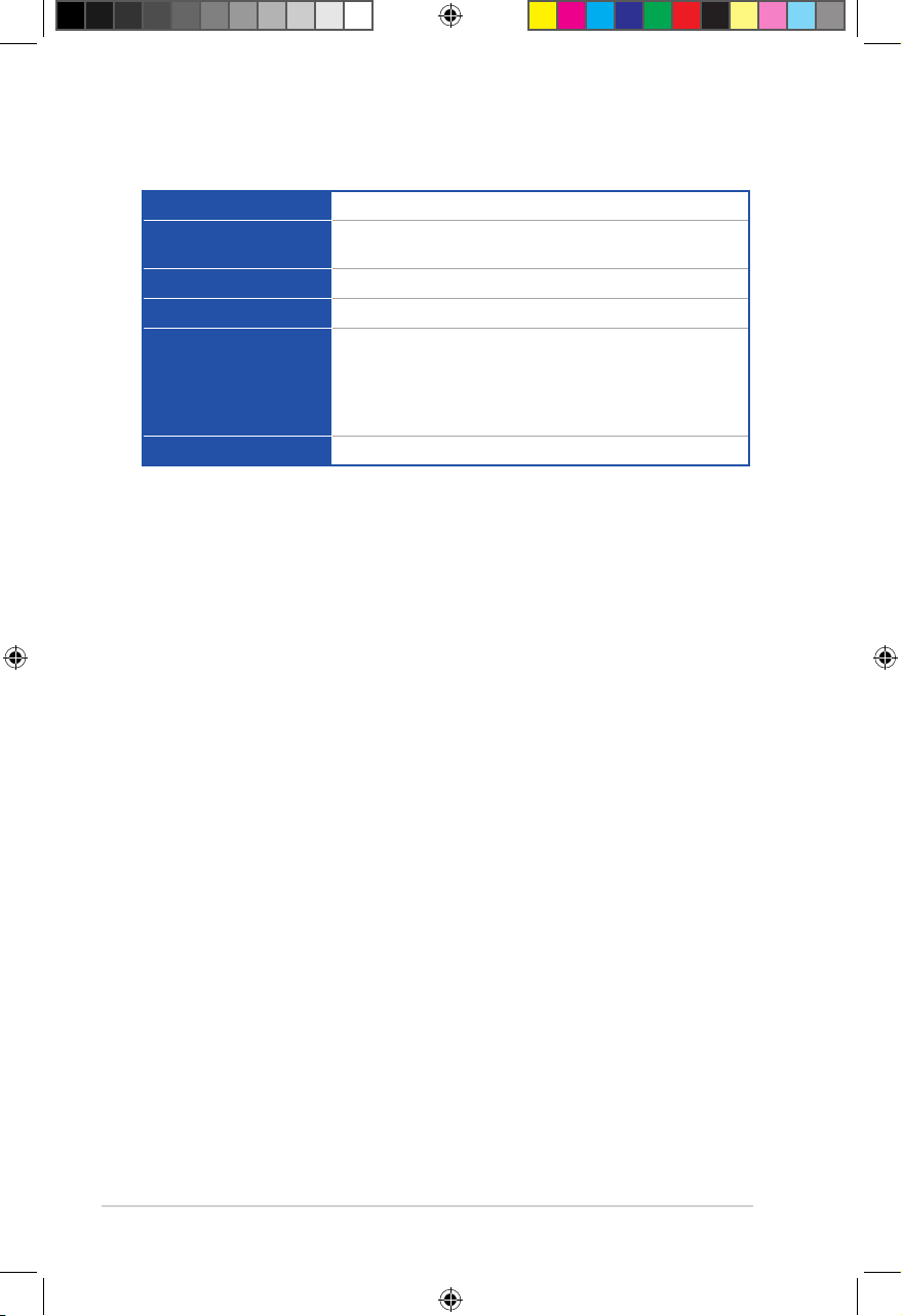
ASMB9-iKVM specifications summary
Chipset
Internal RAM
Aspeed 2500
384 MB for system
64 MB for video
Internal ROM
Timers
Main features
32 MB
32-bit Watchdog Timer
IPMI 2.0-compliant and supports
KVM over LAN
Web-based user interface (remote management)
Virtual media
Network Bonding support
Form factor
* Specifications are subject to change without notice.
22 mm x 17 mm
xii
E16160_ASMB9-iKVM_UM_V3.indb 12E16160_ASMB9-iKVM_UM_V3.indb 12 1/17/2020 2:29:19 PM1/17/2020 2:29:19 PM
Page 13

Chapter 1: Product Introduction
Product Introduction
This chapter describes the server management board features
and the new technologies it supports.
E16160_ASMB9-iKVM_UM_V3.indb 1E16160_ASMB9-iKVM_UM_V3.indb 1 1/17/2020 2:29:19 PM1/17/2020 2:29:19 PM
1
Page 14

Chapter 1: Product Introduction
1.1 Welcome!
Thank you for buying an ASUS ASMB9-iKVM server management board!
The ASUS ASMB9-iKVM is an Intelligent Platform Management Interface (IPMI) 2.0-compliant
board that allows you to monitor, control, and manage a remote server from the local
or central server in your local area network (LAN). With ASMB9-iKVM in your server
motherboard, you can completely and efficiently monitor your server in real-time. The solution
allows you to reduce IT management costs and increase the productivity.
Before you start installing the server management board, check the items in your package
with the list below.
1.2 Package contents
Check your server management board package for the following items.
• Support CD
• User guide
If any of the above items is damaged or missing, contact your retailer.
1-2
E16160_ASMB9-iKVM_UM_V3.indb 2E16160_ASMB9-iKVM_UM_V3.indb 2 1/17/2020 2:29:19 PM1/17/2020 2:29:19 PM
Page 15

ASUS ASMB9-iKVM
1.3 Features
1. IPMI 2.0
• System interface (KCS)
• LAN interface (supports RMCP+)
• System Event Log (SEL)
• Sensor Data Record (SDR)
• Field Replaceable Unit (FRU)
• Remote Power on/off, reboot
• Serial Over LAN (SOL)
• Authentication Type: RAKP-HMAC-SHA1
• Encryption (AES)
• Platform Event Filtering (PEF)
• Platform Event Trap (PET)
• Watchdog Timer
2. Private I2C Bus
• Auto monitoring sensors (temperature, voltage, fan speed and logging events)
3. PMBus*
• Supports power supply for PMBus device
4. PSMI*
• Supports power supply for PSMI bus device
5. Web-based GUI
• Monitor sensors; show SDR, SEL, FRU; configure BMC, LAN
• Supports SSL (HTTPS)
• Multiple user permission level
• Upgrade BMC firmware
• GUI remote management interface with web management capabilities (requires a
system that can display the Web-based GUI, a keyboard, and a mouse)
• SSH (Secure Shell)
• Allows up to 20 administrators to simultaneously perform remote maintenance
and recovery via the Web-based GUI during an operating system failure
• Remotely control and monitor your system over the web
• Supports Directory Integration – AD, LDAP
• Supports up to 2 administrators to simultaneously operate the remote server via
the Web-based GUI
6. Update Firmware
• DOS Tool
• Web GUI (Windows® XP/Vista/2003/2008, RHEL5.2, SLES10SP2)
1-3
E16160_ASMB9-iKVM_UM_V3.indb 3E16160_ASMB9-iKVM_UM_V3.indb 3 1/17/2020 2:29:19 PM1/17/2020 2:29:19 PM
Page 16

Chapter 1: Product Introduction
7. Notification
• PET
• SNMP Trap
• e-Mail
• Self diagnosing LED indicators to display hardware status
• Supports damage monitoring for CPU, RAM, storage device, etc.
8. KVM over Internet
• Web-based remote console
9. Remote Update BIOS
• Use Remote floppy to update BIOS
10. Remote Storage (Virtual Media)
• Support two remote storage for USB/CD-ROM/DVD and image
11. Remote Install OS
• Use remote storage to remote install OS
• Web-based GUI supports virtual drive, virtual directory, mounting ISO disc image
and remote installation
12. Supports SNMB MIB file
• A management information base (MIB) is a database used for managing the
entities in a communications network. Most often associated with the Simple
Network Management Protocol (SNMP).
13. User interface
• CIM
• SMASH-CLP
• WSMAN
* A power supply supported PMBus and PSMI is necessary.
** Specifications are subject to change without notice.
1.4 System requirements
Before you install the ASMB9-iKVM board, check if the remote server system meets the
following requirements:
• ASUS server motherboard with Baseboard Management Controller (BMC) connector*
• LAN (RJ-45) port for server management**
• Microsoft® Internet Explorer 5.5 or later; Firefox
* Visit www.asus.com for an updated list of server motherboards that support the
ASMB9-iKVM.
** See the Appendix for details.
1-4
E16160_ASMB9-iKVM_UM_V3.indb 4E16160_ASMB9-iKVM_UM_V3.indb 4 1/17/2020 2:29:20 PM1/17/2020 2:29:20 PM
Page 17
ASUS ASMB9-iKVM
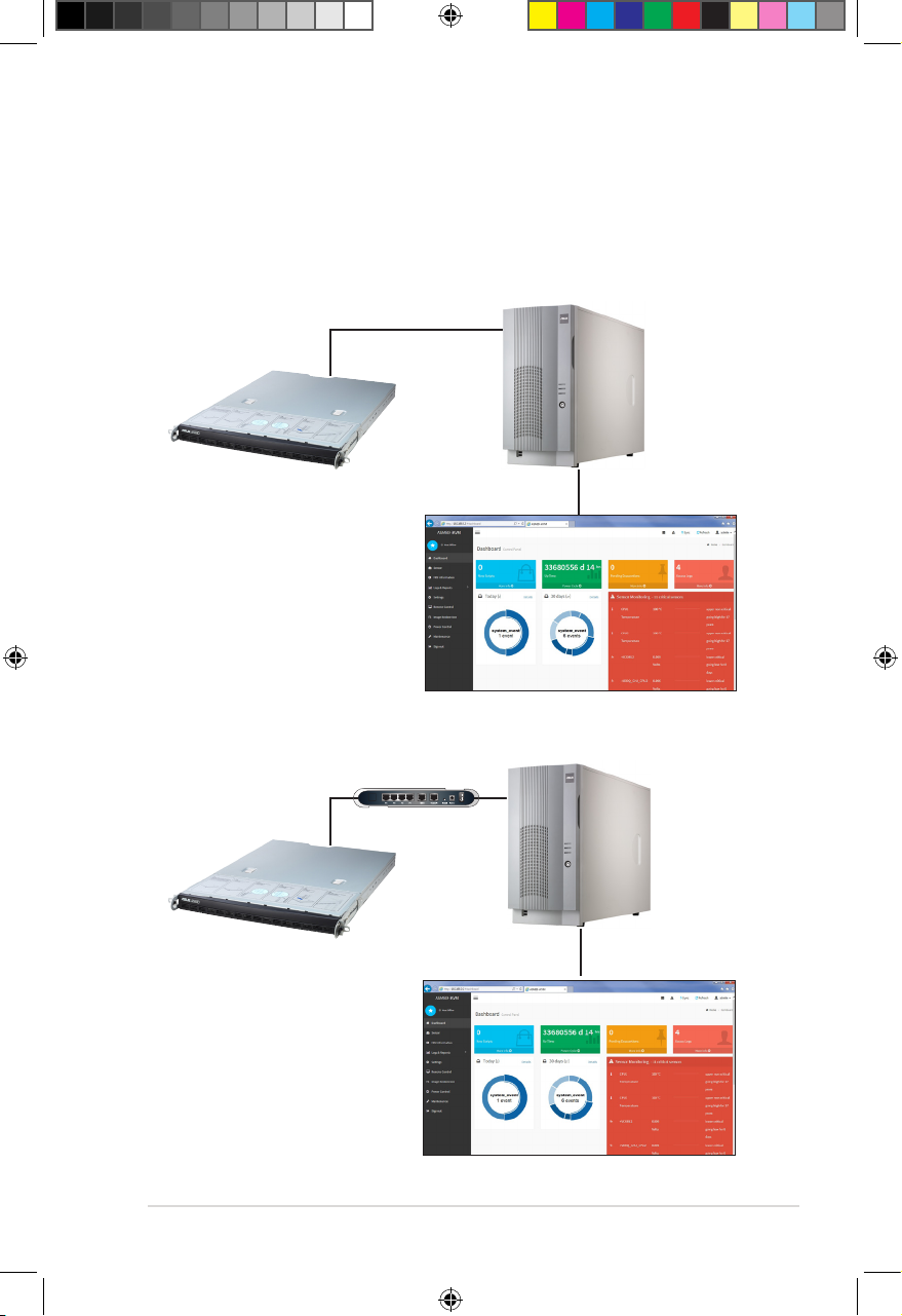
1.5 Network setup
The ASMB9-iKVM server management board installed on the remote server connects to
a local/central server via direct LAN connection or through a network hub. Below are the
supported server management configurations.
Direct LAN connection
RJ-45 cable
Remote server
with ASMB9-iKVM
LAN connection through a network hub
Hub or router
Remote server
with ASMB9-iKVM
Remote console with webbased browser
Remote console with webbased browser
1-5
E16160_ASMB9-iKVM_UM_V3.indb 5E16160_ASMB9-iKVM_UM_V3.indb 5 1/17/2020 2:29:20 PM1/17/2020 2:29:20 PM
Page 18

1-6
Chapter 1: Product Introduction
E16160_ASMB9-iKVM_UM_V3.indb 6E16160_ASMB9-iKVM_UM_V3.indb 6 1/17/2020 2:29:20 PM1/17/2020 2:29:20 PM
Page 19

Chapter 2: Hardware Information
Hardware Information
This chapter provides instructions on how to install the board to
the server system and install the utilities that the board supports.
E16160_ASMB9-iKVM_UM_V3.indb 1E16160_ASMB9-iKVM_UM_V3.indb 1 1/17/2020 2:29:20 PM1/17/2020 2:29:20 PM
2
Page 20

Chapter 2: Hardware Information
2.1 Before you proceed
Take note of the following precautions before you install the server management board to the
remote server system.
• Unplug the server system power cord from the wall socket before touching
any component.
• Use a grounded wrist strap or touch a safely grounded object or to a metal
object, such as the power supply case, before handling components to
avoid damaging them due to static electricity.
• Hold components by the edges to avoid touching the ICs on them.
• Whenever you uninstall any component, place it on a grounded antistatic
pad or in the bag that came with the component.
• Before you install or remove any component, ensure that the power supply
is switched off or the power cord is detached from the power supply. Failure
to do so may cause severe damage to the motherboard, peripherals, and/or
components.
2.2 Hardware installation
To set up the server system for server management:
1. Insert the LAN cable plug to the LAN port for server management.
Refer to the Appendix for the location of the LAN port for server management.
2. For direct LAN configuration, connect the other end of the LAN cable to the local/central
server LAN port.
For connection to a network hub or router, connect the other end of the LAN cable to
the network hub or router.
3. Ensure the VGA, USB, PS/2 cables are connected, then connect the power plug to a
grounded wall socket.
Every time after the AC power is re-plugged, you have to wait for about 70 seconds for the
system power up.
2-2
E16160_ASMB9-iKVM_UM_V3.indb 2E16160_ASMB9-iKVM_UM_V3.indb 2 1/17/2020 2:29:20 PM1/17/2020 2:29:20 PM
Page 21
ASUS ASMB9-iKVM
2.3 Firmware update and IP configuration
You need to update the ASMB9-iKVM firmware and configure IP source before you start
using the ASMB9-iKVM board.
2.3.1 Firmware update
To update the firmware:
1. Insert the support CD into the optical drive.
2. Restart the remote server then press <Del> during POST to enter the BIOS setup.
3. Go to the Boot menu and set the Boot Device Priority item to [CD-ROM].
4. When finished, press <F10> to save your changes and exit the BIOS setup.
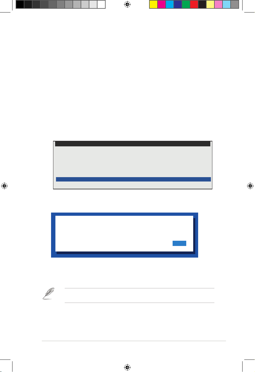
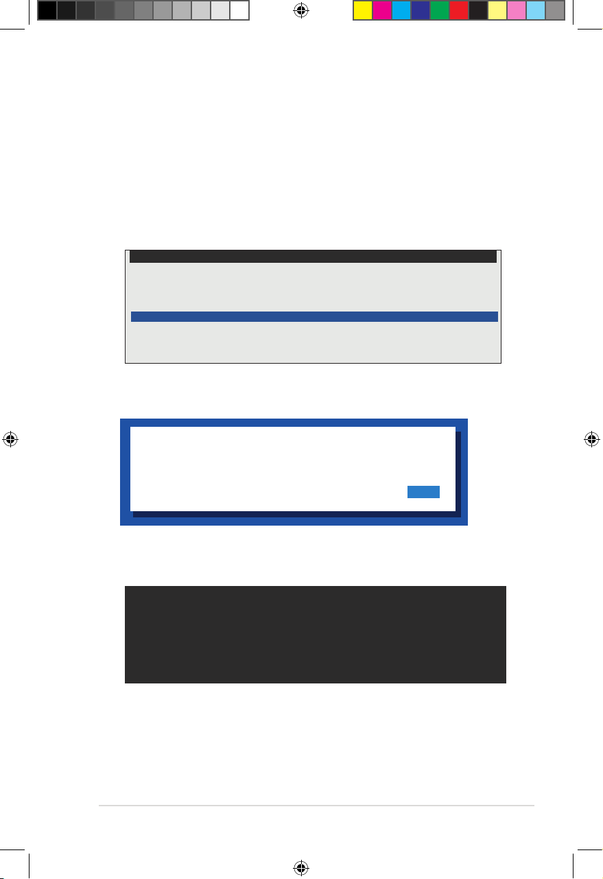
5. On reboot, select
main menu and press <Enter> to enter the sub-menu.
FreeDOS command prompt
Configure BMC IP Source Static IP for Shared LAN
Configure BMC IP Source DHCP IP for Shared LAN
Configure BMC IP Source Static IP for DM_LAN1
Configure BMC IP Source DHCP IP for DM_LAN1
ASMB9 Firnware Updated for Preserve Configuration (SDR, LAN, Username)
ASMB9 Firnware Updated for Clear Configuration (SDR, LAN, Username)
6. From the confirmation message, select <Yes> to update the firmware.
ASMB9-iKVM Firmware Update for Clear Configuration
ASUS Server Z11PP-D24 Series System
from the
WARNING !!!
UPDATE ASMB9 FIRMWARE NOW !
DO YOU WANT TO CONTINUE ?
No Yes
7. Wait for the firmware updating process to finish.
You may update the firmware from the web-based user interface. Refer to the
Maintenance
section for more information.
3.10
2-3
E16160_ASMB9-iKVM_UM_V3.indb 3E16160_ASMB9-iKVM_UM_V3.indb 3 1/17/2020 2:29:20 PM1/17/2020 2:29:20 PM
Page 22
Chapter 2: Hardware Information
2.3.2 Configure BMC IP source static IP
1. Insert the support CD into the optical drive.
2. Restart the remote server then press <Del> during POST to enter the BIOS setup.
3. Go to Boot menu and set the Boot Device Priority item to [CD-ROM].
4. When finished, press <F10> to save your changes and exit the BIOS setup.
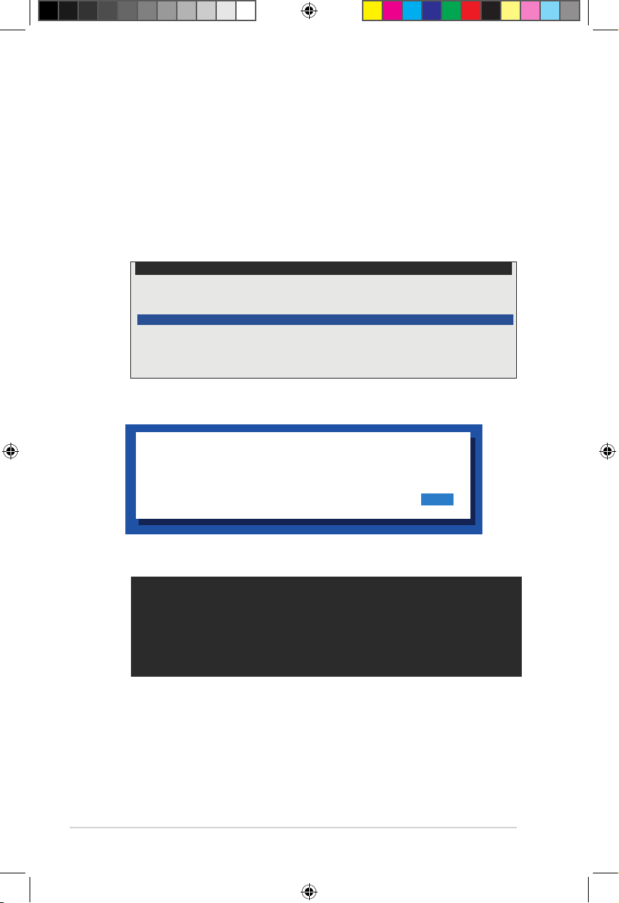
5. On reboot, select
from the main menu
FreeDOS command prompt
Configure BMC IP Source Static IP for Shared LAN
Configure BMC IP Source DHCP IP for Shared LAN
Configure BMC IP Source Static IP for DM_LAN1
Configure BMC IP Source DHCP IP for DM_LAN1
ASMB9 Firnware Update for Preserve Configuration (SDR, LAN, Username)
ASMB9 Firnware Update for Clear Configuration (SDR, LAN, Username)
6. Select <Yes> from the confirmation window.
WARNING !!!
CONFIGURE BMC IP Source STATIC IP NOW !
DO YOU WANT TO CONTINUE ?
Configure BMC IP Source Static IP for Shared LAN (or DM_LAN1)
and press <Enter> to enter the sub-menu.
ASUS Server Z11PP-D24 Series System
No Yes
7. Wait for the configuration to finish. When done, press any key to continue.
Detect: MotherBoard - > (Z11PP-D24 Series)
Detect: KCS Interface
New BMC IP Source : Static IP
Press any key to continue . . . _
8. Go to BIOS menu to set the IP. For more information, refer to the
configuration
2-4
menu section.
2.5.2 BMC network
E16160_ASMB9-iKVM_UM_V3.indb 4E16160_ASMB9-iKVM_UM_V3.indb 4 1/17/2020 2:29:21 PM1/17/2020 2:29:21 PM
Page 23
ASUS ASMB9-iKVM
2.3.3 Configure BMC IP source DHCP
1. Insert the support CD into the optical drive.
2. Restart the remote server then press <Del> during POST to enter the BIOS setup.
3. Go to Boot menu and set the Boot Device Priority item to [CD-ROM].
4. When finished, press <F10> to save your changes and exit the BIOS setup.
5. On reboot, select
the main menu and press <Enter> to enter the sub-menu.
FreeDOS command prompt
Configure BMC IP Source Static IP for Shared LAN
Configure BMC IP Source DHCP IP for Shared LAN
Configure BMC IP Source Static IP for DM_LAN1
Configure BMC IP Source DHCP IP for DM_LAN1
ASMB9 Firnware Update for Preserve Configuration (SDR, LAN, Username)
ASMB9 Firnware Update for Clear Configuration (SDR, LAN, Username)
6. Select <Yes> from the confirmation window.
WARNING !!!
CONFIGURE BMC IP Source DHCP NOW !
DO YOU WANT TO CONTINUE ?
Configure BMC IP Source DHCP for Shared LAN (or DM_LAN1)
ASUS Server Z11PP-D24 Series System
from
No Yes
7. Wait for the configuration to finish. When done, press any key to continue.
Detect: MotherBoard - > (Z11PP-D24 Series)
Detect: KCS Interface
New BMC IP Source : DHCP
Press any key to continue . . . _
8. The DHCP server will assign an IP for you.
2-5
E16160_ASMB9-iKVM_UM_V3.indb 5E16160_ASMB9-iKVM_UM_V3.indb 5 1/17/2020 2:29:21 PM1/17/2020 2:29:21 PM
Page 24

Chapter 2: Hardware Information
2.4 BIOS configuration
You need to adjust the settings in the BIOS setup of the remote server for correct
configuration and connection to the central server.
• Update the remote server BIOS file following the instructions in the motherboard/
system user guide. Visit the ASUS website (www.asus.com) to download the latest
BIOS file for the motherboard.
• The BIOS setup screens shown in this section are for reference purposes only, and
may not exactly match what you see on your screen.
2.4.1 Running the BIOS BMC configuration
To configure the BMC in the BIOS:
1. Restart the remote server, then press <Del> during POST to enter the BIOS setup.
2. Go to the
Server Mgmt
menu, then select the
Use this sub-menu to configure the BMC settings.
3. When finished, press <F10> to save your changes and exit the BIOS setup.
BMC network configuration
sub-menu.
2-6
E16160_ASMB9-iKVM_UM_V3.indb 6E16160_ASMB9-iKVM_UM_V3.indb 6 1/17/2020 2:29:21 PM1/17/2020 2:29:21 PM
Page 25
ASUS ASMB9-iKVM
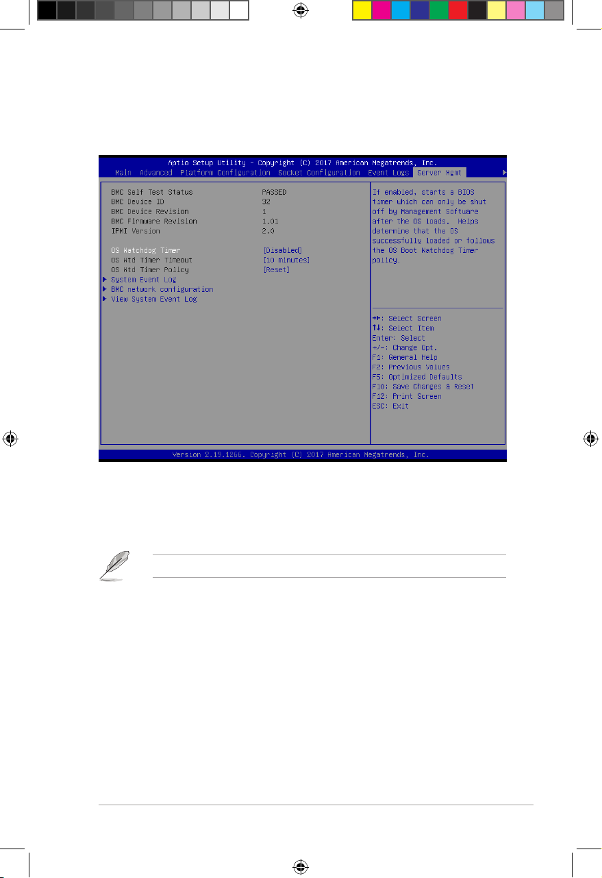
2.5 Server Mgmt menu
The Server Management menu displays the server management status and allows you to
change the settings.
OS Watchdog Timer [Disabled]
This item allows you to start a BIOS timer which can only be shut off by Intel Management
Software after the OS loads.
Configuration options: [Disabled] [Enabled]
The following items is configurable only when the
OS Watchdog Timer
is set to
[Enabled]
.
OS Wtd Timer Timeout [10 minutes]
Allows you to configure the length fo the OS Boot Watchdog Timer.
Configuration options: [5 minutes] [10 minutes] [15 minutes] [20 minutes]
OS Wtd Timer Policy [Reset]
This item allows you to configure the how the system should respond if the OS Boot
Watch Timer expires.
Configuration options: [Do Nothing] [Reset] [Power Down]
2-7
E16160_ASMB9-iKVM_UM_V3.indb 7E16160_ASMB9-iKVM_UM_V3.indb 7 1/17/2020 2:29:21 PM1/17/2020 2:29:21 PM
Page 26
Chapter 2: Hardware Information
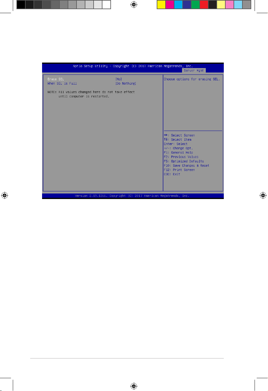
2.5.1 System Event Log
Allows you to change the SEL event log configuration.
Erase SEL [No]
Allows you to choose options for erasing SEL.
Configuration options: [No] [Yes, On next reset] [Yes, On every reset]
When SEL is Full [Do Nothing]
Allows you to choose options for reactions to a full SEL.
Configuration options: [Do Nothing] [Erase Immediately]
2-8
E16160_ASMB9-iKVM_UM_V3.indb 8E16160_ASMB9-iKVM_UM_V3.indb 8 1/17/2020 2:29:21 PM1/17/2020 2:29:21 PM
Page 27
ASUS ASMB9-iKVM
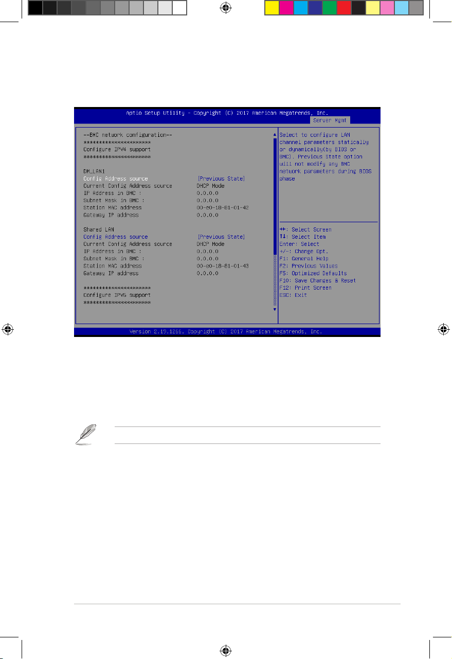
2.5.2 BMC network configuration
Allows you to set the BMC LAN parameter settings.
Configure IPV4 support
DM_LAN1 / Shared LAN
Config Address Source [Previous State]
Allows you to select the IP address source type. Set the LAN channel parameters
statically or dynamically.
Configuration options: [Previous State] [Static] [DynamicBmcDhcp]
The following items are available when you set
Config Address Source
to
[Static]
.
IP Address in BMC
Allows you to set the station IP address.
Subnet Mask in BMC
Allows you to set the subnet mask. We recommend that you use the same
Subnet Mask you have specified on the operating system network for the
used network card.
Gateway IP Address
Allows you to set the Gateway IP address.
2-9
E16160_ASMB9-iKVM_UM_V3.indb 9E16160_ASMB9-iKVM_UM_V3.indb 9 1/17/2020 2:29:21 PM1/17/2020 2:29:21 PM
Page 28
Chapter 2: Hardware Information
Configure IPV6 support
DM_LAN1 / Shared LAN
IPV6 support [Disabled]
Allows you to enable or disable IPV6 support.
Configuration options: [Enabled] [Disabled]
The following items are available when you set
IPV6 support
to [Enabled].
Config Address Source [Previous State]
Allows you to select the IP address source type. Set the LAN channel
parameters statically or dynamically.
Configuration options: [Previous State] [Static] [DynamicBmcDhcp]
The following items are available when you set
Config Address Source
to
[Static]
.
Station IPV6 address
Allows you to set the station IPV6 address.
Prefix Length
Allows you to set the prefix length.
IPV6 Router1 IP Address
Allows you to set the IPV6 Router1 IP address.
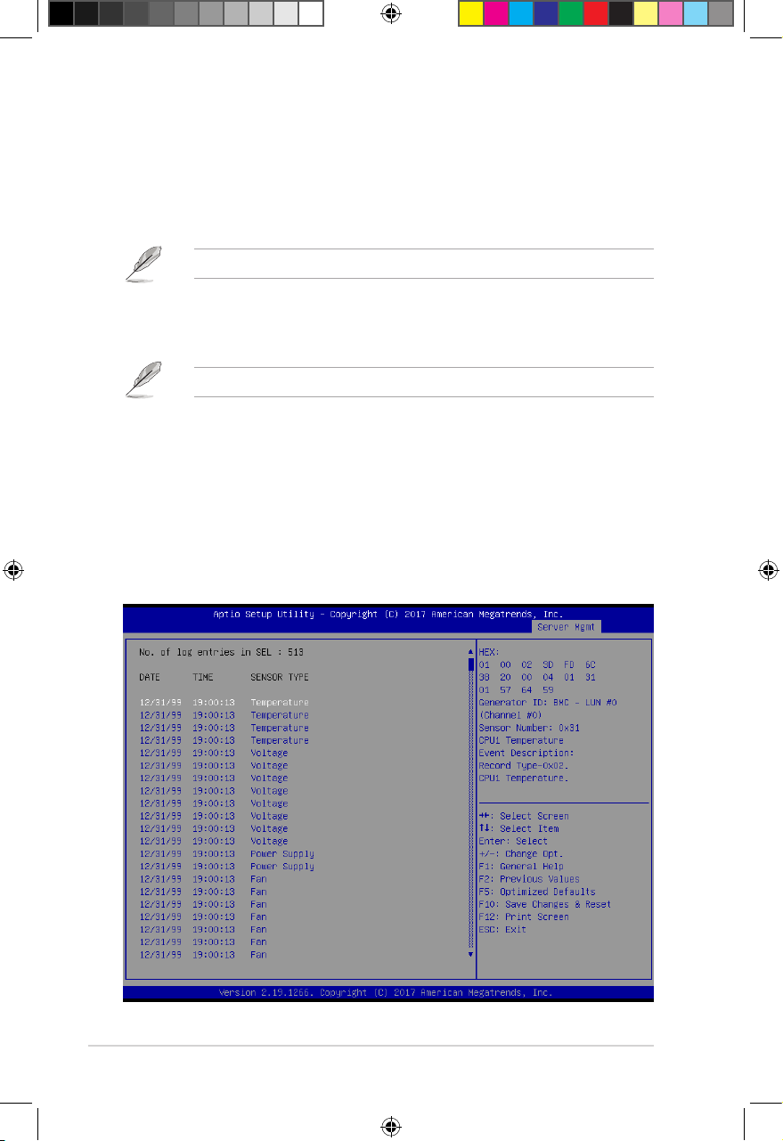
2.5.3 View System Event Log
Allows you to view all the events in the BMC event logs. It will take a maximum of 15 seconds
to read all the BMC SEL records.
2-10
E16160_ASMB9-iKVM_UM_V3.indb 10E16160_ASMB9-iKVM_UM_V3.indb 10 1/17/2020 2:29:21 PM1/17/2020 2:29:21 PM
Page 29

ASUS ASMB9-iKVM
2.6 Running the ASMC8 utility
The ASMC8 utility allows you to update the ASMB9-iKVM firmware, configure the LAN settings
for the remote server, and change the user name/password in DOS environment. This utility is
available from the support CD that came with the package.
To run the ASMC8 utility:
1. Insert the support CD into the optical drive.
2. Restart the remote server then press <Del> during POST to enter the BIOS setup.
3. Go to Boot menu and set the Boot Device Priority item to [CD-ROM].
4. When finished, press <F10> to save your changes and exit the BIOS setup.
5. On reboot, select
<Enter>.
FreeDOS command prompt
Configure BMC IP Source Static IP for Shared LAN
Configure BMC IP Source DHCP IP for Shared LAN
Configure BMC IP Source Static IP for DM_LAN1
Configure BMC IP Source DHCP IP for DM_LAN1
ASMB9 Firnware Update for Preserve Configuration (SDR, LAN, Username)
ASMB9 Firnware Update for Clear Configuration (SDR, LAN, Username)
FreeDOS command prompt
ASUS Server Z11PP-D24 Series System
from the main menu then press
6. From the
C:>
prompt, type
ASMC8 -?
then press <Enter> to display the ASMC8 Utility
Help Menu (as shown below).
+ - - - - - - - - - - - - - - - - - - - - - - - - - - - - - - - - - - - - - - - - - - - - - +
| ASUS Server Management card Utility 8.03 Help Menu |
+ - - - - - - - - - - - - - - - - - - - - - - - - - - - - - - - - - - - - - - - - - - - - - +
Usage:
ASMC8 -kcs[smic/bt/pci_smic] NetFn command data . . . .
ASMC8 -bmc_ip_source source[1:Static, 2:DHCP]
ASMC8 -bmc_ip ip_addr[10.10.10.20]
ASMC8 -bmc_mask ip_mask[255.255.255.0]
ASMC8 -bmc_gateway ip_addr[10.10.10.254]
ASMC8 -ipv6_source source[1:Static, 2:DHCP]
ASMC8 -ipv6 ipv6_addr[2001: 0db8 : 1234 : 5678 : 8769 : e1cb : aabb : ccdd]
ASMC8 -ipv6_prefix prefix_length[64]
ASMC8 -pet_ip_mac ip_addr[10.10.10.20] mac_addr[010203040506]
ASMC8 -bmc_ip_s_lan1 source[1:Static, 2:DHCP]
ASMC8 -bmc_ip_lan1 ip_addr[10.10.10.20]
ASMC8 -bmc_mask_lan1 ip_mask[255.255.255.0]
ASMC8 -bmc_g_lan1 ip_addr[10.10.10.254]
ASMC8 -ipv6_s_lan1 source[1:Static, 2:DHCP]
ASMC8 -ipv6_lan1 ip_addr[2001: 0db8 : 1234 : 5678 : 8769 : e1cb : aabb : ccdd]
ASMC8 -ipv6_prefix_lan1 prefix_length[64]
ASMC8 -pet_ip_m_lan1 ip_addr[10.10.10.20] mac_addr[010203040506]
<Press any key to see the next page> <ESC key to break>
Press any key to see next page.
2-11
E16160_ASMB9-iKVM_UM_V3.indb 11E16160_ASMB9-iKVM_UM_V3.indb 11 1/17/2020 2:29:21 PM1/17/2020 2:29:21 PM
Page 30

Chapter 2: Hardware Information
ASMC8 Help Menu options
Options Description
-kcs[smic/bt/pci_smic] NetFn command data....
-bmc_ip_source source[1: Static, 2: DHCP] Set the IP source
-bmc_ip [ip_addr]
(e.g., bmc_ip 10.10.10.20)
-bmc_mask [ip_mask]
(e.g., bmc_mask 255.255.255.0)
-bmc_gateway [ip_addr]
(e.g., bmc_gateway 10.10.10.254)
-pet_ip_mac [ip_addr] [mac_addr]
(e.g., pet_ip_mac 10.10.10.20 010203040506)
-bmc_ip_s_lan1 source[1: Static, 2: DHCP] Set the IP source for shared LAN
-bmc_ip_lan1 [ip_addr]
(e.g., bmc_ip 10.10.10.20)
-bmc_mask_lan1 [ip_mask]
(e.g., bmc_mask 255.255.255.0)
-bmc_g_lan1 [ip_addr]
(e.g., bmc_gateway 10.10.10.254)
-pet_ip_m_lan1 [ip_addr] [mac_addr]
(e.g., pet_ip_mac 10.10.10.20 010203040506)
-adm_name new_name_string Change the administration name
-user_name new_name_string Change the user name
-adm_password new_adm_password Change the administration password
-user_password new_user_password Change the user password
-sol_baud [baud rate]
(e.g., sol_baud 57600)
-bmc_info Displays the BMC and PET IP and
-fru -view fru_id Displays the system FRU information
-fru -load fru_file Update system FRU data from file
-fru -save fru_id fru_file Save system FRU data to file
-sel -clear Clear system event log
Send IPMI command
Write the BMC IP address for
dedicated LAN
Write the subnet mask for dedicated
LAN
Write the gateway address for
dedicated LAN
Write the PET destination IP and MAC
addresses for dedicated LAN
Write the BMC IP address for shared
LAN
Write the subnet mask for shared LAN
Write the gateway address for shared
LAN
Write the PET destination IP and MAC
addresses for shared LAN
Set the communication Baud rate
MAC addresses
2-12
E16160_ASMB9-iKVM_UM_V3.indb 12E16160_ASMB9-iKVM_UM_V3.indb 12 1/17/2020 2:29:21 PM1/17/2020 2:29:21 PM
Page 31

ASUS ASMB9-iKVM
2.6.1 Configuring the LAN controller
Before you can establish a connection to the ASMB9-iKVM board, you must configure the
LAN port for server management used by the remote server to connect to the local/central
server.
To configure the LAN port of the remote server:
1. Run the ASMC8 utility from the support CD following the instructions in the previous
section.
2. Set IP source:
a. Type
b. Type
3. Type
address to the remote server LAN port (if necessary). The screen displays the request
and response buffer.
When finished, the utility returns to the DOS prompt.
ASMC8 -bmc_ip_source 1
ASMC8 -bmc_ip_source 2
ASMC8 -bmc_ip xxx.xxx.xxx.xxx
Write the remote server IP address on a piece of paper for future reference.
c:\>ASMC8 -bmc_ip 10.10.10.243
Detect MotherBoard -> (Z11PP-D24 Series)
Detect KCS Interface
New BMC IP : 10.10.10.243
c:\>
Make sure that the assigned IP address for both remote and local/central servers are in the
same subnet. You can use the network settings utility in your OS to check.
if you want to set a static IP address.
if you want to get IP from DHCP server.
then press <Enter> to assign any IP
4. Configure your subnet mask and gateway address if necessary.
a. Type
ASMC8 -bmc_mask xxx.xxx.xxx.xxx
(your subnet mask encoded in
hexadecimal system)
b. Type
ASMC8 -bmc_gateway xxx.xxx.xxx.xxx
(your gateway address
encoded in hexadecimal system)
5. Restart the remote server, enter the BIOS setup, then boot from the hard disk drive.
6. Adjust the local/central server network settings, if necessary.
2-13
E16160_ASMB9-iKVM_UM_V3.indb 13E16160_ASMB9-iKVM_UM_V3.indb 13 1/17/2020 2:29:21 PM1/17/2020 2:29:21 PM
Page 32

Chapter 2: Hardware Information
2.6.2 Configuring the user name and password
You may change your user name and password from the ASMC8 utility.
To change the user name and password:
1. Insert the support CD into the optical drive.
2. Restart the remote server then press <Del> during POST to enter the BIOS setup.
3. Go to Boot menu and set the Boot Device Priority item to [CD-ROM].
4. When finished, press <F10> to save your changes and exit the BIOS setup.
5. On reboot, select
<Enter>.
6. From the
change the user name.
c:\>ASMC8 -user_name super
Detect MotherBoard -> (Z11PP-D24 Series)
Detect KCS Interface
Change User Name to super
c:\>
FreeDOS command prompt
C:>
prompt, type
ASMC8 -user_name xxxxx
from the main menu then press
then press <Enter> to
7. Type
ASMC8 -user_password xxxxxxxx
, then press <Enter> to change the
password.
8. Restart the remote server, enter the BIOS setup, then boot from the hard disk drive.
2-14
E16160_ASMB9-iKVM_UM_V3.indb 14E16160_ASMB9-iKVM_UM_V3.indb 14 1/17/2020 2:29:21 PM1/17/2020 2:29:21 PM
Page 33

Chapter 3: Web-based User Interface
Web-based User
Interface
This chapter tells you how to use the web-based user interface
that the server management board supports.
E16160_ASMB9-iKVM_UM_V3.indb 1E16160_ASMB9-iKVM_UM_V3.indb 1 1/17/2020 2:29:21 PM1/17/2020 2:29:21 PM
3
Page 34

Chapter 3: Web-based User Interface
3.1 Web-based user interface
The web-based user interface allows you to easily monitor the remote server’s hardware
information including temperatures, fan rotations, voltages, and power. This application also
lets you instantly power on/off or reset the remote server.
To enter the Web-based user interface:
1. Enter the BIOS Setup during POST.
2. Go to the Advanced Menu > Runtime Error Logging > CPU II0 Bridge
Configuration > Launch Storage OpROM, then press <Enter>.
3. Set Launch Storage OpROM to [Enabled].
4. Go to the Server Mgmt Menu > BMC network configuration > Configuration
Address source, then press <Enter>.
5. Enter the IP Address in BMC, Subnet Mask in BMC and Gateway Address in BMC.
6. Press <F10> to save your changes and exit the BIOS Setup.
You should install JRE on remote console first before using web-based management.
You can find
download JRE from
html
JRE
from the folder
http://www.oracle.com/technetwork/java/javase/downloads/index.
JAVA
of the ASMB9-iKVM support CD. You can also
3-2
E16160_ASMB9-iKVM_UM_V3.indb 2E16160_ASMB9-iKVM_UM_V3.indb 2 1/17/2020 2:29:22 PM1/17/2020 2:29:22 PM
Page 35

ASUS ASMB9-iKVM
3.1.1 Logging in the utility
1. Ensure that the LAN cable of the computer is connected to the LAN port of the remote
server.
2. Open the web browser and type in the same IP address as the one in the remote
server.
3. The below screen appears. Enter the default user name (admin) and password
(admin). Then click Login.
3.1.2 Using the utility
The web-based graphics user interface displays when you login in the utility successfully.
Click on a function from the list on the left hand side to start using its specific functions.
Function list
Toggle sync On/Off
Notifications received
Messages received
Content window
Reload current page
Account information
3-3
E16160_ASMB9-iKVM_UM_V3.indb 3E16160_ASMB9-iKVM_UM_V3.indb 3 1/17/2020 2:29:22 PM1/17/2020 2:29:22 PM
Page 36

Chapter 3: Web-based User Interface
3.2 Dashboard
The dashboard gives you a quick overview for all the system status, sensors, messages, and
logs. Click or hover your mouse over an item to see more details.
3.3 Sensor
The Sensor Readings page displays live readings for all the available sensors with details
like Sensor Name, Status, Current Reading and Behavior will be displayed. This page will
automatically refresh itself with data from the database. Please note that there may be some
delay when retrieving live data.
3-4
E16160_ASMB9-iKVM_UM_V3.indb 4E16160_ASMB9-iKVM_UM_V3.indb 4 1/17/2020 2:29:22 PM1/17/2020 2:29:22 PM
Page 37

ASUS ASMB9-iKVM
3.4 FRU Information
This Page displays the BMC’s FRU device information. The FRU page shows Basic
Information, Chassis Information, Board Information and Product Information of the FRU
device.
3.5 Logs & Reports
This menu contains the IPMI Event Log, System Log, Audit Log, and Video Log.
3-5
E16160_ASMB9-iKVM_UM_V3.indb 5E16160_ASMB9-iKVM_UM_V3.indb 5 1/17/2020 2:29:22 PM1/17/2020 2:29:22 PM
Page 38

Chapter 3: Web-based User Interface
3.5.1 IPMI Event Log
This page displays the list of events incurred by different sensors on this device. Click on a
record to see the details of that entry. You can click the
download the logs.
To view the Event Log on a selected time period
1. From the Filter By Date field, select the time period by selecting the Start Date and
the End Date from the calender.
2. From the Filter By Type field, select the type of event and sensor name to view the
events of the selected event type for that sensor.
Download Event Logs
button to
To clear all events from the list, click the
3-6
Clear Event Logs
button.
E16160_ASMB9-iKVM_UM_V3.indb 6E16160_ASMB9-iKVM_UM_V3.indb 6 1/17/2020 2:29:22 PM1/17/2020 2:29:22 PM
Page 39

ASUS ASMB9-iKVM
3.5.2 System Log
This page displays logs of system events for this device (if the options have been configured).
Logs have to be configured under
order to display any entries.
Settings
Log Settings
>
Advanced Log Settings
>
in
To view the System Log on a selected time period
1. From the Filter By Date field, select the time period by selecting the Start Date and
the End Date from the calender.
2. From the Event Category field, select the type of event to view the events of the
selected event type.
3-7
E16160_ASMB9-iKVM_UM_V3.indb 7E16160_ASMB9-iKVM_UM_V3.indb 7 1/17/2020 2:29:22 PM1/17/2020 2:29:22 PM
Page 40

Chapter 3: Web-based User Interface
3.5.3 Audit Log
This page displays logs of audit events for this device (if the options have been configured).
Logs have to be configured under
order to display any entries.
Settings
To view the Audit Log on a selected time period, from the
period by selecting the
Start Date
and the
End Date
Log Settings
>
Advanced Log Settings
>
Filter By Date
from the calender.
in
field, select the time
3.5.4 Video Log
This page displays logs of available recorded video files (if the options have been configured).
Logs have to be configured under
order to display any entries.
Settings
Log Settings
>
Advanced Log Settings
>
in
To view the Video Log on a selected time period, from the
period by selecting the
3-8
Start Date
and the
End Date
Filter By Date
from the calender.
field, select the time
E16160_ASMB9-iKVM_UM_V3.indb 8E16160_ASMB9-iKVM_UM_V3.indb 8 1/17/2020 2:29:22 PM1/17/2020 2:29:22 PM
Page 41

ASUS ASMB9-iKVM
3.6 Settings
This page allows you to configure the BMC settings. Click on an item for more options.
3.6.1 Date & Time
This page allows you to set the date and time on the BMC.
3-9
E16160_ASMB9-iKVM_UM_V3.indb 9E16160_ASMB9-iKVM_UM_V3.indb 9 1/17/2020 2:29:22 PM1/17/2020 2:29:22 PM
Page 42

Chapter 3: Web-based User Interface
3.6.2 External User Services
This page allows you to set the LDAP/E-directory Settings, Active directory Settings, and
RADIUS Settings.
LDAP/E-directory Settings
This page allows you to set the LDAP/E-directory Settings. The
Access Protocol (LDAP)
directory services implemented in Internet Protocol (IP) networks. If you have an LDAP server
configured on your network, you can use it as an easy way to add, manage and authenticate
MegaRAC® card users. This is done by passing login requests to your LDAP Server. This
means that there is no need to define an additional authentication mechanism, when using
the MegaRAC® card. Since your existing LDAP Server keeps an authentication centralized,
you will always know who is accessing the network resources and can easily define the user
or group-based policies to control access.
is an application protocol for querying and modifying data of
Lightweight Directory
Active directory Settings
This page allows you to set the Active directory Settings. An active directory does a variety
of function including the ability to provide the information on objects, helps organize these
objects for easy retrieval and access, allows access by users and administrators, and allows
the administrators to set security up for the directory.
RADIUS Settings
This page is used to enable or disable RADIUS authentication and enter the required
information to access the RADIUS server.
3-10
E16160_ASMB9-iKVM_UM_V3.indb 10E16160_ASMB9-iKVM_UM_V3.indb 10 1/17/2020 2:29:22 PM1/17/2020 2:29:22 PM
Page 43

ASUS ASMB9-iKVM
3.6.3 KVM Mouse Setting
This page allows you to set the mouse mode. The Redirection Console handles mouse
emulation from local window to remote screen using either of the three methods. Only the
Administrator has the right to configure this option.
3.6.4 Log Settings
This page allows you to set the log policy for the event log.
Log Settings Policy
This page is used to configure the log policy for the event log
Advanced Log Settings
This page allows you to set advanced settings for the event logs.
3-11
E16160_ASMB9-iKVM_UM_V3.indb 11E16160_ASMB9-iKVM_UM_V3.indb 11 1/17/2020 2:29:22 PM1/17/2020 2:29:22 PM
Page 44

Chapter 3: Web-based User Interface
3.6.5 Media Redirection Settings
This page allows you to set the media redirection settings.
General Settings
This page allows you to enable or disable Local Media support, check or uncheck the
checkbox respectively.
VMedia Instance Settings
This page allows you to configure settings for media devices.
Remote Session
This page allows you to change the settings for the remote session.
3-12
E16160_ASMB9-iKVM_UM_V3.indb 12E16160_ASMB9-iKVM_UM_V3.indb 12 1/17/2020 2:29:23 PM1/17/2020 2:29:23 PM
Page 45

ASUS ASMB9-iKVM
3.6.6 Network Settings
The Network Settings page allows you to configure the network settings.
Network IP Settings
This page allows you to manage LAN support for the interface.
Network Bond Configuration
This page allows you to enable network bonding for network interfaces.
DNS Configuration
This page allows you to manage DNS settings of the device.
3-13
E16160_ASMB9-iKVM_UM_V3.indb 13E16160_ASMB9-iKVM_UM_V3.indb 13 1/17/2020 2:29:23 PM1/17/2020 2:29:23 PM
Page 46

Chapter 3: Web-based User Interface
3.6.7 Platform Event Filters
Platform Event Filtering (PEF)
selected actions on event messages that it receives or has internally generated. These
actions include operations such as system power-off, system reset, as well as triggering the
generation of an alert. A PEF implementation is recommended to provide at least 16 entries
in the event filter table. A subset of these entries should be pre-configured for common
system failure events, such as over-temperature, power system failure, fan failure events, etc.
Event Filters
This page shows all configured Event filters and available slots. You can modify or add new
event filter entry on this page. By default,15 event filter entries are configured among the 40
available slots.
provides a mechanism for configuring the BMC to take
Alert Policies
This page shows all configured Alert policies and available slots. You can modify or add new
alert policy entry from on this page. A maximum of 60 slots are available.
LAN Destinations
This page shows all configured LAN destinations and available slots. You can modify or add
new LAN destination entry from on this page. A maximum of 15 slots are available.
3-14
E16160_ASMB9-iKVM_UM_V3.indb 14E16160_ASMB9-iKVM_UM_V3.indb 14 1/17/2020 2:29:23 PM1/17/2020 2:29:23 PM
Page 47

ASUS ASMB9-iKVM
3.6.8 Services
This page lists services running on the BMC. It shows current status and other basic
information about the services.
3.6.9 SMTP
The SMTP page allows you to configure SMTP mail server.
3-15
E16160_ASMB9-iKVM_UM_V3.indb 15E16160_ASMB9-iKVM_UM_V3.indb 15 1/17/2020 2:29:23 PM1/17/2020 2:29:23 PM
Page 48

Chapter 3: Web-based User Interface
3.6.10 SSL Settings
Secure Socket Layer
The
between web servers and browsers. The protocol uses a third party, a
(CA)
, to identify one end or both end of the transactions.
View SSL Certificate
This page displays the basic information about the uploaded SSL certificate.
protocol was created by Netscape to ensure secure transactions
Certificate Authority
Generate SSL Certificate
This page allows you to create an SSL certificate.
Upload SSL Certificate
This page allows you to upload a certificates and private keys.
3-16
E16160_ASMB9-iKVM_UM_V3.indb 16E16160_ASMB9-iKVM_UM_V3.indb 16 1/17/2020 2:29:23 PM1/17/2020 2:29:23 PM
Page 49

ASUS ASMB9-iKVM
3.6.11 System Firewall
This page allows you to create and manage firewalls on the BMC.
General Firewall Settings
This page allows you to create and manage existing general firewall settings.
IP Firewall Rules
This page allows you to create and manage existing firewall settings based on IP.
Port Firewall Rules
This page allows you to create and manage existing firewall settings based on ports.
3.6.12 User Management
The User Management page allows you to view the current list of user slots for the server.
You can add a new user and modify or delete the existing users.
3-17
E16160_ASMB9-iKVM_UM_V3.indb 17E16160_ASMB9-iKVM_UM_V3.indb 17 1/17/2020 2:29:23 PM1/17/2020 2:29:23 PM
Page 50

Chapter 3: Web-based User Interface
3.6.13 Video Recording
This page allows you to customize the video recording settings.
Auto Video Settings
This page allows you to configure the events that will trigger the auto video recording function
of the KVM server and display the list of available recorded video files on the BMC.
Sol Settings
The Java SOL page allows you to launch the Java SOL application.
3.6.14 Web Server Instances
This page allows you to set the number of backend web server instances that will be
launched to provide load balancing.
3-18
E16160_ASMB9-iKVM_UM_V3.indb 18E16160_ASMB9-iKVM_UM_V3.indb 18 1/17/2020 2:29:23 PM1/17/2020 2:29:23 PM
Page 51

ASUS ASMB9-iKVM
3.7 Remote Control
This menu allows you to perform remote operations on the server. Click
the remote KVM.
3.7.1 Console Redirection
The remote console application, which is started using the WebGUI, allows you to control
your server's operating system remotely, using the screen, mouse, and keyboard, and to
redirect local CD/DVD, Floppy diskette and Hard disk/USB thumb drives as if they were
connected directly to the server. Click
Start KVM
to start the redirection session.
Launch KVM
to start
When launching the KVM, pop-up block should be disabled. For Internet explorer, enable
the download file options from the settings.
3-19
E16160_ASMB9-iKVM_UM_V3.indb 19E16160_ASMB9-iKVM_UM_V3.indb 19 1/17/2020 2:29:23 PM1/17/2020 2:29:23 PM
Page 52

Chapter 3: Web-based User Interface
Remote KVM interface
Video
1. Pause Video: This option is used for pausing Console Redirection.
2. Resume Video: This option is used to resume the Console Redirection when the
session is paused.
3. Refresh Video: This option can be used to update the display shown in the Console
Redirection window.
4. Host display: If you turn this option ON, the display will be back in the server screen.
5. Capture Screen: This option allows you to screen capture the console redirection
screen.
Mouse
1. Show Client Cursor: This menu item can be used to show or hide the local mouse
cursor on the remote client system.
2. Mouse Mode: This menu item allows you to select the mode or type of mouse support.
Options
1. Block Privilege Request: Allows you to block privilege requests.
2. YUV: Allows you to select the YUV.
3. Quality: Allows you to set the quality that ranges from 0 (Best Quality) to 7 (Worst
Quality).
3-20
E16160_ASMB9-iKVM_UM_V3.indb 20E16160_ASMB9-iKVM_UM_V3.indb 20 1/17/2020 2:29:23 PM1/17/2020 2:29:23 PM
Page 53

ASUS ASMB9-iKVM
Keyboard
Keyboard Layout: This menu item allows you to select the keyboard layout.
Send Keys
1. Hold Down: These menu items can be used to act as holding down the corresponding
key when in Console Redirection.
2. Press and Release: These menu items can be used to act as a press and release on
the corresponding key when in Console Redirection.
Hot Keys
These menu items allow you to make use of hot keys.
Video Record
1. Record Video: This option allows you to start recording the console redirection screen.
2. Stop Recording: This option allows you to stop recording the console redirection
screen.
3. Record Settings: This menu item allows you to configure the video recording settings.
Power
These menu items allow you to change the power settings. Click the desired option to
execute the selected action.
Active Users
This menu will display the currently active users on the server.
Help
This menu will display the help menu.
Browse File
Click this button to add or modify a CD media, then click
redirection of a physical DVD/CD-ROM drive and CD image types such as iso.
E16160_ASMB9-iKVM_UM_V3.indb 21E16160_ASMB9-iKVM_UM_V3.indb 21 1/17/2020 2:29:23 PM1/17/2020 2:29:23 PM
Start Media
to start or stop the
3-21
Page 54

Chapter 3: Web-based User Interface
3.8 Image Redirection
This menu allows you to emulate CD/DVD/Floppy/HDD Images as media drives to host.
Local Media
This page allows you to select a local media to emulate to host as media through BMC.
Remote Media
This page allows you to select a remote media to emulate to host as media through BMC.
3.9 Power Control
The Power Control displays the current server power status and allows you to change the
current settings. Select the desired option, and then click
selected action.
Perform Action
to execute the
3-22
E16160_ASMB9-iKVM_UM_V3.indb 22E16160_ASMB9-iKVM_UM_V3.indb 22 1/17/2020 2:29:23 PM1/17/2020 2:29:23 PM
Page 55

ASUS ASMB9-iKVM
3.10 Maintenance
The Maintenance menu allows you to select specific configuration items to be preserved or to
restore the default configuration for your device.
Backup Configuration
This page allows you to select specific configuration items to backup. Check the desired
items and click
Firmware Image Location
This page allows you to select the image location type.
Firmware Information
This page displays the Build Date, Build Time, and Firmware Version of the active BMC
image.
Download Config
to download the .bak file.
Firmware Update
This page allows you to update the firmware of the device remotely.
Preserve Configuration
This page allows you to select specific configuration items to be preserved in while performing
the Restore Configuration.
Restore Configuration
This page allows you to select and upload a .bak file to restore the configuration settings.
3-23
E16160_ASMB9-iKVM_UM_V3.indb 23E16160_ASMB9-iKVM_UM_V3.indb 23 1/17/2020 2:29:23 PM1/17/2020 2:29:23 PM
Page 56

Chapter 3: Web-based User Interface
Restore Factory Defaults
This page allows you to select configuration items that will be preserved while all the other
configuration items will be restored to their default values. If none are selected, all the
configuration items will be restored to their default values, essentially restoring the device
configuration to its factory defaults.
System Administrator
This page allows you to change the System Administrator settings.
3-24
E16160_ASMB9-iKVM_UM_V3.indb 24E16160_ASMB9-iKVM_UM_V3.indb 24 1/17/2020 2:29:23 PM1/17/2020 2:29:23 PM
Page 57

Redfish Technology Pack
This chapter provides you with information on the Redfish APIs
supported.
E16160_ASMB9-iKVM_UM_V3.indb 1E16160_ASMB9-iKVM_UM_V3.indb 1 1/17/2020 2:29:23 PM1/17/2020 2:29:23 PM
4
Page 58

Chapter 4: Redfish Technology Pack
4.1 Redfish introduction
Redfish is a web based management protocol software solution developed to be fully
compliant with DMTF Redfish specification, and allows users to browse physical resources
at the chassis and system level through an intuitive web-based user interface. It is built upon
Representational State Transfer (REST) which is itself based on HTTP 1.1 protocol. Redfish
improves the scalability and help customers to integrate with existing tools.
Redfish is a hypermedia API with a small set of defined URI’s. This chapter provides the
API list supported by the Redfish Server and the HTTP methods for each URL in addition
to a detailed explanation of the request and JSON response properties. As Redfish is built
on OData specification, it discusses the OData properties and the OData identifier for the
resources.
Redfish provides information categorized under specific resource end point. The redfish
clients allows to utilize the end points using following HTTP methods:
• GET
• POST
• PATCH
• PUT
• DELETE
Not all end-points support all these operations. When not supported it must send back 405
HTTP Status. Such details on the operations are provided by the Redfish JSON Schema.
4-2
Redfish Server follows
DSP0266 1.1.0 Specification
and
Redfish Schema 2016.3
.
E16160_ASMB9-iKVM_UM_V3.indb 2E16160_ASMB9-iKVM_UM_V3.indb 2 1/17/2020 2:29:23 PM1/17/2020 2:29:23 PM
Page 59

ASUS ASMB9-iKVM
4.2 Redfish API
4.2.1 Redfish API List
The following Redfish defined URI’s listed in the table below are supported by the Redfish
Service:
Table 1 Redfish API List
Resource Resource URI Redfish Schema
Service Root
Computer System Collection
Computer System
Memory Collection
Memory
Processor Collection
Processor
Ethernet Interface Collection
Ethernet interface
Simple Storage Collection
Simple Storage
LogServiceCollection
Log Service
/redfish/v1
/redfish/v1/Systems
/redfish/v1/Systems/{{system_
instance}}
/redfish/v1/Systems/Self/Memory
/redfish/v1/Memory/{{Memory_
instance}}
/redfish/v1/Systems/{{system_
instance}}/Processors
/redfish/v1/Systems/{{system_
instance}}/Processors/{{system_
processor_instance}}
/redfish/v1/Managers/{{manager_
instance}}/EthernetInterfaces
/redfish/v1/Managers/{{manager_
instance}}/EthernetInterfaces/
{{manager_ethifc_instance}}
/redfish/v1/Systems/{{system_
instance}}/SimpleStorage
/redfish/v1/Systems/{{system_
instance}}/SimpleStorage/{{system_
simplestorage_instance}}
/redfish/v1/Systems/{{system_
instance}}/LogServices
/redfish/v1/Managers/{{manager_
instance}}/LogServices
/redfish/v1/Chassis{{chassis_
instance}}/LogServices
/redfish/v1/Systems/{{system_
instance}}/LogServices/{{system_
log_instance}}
/redfish/v1/Managers/{{manager_
instance}}/LogServices/{{manager_
log_instance}}
ServiceRoot.v1_1_1.ServiceRoot
ComputerSystemCollection.
ComputerSystemCollection
ComputerSystem.v1_3_0.
ComputerSystem
MemoryCollection.MemoryCollection
Memory.v1_1_0.Memory
ProcessorCollection.
ProcessorCollection
Processor.v1_0_3.Processor
EthernetInterfaceCollection.
EthernetInterfaceCollection
EthernetInterface.v1_2_0.
EthernetInterface
SimpleStorageCollection.
SimpleStorageCollection
SimpleStorage.v1_1_1.
SimpleStorage
LogServiceCollection.
LogServiceCollection
LogService.v1_0_3.LogService
(continued on the next page)
4-3
E16160_ASMB9-iKVM_UM_V3.indb 3E16160_ASMB9-iKVM_UM_V3.indb 3 1/17/2020 2:29:24 PM1/17/2020 2:29:24 PM
Page 60

Chapter 4: Redfish Technology Pack
Resource Resource URI Redfish Schema
LogEntry Collection
Log Entry
VLANNetwork
InterfaceCollection
VLAN Network Interface
ChassisCollection
Chassis
Power
Thermal
ManagerCollection
Manager
ManagersNetworkProtocol
SerialInterfaces Collection
SerialInterfaces
VirtualMedia Collection
/redfish/v1/Systems/{{system_
instance}}/LogServices/{{system_
log_instance}}/Entries
/redfish/v1/Managers/{{manager_
instance}}/LogServices/{{manager_
log_instance}}/Entries
/redfish/v1/Chassis{{chassis_
instance}}/LogServices/{{chassis_
log_instance}}/Entries
/redfish/v1/Systems/{{system_
instance}}/LogServices/{{system_
log_instance}}/Entries/{{system_
logentry_instance}}
/redfish/v1/Managers/{{manager_
instance}}/LogServices/{{manager_
log_instance}}/Entries/{{manager_
logentry_instance}}
/redfish/v1/Chassis{{chassis_
instance}}/LogServices/{{chassis_
log_instance}}/Entries/{{chassis_
logentry_instance}}
/redfish/v1/Systems/{{system_
instance}}/EthernetInterfaces/
{{system_ethifc_instance}}/VLANs
/redfish/v1/Systems/{{system_
instance}}/EthernetInterfaces/
{{system_ethifc_instance}}/VLANs/
{{system_vlan_instance}}
/redfish/v1/Chassis
/redfish/v1/Chassis/{{chassis_
instance}}
/redfish/v1/Chassis/{{chassis_
instance}}/Power
/redfish/v1/Chassis/{{chassis_
instance}}/Thermal
/redfish/v1/Managers
/redfish/v1/Managers/Self/
NetworkProtocol
/redfish/v1/Managers/Self/
NetworkProtocol
/redfish/v1/Managers/{{manager_
instance}}/SerialInterfaces
/redfish/v1/Managers/{{manager_
instance}}/SerialInterfaces/
{{manager_serialifc_instance}}
/redfish/v1/Managers/{{manager_
instance}}/VirtualMedia
LogEntryCollection.
LogEntryCollection
LogEntry.v1_1_1.LogEntry
VLanNetworkInterfaceCollection.
VLanNetworkInterfaceCollection
VLanNetworkInterface.v1_0_3.
VLanNetworkInterface
ChassisCollection.ChassisCollection
Chassis.v1_4_0.Chassis
Power.v1_2_1.Power
Thermal.v1_2_0.Thermal
ManagerCollection.
ManagerCollection"
Manager.v1_3_0.Manager
ManagerNetworkProtocol.v1_1_0.
ManagerNetworkProtocol
SerialInterfaceCollection.
SerialInterfaceCollection
SerialInterface.v1_0_3.SerialInterface
VirtualMediaCollection.
VirtualMediaCollection
(continued on the next page)
4-4
E16160_ASMB9-iKVM_UM_V3.indb 4E16160_ASMB9-iKVM_UM_V3.indb 4 1/17/2020 2:29:24 PM1/17/2020 2:29:24 PM
Page 61

ASUS ASMB9-iKVM
Resource Resource URI Redfish Schema
AccountService
Manager Account Collection
Manager Account
Role Collection
Role
EventService
TaskService
NetworkAdapter Collection
NetworkAdapter
Storage Collection
SecureBoot
/redfish/v1/AccountService
/redfish/v1/AccountService/
Accounts
/redfish/v1/AccountService/
Accounts/{{account_instance}}
/redfish/v1/AccountService/Roles
/redfish/v1/AccountService/Roles/
{{role_instance}}
redfish/v1/EventService
/redfish/v1/TasksService
/redfish/v1/Chassis/Self/
NetworkAdapters
/redfish/v1/Chassis/Self/
NetworkAdapters/{{NetwrokAdapter_
instance}}
/redfish/v1/Systems/Self/Storage
/redfish/v1/Systems/Self/
SecureBoot
AccountService.v1_1_0.
AccountService
ManagerAccountCollection.
ManagerAccountCollection
ManagerAccount.v1_0_3.
ManagerAccount
RoleCollection.RoleCollection
Role.v1_0_2.Role
EventService.v1_0_3.EventService
TaskService.v1_0_3.TaskService
NetworkAdapterCollection.
NetworkAdapterCollection
NetworkAdapter.v1_0_0.
NetworkAdapter
StorageCollection.StorageCollection
SecureBoot.v1_0_1.SecureBoot
AMI OEM Extensions
Resource Resource URI Redfish Schema
Configurations
AccountService
Configurations
/redfish/v1/configurations
/redfish/v1/AccountService/
Configurations
Configurations.v1_0_0.Configurations
AccountServiceConfigurations.
v1_0_0.
AccountServiceConfigurations
4-5
E16160_ASMB9-iKVM_UM_V3.indb 5E16160_ASMB9-iKVM_UM_V3.indb 5 1/17/2020 2:29:24 PM1/17/2020 2:29:24 PM
Page 62

Chapter 4: Redfish Technology Pack
4.2.2 Redfish API defnition
A. OData Support
https://{{ip}}/redfish/v1/Managers/Self/HostInterfaces/
{{hostinterface_instance}}
Redfish API supports Odata v4.0 as it is defined in Redfish specification. All resources within
this REST API are identified by a unique identifier property named @odata.id. Resource
Identifiers shall be represented in JSON payloads as URI paths relative to the Redfish
Schema portion of the URI. That is, they shall always start with
identifier is the canonical URL for the resource and can be used to retrieve or edit the
resource, as appropriate. OData Properties that are part of the JSON response for every
Redfish Resource is defined under
4.3.1 ODATA properties
B. Protocol version
The protocol version is separate from the version of the resources or the version of the
Redfish Schema supported by them.
The root URI for this version of the Redfish protocol shall be
While the major version of the protocol is represented in the URI, the major version, minor
version and errata version of the protocol are represented in the Version property of the
Service Root resource, as defined in the Redfish Schema for that resource. The protocol
version is a string of the form:
Major Version, Minor Version, Errata
Major Version:
Minor Version:
Errata:
Any resource discovered through links found by accessing the root service or any service or
resource referenced using references from the root service shall conform to the same version
of the protocol supported by the root service.
integer: something in the class changed in a backward incompatible way.
integer: a minor update. New functionality may have been added but
nothing removed. Compatibility will be preserved with previous
minor versions.
integer: something in the prior version was broken and needed to be fixed.
/redfish/
. The resource
.
/redfish/v1/
.
C. URI Rules
Redfish Service supports a small set of defined default URIs without authentication. They are:
Table 2 URIs without authentication
URI Description
/redfish
/redfish/v1/
/redfish/v1/odata
/redfish/v1/$metadata
4-6
E16160_ASMB9-iKVM_UM_V3.indb 6E16160_ASMB9-iKVM_UM_V3.indb 6 1/17/2020 2:29:24 PM1/17/2020 2:29:24 PM
URI used to return the version
URI for the Redfish Service Root
URI for OData Service Document
URI for metadata document
Page 63

ASUS ASMB9-iKVM
The following Redfish URI is redirected to the Associated URI as given below:
Table 3 Associated URI
URI Associated Redfish-Defined URI
/redfish/v1/ /redfish/v1/
The other defined and relative Redfish URIs are accessed using basic Authentication. Those
URIs are explained in
4.3 Redfish Resources
.
• Redfish URI Rules for Redirection
All URI’s given in Redfish API List in
Table 1
with a trailing slash will be redirected to
the same URI without a trailing slash and will send the response status and body as
the original URI’s in
For example: “
slash will be redirected to “
Table 1
.
/redfish/v1/Systems/{{system_instance}}/
” with a trailing
/redfish/v1/Systems/{{system_instance}}
” and
both will display the same response.
4.2.3 Requests
This section describes the requests that can be sent to Redfish services
A. Read Requests (GET)
The GET method is used to retrieve a representation of a resource. That representation can
either be a single resource or a collection.
• Service Root Request
The root URL for Redfish version 1 services shall be “
for the service returns a Service Root resource as defined by this specification.
• Metadata Document Request
Redfish services shall expose a metadata document describing the service at the “
redfish/v1/$metadata
” resource. The Services shall not require authentication in
order to retrieve the metadata document.
• OData Service Document Request
Redfish services shall expose an OData Service Document, at the
odata
resource. This service document provides a standard format for enumerating
the resources. Services shall not require authentication in order to retrieve the service
document.
/redfish/v1/
/redfish/v1/
”. The root URL
/
• Resource Retrieval Requests
Clients request resources by issuing GET requests to the URI for the individual
resource or resource collection. The URI for a resource or resource collection may be
obtained from a resource identifier property returned in a previous request
4-7
E16160_ASMB9-iKVM_UM_V3.indb 7E16160_ASMB9-iKVM_UM_V3.indb 7 1/17/2020 2:29:24 PM1/17/2020 2:29:24 PM
Page 64

Chapter 4: Redfish Technology Pack
• HEAD
The HEAD method differs from the GET method in that it MUST NOT return message
body information. However, all of the same meta information and status codes in the
HTTP headers will be returned as though a GET method were processed, including
authorization checks. Services may support the HEAD method in order to return meta
information in the form of HTTP response headers. Services may support the HEAD
method in order to verify link validity. Services may support the HEAD method in order
to verify resource accessibility. Services shall not support any other use of the HEAD
method. The HEAD method shall be idempotent in the absence of outside changes to
the resource.
B. Data Modification Requests
Clients create, modify, and delete resources by issuing the appropriate Create, Update,
Replace or Delete operation, or by invoking an Action on the resource.
The maximum request size set for request body in Redfish is 256KB.
• Update (PATCH)
The PATCH method is the preferred method used to perform updates on pre-existing
resources. Changes to the resource are sent in the request body. Properties not
specified in the request body are not directly changed by the PATCH request. The
response is either empty or a representation of the resource after the update was done.
The implementation may reject the update operation on certain fields based on its own
policies and, if so, shall not apply any of the update requested.
• Replace (PUT)
The PUT method is used to completely replace a resource. Properties omitted from the
request body are reset to their default value.
• Create (POST)
The POST method is used to create a new resource. The POST request is submitted
to the resource collection in which the new resource is to belong. Submitting a POST
request to a resource representing a collection is equivalent to submitting the same
request to the Members property of that resource.
• Delete (DELETE)
The DELETE method is used to remove a resource. Services shall support the
DELETE method for resources that can be deleted.
• Actions (POST)
The POST method is used to initiate operations on the object (such as Actions).
Services shall support the POST method for sending actions. The POST operation may
not be idempotent.
4-8
E16160_ASMB9-iKVM_UM_V3.indb 8E16160_ASMB9-iKVM_UM_V3.indb 8 1/17/2020 2:29:24 PM1/17/2020 2:29:24 PM
Page 65

ASUS ASMB9-iKVM
4.2.4 Responses
This section describes about the response headers, Error codes, and response format used
in Redfish v0.3 update.
A. Response Headers
The response messages specified in this document refers to
B. Redfish error response
In the case of an error, Redfish REST API responds with an HTTP status code, as defined
by the HTTP 1.1 specification and constrained by additional requirements defined in this
specification.
HTTP Response: status codes alone often do not provide enough information to determine
the error cause. The Redfish REST API returns extended error information as a JSON object
with a single property named error.
Table 4 Error Code Response
Attribute Description
Message ID String indicating a specific error or message (not to be confused with the HTTP status
Message This is the human readable message, if provided. This property shall contain an optional
Message Args An optional array of strings representing the substitution parameter values for the
Severity An optional string representing the severity of the error.
Resolution An optional string describing recommended action(s) to take to resolve the error.
Related Properties An optional array of JSON Pointers defining the specific properties within a JSON payload
code). This code can be used to access a detailed message from a message registry.
human readable message.
message. This shall be included in the Response: if a Message ID is specified for a
parameterized message.
described by the message.
Redfish 1.0.4 Specification
.
• Common Error Status Codes
The following are the common error codes that are handled in Redfish:
- 404 Not Found
The request specified a URI of a resource that does not exist. This status code is
returned for any of the HTTP Methods namely GET, POST, PATCH, DELETE, PUT.
- 400 Bad Request
The request could not be processed because it contains missing or invalid
information (such as validation error on an input field, a missing required value, and
so on). An extended error shall be returned in the response body, as defined in the
above mentioned table.
This is typically returned with PATCH or POST response involving request
parameters.
4-9
E16160_ASMB9-iKVM_UM_V3.indb 9E16160_ASMB9-iKVM_UM_V3.indb 9 1/17/2020 2:29:24 PM1/17/2020 2:29:24 PM
Page 66

Chapter 4: Redfish Technology Pack
- 405 Method Not Found
The HTTP verb specified in the request (e.g., DELETE, GET, HEAD, POST, PUT,
PATCH) is not supported for this request URI. The response shall include an Allow
header which provides a list of methods that are supported by the resource identified
by the Request-URI.
This is typically returned with POST, PATCH, DELETE, PUT on the URL for which
it’s not supported.
C. Status Codes
The status codes of each and every response in tabulated in the chapter 6.5.2 in
Specification
.
Redfish 1.0.4
4-10
E16160_ASMB9-iKVM_UM_V3.indb 10E16160_ASMB9-iKVM_UM_V3.indb 10 1/17/2020 2:29:24 PM1/17/2020 2:29:24 PM
Page 67

ASUS ASMB9-iKVM
4.3 Redfish Resources
This section explains the
methods
for each of the
Root
4.3.1 ODATA properties
. Section
to all the Redfish Entities. Section
Request URI’s and JSON Responses
Redfish Resources
as explained below from section
explains the OData properties that are common
4.3.2 User Configurable Properties
configurable properties and its reference document for the list. Section
Resource Entity give a brief list of properties which are inherited by all Entities in the sections
given below from
4.3.4 Service Root
The following Note is applicable for all API’S.
(M) – DeNotes the mandatory attributes.
(N) - DeNotes Navigation Property. (The properties in Resource Type is inherited by all
properties)
(C) – DeNotes Configurable Property
Please refer to the section
document which needs to be populated at build time to get this property in the JSON
response.
.
Configurable Keys
How to Add OEM extensions (v1.1)”
in “
4.3.1 ODATA properties
OData Properties are used to provide information on the resource like its Id, type, context,etc
accessed by an URI. The following are the properties used in Redfish:
For Example:
{
“@odata.context”: “/redfish/v1/$metadata#ServiceRoot”,
“@odata.etag”: “W/\”1488550735\””,
“@odata.id”: “/redfish/v1/”,
“@odata.type”: “#ServiceRoot.v1_0_2.ServiceRoot”
}
allowable HTTP
for the
explains the user
4.3.3 Resource
4.3.4 Service
,
Table 5 OData Attributes
Name Type ReadOnly Description
@odata.context String True The value of this property shall be the context URL that
@odata.id String True The value of this property shall be the unique identifier for
@odata.type String True The value of this property shall be an absolute URL that
describes the resource according to OData-Protocol and shall
be of the form defined in the Redfish specification.
the resource and it shall be of the form defined in the Redfish
specification.
specifies the type of the resource and it shall be of the form
defined in the Redfish specification. The type values for each
Redfish Entity gives the schema it follows and is mentioned in
Redfish API List under Schema column.
(continued on the next page)
4-11
E16160_ASMB9-iKVM_UM_V3.indb 11E16160_ASMB9-iKVM_UM_V3.indb 11 1/17/2020 2:29:24 PM1/17/2020 2:29:24 PM
Page 68

Chapter 4: Redfish Technology Pack
Name Type ReadOnly Desceiption
@odata.etag - - ETags provide the ability to conditionally retrieve or update a
These ODATA properties should be present in each JSON response for all Redfish URI’s
mentioned in the document.
resource. This value gives the timestamp at which the resource
properties have been initialized or modified.
According to
section
stamp value that changes when the underlying
object changes.” So the etag for all Collection
resources in Redfish will change if the etag of the
underlying instances change.
Redfish Specification 1.1.0
6.1.5 Etags
, we have “An ETag is a time
under
4.3.2 User Configurable Properties
Redfish allows the user to specify default values for some properties in the existing Redfish
Entities like the maximum number of records, overwrite policy in Log Services, sensor related
properties in Chassis Thermal, Voltage, Temperature, Power etc. and some properties in
all the services namely Event, Task, Session and Account Service. These properties can
be configured through redis commands as specified in the Configurable Properties section
MegaRAC Redfish - How to Add OEM extensions (v1.1)
in “
configure the same through System Builder. Please refer MegaRAC Redfish - System Builder
User Guide (v1.1) to add these properties.
” document. User can also
For a detailed list of properties, refer to the “
extensions (v1.1)
” document.
MegaRAC Redfish - How to Add OEM
4.3.3 Resource
The resource properties specified in this section are inherited by all API’S mentioned in this
document. The following are the different Resource schema properties.
Id and Name property of Resource Schema is mandated by all the URI’s.
4-12
E16160_ASMB9-iKVM_UM_V3.indb 12E16160_ASMB9-iKVM_UM_V3.indb 12 1/17/2020 2:29:24 PM1/17/2020 2:29:24 PM
Page 69

ASUS ASMB9-iKVM
Table 6 Resource Type Definitions
Name Type ReadOnly Description
Id String True Uniquely identifies the resource within the collection of like
Description Null,String True Provides a description of this resource and is used for
Name String True This object represents the Name property.
UUID String True pattern: ([0-9a-f]{8}-[0-9a-f]{4}-[0-9a-f]{4}-[0-9a-f]{4}-[0-9a-f]
resources.
commonality in the schema definitions.
{12})
Name Type ReadOnly Description
DurableName String True This indicates the world
Identifier Object True
DurableNameFormat - True This represents the format
wide, persistent name of the
resource.
of the DurableName
property.
Name Type ReadOnly Description
Location Object True
Info String True This indicates the location of
InfoFormat String True This represents the format
the resource.
of the Info property.
All EnumTypes mentioned in this table are of “String” Type.
Table 7 Resource - Enum Types
State
Enum Description
Enabled This function or resource has been enabled.
Disabled This function or resource has been disabled.
StandbyOffline This function or resource is enabled, but awaiting an external action to activate it.
StandbySpare This function or resource is part of a redundancy set and is awaiting a failover or other
InTest This function or resource is undergoing testing.
Starting This function or resource is starting.
Absent This function or resource is not present or not detected.
UnavailableOffline This function or resource is present but cannot be used.
Deferring The element will not process any commands but will queue new requests.
Quiesced The element is enabled but only processes a restricted set of commands.
Updating The element is updating and may be unavailable or degraded.
external action to activate it.
(continued on the next page)
4-13
E16160_ASMB9-iKVM_UM_V3.indb 13E16160_ASMB9-iKVM_UM_V3.indb 13 1/17/2020 2:29:24 PM1/17/2020 2:29:24 PM
Page 70

Chapter 4: Redfish Technology Pack
Reset
Enum Description
On Turn the system on.
ForceOff Turn the system off immediately (non-graceful) shutdown.
GracefulShutdown Perform a graceful system shutdown and power off.
GracefulRestart Perform a graceful system shutdown followed by a restart of the system.
Not Supported in Redfish v1.1.
ForceRestart Perform an immediate (non-graceful) shutdown, followed by a restart of the system
Nmi Generate a Diagnostic Interrupt (usually an NMI on x86 systems) to cease normal
ForceOn Turn the system on immediately.
PushPowerButton Simulate the pressing of the physical power button on this system.
operations, perform diagnostic actions and typically halt the system.
Not Supported in Redfish v1.1.
Not Supported in Redfish v1.1.
Not Supported in Redfish v1.1.
Health / HealthRollup
OK Normal
Warning A condition exists that requires attention.
Critical A critical condition exists that requires immediate attention.
IndicatorLED
Lit The Indicator LED is lit.
Blinking The Indicator LED is blinking.
Off The Indicator LED is off.
4-14
E16160_ASMB9-iKVM_UM_V3.indb 14E16160_ASMB9-iKVM_UM_V3.indb 14 1/17/2020 2:29:24 PM1/17/2020 2:29:24 PM
Page 71

ASUS ASMB9-iKVM
Table 8 Resource Complex Types
Links
Property Name Type Description
Oem Object This object represents the Oem property. It can also contain an object of type
OemObject.
Status
Property Name Type ReadOnly Description
State String True This property shall represent if this component is available or not
HealthRollup String True This property shall represent the HealthState of the resource and its
Health String True This property shall represent the HealthState of the resource without
Oem Object False Oem extension object. This object represents the Oem properties.
and why. Refer to Table 7 Resource - Enum Types for Resource.
State for the possible Enum values. Enabled indicates the resource
is available. Disabled indicates the resource has been intentionally
made unavailable but it can be enabled. Offline indicates the
resource is unavailable intentionally and requires action to be
made available. InTest indicates that the component is undergoing
testing. Starting indicates that the resource is on its way to becoming
available. Absent indicates the resources is physically unavailable
dependent resources.
considering its dependent resources.
Table 9 Resource.v1_1_0 schema properties
Identifier
Property Name Type ReadOnly Description
DurableName String True This property shall contain the world wide unique identifier for the
DurableNameFormat String True This property shall represent the format of the DurableName
resource.
property.
Enum Description
NAA This durable name shall be a hexadecimal
FC_WWN This durable name shall be a hexadecimal
UUID This durable name shall be the hexadecimal
representation of the Name Address Authority
structure as defined in the T11 Fibre Channel Framing and Signaling - 3 (FC-FS-3) specification
representation of the World Wide Name format
as defined in the T11 Fibre Channel Physical and
Signaling Interface Specification.
representation of the Universal Unique Identifier
as defined in the Internation Telecom Union’s OSI
networking and system aspects - Naming, Addressing
and Registration Specification.
(continued on the next page)
4-15
E16160_ASMB9-iKVM_UM_V3.indb 15E16160_ASMB9-iKVM_UM_V3.indb 15 1/17/2020 2:29:24 PM1/17/2020 2:29:24 PM
Page 72

Chapter 4: Redfish Technology Pack
Identifier
Property Name Type ReadOnly Description
DurableNameFormat String True
Location
Property Name Type ReadOnly Description
Info String True This property shall represent the location of the resource.
InfoFormat String True This property shall represent the format of the Info property.
Enum Description
EUI This durable name shall be the hexadecimal
iQN This durable name shall be in the iSCSI Qualified
representation of the IEEE-defined 64-bit Extended
Unique Identifier as defined in the IEEE's Guidelines
for 64-bit Global Identifier (EUI-64) Specification.
Name format as defined in RFC 3720 and RFC 3721.
Table 10 Enum Types – Indicator LED
Member Name Description
Lit The Indicator LED is lit.
Blinking The Indicator LED is blinking
Off The Indicator LED is off.
The properties in Resource Type is inherited by all properties
4.3.4 Service Root
This resource represents the root of the Redfish service, located at the “
URI. As a hypermedia API, all other resources accessible through the Redfish interface on
this device are linked directly or indirectly from the Service Root.
A. GET
• Request
https://{{ip}}/redfish/v1/
Content-Type: application/json
• Response
The response of the request will be in JSON format. The properties are mentioned in
the following table.
4-16
E16160_ASMB9-iKVM_UM_V3.indb 16E16160_ASMB9-iKVM_UM_V3.indb 16 1/17/2020 2:29:24 PM1/17/2020 2:29:24 PM
/redfish/v1/
”
Page 73

ASUS ASMB9-iKVM
Table 11 Service Root Properties
Name Type ReadOnly Description
@odata.context String True
@odata.id String True
@odata.type String True
@odata.etag String True
Oem Object
Refer to section 4.3.1 ODATA properties.
Refer to section 4.3.1 ODATA properties.
Refer to section 4.3.1 ODATA properties.
Refer to section 4.3.1 ODATA properties.
Refer to Resource Complex Types under section 4.3.3 Resource.
This property will be a part of JSON response only if an
OEM property is implemented according to “
OEM extensions (v1.1)
” document.
How to Add
Id(M)
Name(M)
Description String True
UUID String True
RedfishVersion String True The value of this string shall represent the version of the Redfish
Systems(N) Object True Link to a collection of Systems.
Chassis(N) Object True Link to a collection of Chassis.
Managers(N) Object True Link to a collection of Managers.
Tasks(N) Object True Link to Task Service.
AccountService(N) Object True Link to the Account Service.
EventService(N) Object True Link to the Event Service.
SessionService(N) Object True Link to the Session Service.
Registries(N) Object True Link to a collection of Registries.
JsonSchemas(N) Object True Link to a collection of Json-Schema files.
UpdateService(N) Object True Link to the UpdateService.
String True
String True
Refer to section 4.3.3 Resource.
Refer to section 4.3.3 Resource.
Provides description of the resource. Refer to section 4.3.3 Resource.
Refer to section 4.3.3 Resource.
service. The format of this string shall be of the format majorversion.
minorversion.errata in compliance with Protocol Version Section of the
Redfish specification.
(continued on the next page)
4-17
E16160_ASMB9-iKVM_UM_V3.indb 17E16160_ASMB9-iKVM_UM_V3.indb 17 1/17/2020 2:29:24 PM1/17/2020 2:29:24 PM
Page 74

Chapter 4: Redfish Technology Pack
Name Type ReadOnly Description
Links(M) Object True The Links property, as described by the Redfish Specification, shall
contain references to resources that are related to, but not contained by
(subordinate to), this resource.
PropertyName Type ReadOnly Description
Oem Object - OEM extension object
Sessions Array True Link to a collection of Sessions
Refer to Resource Complex
Types under section 4.3.3
Resource.
It will be present in
response if there is
an OEM property
implemented
according to “
to Add OEM
extensions (v1.1)
document.
How
”
4.3.5 Computer System Collection
This resource references a collection of links, each pointing to a Computer System resource
instance.
A. GET
• Request
https://{{ip}}/redfish/v1/Systems
Content-Type: application/json
• Response
The response of the request will be in JSON format. The properties are mentioned in
Table 12 ComputerSystem Properties
4-18
.
E16160_ASMB9-iKVM_UM_V3.indb 18E16160_ASMB9-iKVM_UM_V3.indb 18 1/17/2020 2:29:25 PM1/17/2020 2:29:25 PM
Page 75

ASUS ASMB9-iKVM
4.3.6 Computer System
A computer system represents a machine (physical or virtual) and the local resources such
as memory, CPU and other devices that can be accessed from that machine. Information on
these resources or sub systems are also linked to this resource. This resource shall be used
to represent resources that represent a computing system in the Redfish specification.
The following BIOS module labels should be present for populating smbios information in
BMC and thereby to view Memory and Processor instance information:
OemPublishTables
SS: AptioV;$/AptioV/Source/Modules/OemPublishTables;OemPublishTables_02
REST
SS: AptioV;$/AptioV/Source/Modules/RestSmBios;RestSmBios_01
SS: AptioV;$/AptioV/Source/Modules/RestIpmi;RestIpmi_04
SS:AptioV;$/AptioV/Source/Interfaces/AmiDataProcessingPkg;AmiDataProcessingPkg_03
Please contact with your sales representative for further information on this AMI BIOS
Package distribution.
A. GET
• Request
https://{{ip}}/redfish/v1/Systems/{{system_instance}}
Content-Type: application/json
Systems instance in BMC represents a single System and it’s id represented as Self.
For Example:
https://{{ip}}/redfish/v1/Systems/Self
• Response
The response of the request will be in JSON format. The properties are mentioned in
the following table.
Table 12 ComputerSystem Properties
Name Type ReadOnly Description
@odata.context String True
@odata.id String True
@odata.type String True
@odata.etag String True
Oem Object
Refer to section 4.3.1 ODATA properties.
Refer to section 4.3.1 ODATA properties.
Refer to section 4.3.1 ODATA properties.
Refer to section 4.3.1 ODATA properties.
Refer to Resource Complex Types under section 4.3.3 Resource.
This property will be a part of JSON response only if an
OEM property is implemented according to “
OEM extensions (v1.1)
(continued on the next page)
” document.
How to Add
4-19
E16160_ASMB9-iKVM_UM_V3.indb 19E16160_ASMB9-iKVM_UM_V3.indb 19 1/17/2020 2:29:25 PM1/17/2020 2:29:25 PM
Page 76

Chapter 4: Redfish Technology Pack
Name Type ReadOnly Description
Id(M)
Name(M)
Description String True
SystemType String True An enumeration that indicates the kind of system that this resource
Links Object True The Links property, as described by the Redfish Specification, shall
String True Resource Identifier.
String True Name of the Resource.
Provides description of the resource. Refer to section 4.3.3 Resource.
represents.
Enum
Physical A computer system.
Virtual A virtual machine instance running on this
OS A computer system.
PhysicallyPartitioned A hardware-based partition of a computer
VirtuallyPartitioned A virtual or software-based partition of a
contain references to resources that are related to, but not contained by
(subordinate to), this resource.
Name Type ReadOnly Description
Oem Object - OEM extension object
Description
system.
system.
computer system.
Refer to Resource Complex
Types under section 4.3.3
Resource.
It will be present in
response if there is
an OEM property
implemented
according to “
to Add OEM
extensions (v1.1)
document.
How
”
Chassis(N) Array True An array of references to the
ManagedBy(N) Array True An array of references to the
chassis in which this system is
contained
Managers responsible for this
system.
(continued on the next page)
4-20
E16160_ASMB9-iKVM_UM_V3.indb 20E16160_ASMB9-iKVM_UM_V3.indb 20 1/17/2020 2:29:25 PM1/17/2020 2:29:25 PM
Page 77

ASUS ASMB9-iKVM
Name Type ReadOnly Description
Name Type ReadOnly Description
PoweredBy(N) Array True An array of ID[s] of resources
that power this computer
system. Normally the ID will be
a chassis or a specific set of
power Supplies.
Platform specific
porting needed.
Refer to Platform
Specific Properties
section in OEM
Extension doc.
CooledBy(N) Array True An array of ID[s] of resources
Endpoints(N) Array True An array of references to the
AssetTag String False The user definable tag that can be used to track this computer system
Manufacturer String True Manufacturer or OEM of this system.
for inventory or other client purposes.
This can be populated by Host Interface, (Extra Bios
Support is needed, now is).
• This property will be populated if SMBIOS dump is
present in BMC.
• This can be populated by Host Interface, (Extra Bios
Support is needed, now is).
that cool this computer system.
Normally the ID will be a chassis
or a specific set of fans.
Platform specific
porting needed.
Refer to Platform
Specific Properties
section in OEM
Extension doc.
endpoints that connect to this
system.
These will be
available only as a
part of FPX Product.
(continued on the next page)
4-21
E16160_ASMB9-iKVM_UM_V3.indb 21E16160_ASMB9-iKVM_UM_V3.indb 21 1/17/2020 2:29:25 PM1/17/2020 2:29:25 PM
Page 78

Chapter 4: Redfish Technology Pack
Name Type ReadOnly Description
Model String True Model number of this system.
• Platform specific porting needed. Refer to Platform
Specific Properties section in “
extensions (v1.1)
• This can be populated by Host Interface, (Extra Bios
Support is needed, now is).
” document.
How to Add OEM
SKU String True The value of this property shall contain the manufacturer Stock Keeping
SerialNumber String True The value of this property shall contain the serial number for this
PartNumber String True Part number for this system as defined by the manufacturer.
UUID String True The value of this property shall be used to contain a universal unique
Unit (SKU) for the system.
This property will be populated if SMBIOS dump is present
in BMC. This can be populated by Host Interface, (Extra
Bios Support is needed, now is).
system.
• This property will be populated if SMBIOS dump is
present in BMC.
• This can be populated by Host Interface, (Extra Bios
Support is needed, now is).
Platform specific porting needed. Refer to Platform Specific
Properties section in “
document. This can be populated by Host Interface, (Extra
Bios Support is needed, now is).
identifier number for the system. RFC4122 describes methods that
can be used to create the value. The value should be considered to
be opaque. Client software should only treat the overall value as a
universally unique identifier and should not interpret any sub-fields
within the UUID. If the system supports SMBIOS, the value and byte
order of the property should match byte-for-byte with the memory byte
order (from lowest address to highest) of the SMBIOS UUID. Following
this order will make it simpler to correlate the UUID with the SMBIOS
UUID.
How to Add OEM extensions (v1.1)
”
This can be populated by Host Interface, (Extra
Bios Support is needed, now is).
(continued on the next page)
4-22
E16160_ASMB9-iKVM_UM_V3.indb 22E16160_ASMB9-iKVM_UM_V3.indb 22 1/17/2020 2:29:25 PM1/17/2020 2:29:25 PM
Page 79

ASUS ASMB9-iKVM
Name Type ReadOnly Description
HostName String False The value of this property shall be the host name for this system, as
reported by the operating system or hypervisor. This value is typically
provided to the Manager by a service running in the host operating
system.
Northbound API is supported but still requires host
interface and host agent support from host agent and inband communication channel and platform specific porting
needed.
IndicatorLED String False The value of this property shall contain the indicator light state for the
PowerState String True The current power state of the system.
Boot Object False This object shall contain properties which describe boot information for the
indicator light associated with this system.
This can be populated by Host Interface, (Extra Bios
Support is needed, now is).
Enum Description
Unknown The state of the Indicator LED cannot be
Lit The Indicator LED is Lit.
Blinking The Indicator LED is Blinking.
Off The Indicator LED is Off.
This can be populated by Host Interface, (Extra Bios
Support is needed, now is).
Enum Description
On The system is powered on.
Off The system is powered off, although some
PoweringOn A temporary state between Off and On. This
PoweringOff A temporary state between On and Off. The
current resource. Changes to this object do not alter the BIOS persistent
boot order configuration. Refer to Table 13 ComputerSystem – Boot
Properties.
This can be populated by Host Interface, (Extra Bios
Support is needed, now is)
determined.
components may continue to have AUX power
such as management controller.
temporary state can be very short.
power off action can take time while the OS is
in the shutdown process.
(continued on the next page)
4-23
E16160_ASMB9-iKVM_UM_V3.indb 23E16160_ASMB9-iKVM_UM_V3.indb 23 1/17/2020 2:29:25 PM1/17/2020 2:29:25 PM
Page 80

Chapter 4: Redfish Technology Pack
Name Type ReadOnly Description
BiosVersion String True The version of the system BIOS or primary system firmware.
This property will be populated if SMBIOS dump is present
in BMC.
ProcessorSummary
MemorySummary - - This object describes the central memory of the system in general
- - This object describes the central processors of the system in general
detail.
This can be populated by Host Interface, (Extra Bios
Support is needed, now is).
Name Type ReadOnly Description
Count Number True The number of processors in
Model String True The processor model for
Status Object True Refer to Resource Complex
detail.
This can be populated by Host Interface, (Extra Bios
Support is needed, now is).
Name Type ReadOnly Description
TotalSystem
MemoryGiB
Status Object True Refer to Resource Complex
Number True The total installed, operating
the system.
the primary or majority of
processors in this system.
Types under section 4.3.3
Resource.
Northbound only
support
system-accessible memory
(RAM), measured in GiB.
Types under section 4.3.3
Resource.
Northbound only
support
Memory
Mirroring
String True The ability and type of memory
mirroring supported by this
system. It can take any of the
following values:- System,
DIMM, Hybrid, None.
Northbound only
support
(continued on the next page)
4-24
E16160_ASMB9-iKVM_UM_V3.indb 24E16160_ASMB9-iKVM_UM_V3.indb 24 1/17/2020 2:29:25 PM1/17/2020 2:29:25 PM
Page 81

ASUS ASMB9-iKVM
Name Type ReadOnly Description
Actions Object True Computer System allows the user to perform Reset Action and it’s
EthernetInterfaces(N) Object True
allowable values are as given in section 4.3.3 Resource. Please refer
to Reset enum type under Resource. It can also contains an OEM
Object under OEM attribute within this Action.
A reference to the collection of Ethernet interfaces associated with
this system.
SimpleStorage(N) Object True
A reference to the collection of storage devices associated with
this system.
LogServices(N) Object True
A reference to the collection of Log Services associated with this
system.
Status Object True
Please refer to section
This can be populated by Host Interface, (Extra Bios
Support is needed, now is)
4.3.3 Resource
for Resource.Status.
TrustedModules Array True
This object describes the array of Trusted Modules in the
system.
This can be populated by Host Interface, (Extra Bios
Support is needed, now is)
SecureBoot(N) Object True A reference to the UEFI SecureBoot resource associated with this
Bios(N) Object True A reference to the BIOS settings associated with this system.
Memory(N) Object True A reference to the collection of Memory associated with this system.
Storage(N) Object True A reference to the collection of storage devices associated with this
system.
system.
This can be populated by Host Interface, (Extra Bios
Support is needed, now is)
This link will be populated only if corresponding BIOS
module is present.
This link will be populated if memory information is
populated from SMBIOS dump.
Northbound API is supported but still requires host
interface and host agent support from host agent and inband communication channel and platform specific porting
needed.
(continued on the next page)
4-25
E16160_ASMB9-iKVM_UM_V3.indb 25E16160_ASMB9-iKVM_UM_V3.indb 25 1/17/2020 2:29:26 PM1/17/2020 2:29:26 PM
Page 82

Chapter 4: Redfish Technology Pack
Name Type ReadOnly Description
NetworkInterfaces(N) Object True A reference to the collection of Network Interfaces associated with this
system.
This link will be populated only if corresponding BIOS
module is present.
HostingRoles
HostedServices Object True The services that this computer system supports.
PCIeDevices(N) Object True A reference to a collection of PCIe Devices used by this computer
PCIeFunctions(N) Object True A reference to a collection of PCIe Functions used by this computer
Array True The hosting roles that this computer system supports.
Enum Description
ApplicationServer The system hosts functionality that supports general
StorageServer The system hosts functionality that supports the
Switch The system hosts functionality that supports the
system.
system.
purpose applications.
system acting as a storage server.
system acting as a switch.
• At present only OEM property is supported under it. Refer
to Resource Complex Types under
• It will be present in response if there is an OEM
property implemented according to “
extensions (v1.1)
Links will be available only when Host Interface feature is
enabled and the corresponding AMI BIOS Image is used.
Links will be available only when Host Interface feature is
enabled and the corresponding AMI BIOS Image is used.
” document.
4.3.3 Resource
How to Add OEM
.
4-26
E16160_ASMB9-iKVM_UM_V3.indb 26E16160_ASMB9-iKVM_UM_V3.indb 26 1/17/2020 2:29:26 PM1/17/2020 2:29:26 PM
Page 83

ASUS ASMB9-iKVM
Table 13 ComputerSystem – Boot Properties
This object shall contain properties which describe boot information for the current resource.
Changes to this object do not alter the BIOS persistent boot order configuration.
• BootSourceOverrideTarget is set to a default value of “None” and can be changed only
when the data is sent from BIOS (BIOS should support Redfish) or set by end-user
using PATCH request (Enum values are selectively patchable with respect to Redfish
support in BIOS).
This can also be populated by Host Interface, (Extra Bios Support is needed, now is)
- The Allowable values only shows the values that are supported by IPMI by
default so that syncing with IPMI will work. If it is detected that BIOS sent the
AttributeRegistry file, then it is assumed that BIOS has support for using the
Redfish boot options and the syncing with IPMI is disabled
- IPMI default support - None, Pxe, Floppy, Cd, Usb, Hdd, BiosSetup and Diags
• UefiTargetBootSourceOverride will not be displayed by default and can be changed
only when the data is sent from BIOS (BIOS should support Redfish) or set by enduser using PATCH request. Until then it is acceptable to have it not displayed and the
“SelectList” part of odata.context can be omitting it in order to be a valid response.
This can also be populated by Host Interface, (Extra Bios Support is needed, now is)
Name Type ReadOnly Description
BootSourceOverrideTarget String False The current boot source to be used at next boot instead of the
normal boot device, if BootSourceOverrideEnabled is true. The
allowable values for this property are specified in the following
table:
Enum Description
None Boot from the normal boot device.
Pxe Boot from the Pre-Boot Execution (PXE)
Floppy Boot from the floppy disk drive.
CD Boot from the CD/DVD disc.
USB Boot from a USB device as specified by the system
Hdd Boot from a hard drive.
BiosSetup Boot to the BIOS Setup Utility.
Utilities Boot the manufacturer’s Utilities program(s).
environment.
BIOS.
This property is patchable only when
BIOS supports Redfish and BIOS should
send this property to BMC at BIOS Boot.
Diags Boot the manufacturer’s Diagnostics program.
(continued on the next page)
4-27
E16160_ASMB9-iKVM_UM_V3.indb 27E16160_ASMB9-iKVM_UM_V3.indb 27 1/17/2020 2:29:26 PM1/17/2020 2:29:26 PM
Page 84

Chapter 4: Redfish Technology Pack
Name Type ReadOnly Description
Enum Description
UefiShell Boot to the UEFI Shell.
This property is patchable only when
BIOS supports Redfish and BIOS
should send this property to BMC at
BIOS Boot.
BootSourceOverrideEnabled String False
(continued on the next page)
UefiTarget Boot to the UEFI Device specified in the
SDCard Boot from an SD Card.
UefiHttp Boot from a UEFI HTTP network location.
RemoteDrive Boot from a remote drive (e.g. iSCSI).
The value of this property shall be Once if this is a one time boot
override and Continuous if this selection should remain active until
cancelled. If the property value is set to Once, the value will be
reset back to Disabled after the BootSourceOverrideTarget actions
have been completed.
Enum Description
Disabled The system will boot normally.
Once On its next boot cycle, the system will boot (one
Continuous The system will boot to the target specified in the
UefiTargetBootSourceOverride property.
This property is patchable only when
BIOS supports Redfish and BIOS
should send this property to BMC at
BIOS Boot.
This property is patchable only when
BIOS supports Redfish and BIOS
should send this property to BMC at
BIOS Boot.
This property is patchable only when
BIOS supports Redfish and BIOS
should send this property to BMC at
BIOS Boot.
This property is patchable only when
BIOS supports Redfish and BIOS
should send this property to BMC at
BIOS Boot.
time) to the Boot Source Override Target. The
value of BootSourceOverrideEnabled is then reset
back to Disabled.
BootSourceOverrideTarget until this property is set
to Disabled
4-28
E16160_ASMB9-iKVM_UM_V3.indb 28E16160_ASMB9-iKVM_UM_V3.indb 28 1/17/2020 2:29:26 PM1/17/2020 2:29:26 PM
Page 85

ASUS ASMB9-iKVM
Name Type ReadOnly Description
UefiTargetBootSourceOverride String False The value of this property shall be the UEFI device path of
BootSourceOverrideMode String False The value of this property shall be Legacy for non-UEFI BIOS
the override boot target. The valid values for this property are
specified through the Redfish.AllowableValues annotation.
BootSourceOverrideEnabled = Continuous is not supported for
UEFI Boot Source Override as this setting is defined in UEFI as
a one time boot only.
boot or UEFI for UEFI boot from boot source specified in
BootSourceOverrideTarget property.
Enum Description
Legacy The system will boot in non-UEFI boot mode to
UEFI The system will boot in UEFI boot mode to the
the Boot Source Override Target.
Boot Source Override Target.
Table 14 Computer system – MemorySummary – MemoryMirroringEnum Properties
Enum Description
System The system supports DIMM mirroring at the System level. Individual DIMMs are not paired
DIMM The system supports DIMM mirroring at the DIMM level. Individual DIMMs can be mirrored.
Hybrid The system supports a hybrid mirroring at the system and DIMM levels. Individual DIMMs
None The system does not support DIMM mirroring.
for mirroring in this mode.
can be mirrored.
Table 15 TrustedModules Properties
This object describes the inventory of a Trusted Modules installed in the system.
Name Type ReadOnly Description
FirmwareVersion String True The firmware version of this Trusted Module.
InterfaceType String True This property indicates the interface type of the Trusted Module.
Enum Description
TPM1_2 Trusted Platform Module (TPM) 1.2.
TPM2_0 Trusted Platform Module (TPM) 2.0.
TCM1_0 Trusted Cryptography Module (TCM) 1.0.
Status String True
Please refer to section 4.3.3 Resource for Resource.Status.
This can be populated by Host Interface, (Extra Bios
Support is needed, now is).
(continued on the next page)
4-29
E16160_ASMB9-iKVM_UM_V3.indb 29E16160_ASMB9-iKVM_UM_V3.indb 29 1/17/2020 2:29:26 PM1/17/2020 2:29:26 PM
Page 86

Chapter 4: Redfish Technology Pack
Name Type ReadOnly Description
Oem Object
FirmwareVersion2 String True The 2nd firmware version of this Trusted Module, if applicable.
InterfaceTypeSelection String True The Interface Type selection supported by this Trusted Module.
Refer to Resource Complex Types under section 4.3.3 Resource.
It will be present in response if there is an OEM property
implemented according to “
(v1.1)
” document.
Enum Description
None The TrustedModule does not support switching
FirmwareUpdate The TrustedModule supports switching
BiosSetting The TrustedModule supports switching
OemMethod The TrustedModule supports switching
the InterfaceType.
InterfaceType via a firmware update.
InterfaceType via platform software, such as a
BIOS configuration Attribute.
InterfaceType via an OEM proprietary
mechanism.
How to Add OEM extensions
B. PATCH
• Request
PATCH https://{{ip}}/redfish/v1/Systems/{{system_instance}}
Content-Type: application/json
Request Body
Please refer to the properties that are patchable in
Properties
for which ReadOnly is False that can be sent as Request body in json
format.
Example PATCH Request Body:
Table 12 ComputerSystem
{
“Boot”: {
“BootSourceOverrideEnabled”: “Continuous”,
“BootSourceOverrideTarget”: “Usb”,
“UefiTargetBootSourceOverride”: “UEFI device path 2”
}
}
Null value is not supported for PATCH requests and a 400 bad request with
PropertyValueTypeError is returned.
• Response
4.2.4 B
4-30
The response status is 204 with no body. For Error Responses refer to section
and section
4.2.4 C
.
E16160_ASMB9-iKVM_UM_V3.indb 30E16160_ASMB9-iKVM_UM_V3.indb 30 1/17/2020 2:29:26 PM1/17/2020 2:29:26 PM
Page 87

ASUS ASMB9-iKVM
C. POST
• Request
The ResetType can be one of the following values: “On”, “
GracefulShutdown
“
ForceRestart
”, “
”.
ForceOff
”,
POST https://{{ip}}/redfish/v1/Systems/Self/Actions/
ComputerSystem.Reset
Content-Type: application/json
Example POST Request Body:
{“ResetType” : “On”}
• Response
The response status is 204 with no body. For Error Responses refer to section
and section
4.2.4 C
.
4.2.4 B
4.3.7 Memory Collection
It displays a list of Memory instances. This represents the collection of Memory resources.
In BMC, Redfish Inventory population for this API can be achieved by one of the 2 methods
and is available as part of Build Time PRJ Selection “Inventory Configuration”:
• HostInterface
• SMBIOS
A. GET
• Request
https://{{ip}}/redfish/v1/Systems/Self/Memory
Content-Type: application/json
• Response
Please refer to section
4.3.5 Computer System Collection
for the JSON response
properties.
4-31
E16160_ASMB9-iKVM_UM_V3.indb 31E16160_ASMB9-iKVM_UM_V3.indb 31 1/17/2020 2:29:26 PM1/17/2020 2:29:26 PM
Page 88

Chapter 4: Redfish Technology Pack
4.3.8 Memory
Displays the information about the Memory devices like DIMM supported by the host
connected to the BMC.
In BMC, Redfish Inventory population for this API can be achieved by one of the 2 methods
and is available as part of Build Time PRJ Selection “Inventory Configuration”:
• HostInterface
• SMBIOS
For SMBIOS, BIOS support with SMBIOS transfer capability through in-band is needed.
Please refer to section
A. GET
• Request
https://{{ip}}/redfish/v1/Systems/Self/Memory/{{Memory_
instance}}
Content-Type: application/json
• Response
The response of the request will be in JSON format. The properties are mentioned in
the following table.
Table 16 Memory Properties
Name Type ReadOnly Description
@odata.context String True
@odata.id String True
@odata.type String True
@odata.etag String True
Oem Object
4.3.7 Memory Collection
Refer to section 4.3.1 ODATA properties.
Refer to section 4.3.1 ODATA properties.
Refer to section 4.3.1 ODATA properties.
Refer to section 4.3.1 ODATA properties.
Refer to Resource Complex Types under section 4.3.3 Resource.
for AMI BIOS Modules for this feature.
This property will be a part of JSON response only if an
OEM property is implemented according to “
OEM extensions (v1.1)
” document.
How to Add
Id(M)
Name(M)
Description String True
4-32
String True Resource Identifier.
String True Name of the Resource.
Provides description of the resource. Refer to section 4.3.3 Resource.
(continued on the next page)
E16160_ASMB9-iKVM_UM_V3.indb 32E16160_ASMB9-iKVM_UM_V3.indb 32 1/17/2020 2:29:26 PM1/17/2020 2:29:26 PM
Page 89

ASUS ASMB9-iKVM
Name Type ReadOnly Description
MemoryType String True The Type of Memory.
Enum Description
DRAM DRAM
NVDIMM_N NVDIMM_N as defined by JEDEC.
NVDIMM_F NVDIMM_F as defined by JEDEC.
NVDIMM_P NVDIMM_P as defined by JEDEC.
MemoryDeviceType String True The value of this property shall be the Memory Device Type as defined
by SMBIOS. Allowable values are : [
“DDR”,
“DDR2”,
“DDR3”,
“DDR4”,
“DDR4_SDRAM”,
“DDR4E_SDRAM”,
“LPDDR4_SDRAM”,
“DDR3_SDRAM”,
“LPDDR3_SDRAM”,
“DDR2_SDRAM”,
“DDR2_SDRAM_FB_DIMM”,
“DDR2_SDRAM_FB_DIMM_PROBE”,
“DDR_SGRAM”,
“DDR_SDRAM”,
“ROM”,
“SDRAM”,
“EDO”,
“FastPageMode”,
“PipelinedNibble”
]
BaseModuleType String True The base module type of Memory.
Northbound only properties.
Enum Description
RDIMM Registered DIMM.
UDIMM UDIMM
SO_DIMM SO_DIMM
LRDIMM
Mini_RDIMM
Mini_UDIMM Mini_UDIMM
SO_RDIMM_72b SO_RDIMM_72b
SO_UDIMM_72b SO_UDIMM_72b
SO_DIMM_16b SO_DIMM_16b
SO_DIMM_32b SO_DIMM_32b
Load Reduced
Mini_RDIMM
(continued on the next page)
4-33
E16160_ASMB9-iKVM_UM_V3.indb 33E16160_ASMB9-iKVM_UM_V3.indb 33 1/17/2020 2:29:26 PM1/17/2020 2:29:26 PM
Page 90

Chapter 4: Redfish Technology Pack
Name Type ReadOnly Description
MemoryMedia Array True Media of this memory.
Northbound only properties.
Enum Description
DRAM DRAM
NVDIMM_N NVDIMM_N as defined by JEDEC.
NVDIMM_F NVDIMM_F as defined by JEDEC.
NVDIMM_P NVDIMM_P as defined by JEDEC.
CapacityMiB Number True The value of this property shall be the Memory capacity in MiB.
DataWidthBits Number True The value of this property shall be the bus width in bits.
BusWidthBits Number True The value of this property shall be the bus width in bits.
Manufacturer String True The manufacturer of the Memory.
SerialNumber String True The serial number as provided by the manufacturer of this Memory.
PartNumber String True The part number as provided by the manufacturer of this Memory.
AllowedSpeedsMHz Array True Speed bins supported by this Memory.
FirmwareRevision String True Revision of firmware on the Memory controller.
Northbound only properties. Platform specific porting
required.
FirmwareApiVersion String True Version of API supported by the firmware.
Northbound only properties. Platform specific porting
required.
FunctionClasses Array of
VendorID String True Vendor ID of the Memory.
DeviceID String True Device ID of the Memory.
True Function Classes by the Memory.
Items
of type
String
Northbound only properties. Platform specific porting
required.
Northbound only properties. Platform specific porting
required.
Northbound only properties. Platform specific porting
required.
(continued on the next page)
4-34
E16160_ASMB9-iKVM_UM_V3.indb 34E16160_ASMB9-iKVM_UM_V3.indb 34 1/17/2020 2:29:27 PM1/17/2020 2:29:27 PM
Page 91

ASUS ASMB9-iKVM
Name Type ReadOnly Description
SubsystemVendorID String True The value of this property shall be the subsystem Vendor ID of the
Memory.
Northbound only properties. Platform specific porting
required.
SubsystemDeviceID String True The value of this property shall be the subsystem Device ID of the
MaxTDPMilliWatts Array
SecurityCapabilities Object True This object shall contain properties which describe the security
SpareDeviceCount Number True The value of this property shall be the number of unused spare devices
RankCount Number True The value of this property shall be number of ranks available in the
True The value of this property shall be the maximum power budgets
of type
number
Memory.
Northbound only properties. Platform specific porting
required.
supported by the Memory in milli Watts.
Northbound only properties. Platform specific porting
required.
capabilities of the Memory.
Name Type ReadOnly Description
PassphraseCapable Boolean True Memory passphrase set
MaxPassphraseCount Number True Maximum number of
SecurityStates Array True Security states supported
available in the Memory. If memory devices fails, the spare device could
be used.
Memory. The ranks could be used for spare or interleave.
Northbound only properties. Platform specific porting
required.
capability.
passphrases supported
for this Memory.
by the Memory. Refer to
Table 17 SecurityStates
below.
DeviceLocator String True Location of the Memory in the platform, typically marked in the silk
screen.
(continued on the next page)
4-35
E16160_ASMB9-iKVM_UM_V3.indb 35E16160_ASMB9-iKVM_UM_V3.indb 35 1/17/2020 2:29:27 PM1/17/2020 2:29:27 PM
Page 92

Chapter 4: Redfish Technology Pack
Name Type ReadOnly Description
MemoryLocation - - Memory connection information to sockets and memory controllers.
Northbound only properties. Platform specific porting
required.
Name Type ReadOnly Description
Socket Number True Socket number in which
MemoryController Number True Memory controller
Channel Number True Channel number in which
Slot Number True Slot number in which
ErrorCorrection String True The value of this property shall be the error correction scheme
OperatingSpeedMhz Number True Operating speed of Memory in MHz
VolatileRegion
SizeLimitMiB
Number True The value of this property shall be the total size of volatile regions in
supported for this memory.
Enum
NoECC No ECC available.
SingleBitECC Single bit Data error can be corrected
MultiBitECC Multi-bit Data errors can be corrected
AddressParity Address Parity errors can be
MiB.
Northbound only properties. Platform specific porting
required.
Description
by ECC.
by ECC.
corrected.
Memory is connected.
number in which Memory
is connected.
Memory is connected.
Memory is connected.
PersistentRegion
SizeLimitMiB
Number True The value of this property shall be the total size of persistent regions
in MiB.
Northbound only properties. Platform specific porting
required.
(continued on the next page)
4-36
E16160_ASMB9-iKVM_UM_V3.indb 36E16160_ASMB9-iKVM_UM_V3.indb 36 1/17/2020 2:29:27 PM1/17/2020 2:29:27 PM
Page 93

ASUS ASMB9-iKVM
Name Type ReadOnly Description
Regions Array - The value of this property shall be the memory region information within
OperatingMemory
Array True The value of this property shall be the memory modes supported by the
Modes
PowerManagement
Object True This object shall contain properties which describe the power
Policy
IsSpareDeviceEnabled Boolean True Spare device enabled status.
IsRankSpareEnabled Boolean True Rank spare enabled status.
the Memory.
Name Type ReadOnly Description
RegionId String True Unique region ID
OffsetMiB Number True Offset with in the Memory
SizeMiB Number True Size of this memory
Memory.
Northbound only properties. Platform specific porting
required.
Enum Description
Volatile Volatile memory.
PMEM Persistent memory, byte accesible
Block Block accessible system memory.
management policy for the current resource.
Name
PolicyEnabled Boolean True Power management
MaxTDPMilliWatts Number True Maximum TDP in milli
PeakPowerBudget
MilliWatts
AveragePowerBudget
MilliWatts
through system address space.
Type ReadOnly Description
Number True Peak power budget in
Number True Average power budget in
representing a specific
region within the Memory
that corresponds to the
starting of this memory
region in MiB
region in MiB.
policy enabled status.
watts.
milli watts.Unit is mW.
milli watts.
Unit is mW.
(continued on the next page)
4-37
E16160_ASMB9-iKVM_UM_V3.indb 37E16160_ASMB9-iKVM_UM_V3.indb 37 1/17/2020 2:29:27 PM1/17/2020 2:29:27 PM
Page 94

Chapter 4: Redfish Technology Pack
Name Type ReadOnly Description
Status Object -
Name Type ReadOnly Description
State String True
Health Number True
Refer to section 4.3.3 Resource,
Resource – Enum Types.
Refer to section 4.3.3 Resource,
Resource – Enum Types.
Table 17 SecurityStates
Enum Description
Enabled Secure mode is enabled.
Disabled Secure mode is disabled.
Unlocked Secure mode is enabled and access to the data is unlocked.
Locked Secure mode is enabled and access to the data is locked.
Frozen Secure state is frozen and cannot be modified until reset.
Passphraselimit Number of attempts to unlock the Memory exceeded limit.
• Health Status is initially
“OK” if memory is
populated.
• Health value can be
affected/changed in 2
ways:
- SMI interrupt in SEL
Logs. It needs AMI
BIOS modules as
mentioned in section
4.3.7 Memory
Collection
.
- Sensor related logs
as explained in detail
How to Add OEM
in “
extensions (v1.1)
document.
”
4-38
E16160_ASMB9-iKVM_UM_V3.indb 38E16160_ASMB9-iKVM_UM_V3.indb 38 1/17/2020 2:29:27 PM1/17/2020 2:29:27 PM
Page 95

ASUS ASMB9-iKVM
B. POST
• Request
POST https://{{ip}}/redfish/v1/Systems/{{Systems_instance}}/
Memory/{{manager_log_instance}}/Actions/AmiBios.ChangeState
Content-Type: application/json
Example POST Request URL
https://{{ip}}/redfish/v1/Systems/Self/Memory/1/Actions/
AmiBios.ChangeState
Example POST Request Body:
{
“State”: “Disabled”
}
If all the memory instances are disabled, the Host System will not bootup in the next boot.
Please refer to “
Started Guide (v1.1)
MegaRAC Redfish - BMC Hardware Health Management Getting
” for more detailed test cases.
• Response
The response status is 204 with no body. For Error Responses refer to section
and section
4.2.4 C
.
4.2.4 B
4.3.9 ProcessorCollection
It displays a list of Processor instances in the ComputerSystem(Host).
In BMC, Redfish Inventory population for this API can be achieved by one of the 2 methods
and is available as part of Build Time PRJ Selection “Inventory Configuration”:
• HostInterface
• SMBIOS
A. GET
• Request
https://{{ip}}/redfish/v1/Systems/{{system_instance}}/Processors
Content-Type: application/json
• Response
Please refer to section
properties.
4.3.5 Computer System Collection
for the JSON response
4-39
E16160_ASMB9-iKVM_UM_V3.indb 39E16160_ASMB9-iKVM_UM_V3.indb 39 1/17/2020 2:29:27 PM1/17/2020 2:29:27 PM
Page 96

Chapter 4: Redfish Technology Pack
4.3.10 Processor
This is the schema definition for the Processor resource. It represents the properties of a
processor attached to a System.
In BMC, Redfish Inventory population for this API can be achieved by one of the 2 methods
and is available as part of Build Time PRJ Selection “Inventory Configuration”:
• HostInterface
• SMBIOS
For SMBIOS, BIOS support with SMBIOS transfer capability through in-band is needed.
Please refer to section
A. GET
• Request
https://{{ip}}/redfish/v1/Systems/{{system_instance}}/
Processors/{{system_processor_instance}}
Content-Type: application/json
• Response
The response of the request will be in JSON format. The properties are mentioned in
the following table.
Table 18 Processor Properties
Name Type ReadOnly Description
@odata.context String True
@odata.id String True
@odata.type String True
@odata.etag String True
Oem Object
4.3.7 Memory Collection
Refer to section 4.3.1 ODATA properties.
Refer to section 4.3.1 ODATA properties.
Refer to section 4.3.1 ODATA properties.
Refer to section 4.3.1 ODATA properties.
Refer to Resource Complex Types under section 4.3.3 Resource.
for AMI BIOS Modules for this feature.
This property will be a part of JSON response only if an
OEM property is implemented according to “
OEM extensions (v1.1)
” document.
How to Add
Id(M)
Name(M)
Description String True
4-40
String True Resource Identifier.
String True Name of the Resource.
Provides description of the resource. Refer to section 4.3.3 Resource.
(continued on the next page)
E16160_ASMB9-iKVM_UM_V3.indb 40E16160_ASMB9-iKVM_UM_V3.indb 40 1/17/2020 2:29:27 PM1/17/2020 2:29:27 PM
Page 97

ASUS ASMB9-iKVM
Name Type ReadOnly Description
Socket String True Identifies the physical location or socket of the processor.
Status Object True
ProcessorType String True Identifies the type of processor contained in this Socket.
ProcessorArchitecture String True Identifies the architecture of the processor contained in this Socket
Name Type ReadOnly Description
State String True
Health Number True
Enum Description
CPU A Central Processing Unit.
GPU A Graphics Processing Unit.
FPGA A Field Programmable Gate Array.
DSP A Digital Signal Processor.
Accelerator An Accelerator
OEM An OEM-defined Processing Unit.
Enum Description
x86 x86 or x86-64
IA-64 Intel Itanium.
ARM ARM
MIPS MIPS
OEM OEM-defined
Refer to section 4.3.3 Resource,
Resource – Enum Types.
Refer to section 4.3.3 Resource,
Resource – Enum Types.
• Health Status is initially
“OK” if memory is
populated.
• Health value will be
affected/changed through
Sensor related logs as
explained in detail in “
to Add OEM extensions
(v1.1)
” document.
How
(continued on the next page)
4-41
E16160_ASMB9-iKVM_UM_V3.indb 41E16160_ASMB9-iKVM_UM_V3.indb 41 1/17/2020 2:29:27 PM1/17/2020 2:29:27 PM
Page 98

Chapter 4: Redfish Technology Pack
Name Type ReadOnly Description
InstructionSet String True This property shall contain the string which identifies the instruction set
ProcessorId Object - This object shall contain identification information for this processor.
Manufacturer String True The manufacturer of the processor
Model String True This property shall indicate the model information as provided by the
MaxSpeedMHz Number True The maximum clock speed of the processor.
TotalCores Number True The total count of independent processor cores contained within this
TotalThreads Number True The total count of independent execution threads supported by this
of the processor contained in this socket.
Northbound only supported.
Enum Description
x86 x86 32-bit
x86-64 x86 64-bit
IA-64 Intel IA-64
ARM-A32 ARM 32-bit
ARM-A64 ARM 64-bit
MIPS32 MIPS 32-bit
MIPS64 MIPS 64-bit
OEM OEM-defined
Name Type ReadOnly Description
VendorId String True This property shall indicate
Identification
Registers
EffectiveFamily String True The effective Family for this
EffectiveModel String True This property shall indicate the
Step String True This property shall indicate
MicrocodeInfo String True This property shall indicate
manufacturer of this processor.
processor.
processor.
String True The contents of the Identification
the Vendor Identification string
information as provided by the
manufacturer of this processor.
Registers (CPUID) for this
processor.
processor
effective Model information as
provided by the manufacturer of
this processor.
the Step or revision string
information as provided by the
manufacturer of this processor.
the Microcode Information as
provided by the manufacturer of
this processor.
4-42
E16160_ASMB9-iKVM_UM_V3.indb 42E16160_ASMB9-iKVM_UM_V3.indb 42 1/17/2020 2:29:27 PM1/17/2020 2:29:27 PM
Page 99

ASUS ASMB9-iKVM
4.3.11 Ethernet Interface Collection
A. Systems
This resource shall be used to represent the collection of host side NIC resources. This
requires host agent support from OS and in-band communication channel.
In BMC, Redfish Inventory population for this API can be achieved by one of the 2 methods
and is available as part of Build Time PRJ Selection “Inventory Configuration”:
• HostInterface
• SMBIOS
OR
Northbound API is supported but still requires host agent support from host agent and inband communication channel and platform specific porting needed.
B. Managers
This resource shall be used to represent the collection of NIC resources in the manager.
C. GET
• Request
https://{{ip}}/redfish/v1/Managers/{{manager_instance}}/
EthernetInterfaces
Content-Type: application/json
• Response
Please refer to section
{{manager_ethifc_instance}}
• If
be available in the response: Id, Name, MACAddress&Ipv4Addresses.
• Manager Ethernet Interface typically supports at max one VLAN per interface for a
single BMC.
4.3.5 Resource
for the JSON response properties.
is usb0, then only the following properties will
4-43
E16160_ASMB9-iKVM_UM_V3.indb 43E16160_ASMB9-iKVM_UM_V3.indb 43 1/17/2020 2:29:27 PM1/17/2020 2:29:27 PM
Page 100

Chapter 4: Redfish Technology Pack
4.3.12 EthernetInterface
A. Systems
This resource shall be used to represent host side NIC resources. This requires host agent
support from OS and in-band communication channel.
• In BMC, Redfish Inventory population for this API can be achieved by one of
the 2 methods and is available as part of Build Time PRJ Selection “Inventory
Configuration”:
- HostInterface
- SMBIOS
OR
Northbound API is supported but still requires host agent support from host agent and
in-band communication channel and platform specific porting needed.
• Host Agent should be running in Host and should be capable to send this information
through a channel created between Host & BMC like IPMI/KCS/USB interface etc or
by some other proprietary protocol.
• Sync agent OEM extension should be written in which this data should be written onto
redis db. Customer can refer to section 1.3 in “How to add OEM Extensions” for it.
• Key to populate on redisdb:
SET Redfish:Systems:Self:EthernetInterfaces:{{Interface1}}:
{{Interface1_property}} {{Interface1_value}}
Example:
B. Managers
This resource shall be used to represent the NIC resources in the manager.
SET Redfish:Systems:Self:EthernetInterfaces:
eth0:ResourceExists:Name eth0
• GET - EthernetInterface Instance
- Request for EthernetInterface Instance
https://{{ip}}/redfish/v1/Managers/{{manager_instance}}/
EthernetInterfaces/{{manager_ethifc_instance}}
Content-Type: application/json
- Response
The response of the request will be in JSON format. The properties are mentioned in
the following table.
Manager Ethernet Interface typically supports at max one VLAN per interface for a single
BMC.
4-44
E16160_ASMB9-iKVM_UM_V3.indb 44E16160_ASMB9-iKVM_UM_V3.indb 44 1/17/2020 2:29:27 PM1/17/2020 2:29:27 PM
 Loading...