

AS-D260
T1576
1.00
2004 3
BIOS
© 2004
1.22 1.24 ...
2
..........................................................................................
..................................................................................................
..............................................................................................
......................................................................................................
................................................................................................
........................................................................
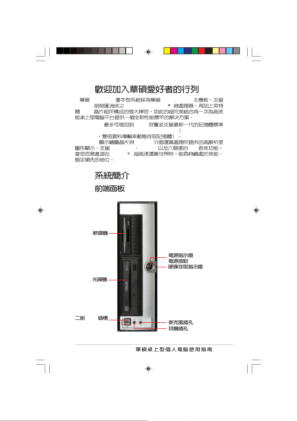
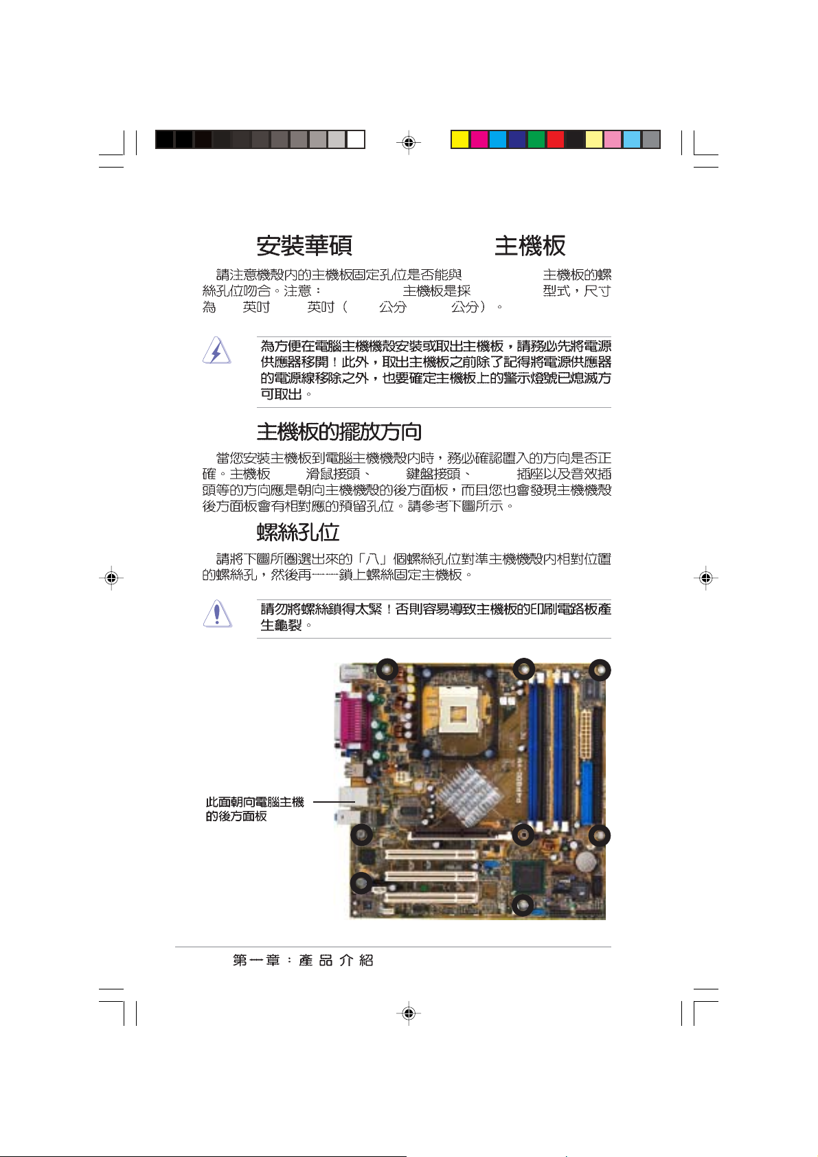
1.1
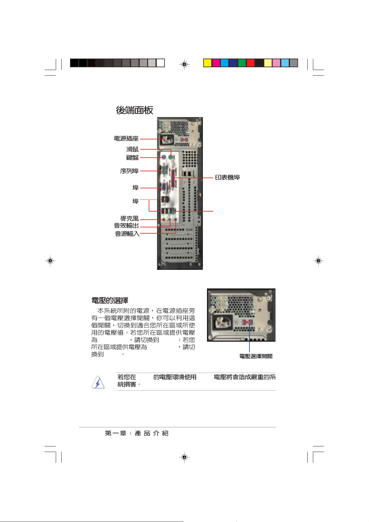
1.2
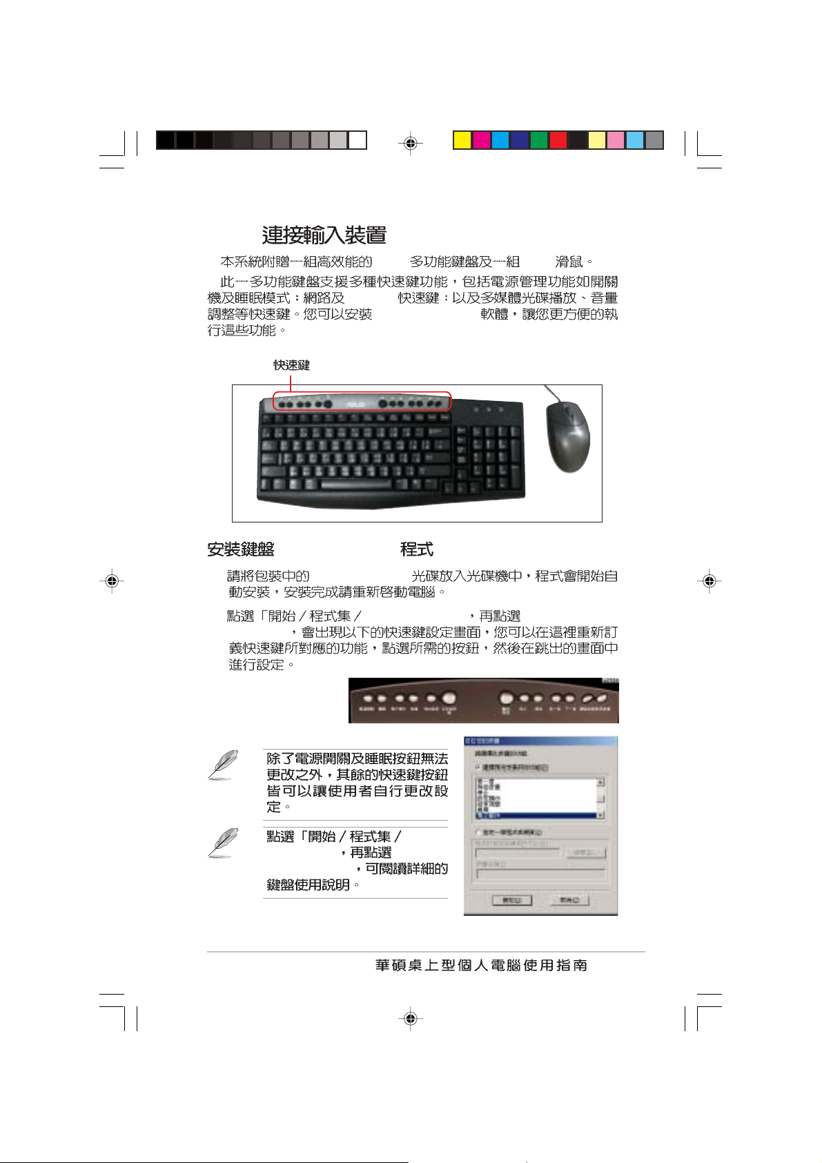
1.3
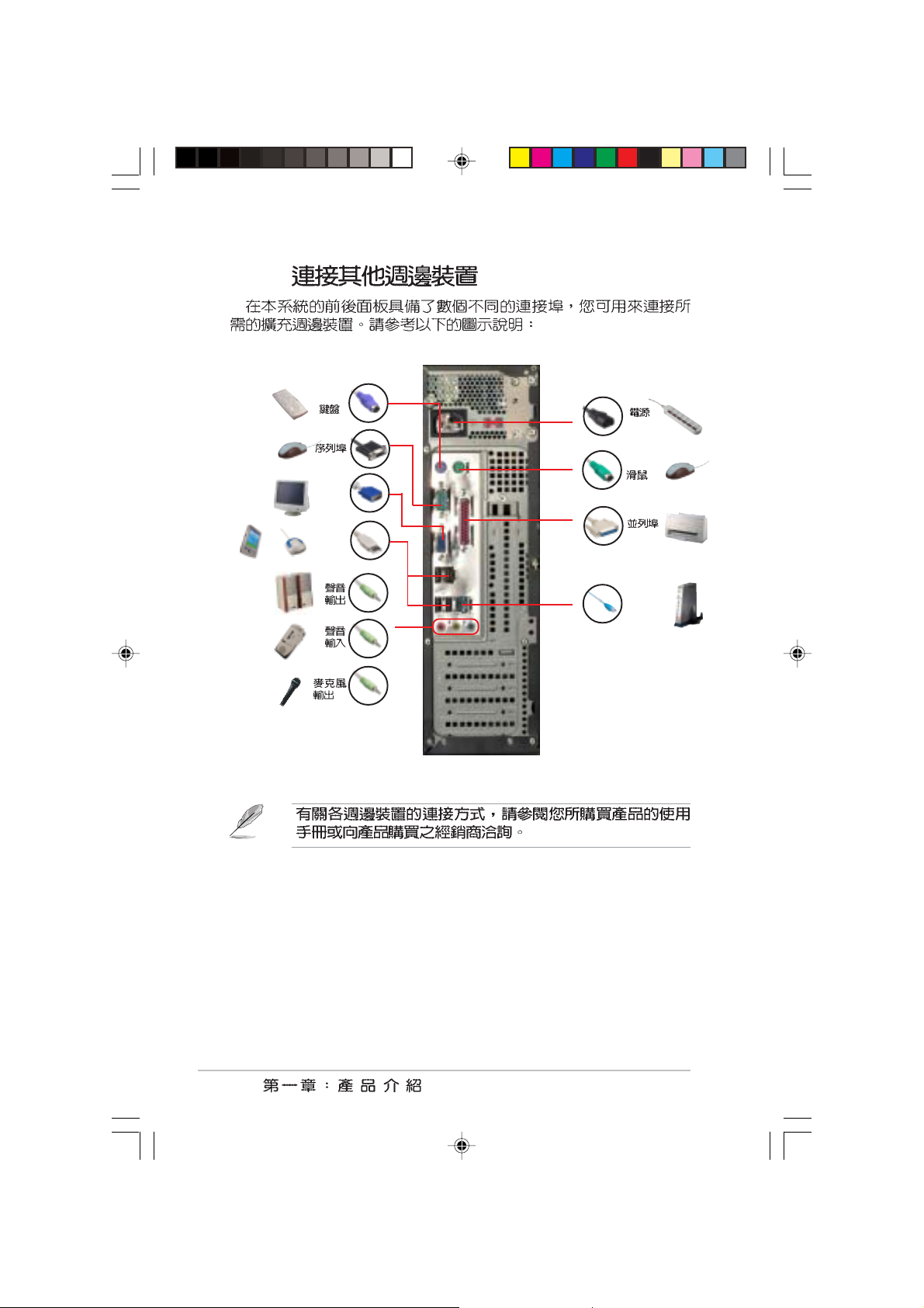
1.4
1.5 P4P800-VM
1.6
1.7 P4P800-VM
.................................................................................................
.................................................................................................
.............................................................................................
1.4.1 P4P800-VM
1.4.2
1.7.1
1.7.2
..................................................................................
.......................................................................................
..................................................................................
1-1
..................................................................
...........................................
..........................................................
..............................................................
..................................................................
1-3
1-3
1-6
1-9
1-9
1-11
1-14
1-15
1-16
1-16
1-16
6
7
8
9
10
1.8 CPU
1.8.1
1.8.2 Socket-478 Pentium® 4
1.9
1.9.1
1.9.2
1.9.3
..........................................................................................
...........................................................................................
............................................................................
..............................................................................
1-17
1-17
.......................................
......................................................................
......................................................................
1-18
1-19
1-19
1-22
1-22
3
1.11
1.12
.........................................................................................
.....................................................................
BIOS
2.1 BIOS
2.1.1
2.1.2 AFUDOS BIOS
2.1.3 EZ Flash BIOS
2.1.4 CrashFree BIOS2
2.2 BIOS
2.2.1 BIOS
2.3 Main Menu
2.3.1 IDE Primary/Secondary/Third/Fourth IDE
Master/Slave
2.3.2 IDE IDE Configuration
2.3.3 System Infomation
2.4 Advanced Menu
2.4.1 CPU Configuration
2.4.2 Chipset
2.4.3 OnBoard Devices Configuration
2.4.4 PCI PCI PnP
2.4.5 USB USB Configuration
.......................................................................................
...................................................................
........................................................................
........................................
..........................................
...............................................................
..................................................................
.........................................................................
.....................................................................
......................................
.............................................
.............................................................
........................................
..............................................................
......................................
...................................
................
1-23
1-24
2-3
2-3
2-3
2-5
2-6
2-8
2-9
2-11
2-12
2-13
2-15
2-15
2-16
2-16
2-19
2-20
2-22
2.5 Power Menu
2.5.1 APM Configuration
2.5.2 Hardware Monitor
4
...................................................................
...........................
.....................................
2-24
2-25
2-27
2.6 Boot Menu
2.6.1 Boot Device Priority
2.6.2 Boot Settings Configuration
2.6.3 Security
2.7 BIOS Exit Menu
3.1
3.2
3.2.1
3.2.2 Driver Menu
3.2.3 Utilities Menu
3.2.4
3.3
3.3.1
3.3.2 My Logo2
3.3.3 SoundMAX
.........................................................................................
.................................................................................................
......................................................................
.........................................................
............................................................
..............................................................
.................................................
........................................................................
............................................................................
TM
.......................................................................
......................................................
2-28
..................................
.......................
................................................
..............................................
2-28
2-29
2-31
2-33
3-3
3-3
3-3
3-4
3-5
3-6
3-6
3-6
3-8
3-10
3.4 Recovery CD
..........................................................
3-12
5
•
•
•
BIOS
BIOS
BIOS
6
Pin
e
Jumper Mode
[1-2]
JumperFree™ Mode
[2-3]
12
Jumper Mode
23
Jumper Fre
(Default)
1.
http://taiwan.asus.com.tw
2.
•
•
•
USB
PS/2
•
•
PC
•
•
Norton AntiVirus 2004
•
•
ROM/DVD-RW
•
CD-ROM/CD-RW/DVD-
7
ASUSTeK COMPUTER INC.
150
886-2-2894-3447
0800-093-456
AM 9:00 PM 9:00
AM 9:00 PM 6:00
886-2-2890-7698
http://taiwan.asus.com.tw/
ASUS COMPUTER INTERNATIONAL
44370 Nobel Drive, Fremont, CA 94538, USA
+1-502-995-0883
+1-502-933-8713
tmdl@asus.com
+1-502-995-0883
+1-502-933-8713
tsd@asus.com
http://www.asus.com
ASUS COMPUTER GmbH /
Harkortstr. 25, 40880 Ratingen, BRD, Germany
49-2102-9599-31
sales@asuscom.de
49-2102-9599-0 ... /
49-2102-9599-10 ..
49-2102-9599-11
http://www.asuscom.de/support
http://www.asuscom.de
8
•
•
•
•
•
•
•
•
•
•
•
•
/
9
•
•
•
•
•
•
•
•
10
•
•
•
•
•
IC
1.1
..................................................................
1-3
1.2
1.3
1.4
1.5 P4P800-VM
1.6
1.7 P4P800-VM
1.8 CPU
1.9
1.10
1.11
.................................................................................................
.................................................................................................
.............................................................................................
.......................................................................................
............................................................................
...........................................................................................
.........................................................................................
1-3
1-4
1-9
..........................................................
..............................................................
.....................................................................
1-14
1-15
1-16
1-17
1-19
1-23
1-24
1.1
AS-D260 P4P800-VM
800MHz Socket-478 Pentium4
865G
AS-D260 4GB
PC3200/2700/2100 non-ECC DDR SDRAM Double Data Rate
SDRAM
Graphics 2
AGP 8X
Serial ATA USB 2.0 PCI
Pentium 4
Intel Extreme
1.2
1.2.1
USB
1-3
1.2.2
PS/2
PS/2
VGA
USB
RJ-45 LAN
100-127V 115V
230V
230V 115V
1-4
200-240V
115V/ 230V
1.2.3
PS/2 USB
E-Mail
Touch Manager
Touch Manager
1. Touch Manager
2. Touch Manager Customize the
hotkeys
Manager
Manager Help
Touch
Touch
1-5
1.2.4
PS/2
PS/2
VGA
USB
RJ-45
1-6

1.3
478 ZIF
Socket-478 Pentium® 4 512KB L2 0.
13
Hyper-Threading technology
Intel Prescott
Dual DDR400
DDR SDRAM Double Data Rate SDRAM
SDRAM
4GB 400MHz DDR SDRAM 3D
ATA
ATA
ATA 2 ATA
ATA ATA
150MB
800/533/400MHz
3.2+ GHz
non-ECC PC3200/2700/2100
Extreme Graphics 2
865G Extreme Graphics 2
3D/2D
CrashFree BIOS2
CrashFree BIOS2
BIOS BIOS
BIOS
BIOS ROM
1-7
MyLogoTM
MyLogoTM
EZ Flash BIOS
EZ Flash BIOS
BIOS DOS
USB 2.0
USB 2.0 USB 1.1
12 Mbps USB 2.0 480 Mbps USB
2.0
2.0
P4P800-VM ADI AD1980 AC 97
90dB dynamic range
Sony Philips S/PDIF Sony-
Philips Digital Interface
USB 1.1 1-29
5.1
3-7
USB
1-8
Win NT Win98SE
WinME Win2000
WinXP
1.4
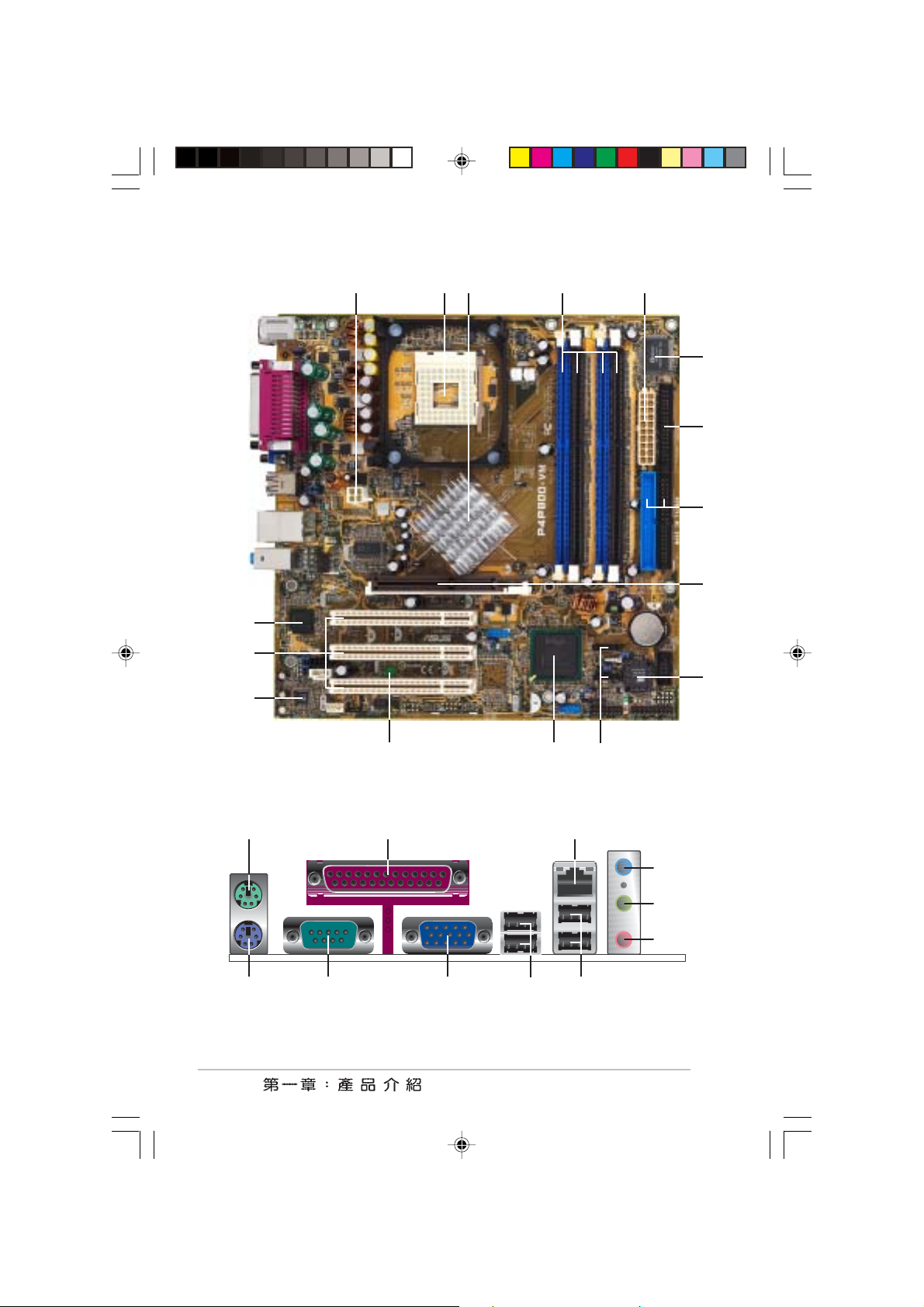
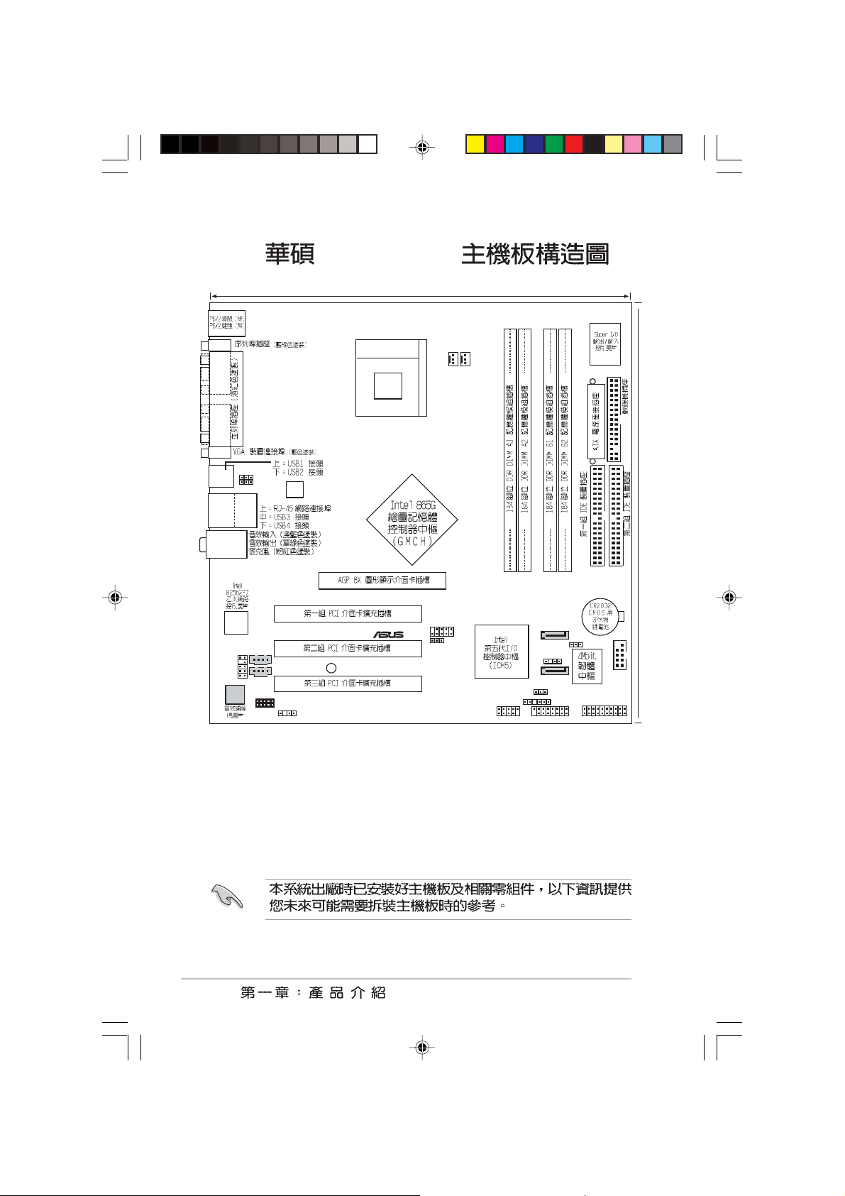
P4P800-VM
P4P800-VM
P4P800-VM
1.4.1 P4P800-VM
1. ATX 12
2.
3.
4. DDR
5. ATX
6. Super I/O
7.
8. IDE
9. AGP 8X
10.
11. ATA
12.
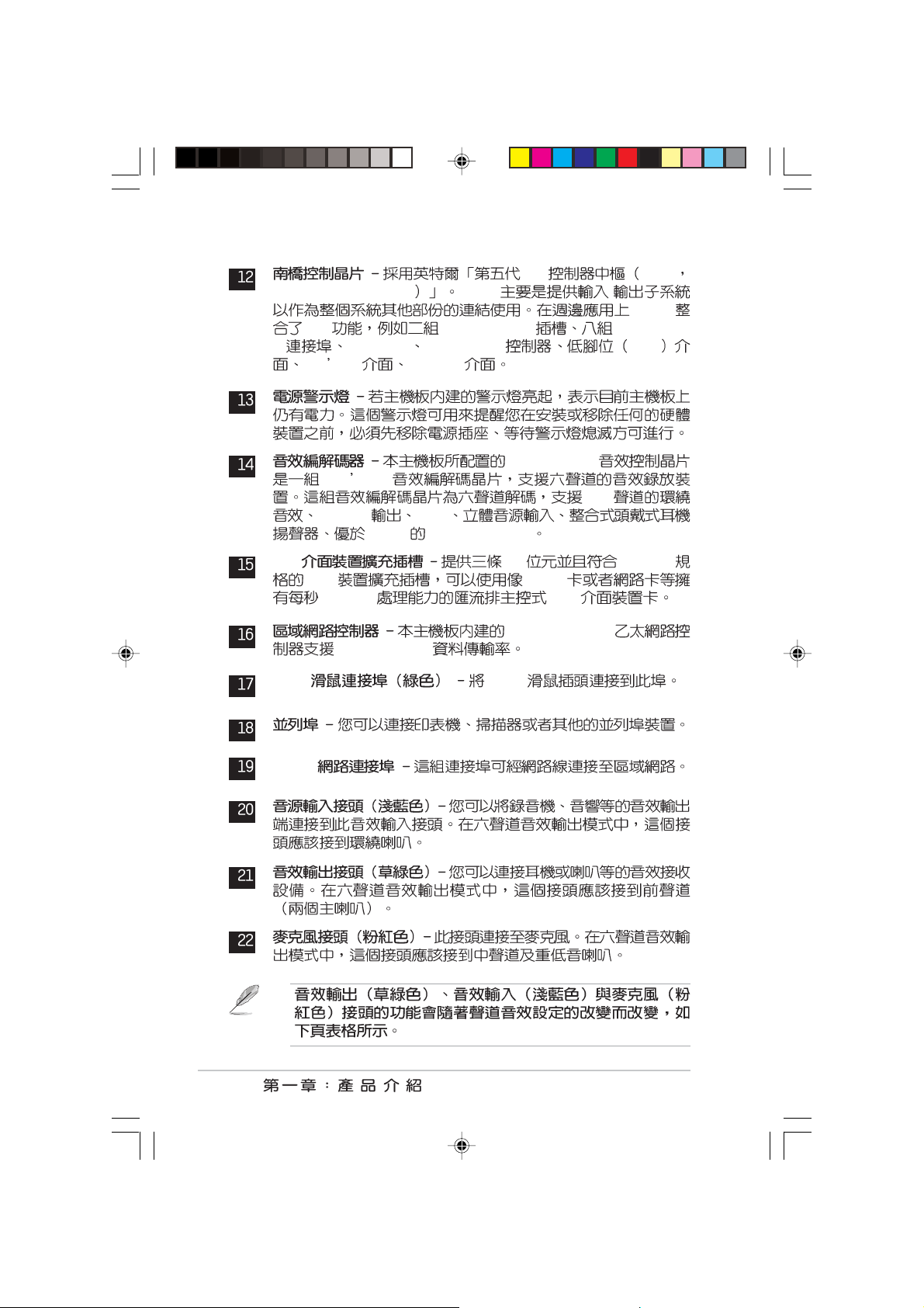
13.
14.
15.PCI
16.LAN
17.PS/2
18.
19.RJ-45
20.
21.
22.
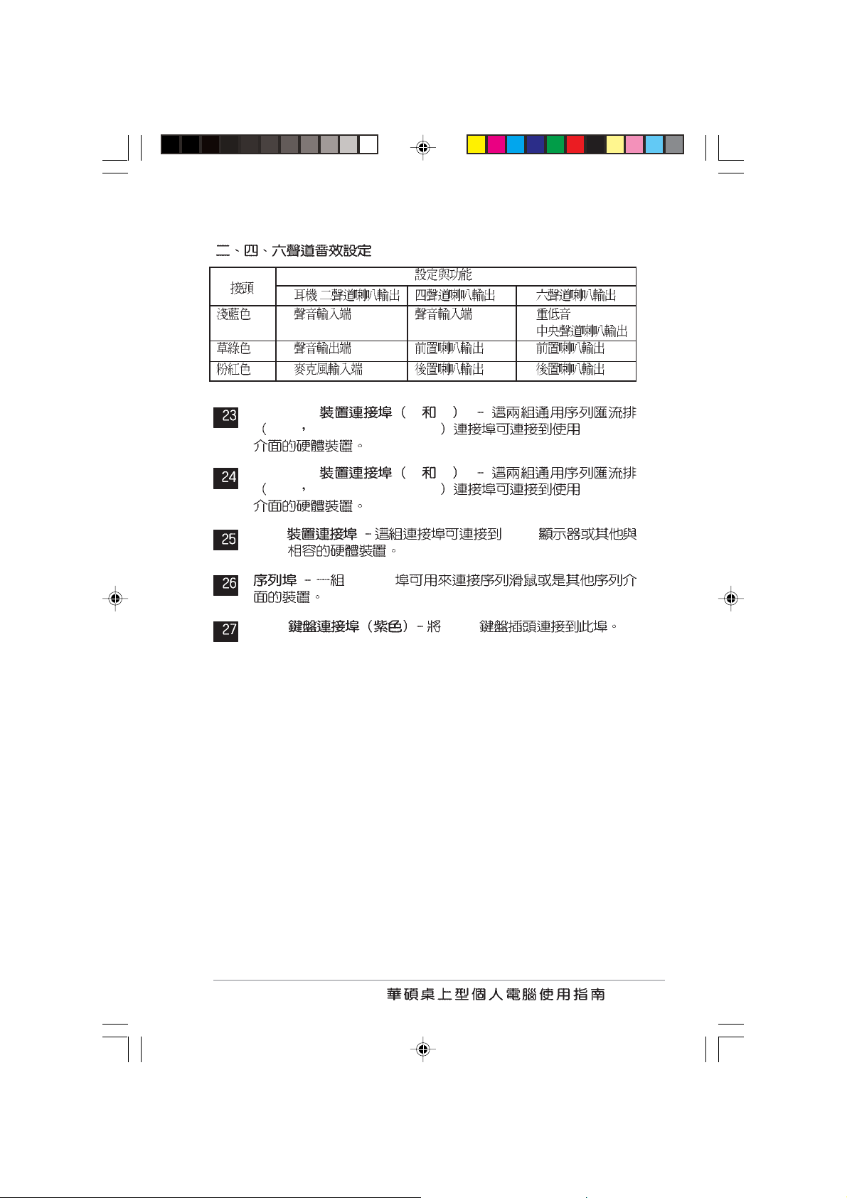
23.
USB 2.0 3 4
24.
USB 2.0 1 2
25.VGA
26.
27.PS/2
1-9
43
16
2
5
1
0
17
18 19
15
14
6
7
8
9
1
27
1-10
13
12
11
20
21
22
2526
24
23
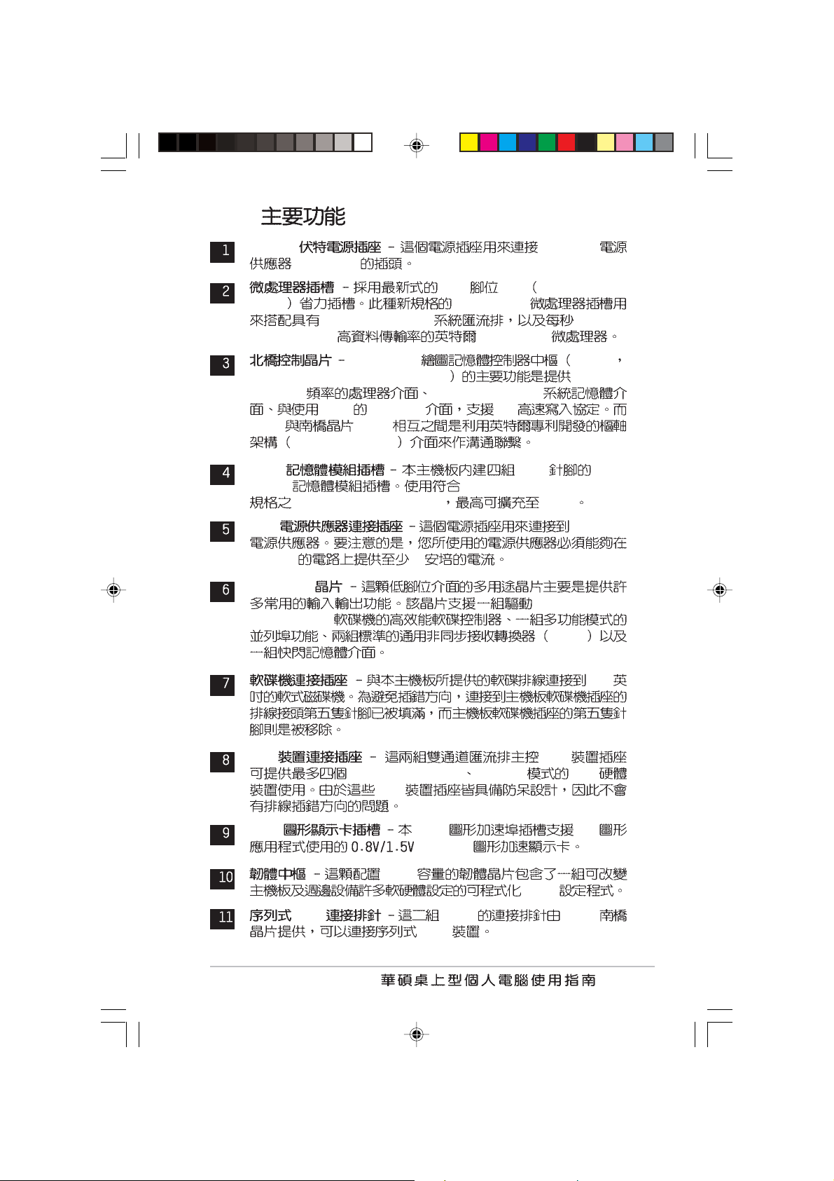
1.4.2
ATX 12 ATX 12V
4 Pin 12V
478 ZIF Zero Insertion
Force
800/533/400MHz 6.4GB/
4.3GB/3.2GB
Intel® 865G GMCH
Graphics Memory Controller Hub 800/533/
400MHz
1.5V AGP 3.0 8X
MCH ICH5
Hub Architecture
DDR 184 DDR
DIMM
non-ECC DDR SDRAM 4 GB
ATX ATX 12V
+5VSB 1
Super I/O
44M/2.88MB
Socket-478
Pentium® 4
400/333/266MHz
PC3200/PC2700/PC2100
360K/720K/1.
UART
3.5
IDE IDE
Ultra DMA 100/66 PIO 3/4 IDE
IDE
AGP AGP 3D
AGP 8X
4Mb
BIOS
ATA 7-pin ICH5
ATA
1-11
I/O ICH5
I/O Controller Hub 5 ICH5 /
ICH5
I/O ATA 100 IDE USB 2.0/1.
1
PCI 32 PCI 2.2
PS/2 PS/2
I/O APIC SMBus 2.0 LPC
AC 97 PCI 2.2
ADI AD1980
AC 97
5.1
S/PDIF AUX
90dB dynamic range
PCI SCSI
133MB PCI
Intel® 82562EZ
10/100 Mbps
1-12
RJ-45
/
/
USB 2.0 3 4
USB Unervisal Serial Bus USB 2.0
USB 2.0 1 2
USB Unervisal Serial Bus USB 2.0
VGA VGA
VGA
COM1
PS/2 PS/2
1-13
1.5 P4P800-VM
24.5cm (9.6in)
®
Socket 478
CHA_FAN1
CPU_FAN
USBPW12
USBPW34
FP_AUDIO1
MDC1
CD1
AUX1
ATX12V1
SPDIF1
SB_PWR1
USB56
USBPW56
P4P800-VM
USBPW78
USB78
SATA2
CHASSIS1
SATA1
SMB1
GAME1
PRI_IDE1
CLRTC1
FLOPPY1
24.5cm (9.6in)
SEC_IDE1
COM2
PANEL1
1-14
1.6
d
1.
2.
3.
4.
5. ATX
OFF
/
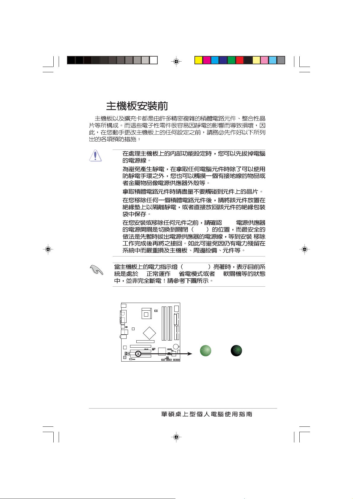
SB_PWR
(1) (2) (3)
P4P800-VM
®
P4P800-VM Onboard LED
ON
Standby
Power
SB_PWR1
OFF
Powere
Off
1-15
1.7 P4P800-VM
P4P800-VM
P4P800-VM micro-ATX
9.6 x 9.6 24.5 x 24.5
1.7.1
PS/2 PS/2 COM1
1.7.2
1-16
1.8 CPU
1.8.1
P4P800-VM 478
ZIF Socket-478 Pentium® 4 512KB
L2
400MHz
Threading Technology
Intel Hyper-Threading
0.13 800/533/
execution trace cache
6.4GB Hyper Intel® Pentium® 4
Prescott
Pentium® 4
Pentium® 4 Socket-478
1. Intel Pentium 4 HyperThreading
2. Windows XP Hyper-Threading
BIOS
Hyper-Threading
3. Windows XP Service pack 1
4. Hyper-Threading
BIOS Hyper-Threading
5. Hyper-Threading
www.intel.com/info/hyperthreading
Hyper-Threading
1. Hyper-Threading Intel Pentium 4
2. BIOS Advanced Menu
CPU Configuration Hyper-Threading
Technology
Hyper-Threading 2-14
3.
Enabled
1-17

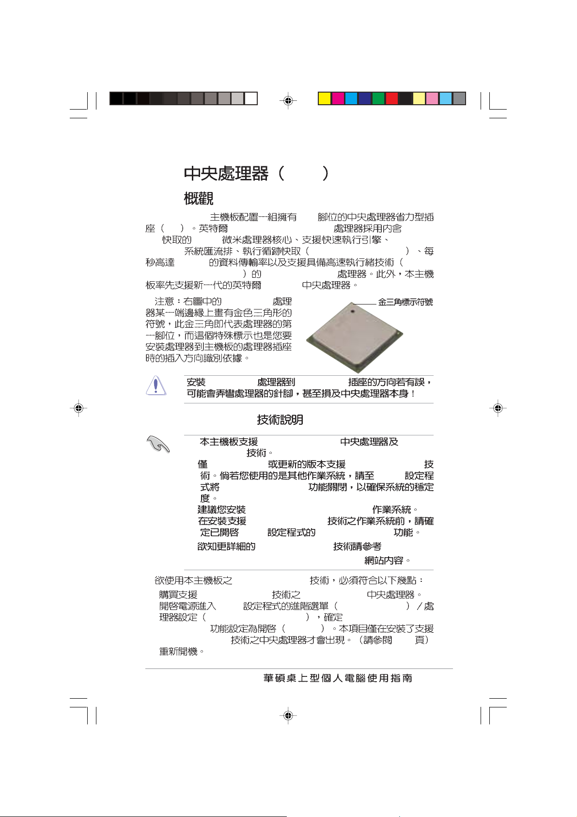
1.8.2 Socket-478 Pentium
0
Pentium® 4
1. Socket 478
2. Socket-478
90
3. Pentium® 4
4. Pentium® 4
®
4
90 -10
Pentium® 4
Socket-478
5.
1-18

1.9
P4P800-VM DDR DIMM Double Data Rate
non-ECC PC3200/
®
DDR DIMM
DIMM_A1
DIMM_A2
DIMM_B1
P4P800-VM
CPU Front Side Bus FSB
64, 128, 256, 512MB 1GB DDR DIMM
PC2700/PC2100
4GB
P4P800-VM 184-Pin DDR DIMM Sockets
DDR
1.9.1
DIMM_B2
80 Pins104 Pins
1. DDR 1
2.
3. CAS Latency
4.
2
5.
6. ICH5
1GB ( 4GB)
3GB 4GB
1-19

1.
DDR DIMM_A1( ) DIMM_A2( ) DIMM_B1( ) DIMM_B2( )
---
- --
-- -
---
- -
- -
DIMM_A1 DIMM_B1 DIMM_A2
DIMM_B2
1
2. CPU
CPU FSB DDR DDR
800MHz PC3200/PC2700*/PC2100 400/333*/266MHz
533MHz PC2700/PC2100 333/266MHz
400MHz PC2100 266MHz
1-20
800MHz
PC2700 DDR
320MHz 333MHz

3 DDR 400 QVL
256MB Samsung M368L3223DTM-CC4 Samsung K4H560838D-TCC4 4
256MB Samsung M368L3223ETM-CCC Samsung K4H560838E-TCCC 4
512MB Samsung M368L6432ETM-CCC Samsung K4H560838E-TCCC 4
256MB Infineon HYS64D32300GU-5-B Infineon HYB25D256800BT-5B 4
512MB Infineon HYS64D64320GU-5-B Infineon HYB25D256800BT-5B 2
256MB TranscendTS32MLD64V4F3 Samsung K4H560838D-TCC4 2
512MB TranscendTS64MLD64V4F3 Samsung K4H560838D-TCC4 2
256MB Winbond W9425GCDB-5 Winbond W942508CH-5 4
512MB Winbond W9451GCDB-5 Winbond W942508CH-5 4
256MB A DATA MDOAD5F3G315B1ECZ Samsung K4H560838D-TCC4 2
256MB TwinMOS MDSTTUF08108L294K4FW0/T TwinMOS TMD7608F8E50B 2
512MB Hynix HYMD264646B8J-D43 AA Hynix HY5DU56822BT-D43 4
512MB Apacer 77.10636.465 Samsung K4H560838D-TCC4 4
http://www.asus.com
1-21

1.9.2
1.
2.
3.
DDR DIMM
1-22
1.9.3
1.
2.

1.10
1. USB 3-pin USBPW12, USBPW34, USBPW56,
USBPW78
+5V USB S1
+5VSB S3
S4
USB
+5V [1-2]
USBPW_12 USBPW_34
USB USBPW_56 USBPW_78
USB
USBPW12
USBPW34
2321
+5V
P4P800-VM
®
P4P800-VM USB Device Wake Up
USBPW56
USBPW78
+5V
(Default)
1. USB +5VSB
2.
+5VSB
(Default)
2321
+5VSB
500mA/+5VSB
+5VSB
1-23

S
2. CMOS CLRTC1
®
CMOS
CMOS
1
2 CLRTC [1-2] [2-3]
CMOS [1-2]
3
4 <Del> BIOS
BIOS
P4P800-VM
®
P4P800-VM Clear RTC RAM
CMOS
1.11
1. SMBus 6-1 pin SMB1
SMBus System Management Bus
SMBus
P4P800-VM
CLRTC1
12 23
Normal Clear CMO
(Default)
SMB1
1
+3V
Ground
P4P800-VM SMBus Connector
SMBCLK
FLOATING
SMBDATA
1-24

2. 34-1 pin FLOPPY1
n
FLOPPY1
1
t)
P4P800-VM
NOTE: Orient the red markings o
the floppy ribbon cable to PIN 1.
Pin 1
®
PIN 1
P4P800-VM Floppy Disk Drive Connector
IDE
3. 4-1 pin CHASSIS1
CHASIS Chassis
Signal
Ground
Chassis Signal Ground
CHASSIS
P4P800-VM
®
P4P800-VM Chassis Alarm Lead
+5VSB_MB
Chassis Signal
GND
(Defaul
1-25

ATA ATA
4. IDE 40-1 pin PRI_IDE1, SEC_IDE1
IDE
IDE IDE ( CDROM
ZIP MO ) IDE
Master
Slave
IDE
IDE
Slave
1. IDE
UltraDMA
2. UltraDMA 100/66
1-26
P4P800-VM
®
P4P800-VM IDE Connectors
UltraDMA 100/66 IDE
PRI_IDE1
PIN 1
80 IDE
Pin 1
SEC_IDE1

5. ATA 7-pin SATA1, SATA2
ATA
ATA
ATA 150MB
133MB ATA Ultra ATA/133
SATA2
GND
GND
GND
RSATA_TXP2
RSATA_TXN2
RSATA_RXP2
P4P800-VM
RSATA_RXN2
SATA1
®
GND
GND
P4P800-VM SATA Connectors
RSATA_TXP1
RSATA_TXN1
RSATA_RXP1
GND
RSATA_RXN1
ATA ATA
Intel ICH5 ATA ATA
Windows 2000/XP
IDE
Windows 2000/XP ICH5
6 IDE
MS-DOS Windows 98SE/Me/NT4.0 ICH5
4 IDE
0 1
-ATA -ATA
(2 ) (2 ) (1 ) (1 )
1. Windows 2000/XP
2. Windows 98/Me/NT4.0
A B C--
:
-
1-27

IDE BIOS
BIOS ATA ATA
BIOS
2.3.6 IDE
BIOS A B C
Windows 2000/XP Windows 98/Me/NT4.0
Onboard IDE Operate Mode Enhanced Mode Compatible Mode Compatible Mode Compatible Mode
Enhanced Mode Support On S-ATA - - IDE Port Settings - P-ATA & S-ATA P-ATA & S-ATA P-ATA Only
Windows 2000/XP BIOS Enhanced
Mode S-ATA 2 ATA 4
ATA
6. 20-pin ATXPWR1, 4-pin ATX12V1
ATX 12V
20 ATXPWR1
+12V
ATX 12V +12V
8 +5VSB
1
230
300
1-28
4-pin ATX12V
P4P800-VM
®
P4P800-VM ATX Power Connector
GND
+12V DC
ATX12V1
GND
+12V DC
ATXPWR1
+3.3VDC
-12.0VDC
COM
PS_ON#
COM
COM
COM
-5.0VDC
+5.0VDC
+5.0VDC
+3.3VDC
+3.3VDC
COM
+5.0VDC
COM
+5.0VDC
COM
PWR_OK
+5VSB
+12.0VDC

®
7. COM2 10-1 pin COM2)
COM2 COM2
BIOS
COM2 COM2
COM2 COM2
COM2
P4P800-VM
PIN 1
P4P800-VM Serial COM2 Bracket
8. 10-1 FP_AUDIO1
Intel
Line out_R/BLINE_OUT_R
Line out_L/BLINE_OUT_L
P4P800-VM
®
P4P800-VM Front Panel Audio Connector
FP_AUDIO1
BLINE_OUT_L
BLINE_OUT_R
AGND
+5VA
/
Line out_L
NC
Line out_R
MICPWR
MIC2
1-29

9. /
1
)
3-pin CPU_FAN1, CHA_FAN1
350 720 8.88 1
2.22 26.64 /+12
+12V GND
CHA_FAN1
GND
+12V
P4P800-VM
®
Rotation
P4P800-VM 12-Volt Fan Connectors
10. 4-pin CD1, AUX1
AUX1(White
P4P800-VM
®
P4P800-VM Internal Audio Connectors
CPU_FAN
GND
+12V
Rotation
CD1(Black)
Ground
Ground
Left Audio Channel
MPEG
Right Audio Channel
1-30

®
11. 4-1 pin SPDIF_OUT1
®
S/PDIF
S/PDIF
SPDIF1
P4P800-VM
GND
+5V
SPDIFOUT
P4P800-VM Digital Audio Connector
12. /MIDI 16-1 pin GAME1
/MIDI USB 2.0/
/MIDI /MIDI
S/PDIF
MIDI
P4P800-VM
GND
GND
+5V
J1B1
J1CX
J1CY
J1B2
+5V
GAME1
P4P800-VM Game Connector
J2B2
J2CY
MIDI_IN
+5V
J2B1
J2CX
MIDI_OUT
1-31

13.USB 10-1 pin USB56, USB78
USB
USB USB
USB 2.0 480 Mbps
USB 1.1 12 Mbps 40
USB 2.0/ USB
USB 2.0
USB
USB 2.0
P4P800-VM
1-32
®
P4P800-VM USB 2.0 Header
USB56
GND
NC
GND
USB_P5+
USB_P5-
USB+5V
1
USB+5V
USB_P6-
USB_P6+
USB78
1
USB+5V
USB_P8-
USB_P8+
USB+5V
USB_P7-
USB_P7+
GND
GND
NC

14. MDC (4-1 pin MDC1)
P4P800-VM
®
MDC1
P4P800-VM MDC Header
15. 20-pin PANEL)
P4P800-VM
®
P4P800-VM System Panel Connectors
* Requires an ATX power supply.
AC97_SYNC
MODEM_IN
AC97_SDIN1
GND
GND
+3VSB
AC97_RST#
Power LED
PLED
+5 V
HD_LED-
HD_LED+
IDELED
SMI Lead
AC97_BITCLK
AC97_SDOUT
Speaker
Connector
+5V
Ground
Ground
ExtSMI#
PWRBIN
ATX Power
Switch*
Ground
Speaker
Ground
Reset
Ground
Reset SW
•
3-1 pin PLED
1-33

IDE 2-pin IDE_LED
•
IDE_LED IDE
IDE
•
•
Green
ATX
•
BIOS
•
/ 2-pin PWR
4-pin SPKR
2-pin SMI
2-pin RESET
Reset
1-34

BIOS
BIOS
BIOS
BIOS

2.1 BIOS
...................................................................
2-3
2.2 BIOS
2.3 Main Menu
2.4 Advanced Menu
2.5 Power Menu
2.6 Boot Menu
2.7 BIOS Exit Menu
.......................................................................................
.........................................................................
...................................................................
......................................................................
2-8
2-11
.............................................................
............................................................
2-15
2-24
2-28
2-33

2.1 BIOS
BIOS
BIOS
2.1.1
1.
DOS
1.44 MB DOS
format A:/S <Enter>
Windows Win98/ME
a.
b.
c.
d.
1.44 MB
2. BIOS
2.1.2 AFUDOS BIOS
DOS AFUDOS.EXE
1. http://www.asus.com BIOS
BIOS
BIOS
2. AFUDOS.EXE
3.
2-3

4. DOS
afudos /
i< . > afudos /iP4P800VM.rom
. BIOS
A:\>afudos /iP4P800VM.rom
AMI Firmware Update Utility - Version 1.10
Copyright (C) 2002 American Megatrends, Inc. All rights
reserved.
Reading file ..... done
Erasing flash .... done
Writing flash .... 0x0008CC00 (9%)
BIOS
BIOS
BIOS DOS
A:\>afudos /iP4P800VM.rom
AMI Firmware Update Utility - Version 1.10
Copyright (C) 2002 American Megatrends, Inc. All rights
reserved.
Reading file ..... done
Erasing flash .... done
Writing flash .... done
Verifying flash .. done
A:\>
5. BIOS
BIOS
2-4
BIOS

2.1.3 EZ Flash BIOS
EZ Flash BIOS
DOS EZ Flash
BIOS Power-
On Self Test
1. BIOS
2.
3. POST <Alt> + <F2>
User recovery requested. Starting BIOS recovery...
Checking for floppy...
POST <Alt> + <F2> EZ Flash
EZ Flash BIOS
P4P800VM.rom EZ
Flash
EZ Flash
BIOS
Floppy not found
P4P800VM.ROM not found!
4.
EZ Flash
BIOS
User recovery requested. Starting BIOS recovery...
Checking for floppy...
Floppy found!
Reading file “P4P800VM.rom”. Completed.
Start flashing...
Flashed successfully. Rebooting.
2-5

2.1.4 CrashFree BIOS2
BIOS
CrashFree BIOS2 BIOS
BIOS BIOS
1. BIOS
P4P800VM.rom
2. BIOS
BIOS 2.1.1
BIOS
1.
2. BIOS
Bad BIOS checksum. Starting BIOS recovery...
Checking for floppy...
3.
Bad BIOS checksum. Starting BIOS recovery...
Checking for floppy...
Floppy found!
Reading file “P4P800VM.rom”. Completed.
Start flashing...
BIOS
4.
2-6
BIOS

BIOS
1.
2. BIOS
Bad BIOS checksum. Starting BIOS recovery...
Checking for floppy...
3.
Bad BIOS checksum. Starting BIOS recovery...
Checking for floppy...
Floppy not found!
Checking for CD-ROM...
CD-ROM found.
Reading file “P4P800VM.rom”. Completed.
Start flashing...
BIOS
4.
BIOS
BIOS http://www.asus.com
BIOS
2-7

2.2 BIOS
BIOS Basic Input and Output System
BIOS
BIOS
BIOS
RUN SETUP BIOS
BIOS
Flash ROM BIOS
Flash ROM
BIOS BIOS
RAM
BIOS
POST Power-On Self Test
DELETE
DELETE
BIOS
CMOS
RESET Ctrl + Alt + Delete
BIOS
BIOS
Setup Defaults
BIOS
BIOS BIOS
BIOS
2-8
BIOS
2.7 BIOS Load
http://www.asus.com

2.2.1 BIOS
System Time [18:29:27]
System Date [Wed 03/19/2003]
Legacy Diskette A [1.44M, 3.5 in]
Primary IDE Master :[ST320413A]
Primary IDE Slave :[ASUS CD-S520]
Secondary IDE Master :[Not Detected]
Secondary IDE Slave :[Not Detected]
Third IDE Master :[Not Detected]
Fourth IDE Master :[Not Detected]
IDE Configuration
System Information
BIOS
BIOS
Use [ENTER], [TAB]
or [SHIFT-TAB] to
select a field.
Use [+] or [-] to
configure system time.
Select Screen
Select Item
+- Change Field
Tab Select Field
F1 General Help
F10 Save and Exit
ESC Exit
2-9

[ Enter ]
Enter ]
System Time [18:29:27]
System Date [Wed 03/19/2003]
Legacy Diskette A [1.44M, 3.5 in]
Primary IDE Master :[ST320413A]
Primary IDE Slave :[ASUS CD-S520]
Secondary IDE Master :[Not Detected]
Secondary IDE Slave :[Not Detected]
Third IDE Master :[Not Detected]
Fourth IDE Master :[Not Detected]
IDE Configuration
System Information
[
Advanced Chipset settings
WARNING: Setting wrong values in the sections below
may cause system to malfunction.
Configure DRAM TIming by SPD [Disabled]
DRAM CAS# Latency [2.5 Clocks]
DRAM RAS# Precharge [4 Clocks]
DRAM RAS# to CAS# Delay [4 Clocks]
DRAM Precharge Delay [8 Clocks]
DRAM Burst Length [8 Clocks]
Graphic Adapter Priority [AGP/PCI]
Graphics Aperture Size [ 64 MB]
Spread Spectrum [Enabled]
ICH Delayed Transaction [Enabled]
MPS Revision [1.4]
Use [ENTER], [TAB]
or [SHIFT-TAB] to
select a field.
Use [+] or [-] to
configure system time.
Select Screen
Select Item
+- Change Field
Tab Select Field
F1 General Help
F10 Save and Exit
ESC Exit
Select Screen
Select Item
+- Change Option
F1 General Help
F10 Save and Exit
ESC Exit
PageUp/ PageDown
2-10
/
BIOS

2.3 Main Menu
BIOS
2.2.1
System Time [18:29:27]
System Date [Wed 03/19/2003]
Legacy Diskette A [1.44M, 3.5 in]
Primary IDE Master :[ST320413A]
Primary IDE Slave :[ASUS CD-S520]
Secondary IDE Master :[Not Detected]
Secondary IDE Slave :[Not Detected]
Third IDE Master :[Not Detected]
Fourth IDE Master :[Not Detected]
IDE Configuration
System Information
Use [ENTER], [TAB]
or [SHIFT-TAB] to
select a field.
Use [+] or [-] to
configure system time.
Select Screen
Select Item
+- Change Field
Tab Select Field
F1 General Help
F10 Save and Exit
ESC Exit
System Time [XX:XX:XX]
00 23 00 59 00 59
Tab Tab + Shift
System Date [DAY XX/XX/XXXX]
1 12 1 31 00 99 Tab
Tab + Shift
Legacy Diskette A [1.44M, 3.5 in.]
[None][360K 5.
25 in.] [1.2M 5.25 in.] [720K 3.5 in.] [1.44M 3.5 in,] [2.88M 3.5
in.]
2-11

2.3.1 IDE Primary/Secondary/
Third/Fourth IDE Master/Slave
BIOS IDE
ATA IDE ATA
[Enter]
Primary IDE Master
Device : Hard Disk
Vendor : ST320413A
Size : 20.0GB
LBA Mode : Supported
Block Mode : 16 Sectors
PIO Mode : Supported
Async DMA : MultiWord DMA-2
Ultra DMA : Ultra DMA-5
SMART Monitoring: Supported
Type
LBA/Large Mode
Block (Multi-sector Transfer)
PIO Mode
DMA Mode
Smart Monitoring
32Bit Data Transfer
[Auto]
[Auto]
[Auto]
[Auto]
[Auto]
[Auto]
[Disabled]
N/A
Type [Auto]
IDE Auto
IDE CDROM IDE
ARMD (ATAPI )
IDE ZIP LS-120 MO
[Not Installed] [Auto] [CDROM] [ARMD]
LBA/Large Mode [Auto]
LBA [Auto]
LBA LBA
[Disabled] [Auto]
Select the type
of device connected
to the system.
Select Screen
Select Item
+- Change Option
F1 General Help
F10 Save and Exit
ESC Exit
BIOS
Block (Multi-sector Transfer) [Auto]
2-12
BIOS
[Auto]
[Disabled]
[Disabled][Auto]

PIO Mode [Auto]
PIO [Auto] [0] [1] [2] [3] [4]
DMA Mode [Auto]
DMA [Auto] [SWDMA0] [SWDMA1]
[SWDMA2] [MWDMA0] [MWDMA1] [MWDMA2] [UDMA0] [UDMA1]
[UDMA2] [UDMA3] [UDMA4] [UDMA5]
SMART Monitoring [Auto]
Smart Monitoring, Analysis, and
Reporting Technology [Auto] [Disabled] [Enabled]
32Bit Data Transfer [Disabled]
32 [Disabled] [Enabled]
2.3.2 IDE IDE Configuration
IDE
IDE Configuration
Onboard IDE Operate Mode [Enhanced Mode]
Enhanced Mode Support On [S-ATA Only]
IDE Detect Time Out (Sec) [35]
Select Screen
Select Item
+- Change Option
F1 General Help
F10 Save and Exit
ESC Exit
Onboard PCI IDE Operate Mode [Enhanced Mode]
MS-DOS, Windows 98SE/ME/NT4.0 [Compatible
Mode] Windows 2000/XP
[Enhanced Mode] [Compatible Mode] [Enhanced
Mode]
1-26 ATA
...
2-13

Enhanced Mode Support On [S-ATA]
[S-ATA]
ATA ATA
MS-DOS Windows 98SE/ME/NT4.0
ATA [P-ATA+S-ATA] [P-
ATA]
[P-ATA+S-
ATA] [S-ATA] [P-ATA]
Onboard IDE Operate Mode
Enhanced Mode
IDE Port Settings [Primary P-ATA+S-ATA]
[Primary P-ATA+S-ATA] ATA
ATA
[Secondary P-ATA+S-ATA] ATA
ATA
[P-ATA Ports Only] ATA
[Primary P-ATA+S-ATA] [Secondary P-ATA+S-ATA]
[P-ATA Ports Only]
IDE
Onboard IDE Operate Mode
Compatible Mode
IDE Detect Time Out (Sec) [35]
ATA/ATAPI [0] [5] [10]
[15] [20] [25] [30] [35]
2-14
BIOS

2.3.3 System Information
BIOS
AMI BIOS
Version : 08.00.09
Build Date : 03/13/03
ID : xxxxxxxx
Processor
Type : Intel(R) Pentium(R) 4 CPU 1.73GHz
Speed : 1733 MHz
Count : 1
System Memory
Size : 256MB
AMI BIOS
BIOS
Processor
System Memory
Select Screen
Select Item
+- Change Option
F1 General Help
F10 Save and Exit
ESC Exit
2.4 Advanced menu
CPU Configuration
Chipset
Onboard Devices Configuration
PCI PnP
USB Configuration
Configure CPU.
Select Screen
Select Item
Enter Go to Sub-screen
F1 General Help
F10 Save and Exit
ESC Exit
2-15

2.4.1 CPU Configuration
Configure advanced CPU settings
Manufacturer : Intel(R)
Brand String : Intel(R) Pentium(R) 4 CPU 1.73GHz
Frequency : 1733 MHz
Ratio Status : Locked
Ratio Actual Value : 16
Hyper Threading Technology [Enabled]
Select Screen
Select Item
+- Change Option
F1 General Help
F10 Save and Exit
ESC Exit
Hyper-Threading Technology [Enabled]
Threading Technology
Technology) Intel Pentium 4
[Enabled] [Disabled]
(Hyper-Threading
2.4.2 Chipset
Hyper-
Advanced Chipset settings
WARNING: Setting wrong values in the sections below
may cause system to malfunction.
DDR Reference Voltage [Auto]
DRAM Frequency [Auto]
Configure DRAM Timing by SPD [Enabled]
Graphic Adapter Priority [AGP/Int. VGA]
Onboard Video Memory [Enabled, 8MB]
Graphics Aperture Size [ 64 MB]
Spread Spectrum [Enabled]
Boot Display Device [Auto]
Flat Panel Type [640x480 LVDS]
TV Standard [Auto]
MPS Revision [1.4]
DDR Reference Voltage [Auto]
DDR SDRAM [Auto] [2.55V]
[2.65V]
2-16
BIOS
Set the CPU external
frequency for next
boot.
Select Screen
Select Item
+- Change Option
F1 General Help
F10 Save and Exit
ESC Exit

DRAM Frequency [Auto]
[400MHz] [Auto]
Configure DRAM Timing by SPD [Enabled]
SPD Serial Presence Detect
[Disabled] [Enabled]
Configure DRAM Timing by SPD
[Disabled]
DRAM CAS# Latency [2.5 Clocks]
SDRAM
[2.0 Clocks][2.5 Clocks][3.0 Clocks]
DRAM RAS# Precharge [4 Clocks]
SDRAM Precharge
[4 Clocks][3 Clocks][2 Clocks]
DRAM RAS# to CAS# Delay [4 Clocks]
SDRAM /
[4 Clocks][3 Clocks][2 Clocks]
DRAM Precharge Delay [8 Clocks]
SDRAM SDRAM
[8 Clocks][7 Clocks][6 Clocks][5 Clocks]
DRAM Burst Length [8 Clocks]
[8 Clocks][4 Clocks]
Internal Graphic Accelerate Mode [Auto]
[Auto]
Graphic Adapter Priority [AGP/Int-VGA]
[266MHz] [333MHz]
[2T] [1T]
[Internal VGA] [AGP/Int-VGA] [AGP/PCI] [PCI/AGP]
[PCI/Int-VGA]
Onboard Video Memory [Enabled, 8MB]
[Disabled] [Enabled, 1MB] [Enabled, 4MB]
[Enabled, 8MB] [Enabled, 16MB] [Enabled, 32MB]
2-17

Graphics Aperture Size [64MB]
AGP
[4MB] [8MB] [16MB] [32MB] [64MB] [128MB] [256MB]
Spread Spectrum [Enabled]
[Enabled]
Boot Display Device [Auto]
[CRT] [TV] [EFP] [LFP] [CRT+EFP] [CRT+LFP]
Flat Panel Type [640x480 LVDS]
[640x480 LVDS] [640x480 CMOS]
[800x600 LVDS] [800x600 CMOS]
[1024x768 LVDS] [1024x768 CMOS]
[1280x1024 LVDS] [1280x1024 CMOS]
[1400x1050 LVDS] [1400x1050 CMOS]
[1600x1200 LVDS] [1600x1200 CMOS]
TV Standard [Auto]
[Disabled]
[Auto]
[Auto] [PAL_B] [SECAM_L]
[NTSC_M] [PAL_G] [SECAM_L1]
[NTSC_M_J] [PAL_D] [SECAM_B]
[NTSC_433] [PAL_H]
[NTSC_N] [PAL_I]
[PAL_M]
[PAL_N]
[PAL_60]
MPS Revision [1.4]
[1.1] [1.4]
2-18
BIOS

2.4.3
OnBoard Devices Configuration
OnBoard AC’97 Audio [Auto]
OnBoard LAN [Enabled]
OnBoard LAN Boot ROM [Disabled]
Serial Port1 Address [3F8/IRQ4]
Serial Port2 Address [2F8/IRQ3]
Parallel Port Address [378]
Parallel Port Mode [ECP]
ECP Mode DMA Channel [DMA3]
Parallel Port IRQ [IRQ7]
OnBoard Game/MIDI Port [Disabled]
Onboard AC 97 Audio [Auto]
AC97
[Disabled] [Auto]
OnBoard LAN [Enabled]
[Disabled] [Enabled]
OnBoard LAN Boot ROM [Disabled]
[Enabled]
ROM [Disabled] [Enabled]
Select Screen
Select Item
+- Change Option
F1 General Help
F10 Save and Exit
ESC Exit
Boot
Serial Port1 Address [3F8/IRQ4]
COM 1 COM 1 COM 2
[Disabled] [3F8/IRQ4] [3E8/IRQ4] [2E8/
IRQ3]
Serial Port2 Address [2F8/IRQ3]
COM 2 COM 1 COM 2
[Disabled] [2F8/IRQ3] [3E8/IRQ4] [2E8/
IRQ3]
Parallel Port Address [378]
[Disabled] Parallel Port Mode Parallel Port IRQ
[Disabled] [378] [278] [3BC]
2-19

Parallel Port Mode [ECP]
Parallel Port Address
278 Normal EPP [Normal]
[Bi-directional] [EPP] [ECP]
EPP Version [1.9]
EPP
Parallel Port Mode [EPP] [1.9] [1.7]
ECP Mode DMA Channel [DMA3]
ECP DMA
Parallel Port Mode [ECP] [DMA0]
[DMA1] [DMA3]
Parallel Port IRQ [IRQ7]
IRQ [IRQ5]
[IRQ7]
Onboard Game/MIDI Port [Disabled]
[Disabled] [200/300] [200/330] [208/300] [208/
330]
2.4.4 PCI PCI PnP
PCI/PnP PCI/PnP
IRQ DMA
Advanced PCI/PnP settings
WARNING: Setting wrong values in the sections below
may cause system to malfunction.
Plug and Play OS [No]
PCI Latency Timer [64]
Allocate IRQ to PCI VGA [Yes]
Palette Snooping [Disabled]
PCI IDE BusMaster [Enabled]
IRQ3 [Available]
IRQ4 [Available]
IRQ5 [Available]
IRQ7 [Available]
IRQ9 [Available]
IRQ10 [Available]
IRQ11 [Available]
2-20
BIOS
NO: Lets the bIOS
configure all the
devices in the system.
YES: Lets the
operating system
configure Plug and
Play (PnP) devices not
required for boot if
your system has a Plug
and Play operating
system.
Select Screen
Select Item
+- Change Option
F1 General Help
F10 Save and Exit
ESC Exit

Q[]
IRQ14 [Available]
IRQ15 [Available]
DMA Channel 0 [Available]
DMA Channel 1 [Available]
DMA Channel 3 [Available]
DMA Channel 5 [Available]
DMA Channel 6 [Available]
DMA Channel 7 [Available]
Reserved Memory Size [Disabled]
Select Screen
Select Item
+- Change Option
F1 General Help
F10 Save and Exit
ESC Exit
Plug and Play O/S [No]
[No], BIOS
[Yes] [No]
[Yes]
PCI Latency Timer [64]
PCI [32] [64]
[96] [128] [160] [192] [224] [248]
Allocate IRQ to PCI VGA [Yes]
PCI IRQ
[No] [Yes]
Pallete Snoopping [Disabled]
MPEG
[Enabled]
VGA
[Disabled] [Disabled] [Enabled]
PCI IDE BusMaster [Enabled]
BIOS PCI
IDE [Disabled] [Enabled]
IRQ xx [Available]
IRQ PCI/PnP
[Available] ISA [Reserved]
[Available] [Reserved]
DMA Channel xx [Available]
[Available] DMA
PCI/PnP [Reserved] DMA
ISA [Available] [Reserved]
Reserved Memory Size [Disabled]
ISA
[Disabled] [16K] [32K] [64K]
2-21

2.4.5 USB USB Configuration
USB
USB Configuration
Module Version : 2.22.4-5.3
USB Devices Enabled :
USB Function [8 USB Ports]
Legacy USB Support [Auto]
USB 2.0 Controller [Enabled]
USB 2.0 Controller Mode [HiSpeed]
USB Mass Storage Device Configuration
None
Enables USB host
controllers.
Select Screen
Select Item
+- Change Option
F1 General Help
F10 Save and Exit
ESC Exit
USB Devices Enabled
None
USB Function [8 USB Ports]
USB [Disabled]
[2 USB Ports] [4 USB Ports] [6 USB Ports] [8 USB Ports]
Legacy USB Support [Auto]
USB
[Auto] USB
USB
[Disabled] USB USB
[Disabled] [Enabled] [Auto]
USB 2.0 Controller [Enabled]
USB 2.0 [Enabled]
[Diabled]
USB 2.0 Controller Mode [HiSpeed]
USB 2.0
HiSpeed (480 Mbps) Full Speed (12 Mbps)
[Full Speed] [HiSpeed]
2-22
BIOS

USB
USB Mass Storage Device Configuration
USB Mass Storage Device Configuration
USB Mass Storage Reset Delay [20 Sec]
No USB Mass Storage device detected
Device #1 N/A
Emulation Type [N/A]
Device #2 N/A
Emulation Type [N/A]
Device #3 N/A
Emulation Type [N/A]
Device #4 N/A
Emulation Type [N/A]
Device #5 N/A
Emulation Type [N/A]
Device #6 N/A
Emulation Type [N/A]
USB Mass Storage Reset Delay [20 Sec]
BIOS USB
[10 Sec ] [20 Sec] [30 Sec] [40 Sec]
Emulation Type [N/A]
USB Device #
Emulation Type
Auto 530MB USB
530MB
Forced FDD
[Auto] [Floppy] [Forced FDD] [Hard Disk] [CDROM]
Number of seconds
POST waits for the USB
mass storage device
after that start unit
command.
Select Screen
Select Item
+- Change Option
F1 General Help
F10 Save and Exit
ESC Exit
Device Emulation Type USB
2-23

2.5 Power menu
APM
Suspend Mode [Auto]
Repost Video on S3 Resume [No]
ACPI 2.0 Support [No]
ACPI ASIC Support [Enabled]
BIOS -> AML ACPI table [Enabled]
APM Configuration
Hardware Monitor
Suspend Mode [Auto]
only] [Auto]
Repost Video on S3 Resume [No]
S3 VGA BIOS
[No] [Yes]
ACPI 2.0 Support [No]
ACPI 2.0 [No]
[Yes]
ACPI APIC Support [Enabled]
Configure CPU.
Select Screen
Select Item
Enter Go to Sub-screen
F1 General Help
F10 Save and Exit
ESC Exit
[S1 (POS) Only] [S3
ACPI APIC RSDT
[Enabled] [Disabled]
BIOS-->AML ACPI table [Enabled]
BIOS AML (X)RSDT
[Enabled] [Disabled]
2-24
BIOS

2.5.1
APM Configuration
APM Configuration
Power Management/APM [Enabled]
Video Power Down Mode [Suspend]
Hard Disk Power Down Mode [Suspend]
Standby Time Out [Disabled]
Suspend Time Out [Disabled]
Throttle Slow Clock Ratio [50%]
System Thermal [Disabled]
Power Button Mode [On/Off]
Restore on AC Power Loss [Power Off]
Power On By PS/2 Devices [Disabled]
Power On By External Modem [Disabled]
Power On By PCI Devices [Disabled]
Power On By RTC Alarm [Disabled]
Power Management/APM [Enabled]
APM
[Disbaled] [Enabled]
Video Power Down Mode [Suspend]
[Disbaled] [Standby] [Suspend]
Hard Disk Power Down Mode [Suspend]
[Disbaled] [Standby] [Suspend]
Enabled or disable
APM.
Select Screen
Select Item
+- Change Option
F1 General Help
F10 Save and Exit
ESC Exit
Standby Time Out [Disabled]
Standby
[Disabled] [1-2 Min] [2-3 min] [4-5 Min] [8-9 Min] [10 Min] [20 Min]
[30 Min] [40 Min] [50 Min] [60 Min]
Suspend Time Out [Disabled]
Suspend
[Disabled] [1-2 Min] [2-3 min] [4-5 Min] [8-9 Min] [10 Min] [20 Min]
[30 Min] [40 Min] [50 Min] [60 Min]
2-25

Throttle Slow Clock Ratio [50%]
[87.5%] [75.0%] [62.5%] [50%]
[37.5%] [25%] [12.5%]
System Thermal [Disbaled]
[Disbaled] [Enabled]
Power Button Mode [On/Off]
ATX
[On/Off] [Suspend]
Restore AC Power Loss [Power Off]
[Power Off]
On]
[Power On] [Last State]
Power On By PS/2 Devices [Disabled]
[Enabled] PS/2
ATX 5VSB
1 [Disabled] [Enabled]
Power On External Modem [Disabled]
[Disabled]
[Disabled] [Enabled]
Power On PCI Device [Disabled]
[Enabled] PCI
ATX 5VSB
1 [Disabled] [Enabled]
[Last State]
[Power Off]
[Enabled]
[Power
2-26
BIOS

Power On RTC Alarm [Disabled]
RTC
[Enabled] RTC Alarm Date RTC Alarm Hour RTC
Alarm Minute RTC Alarm Second
[Disabled] [Enabled]
2.5.2 Hardware Monitor
Hardware Monitor
CPU Temperature [44°C/111°F]
MB Temperature [36°C/96.5°F]
CPU Fan Speed [2250RPM]
Chassis Fan Speed [XXX RPM]
VCORE Voltage [1.550V]
3.3V Voltage [3.386V]
5V Voltage [4.890V]
12V Voltage [11.900V]
CPU Temperature [xxxC/xxxF]
MB Temperature [xxxC/xxxF]
CPU Fan Speed [xxxxRPM] [N/A]
Chassis Fan Speed [xxxxRPM]
Minute
[N/A]
CPU temperature
Select Screen
Select Item
+- Change Option
F1 General Help
F10 Save and Exit
ESC Exit
RPM Rotations Per
VCORE Voltage, +3.3V Voltage, +5V Voltage, +12V
Voltage
CPU
2-27

Monitor found an error. Enter Power setup menu for details
Press F1 to continue or DEL
to enter SETUP
F1 DEL
2.6 Boot menu
: Hardware
Boot Settings
Boot Device Priority
Boot Settings Configuration
Security
Specifies the Boot
Device Priority
sequence.
Select Screen
Select Item
Enter Go to Sub-screen
F1 General Help
F10 Save and Exit
ESC Exit
2.6.1 Boot Device Priority
Boot Device Priority
1st Boot Device [1st Floppy Drive]
2nd Boot Device [PM-ST320413A]
3rd Boot Device [PS-ASUS CD-S340]
Specifies the boot
sequence from the
available devices.
A device enclosed in
parenthesis has been
disabled in the
corresponding type
menu.
Select Screen
Select Item
+- Change Option
F1 General Help
F10 Save and Exit
ESC Exit
2-28
BIOS

xxx Boot Device [xxxxx Drive]
3rd
[1st Floppy Drive][xxxxx Drive]
[Disabled]
2.6.2
Boot Settings Configuration
1st, 2nd ,
Boot Settings Configuration
Quick Boot [Enabled]
Quiet Boot [Enabled]
Add On ROM Display Mode [Force BIOS]
Bootup Num-Lock [On]
PS/2 Mouse Support [Enabled]
Typematic Rate [Fast]
Parity Check [Disabled]
Boot to OS/2 [No]
Wait for ‘F1’ If Error [Enabled]
Hit ‘DEL’ Message Display [Enabled]
Interrupt 19 Capture [Disabled]
Quick Boot [Enabled]
[Disabled] [Enabled]
Quiet Boot [Enabled]
LOGO [Enabled]
[Disabled] [Disabled]
[Enabled]
AddOn ROM Display Mode [Force BIOS]
BIOS] [Keep Current]
Allows BIOS to skip
certain tests while
booting. This will
decrease the time
needed to boot the
system.
Select Screen
Select Item
+- Change Option
F1 General Help
F10 Save and Exit
ESC Exit
[Force
Bootup Num-Lock [On]
[Off] [On]
NumLock
...
2-29

PS/2 Mouse Support [Auto]
PS/2
[Disabled] [enabled] [Auto]
Typematic Rate [Fast]
[Slow] [Fast]
Parity Check [Disabled]
[Disabled] [Enabled]
Boot to OS/2 [No]
OS/2 [No] [Yes]
Wait for F1 If Error [Enabled]
[Enabled]
[F1]
[Disabled] [Enabled]
Hit DEL Message Display [Enabled]
[Enabled] Press
DEL to run Setup [Disabled] [Enabled]
Interrupt 19 Capture [Disabled]
2-30
PCI SCSI
[Enabled] [Disabled] [Enabled]
BIOS

2.6.3 Security
Security Settings
Supervisor Password :Installed
User Password :Installed
Change Supervisor Password
User Access Level [Full Access]
Change User Password
Clear User Password
Password Check [Setup]
Boot Sector Virus Protection [Disabled]
<Enter> to change
password.
<Enter> again to
disable password.
Select Screen
Select Item
+- Change Option
F1 General Help
F10 Save and Exit
ESC Exit
Change Supervisor Password
Not Installed
Installed
(Supervisor Password)
1. Change Supervisor Password [Enter]
2. Enter Password
[Enter]
Confirm Password
3. Password Installed.
Password do not match!
Supervisor Password Installed
Change Supervisor Word
Enter Password [Enter]
Password uninstalled.
BIOS CMOS
(RTC) 1.11
2-31

User Access Level [Full Access]
BIOS
BIOS [No Access] [View
Only] [Limited] [Full Access]
No Access BIOS
View Only BIOS
Limited BIOS
Full Access BIOS
Change User Password
Not Installed
Installed
(User Password)
1. Change User Password [Enter]
2. Enter Password
[Enter]
Confirm Password
3. Password Installed.
Password do not match!
Password
Installed
User
Password
Password uninstalled.
Clear User Password
RTC 1.11
Password Check [Setup]
2-32
BIOS
Change User Word Enter
[Enter]
CMOS
[Setup] BIOS BIOS
[Always] BIOS
[Setup] [Always]

Boot Sector Virus Protection [Disabled]
[Disabledc] [Enabled]
2.7 BIOS Exit menu
BIOS BIOS
Exit Options
Exit & Save Changes
Exit & Discard Changes
Discard Changes
Load Setup Defaults
Exit Saving Changes
BIOS
CMOS Enter
[OK] CMOS BIOS
[Cancel] BIOS
BIOS Esc
BIOS
Discard configuration changes and exit now?
[OK] BIOS
[Cancel] BIOS
Exit system setup
after saving the
changes.
F10 key can be used
for this operation.
Select Screen
Select Item
Enter Go to Sub-screen
F1 General Help
F10 Save and Exit
ESC Exit
2-33

Exit Discarding Changes
Enter [ OK ]
CMOS BIOS
[Cancel] BIOS
Discard Changes
[Enter] [ OK ]
[Cancel] BIOS
Load Setup Defaults
F5 [Enter]
[ OK ] BIOS
[Cancel] BIOS
BIOS
BIOS
BIOS
2-34
BIOS


3.1
.........................................................................................
3-3
3.2
3.2.1
3.2.2 Driver Menu
3.2.3 Utilities Menu
3.2.4
3.3
3.3.1
3.3.2 My Logo2
.................................................................................................
........................................................................
............................................................................
TM
.......................................................................
3.3.3 SoundMAX
3.4 Recovery CD
..............................................................
.................................................
................................................
..............................................
3-3
3-3
3-4
3-5
3-6
3-6
3-6
3-8
......................................................
..........................................................
3-10
3-12

3.1
OS Operating System
3.2
http://www.asus.com.tw
3.2.1
Microsoft Windows 98SE/ME/2000/XP
BIN ASSETUP.EXE
3-3

3.2.2 Drivers menu
Intel Chipset Inf Update
INF
INF
Window INF
®
Inte
Extreme
l
Intel Extreme
USB 2.0
SoundMAX
SoundMAX
SoundMAX
Intel PRO/100
3-4
USB 2.0
AD1980 SoundMAX
SoundMax
Intel PRO/100

3.2.3 Utilities menu
ASUS PC Probe
ASUS Live Update
BIOS
PC-cillin 2002
PC-cillin 2002 PC-cillin
Adobe Acrobat Reader
Adobe Acrobat Reader PDF Portable
Document Format
3-5

E-Color 3Deep
3Deep
LCD
3.2.4
9
3D
CRT
3-6
3.3
3.3.1
BIOS
ISP

1. AsusUpdate Vx.xx.xx
ASUSUpdate Vx.xx.x
2.
Next
3. /
FTP
Auto Select
Next
4. BIOS
Next
5.
BIOS
BIOS
BIOS
3-7

3.3.2 MyLogo
MyLogoTM
3.2.3
MyLogoTM BIOS
Quiet Boot [Enabled] 2.6.2
MyLogoTM AFUDOS
BIOS
1.
3.3.1
2. BIOS
3. BIOS
BIOS
Next
TM
BIOS
MyLogoTM
BIOS
4. MyLogoTM
Next
GIF JPG BMP
3-8

5.
6.
MyLogoTM
Ratio
BIOS
BIOS
Flash
7. Exit
Windows MyLogo
BIOS
TM
MyLogoTM
BIOS
3-9

3.3.3 SoundMAX
SoundMAX
1. SoundMax
SoundMax
2.
ADI AD1980 AC 97
SoundMAX
SoundMax
3. SoundMAX
SoundMAX
MIDI
3-10

/
Windows 98SE 4.1
SoundMAX
3-11

3.4
Recovery CD
BIOS ESC
1.MS-DOS with CD-ROM Support.
2.Recover Windows XP to first partition only.
3.Recover Windows XP to entire HD.
2 Enter
A C
A
Y N
N Y
Recovery CD
Y
Support CD Support CD
Windows XP
www.asus.com.tw
3-12
 Loading...