

Page 1

A8R32-MVP
Deluxe
Motherboard
Page 2

E2709E2709
E2709
E2709E2709
Revised Edition V4Revised Edition V4
Revised Edition V4
Revised Edition V4Revised Edition V4
July 2006July 2006
July 2006
July 2006July 2006
Copyright © 2006 ASUSTeK COMPUTER INC. All Rights Reserved.Copyright © 2006 ASUSTeK COMPUTER INC. All Rights Reserved.
Copyright © 2006 ASUSTeK COMPUTER INC. All Rights Reserved.
Copyright © 2006 ASUSTeK COMPUTER INC. All Rights Reserved.Copyright © 2006 ASUSTeK COMPUTER INC. All Rights Reserved.
No part of this manual, including the products and software described in it, may be reproduced,
transmitted, transcribed, stored in a retrieval system, or translated into any language in any form
or by any means, except documentation kept by the purchaser for backup purposes, without the
express written permission of ASUSTeK COMPUTER INC. (“ASUS”).
Product warranty or service will not be extended if: (1) the product is repaired, modified or
altered, unless such repair, modification of alteration is authorized in writing by ASUS; or (2) the
serial number of the product is defaced or missing.
ASUS PROVIDES THIS MANUAL “AS IS” WITHOUT WARRANTY OF ANY KIND, EITHER EXPRESS OR
IMPLIED, INCLUDING BUT NOT LIMITED TO THE IMPLIED WARRANTIES OR CONDITIONS OF
MERCHANTABILITY OR FITNESS FOR A PARTICULAR PURPOSE. IN NO EVENT SHALL ASUS, ITS
DIRECTORS, OFFICERS, EMPLOYEES OR AGENTS BE LIABLE FOR ANY INDIRECT, SPECIAL,
INCIDENTAL, OR CONSEQUENTIAL DAMAGES (INCLUDING DAMAGES FOR LOSS OF PROFITS, LOSS
OF BUSINESS, LOSS OF USE OR DATA, INTERRUPTION OF BUSINESS AND THE LIKE), EVEN IF ASUS
HAS BEEN ADVISED OF THE POSSIBILITY OF SUCH DAMAGES ARISING FROM ANY DEFECT OR
ERROR IN THIS MANUAL OR PRODUCT.
SPECIFICATIONS AND INFORMATION CONTAINED IN THIS MANUAL ARE FURNISHED FOR
INFORMATIONAL USE ONLY, AND ARE SUBJECT TO CHANGE AT ANY TIME WITHOUT NOTICE, AND
SHOULD NOT BE CONSTRUED AS A COMMITMENT BY ASUS. ASUS ASSUMES NO RESPONSIBILITY
OR LIABILITY FOR ANY ERRORS OR INACCURACIES THAT MAY APPEAR IN THIS MANUAL,
INCLUDING THE PRODUCTS AND SOFTWARE DESCRIBED IN IT.
Products and corporate names appearing in this manual may or may not be registered
trademarks or copyrights of their respective companies, and are used only for identification or
explanation and to the owners’ benefit, without intent to infringe.
iiii
ii
iiii
Page 3

Contents
Notices ............................................................................................... vii
Safety information ............................................................................ viii
About this guide ................................................................................. ix
A8R32-MVP Deluxe specifications summary ...................................... xi
Chapter 1:Chapter 1:
Chapter 1:
Chapter 1:Chapter 1:
1.1 Welcome! .............................................................................. 1-1
1.2 Package contents ................................................................. 1-1
1.3 Special features .................................................................... 1-2
1.3.1 Product highlights................................................... 1-2
1.3.2 Innovative ASUS features ....................................... 1-4
Chapter 2:Chapter 2:
Chapter 2:
Chapter 2:Chapter 2:
2.1 Before you proceed .............................................................. 2-1
2.2 Motherboard overview .......................................................... 2-2
2.2.1 Placement direction ................................................ 2-2
2.2.2 Screw holes ............................................................ 2-2
2.2.3 Motherboard layout ................................................ 2-3
2.2.4 Layout Contents ..................................................... 2-4
2.3 Central Processing Unit (CPU) .............................................. 2-6
2.3.1 Installing the CPU.................................................... 2-6
Product introductionProduct introduction
Product introduction
Product introductionProduct introduction
Hardware informationHardware information
Hardware information
Hardware informationHardware information
2.3.2 Installing the heatsink and fan ................................ 2-8
2.4 System memory ................................................................. 2-11
2.4.1 Overview ............................................................... 2-11
2.4.2 Memory Configurations .........................................2-12
2.4.3 Installing a DDR DIMM ........................................... 2-15
2.4.4 Removing a DDR DIMM .......................................... 2-15
2.5 Expansion slots ................................................................... 2-16
2.5.1 Installing an expansion card .................................. 2-16
2.5.2 Configuring an expansion card.............................. 2-16
2.5.3 Interrupt assignments .......................................... 2-17
2.5.4 PCI slots ................................................................ 2-18
2.5.5 PCI Express x1 slot ...............................................2-18
2.5.6 Two PCI Express x16 slots ................................... 2-18
iiiiii
iii
iiiiii
Page 4

Contents
2.6 Jumper ............................................................................... 2-20
2.7 Connectors ......................................................................... 2-21
2.7.1 Rear panel connectors .......................................... 2-21
2.7.2 Internal connectors............................................... 2-23
Chapter 3:Chapter 3:
Chapter 3:
Chapter 3:Chapter 3:
3.1 Starting up for the first time................................................ 3-1
3.2 Powering off the computer .................................................. 3-2
3.2.1 Using the OS shut down function ........................... 3-2
3.2.2 Using the dual function power switch .................... 3-2
Chapter 4:Chapter 4:
Chapter 4:
Chapter 4:Chapter 4:
4.1 Managing and updating your BIOS ........................................ 4-1
4.1.1 ASUS Update utility ................................................ 4-1
4.1.2 Creating a bootable floppy disk .............................. 4-4
4.1.3 ASUS EZ Flash utility .............................................. 4-5
4.1.4 AFUDOS utility ........................................................ 4-6
4.1.5 ASUS CrashFree BIOS 2 utility ................................ 4-9
4.2 BIOS setup program ........................................................... 4-11
4.2.1 BIOS menu screen ................................................. 4-12
4.2.2 Menu bar ............................................................... 4-12
Powering upPowering up
Powering up
Powering upPowering up
BIOS setupBIOS setup
BIOS setup
BIOS setupBIOS setup
4.2.3 Navigation keys .................................................... 4-12
4.2.4 Menu items ........................................................... 4-13
4.2.5 Sub-menu items ................................................... 4-13
4.2.6 Configuration fields .............................................. 4-13
4.2.7 Pop-up window ..................................................... 4-13
4.2.8 Scroll bar .............................................................. 4-13
4.2.9 General help .......................................................... 4-13
4.3 Main menu .......................................................................... 4-14
4.3.1 System Time ......................................................... 4-14
4.3.2 System Date ......................................................... 4-14
4.3.3 Legacy Diskette A ................................................ 4-14
4.3.4 Language .............................................................. 4-14
4.3.5 Primary, Secondary, Third,
and Fourth IDE Master/Slave ................................ 4-15
4.3.6 Storage Configuration .......................................... 4-16
4.3.7 System Information .............................................. 4-17
iviv
iv
iviv
Page 5

Contents
4.4 Advanced menu .................................................................. 4-18
4.4.1 JumperFree Configuration .................................... 4-18
4.4.2 CPU Configuration ................................................. 4-22
4.4.3 Chipset Configuration ........................................... 4-27
4.4.4 Onboard Devices Configuration ............................4-30
4.4.5 PCI PnP ................................................................. 4-32
4.4.6 LAN Cable Status ................................................. 4-33
4.4.7 USB Configuration................................................. 4-33
4.5 Power menu ........................................................................ 4-35
4.5.1 Suspend Mode ...................................................... 4-35
4.5.2 Repost Video on S3 Resume ................................ 4-35
4.5.3 ACPI 2.0 Support .................................................. 4-35
4.5.4 ACPI APIC Support ................................................ 4-35
4.5.5 APM Configuration ................................................ 4-36
4.5.6 Hardware Monitor ................................................. 4-38
4.6 Boot menu .......................................................................... 4-40
4.6.1 Boot Device Priority .............................................. 4-41
4.6.2 Boot Settings Configuration ................................. 4-42
4.6.3 Security ................................................................ 4-43
4.7 Exit menu ........................................................................... 4-45
Chapter 5:Chapter 5:
Chapter 5:
Chapter 5:Chapter 5:
5.1 Installing an operating system ............................................. 5-1
5.2 Support CD information ........................................................ 5-1
5.2.1 Running the support CD ......................................... 5-1
5.2.2 Drivers menu .......................................................... 5-2
5.2.3 Utilities menu .......................................................... 5-4
5.2.4 Make Disk menu ...................................................... 5-6
5.2.5 Manuals menu ......................................................... 5-7
5.2.6 ASUS Contact information ...................................... 5-8
Software supportSoftware support
Software support
Software supportSoftware support
5.2.7 Other information ................................................... 5-8
vv
v
vv
Page 6

Contents
5.3 Software information ......................................................... 5-10
5.3.1 ASUS MyLogo2™ .................................................. 5-10
5.3.2 AI Net 2 ................................................................ 5-12
5.3.3 ASUS PC Probe II ................................................... 5-13
5.3.4 Cool ‘n’ Quiet™ Technology .................................. 5-19
5.3.5 Audio configuration .............................................. 5-21
5.4 RAID configurations ............................................................ 5-26
5.4.1 Installing hard disks .............................................. 5-27
®
5.4.2 ULI
5.4.3 Silicon Image
5.5 Creating a RAID driver disk ................................................. 5-42
RAID configurations ...................................... 5-27
®
RAID configurations ....................... 5-35
Chapter 6:Chapter 6:
Chapter 6:
Chapter 6:Chapter 6:
ATI CrossFire™ technology supportATI CrossFire™ technology support
ATI CrossFire™ technology support
ATI CrossFire™ technology supportATI CrossFire™ technology support
6.1 Overview............................................................................... 6-1
6.2 Hardware installation ............................................................ 6-2
6.3 Software information ........................................................... 6-5
6.3.1 Installing the device drivers .................................... 6-5
6.3.2 Using the Catalyst™ Control Center ....................... 6-7
vivi
vi
vivi
Page 7

Notices
Federal Communications Commission StatementFederal Communications Commission Statement
Federal Communications Commission Statement
Federal Communications Commission StatementFederal Communications Commission Statement
This device complies with Part 15 of the FCC Rules. Operation is subject to
the following two conditions:
•
This device may not cause harmful interference, and
•
This device must accept any interference received including interference
that may cause undesired operation.
This equipment has been tested and found to comply with the limits for a
Class B digital device, pursuant to Part 15 of the FCC Rules. These limits are
designed to provide reasonable protection against harmful interference in a
residential installation. This equipment generates, uses and can radiate radio
frequency energy and, if not installed and used in accordance with
manufacturer’s instructions, may cause harmful interference to radio
communications. However, there is no guarantee that interference will not
occur in a particular installation. If this equipment does cause harmful
interference to radio or television reception, which can be determined by
turning the equipment off and on, the user is encouraged to try to correct
the interference by one or more of the following measures:
•
Reorient or relocate the receiving antenna.
•
Increase the separation between the equipment and receiver.
•
Connect the equipment to an outlet on a circuit different from that to
which the receiver is connected.
•
Consult the dealer or an experienced radio/TV technician for help.
The use of shielded cables for connection of the monitor to the graphics
card is required to assure compliance with FCC regulations. Changes or
modifications to this unit not expressly approved by the party
responsible for compliance could void the user’s authority to operate
this equipment.
Canadian Department of Communications StatementCanadian Department of Communications Statement
Canadian Department of Communications Statement
Canadian Department of Communications StatementCanadian Department of Communications Statement
This digital apparatus does not exceed the Class B limits for radio noise
emissions from digital apparatus set out in the Radio Interference
Regulations of the Canadian Department of Communications.
This class B digital apparatus complies with CanadianThis class B digital apparatus complies with Canadian
This class B digital apparatus complies with Canadian
This class B digital apparatus complies with CanadianThis class B digital apparatus complies with Canadian
ICES-003.ICES-003.
ICES-003.
ICES-003.ICES-003.
viivii
vii
viivii
Page 8

Safety information
Electrical safetyElectrical safety
Electrical safety
Electrical safetyElectrical safety
•
To prevent electrical shock hazard, disconnect the power cable from
the electrical outlet before relocating the system.
•
When adding or removing devices to or from the system, ensure that
the power cables for the devices are unplugged before the signal cables
are connected. If possible, disconnect all power cables from the existing
system before you add a device.
•
Before connecting or removing signal cables from the motherboard,
ensure that all power cables are unplugged.
•
Seek professional assistance before using an adapter or extension cord.
These devices could interrupt the grounding circuit.
•
Make sure that your power supply is set to the correct voltage in your
area. If you are not sure about the voltage of the electrical outlet you
are using, contact your local power company.
•
If the power supply is broken, do not try to fix it by yourself. Contact a
qualified service technician or your retailer.
Operation safetyOperation safety
Operation safety
Operation safetyOperation safety
•
Before installing the motherboard and adding devices on it, carefully read
all the manuals that came with the package.
•
Before using the product, make sure all cables are correctly connected
and the power cables are not damaged. If you detect any damage,
contact your dealer immediately.
•
To avoid short circuits, keep paper clips, screws, and staples away from
connectors, slots, sockets and circuitry.
•
Avoid dust, humidity, and temperature extremes. Do not place the
product in any area where it may become wet.
•
Place the product on a stable surface.
•
If you encounter technical problems with the product, contact a qualified
service technician or your retailer.
The symbol of the crossed out wheeled bin indicates that the product
(electrical and electronic equipment) should not be placed in municipal
waste. Please check local regulations for disposal of electronic products.
viiiviii
viii
viiiviii
Page 9

About this guide
This user guide contains the information you need when installing and
configuring the motherboard.
How this guide is organizedHow this guide is organized
How this guide is organized
How this guide is organizedHow this guide is organized
This guide contains the following parts:
••
Chapter 1: Product introductionChapter 1: Product introduction
•
Chapter 1: Product introduction
••
Chapter 1: Product introductionChapter 1: Product introduction
This chapter describes the features of the motherboard and the new
technology it supports.
••
Chapter 2: Hardware informationChapter 2: Hardware information
•
Chapter 2: Hardware information
••
Chapter 2: Hardware informationChapter 2: Hardware information
This chapter lists the hardware setup procedures that you have to
perform when installing system components. It includes description of
the switches, jumpers, and connectors on the motherboard.
••
Chapter 3: Powering upChapter 3: Powering up
•
Chapter 3: Powering up
••
Chapter 3: Powering upChapter 3: Powering up
This chapter describes the power up sequence, the vocal POST
messages, and ways of shutting down the system.
••
Chapter 4: BIOS setupChapter 4: BIOS setup
•
Chapter 4: BIOS setup
••
Chapter 4: BIOS setupChapter 4: BIOS setup
This chapter tells how to change system settings through the BIOS
Setup menus. Detailed descriptions of the BIOS parameters are also
provided.
••
Chapter 5: Software supportChapter 5: Software support
•
Chapter 5: Software support
••
Chapter 5: Software supportChapter 5: Software support
This chapter describes the contents of the support CD that comes
with the motherboard package.
™™
™
™™
••
Chapter 6: ATI CrossFireChapter 6: ATI CrossFire
•
Chapter 6: ATI CrossFire
••
Chapter 6: ATI CrossFireChapter 6: ATI CrossFire
This chapter tells how to install ATI CrossFire™ graphics cards.
Where to find more informationWhere to find more information
Where to find more information
Where to find more informationWhere to find more information
Refer to the following sources for additional information and for product
and software updates.
1.1.
ASUS websitesASUS websites
1.
ASUS websites
1.1.
ASUS websitesASUS websites
The ASUS website provides updated information on ASUS hardware
and software products. Refer to the ASUS contact information.
technology support technology support
technology support
technology support technology support
2.2.
Optional documentationOptional documentation
2.
Optional documentation
2.2.
Optional documentationOptional documentation
Your product package may include optional documentation, such as
warranty flyers, that may have been added by your dealer. These
documents are not part of the standard package.
ixix
ix
ixix
Page 10

Conventions used in this guideConventions used in this guide
Conventions used in this guide
Conventions used in this guideConventions used in this guide
To make sure that you perform certain tasks properly, take note of the
following symbols used throughout this manual.
DANGER/WARNING: DANGER/WARNING:
DANGER/WARNING: Information to prevent injury to yourself
DANGER/WARNING: DANGER/WARNING:
when trying to complete a task.
CAUTION:CAUTION:
CAUTION: Information to prevent damage to the components
CAUTION:CAUTION:
when trying to complete a task.
IMPORTANT: IMPORTANT:
IMPORTANT: Instructions that you MUST follow to complete a
IMPORTANT: IMPORTANT:
task.
NOTE: NOTE:
NOTE: Tips and additional information to help you complete a
NOTE: NOTE:
task.
TypographyTypography
Typography
TypographyTypography
Bold textBold text
Bold text Indicates a menu or an item to select.
Bold textBold text
Italics
<Key> Keys enclosed in the less-than and greater-than sign means
<Key1+Key2+Key3> If you must press two or more keys simultaneously, the
Used to emphasize a word or a phrase.
that you must press the enclosed key.
Example: <Enter> means that you must press the Enter or
Return key.
key names are linked with a plus sign (+).
Example: <Ctrl+Alt+D>
Command Means that you must type the command exactly as shown,
then supply the required item or value enclosed in
brackets.
Example: At the DOS prompt, type the command line:
afudos /i[filename]
afudos /iA8R32-MVP.ROM
xx
x
xx
Page 11

A8R32-MVP Deluxe specifications summary
CPUCPU
CPU
CPUCPU
Socket 939 for AMD Opteron™/Athlon™ 64 X2/
Athlon™ 64 FX/Athlon™ 64 processor
AMD64 architecture enables simultaneous 32- and
64-bit computing
Supports AMD Cool ‘n’ Quiet™ Technology
Supports AMD HyperTransport™ Technology
ChipsetChipset
Chipset
ChipsetChipset
System busSystem bus
System bus
System busSystem bus
MemoryMemory
Memory
MemoryMemory
Expansion slotsExpansion slots
Expansion slots
Expansion slotsExpansion slots
CrossFire™CrossFire™
CrossFire™
CrossFire™CrossFire™
StorageStorage
Storage
StorageStorage
ATI CrossFire™ Xpress 3200/ULi M1575
2000/1600 MT/s
Dual-channel memory architecture
4 x 184-pin DIMM sockets support up to 4 GB
unbufferred ECC/non-ECC 400/333/266 MHz DDR
memory modules
2 x PCI Express™ x16 slots with CrossFire support at full
x16, x16 mode
1 x PCI Express™ x1 slot
3 x PCI slots
Supports ATI CrossFire™ graphics cards (both at x16
mode)
ULi M1575 Southbridge supports:
- 2 x IDE connectors for up to four Ultra DMA
133/100/66/33 hard disks
- 4 x Serial ATA I/II 3.0 Gb/s hard disks with RAID 0,
RAID 1, RAID 0+1, RAID 5, and JBOD configuration
®
Silicon Image
3132 SATA controller supports:
- 1 x Internal Serial ATA 3 Gb/s hard disk
- 1 x External Serial ATA hard disk (SATA On-the-Go)
- RAID 0 and RAID 1 configuration
High DefinitionHigh Definition
High Definition
High DefinitionHigh Definition
AudioAudio
Audio
AudioAudio
LANLAN
LAN
LANLAN
IEEE 1394aIEEE 1394a
IEEE 1394a
IEEE 1394aIEEE 1394a
USBUSB
USB
USBUSB
BIOS featuresBIOS features
BIOS features
BIOS featuresBIOS features
Realtek
®
ALC882 8-channel High Definition Audio (HD
Audio) CODEC
Supports Multi-streaming and Universal Audio Jack
Coaxial / Optical S/PDIF Out ports on the rear panel
®
Marvell
88E8001 Gigabit LAN controller, featuring
AI NET2
Marvell® 88E8053 PCIe Gigabit LAN Controller, featuring AI
NET2
T1 1394a controller supports:
- 2 x IEEE 1394a connectors at mid-board
Supports up to 8 USB 2.0/1.1 ports
8 Mb Flash ROM, AMI BIOS, PnP, DMI2.0, SM BIOS 2.3,
WfM2.0
(continued on the next page)
xixi
xi
xixi
Page 12

A8R32-MVP Deluxe specifications summary
ASUS AI LifestyleASUS AI Lifestyle
ASUS AI Lifestyle
ASUS AI LifestyleASUS AI Lifestyle
featuresfeatures
features
featuresfeatures
Other ASUSOther ASUS
Other ASUS
Other ASUSOther ASUS
special featuresspecial features
special features
special featuresspecial features
Stack Cool 2
ASUS SATA On-the-Go (External Serial ATA port on the
rear panel)
ASUS MyLogo2™
ASUS Multi-language BIOS
ASUS CrashFree BIOS 2
ASUS AI NET 2
ASUS Q-Fan2 Technology
ASUS EZ Flash
OverclockingOverclocking
Overclocking
OverclockingOverclocking
Rear panelRear panel
Rear panel
Rear panelRear panel
Intelligent overclocking tools:
- AI NOS™ (Non-delay Overclocking System)
- AI Overclocking (intelligent CPU frequency tuner)
- ASUS PEG Link (automatic performance tuning for
single/dual graphics cards)
- ASUS AI Booster Utility
Precision Tweaker supports:
- DIMM voltage: 12-step DRAM voltage control
- Core voltage: Adjustable CPU voltage at 0.025 V
increment
- Northbridge voltage: Adjustable voltage at 0.1 V
increment for core power, HT bus, and PCI Express
bus
Stepless Frequency Selection(SFS) allows:
- FSB tuning from 200 MHz to 400 MHz at 1 MHz increment
- PCI Express frequency tuning from 100 MHz to
150 MHz at 1 MHz increment
Overclocking protection:
- ASUS C.P.R. (CPU Parameter Recall)
1 x PS/2 mouse port
1 x PS/2 keyboard port
1 x Parallel port
2 x LAN (RJ-45) ports
4 x USB 2.0/1.1 ports
1 x Coaxial S/PDIF Out port
1 x Optical S/PDIF Out port
1 x External Serial ATA port
8-Channel audio ports
xiixii
xii
xiixii
ManageabiityManageabiity
Manageabiity
ManageabiityManageabiity
InternalInternal
Internal
InternalInternal
connectorsconnectors
connectors
connectorsconnectors
WfM 2.0, DMI 2.0, WOL by PME, WOR by PME, chassis
intrusion, PXE, and RPL
1 x Floppy disk drive connector
2 x IDE connectors
1 x CPU fan connector
2 x Chassis fan connector
1 x Power fan connector
2 x IEEE 1394a connectors
5 x Serial ATA connectors
(continued on the next page)
Page 13

A8R32-MVP Deluxe specifications summary
InternalInternal
Internal
InternalInternal
connectorsconnectors
connectors
connectorsconnectors
Support CDSupport CD
Support CD
Support CDSupport CD
contentscontents
contents
contentscontents
Form factorForm factor
Form factor
Form factorForm factor
2 x USB 2.0 connectors for four additional USB 2.0
ports
1 x 24-pin EATX power connector
1 x 4-pin ATX 12 V power connector
1 x GAME/MIDI connector
1 x CD-in connector
1 x COM connector
1 x Chassis intrusion connector
1 x Front panel High Definition Audio connector
1 x System panel connector
Drivers
ASUS PC Probe II
ASUS Update
Anti-virus software (OEM version)
ATX form factor: 12 in x 9.6 in (30.5 cm x 24.4 cm)
*Specifications are subject to change without notice.
xiiixiii
xiii
xiiixiii
Page 14

xivxiv
xiv
xivxiv
Page 15

This chapter describes the
motherboard features and the new
technologies it supports
Product
1
information
Page 16

Chapter summary
1
1.1 Welcome! .............................................................................. 1-1
1.2 Package contents ................................................................. 1-1
1.3 Special features .................................................................... 1-2
ASUS A8R32-MVP DELUXEASUS A8R32-MVP DELUXE
ASUS A8R32-MVP DELUXE
ASUS A8R32-MVP DELUXEASUS A8R32-MVP DELUXE
Page 17

1.1 Welcome!
®®
®
Thank you for buying an ASUSThank you for buying an ASUS
Thank you for buying an ASUS
Thank you for buying an ASUSThank you for buying an ASUS
motherboard!motherboard!
motherboard!
motherboard!motherboard!
®®
A8R32-MVP Deluxe A8R32-MVP Deluxe
A8R32-MVP Deluxe
A8R32-MVP Deluxe A8R32-MVP Deluxe
The motherboard delivers a host of new features and latest technologies,
making it another standout in the long line of ASUS quality motherboards!
Before you start installing the motherboard, and hardware devices on it,
check the items in your package with the list below.
1.2 Package contents
Check your motherboard package for the following items.
MotherboardMotherboard
Motherboard ASUS A8R32-MVP Deluxe motherboard
MotherboardMotherboard
CablesCables
Cables 1 x Floppy disk drive signal cable
CablesCables
1 x IDE cable
1 x Ultra DMA cable 133/100/66 cable
5 x Serial ATA cables
1 x 1-port Serial ATA power cable
2 x 2-port Serial ATA power cables
1 x 2-port IEEE 1394a cable
AccessoriesAccessories
Accessories 1 x COM port module
AccessoriesAccessories
I/O shield
1 x 2-port USB 2.0/Game module
Application CDsApplication CDs
Application CDs ASUS motherboard support CD
Application CDsApplication CDs
DocumentationDocumentation
Documentation User guide
DocumentationDocumentation
If any of the above items is damaged or missing, contact your retailer.
ASUS A8R32-MVP DELUXEASUS A8R32-MVP DELUXE
ASUS A8R32-MVP DELUXE
ASUS A8R32-MVP DELUXEASUS A8R32-MVP DELUXE
1-11-1
1-1
1-11-1
Page 18

1.3 Special features
1.3.11.3.1
1.3.1
1.3.11.3.1
Latest processor technologyLatest processor technology
Latest processor technology
Latest processor technologyLatest processor technology
The motherboard comes with a 939-pin surface mount, Zero Insertion
Force (ZIF) socket that supports AMD Opteron™/Athlon™ 64 X2/
Athlon™ 64 FX/Athlon™ 64 processors. With an integrated low-latency
high-bandwidth memory controller and a highly-scalable HyperTransport™
technology-based system bus, the motherboard provides a powerful
platform for your diverse computing needs, increased office productivity,
and enhanced digital media experience. See page 2-6.
ATI CrossFire™ Xpress 3200ATI CrossFire™ Xpress 3200
ATI CrossFire™ Xpress 3200
ATI CrossFire™ Xpress 3200ATI CrossFire™ Xpress 3200
The motherboard features ATI CrossFire™ Xpress 3200 support, delivering
improved overclocking and optimal PCI Express device performance. The
combined multi-GPU power boosts image quality and rendering speed for
the highest quality images. With its optimized peer-to-peer and general link
performance GPU sharing, you are a step ahead in graphics and gaming
effects. The chipset allows higher antialiasing, anisotropic filtering, sharing,
and texture settings. The ATI CrossFire™ Xpress 3200 also comes with the
ATI Catalyst™ Control Center that allows you to get real-time 3D-rendered
previews of adjustments to your display configurations and advanced 3D
settings.
Product highlightsProduct highlights
Product highlights
Product highlightsProduct highlights
PCI Express™ interface PCI Express™ interface
PCI Express™ interface
PCI Express™ interface PCI Express™ interface
The motherboard fully supports PCI Express, the latest I/O interconnect
technology that speeds up the PCI bus. PCI Express features point-to-point
serial interconnections between devices and allows higher clockspeeds by
carrying data in packets. This high speed interface is software compatible
with existing PCI specifications. See page 2-18 for details.
Serial ATA 3Gb/s technology Serial ATA 3Gb/s technology
Serial ATA 3Gb/s technology
Serial ATA 3Gb/s technology Serial ATA 3Gb/s technology
The motherboard supports the Serial ATA II 3 Gb/s technology through the
Serial ATA interfaces and the ULI M1575 Southbridge. The Serial ATA II 3
Gb/s specification provides twice the bandwidth of the current Serial ATA
products with a host of new features, including Native Command Queueing
(NCQ), and Power Management (PM) Implementation Algorithm. Serial ATA
allows for thinner, more flexible cables with lower pin count, reduced voltage
requirement. See page 2-24 for details.
1-21-2
1-2
1-21-2
Chapter 1: Product introductionChapter 1: Product introduction
Chapter 1: Product introduction
Chapter 1: Product introductionChapter 1: Product introduction
Page 19

8-channel high definition audio 8-channel high definition audio
8-channel high definition audio
8-channel high definition audio 8-channel high definition audio
Onboard is the Realtek® ALC882 High Definition Audio 8-channel audio
CODEC. This CODEC is fully-compliant with Intel
®
High Definition Audio
standard (192 KHz, 24-bit audio). With the CODEC, 8-channel audio ports,
and S/PDIF interfaces, you can connect your computer to home theater
decoders to produce crystal-clear digital audio.
®
The Realtek
ALC882 CODEC comes with a software application that
features jack detection to monitor the plugging status of each jack,
impedance sensing to determine audio device classes, and pre-defined
equalization for various audio devices. See page 2-21 for details.
Dual RAID solution Dual RAID solution
Dual RAID solution
Dual RAID solution Dual RAID solution
Onboard RAID controllers provide the motherboard with dual-RAID
functionality that allows you to select the best RAID solution using Serial
ATA devices.
The ULi M1575 Southbridge allows RAID 0, RAID 1, RAID 0+1, RAID 5, and
JBOD configuration for four SATA 3Gb/s. See page 2-24 for details.
®
The Silicon Image
3132 controller supports two additional Serial ATA
3Gb/s connectors and allows RAID 0 and RAID 1 configurations through the
internal and external Serial ATA ports. See page 2-26 for details.
Dual Gigabit LAN solution Dual Gigabit LAN solution
Dual Gigabit LAN solution
Dual Gigabit LAN solution Dual Gigabit LAN solution
The motherboard comes with dual Gigabit LAN controllers to provide the total
solution for your networking needs. These network controllers use both PCI
Express and PCI segments to provide faster data bandwidth for your wired or
wireless Internet, LAN, and file sharing requirements. See page 2-22 for
details.
IEEE 1394a support IEEE 1394a support
IEEE 1394a support
IEEE 1394a support IEEE 1394a support
The IEEE 1394a interface provides high-speed and flexible PC connectivity
to a wide range of peripherals and devices compliant to IEEE 1394a
standards. The IEEE 1394a interface allows up to 400 Mbps transfer rates
through simple, low-cost, high-bandwidth asynchronous (real-time) data
interfacing between computers, peripherals, and consumer electronic
devices such as camcorders, VCRs, printers,TVs, and digital cameras. See
page 2-30 for details.
ASUS A8R32-MVP DELUXEASUS A8R32-MVP DELUXE
ASUS A8R32-MVP DELUXE
ASUS A8R32-MVP DELUXEASUS A8R32-MVP DELUXE
1-31-3
1-3
1-31-3
Page 20

USB 2.0 technology USB 2.0 technology
USB 2.0 technology
USB 2.0 technology USB 2.0 technology
The motherboard implements the Universal Serial Bus (USB) 2.0
specification, dramatically increasing the connection speed from the
12 Mbps bandwidth on USB 1.1 to a fast 480 Mbps on USB 2.0. USB 2.0 is
backward compatible with USB 1.1. See pages 2-22 and 2-28 for details.
1-41-4
1-4
1-41-4
Chapter 1: Product introductionChapter 1: Product introduction
Chapter 1: Product introduction
Chapter 1: Product introductionChapter 1: Product introduction
Page 21

1.3.21.3.2
1.3.2
1.3.21.3.2
Fanless Design Fanless Design
Fanless Design
Fanless Design Fanless Design
The ASUS fanless design allows multi-directional heat flow from major
thermal sources in the motherboard to lower overall system temperature,
resulting in quieter operation and longer system life.
Stack Cool 2 Stack Cool 2
Stack Cool 2
Stack Cool 2 Stack Cool 2
The motherboard comes with the ASUS Stack Cool 2, an innovative fan-less
and zero-noise thermal solution that provides supplementary cooling to the
motherboard. Stack Cool 2 is a special layer underneath the motherboard
that improves heat dissipation.
SATA-On-the-Go SATA-On-the-Go
SATA-On-the-Go
SATA-On-the-Go SATA-On-the-Go
Leveraging the Serial ATA II feature is the SATA-On-the-Go. This external
port on the rear panel I/O provides smart setup, hot-plug and support for
up to 16 devices with port-multiplier functions. See pages 2-22 for details.
Innovative ASUS featuresInnovative ASUS features
Innovative ASUS features
Innovative ASUS featuresInnovative ASUS features
AI NET2 AI NET2
AI NET2
AI NET2 AI NET2
The AI NET2 is a BIOS-based diagnostic tool that detects and reports
Ethernet cable faults and shorts. With this utility, you can easily monitor
the condition of the Ethernet cable(s) connected to the LAN (RJ-45)
port(s). During the bootup process, AI NET2 immediately diagnoses the
LAN cable(s) and reports shorts and faults up to 100 meters at 1 meter
accuracy. See page 5-12 for details.
Precision TweakerPrecision Tweaker
Precision Tweaker
Precision TweakerPrecision Tweaker
This feature allows you to fine tune the CPU/memory/Northbridge voltage
and gradually increase the memory Front Side Bus (FSB) and PCI Express
frequency at 1MHz increment to achieve maximum system performance.
See pages 4-19 and 4-20 for details.
AI NOS™ (Non-Delay Overclocking System) AI NOS™ (Non-Delay Overclocking System)
AI NOS™ (Non-Delay Overclocking System)
AI NOS™ (Non-Delay Overclocking System) AI NOS™ (Non-Delay Overclocking System)
ASUS Non-delay Overclocking System™ (NOS) is a technology that
auto-detects the CPU loading and dynamically overclocks the CPU speed
only when needed. See page 4-19 for details.
ASUS A8R32-MVP DELUXEASUS A8R32-MVP DELUXE
ASUS A8R32-MVP DELUXE
ASUS A8R32-MVP DELUXEASUS A8R32-MVP DELUXE
1-51-5
1-5
1-51-5
Page 22

PEG Link Mode for two graphics cards PEG Link Mode for two graphics cards
PEG Link Mode for two graphics cards
PEG Link Mode for two graphics cards PEG Link Mode for two graphics cards
This feature enhances your PCI Express graphics card performance, allowing
the motherboard to automatically adjust the PCI Express graphics link mode
to the correct frequency based on the system configuration. Four
additional settings are available for overclocking the PEG Link Mode. See
page 4-20 for details.
ASUS Q-Fan 2 technology ASUS Q-Fan 2 technology
ASUS Q-Fan 2 technology
ASUS Q-Fan 2 technology ASUS Q-Fan 2 technology
The ASUS Q-Fan 2 technology smartly adjusts the CPU and chassis fans
speed according to the system loading to ensure quiet, cool, and efficient
operation. See page 4-39 for details.
ASUS CrashFree BIOS 2 ASUS CrashFree BIOS 2
ASUS CrashFree BIOS 2
ASUS CrashFree BIOS 2 ASUS CrashFree BIOS 2
This feature allows you to restore the original BIOS data from the support CD
when the BIOS codes and data are corrupted. This protection eliminates the
need to buy a replacement ROM chip. See page 4-9 for details.
ASUS Multi-language BIOS ASUS Multi-language BIOS
ASUS Multi-language BIOS
ASUS Multi-language BIOS ASUS Multi-language BIOS
The multi-language BIOS allows you to select the language of your choice
from the available options. The localized BIOS menus allow easier and faster
configuration. See page 4-14 for details.
ASUS MyLogo2™ ASUS MyLogo2™
ASUS MyLogo2™
ASUS MyLogo2™ ASUS MyLogo2™
This new feature present in the motherboard allows you to personalize and
add style to your system with customizable boot logos. See page 5-10 for
details.
C.P.R. (CPU Parameter Recall) C.P.R. (CPU Parameter Recall)
C.P.R. (CPU Parameter Recall)
C.P.R. (CPU Parameter Recall) C.P.R. (CPU Parameter Recall)
The C.P.R. feature of the motherboard BIOS allows automatic re-setting to
the BIOS default settings in case the system hangs due to overclocking.
When the system hangs due to overclocking, C.P.R. eliminates the need to
open the system chassis and clear the RTC data. Simply shut down and
reboot the system, and the BIOS automatically restores the CPU default
setting for each parameter.
ASUS EZ Flash BIOS ASUS EZ Flash BIOS
ASUS EZ Flash BIOS
ASUS EZ Flash BIOS ASUS EZ Flash BIOS
With the ASUS EZ Flash, you can easily update the system BIOS even
before loading the operating system. No need to use a DOS-based utility or
boot from a floppy disk. See page 4-5 for details.
1-61-6
1-6
1-61-6
Chapter 1: Product introductionChapter 1: Product introduction
Chapter 1: Product introduction
Chapter 1: Product introductionChapter 1: Product introduction
Page 23

This chapter lists the hardware setup
procedures that you have to perform
when installing system components.
It includes description of the jumpers
and connectors on the motherboard.
information
Hardware
2
Page 24

Chapter summary
2
2.1 Before you proceed .............................................................. 2-1
2.2 Motherboard overview .......................................................... 2-2
2.3 Central Processing Unit (CPU) .............................................. 2-6
2.4 System memory ................................................................. 2-11
2.5 Expansion slots ................................................................... 2-16
2.6 Jumper ............................................................................... 2-20
2.7 Connectors ......................................................................... 2-21
ASUS A8R32-MVP DELUXEASUS A8R32-MVP DELUXE
ASUS A8R32-MVP DELUXE
ASUS A8R32-MVP DELUXEASUS A8R32-MVP DELUXE
Page 25
2.1 Before you proceed
Take note of the following precautions before you install motherboard
components or change any motherboard settings.
• Unplug the power cord from the wall socket before touching any
component.
• Use a grounded wrist strap or touch a safely grounded object or a
metal object, such as the power supply case, before handling
components to avoid damaging them due to static electricity
• Hold components by the edges to avoid touching the ICs on them.
• Whenever you uninstall any component, place it on a grounded
antistatic pad or in the bag that came with the component.
Before you install or remove any component, ensureBefore you install or remove any component, ensure
•
Before you install or remove any component, ensure
Before you install or remove any component, ensureBefore you install or remove any component, ensure
that the ATX power supply is switched off or thethat the ATX power supply is switched off or the
that the ATX power supply is switched off or the
that the ATX power supply is switched off or thethat the ATX power supply is switched off or the
power cord is detached from the power supply. power cord is detached from the power supply.
power cord is detached from the power supply. Failure
power cord is detached from the power supply. power cord is detached from the power supply.
to do so may cause severe damage to the motherboard, peripherals,
and/or components.
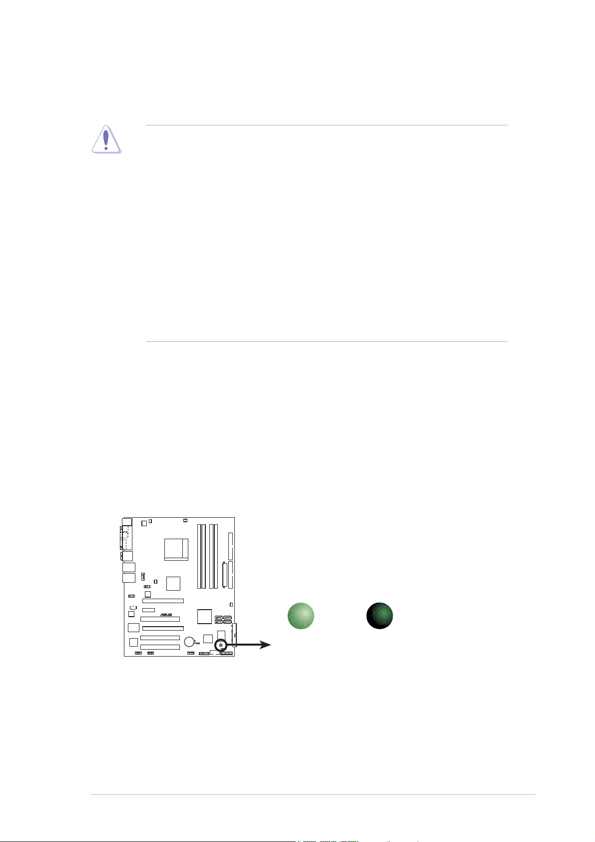
Onboard LEDOnboard LED
Onboard LED
Onboard LEDOnboard LED
The motherboard comes with a standby power LED that lights up to
indicate that the system is ON, in sleep mode, or in soft-off mode.
This is a reminder that you should shut down the system and unplug
the power cable before removing or plugging in any motherboard
component. The illustration below shows the location of the onboard
LED.
SB_PWR
®
A8R32-MVP DELUXE
A8R32-MVP DELUXE Onboard LED
ON
Standby
Power
OFF
Powered
Off
ASUS A8R32-MVP DELUXEASUS A8R32-MVP DELUXE
ASUS A8R32-MVP DELUXE
ASUS A8R32-MVP DELUXEASUS A8R32-MVP DELUXE
2-12-1
2-1
2-12-1
Page 26
2.2 Motherboard overview
Before you install the motherboard, study the configuration of your chassis
to ensure that the motherboard fits into it. Refer to the chassis
documentation before installing the motherboard.
Make sure to unplug the power cord before installing or removing the
motherboard. Failure to do so can cause you physical injury and damage
motherboard components.
2.2.12.2.1
2.2.1
2.2.12.2.1
Placement directionPlacement direction
Placement direction
Placement directionPlacement direction
When installing the motherboard, make sure that you place it into the
chassis in the correct orientation. The edge with external ports goes to the
rear part of the chassis as indicated in the image below.
2.2.22.2.2
2.2.2
2.2.22.2.2
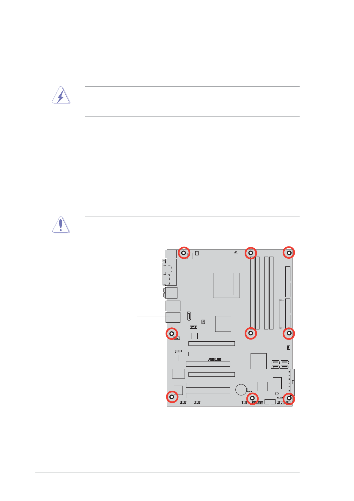
Screw holesScrew holes
Screw holes
Screw holesScrew holes
Place nine (9) screws into the holes indicated by circles to secure the
motherboard to the chassis.
Do not overtighten the screws! Doing so can damage the motherboard.
Place this side towardsPlace this side towards
Place this side towards
Place this side towardsPlace this side towards
the rear of the chassisthe rear of the chassis
the rear of the chassis
the rear of the chassisthe rear of the chassis
2-22-2
2-2
2-22-2
®
A8R32-MVP DELUXE
Chapter 2: Hardware informationChapter 2: Hardware information
Chapter 2: Hardware information
Chapter 2: Hardware informationChapter 2: Hardware information
Page 27
2.2.32.2.3
2.2.3
2.2.32.2.3
PS/2KBMS
T: Mouse
B: Keyboard
SPDIF_O
SPDIF_O2
PARALLEL PORT
ES ATA
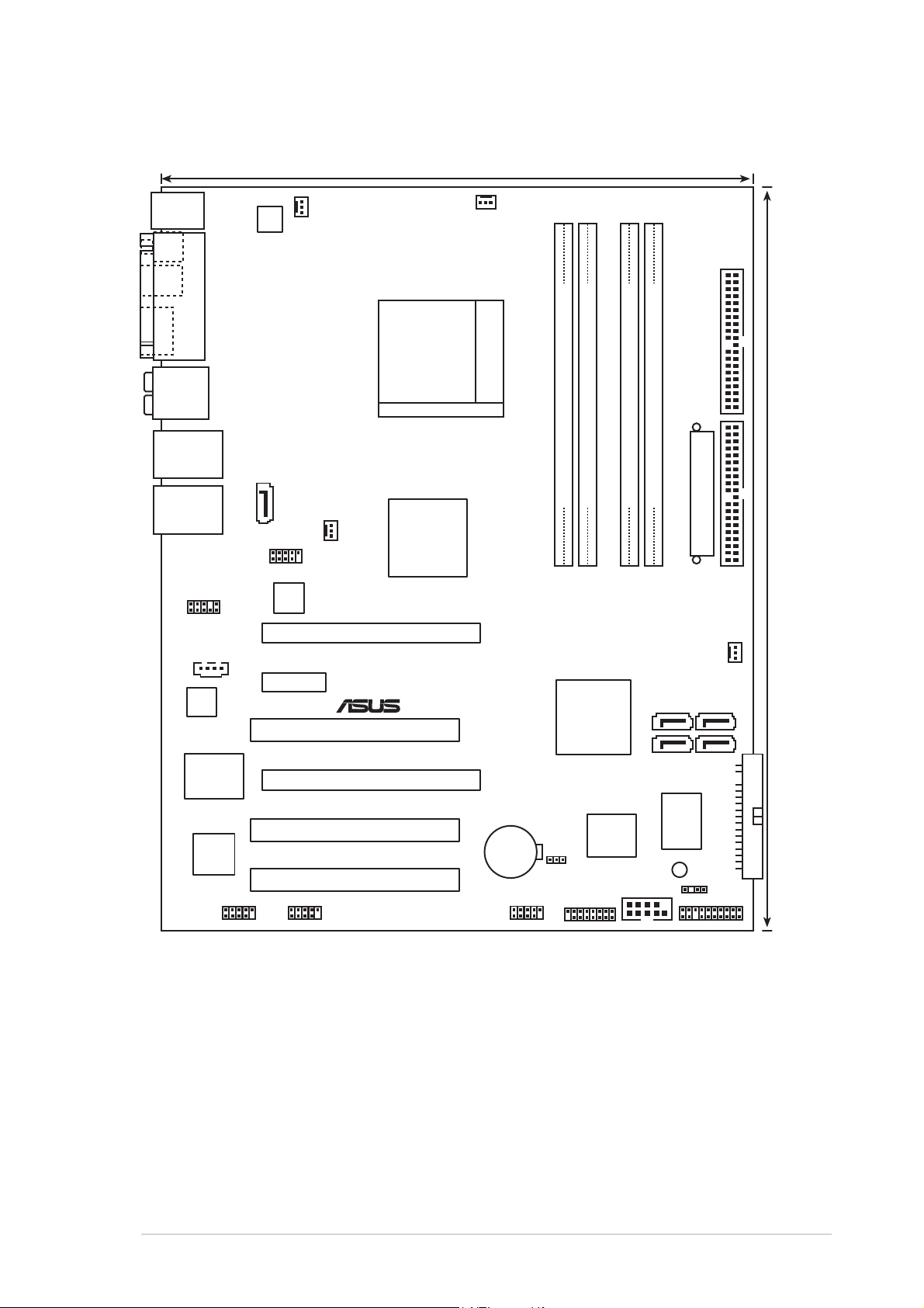
Motherboard layoutMotherboard layout
Motherboard layout
Motherboard layoutMotherboard layout
24.5cm (9.6in)
PWR_FAN
ATX12V
CPU_FAN
SEC_IDE
AUDIO
LAN1_USB12
LAN2_USB34
AAFP
ALC882
Marvell
88E8001
TSB43AB22A
SATA_RAID2
CD
IE1394_1
USB78_WFG
Marvell
88E8053
PCIEX1_1
IE1394_2
ATI™
CHA_FAN1
CrossFire™
Xpress 3200
PCIEX16_1
®
PCI1
PCIEX16_2
A8R32-MVP DELUXE
PCI2
PCI3
Socket 939
CR2032 3V
Lithium Cell
CMOS Power
CLRTC
USB56
DDR DIMM_B2 (64 bit,184-pin module)
DDR DIMM_A1 (64 bit,184-pin module)
DDR DIMM_B1 (64 bit,184-pin module)
DDR DIMM_A2 (64 bit,184-pin module)
EATXPWR
PRI_IDE
CHA_FAN2
ULI
SATA 4SATA 3
M1575
SATA 2SATA 1
FLOPPY
I/O
Super
CHASSIS
PANEL
GAME
8Mb
BIOS
SB_PWR
COM1
30.5cm (12.0in)
ASUS A8R32-MVP DELUXEASUS A8R32-MVP DELUXE
ASUS A8R32-MVP DELUXE
ASUS A8R32-MVP DELUXEASUS A8R32-MVP DELUXE
2-32-3
2-3
2-32-3
Page 28
2.2.42.2.4
2.2.4
2.2.42.2.4
Layout ContentsLayout Contents
Layout Contents
Layout ContentsLayout Contents
SlotsSlots
Slots
SlotsSlots
1. DDR DIMM slots 2-11
2. PCI slots 2-18
3. PCI Express x1 slot 2-18
4. PCI Express x16 slots 2-18
JumperJumper
Jumper
JumperJumper
1. Clear RTC RAM (3-pin CLRTC) 2-20
Rear panel connectorsRear panel connectors
Rear panel connectors
Rear panel connectorsRear panel connectors
1. PS/2 mouse port 2-21
2. Parallel port 2-21
3. Side Speaker Out port 2-21
4. Center/Subwoofer port 2-21
5. Line In port 2-21
6. Line Out port 2-21
7. LAN 1 (RJ-45) 2-22
8. LAN 2 (RJ-45) 2-22
9. USB 2.0 ports 3 and 4 2-22
10. USB 2.0 ports 1 and 2 2-22
11. Microphone port 2-22
12. Rear Speaker Out port 2-22
13. External SATA port 2-22
14. Optical S/PDIF Out port 2-22
15. Coaxial S/PDIF Out port 2-22
16. PS/2 keyboard port 2-22
PagePage
Page
PagePage
PagePage
Page
PagePage
PagePage
Page
PagePage
2-42-4
2-4
2-42-4
Chapter 2: Hardware informationChapter 2: Hardware information
Chapter 2: Hardware information
Chapter 2: Hardware informationChapter 2: Hardware information
Page 29

Internal connectorsInternal connectors
Internal connectors
Internal connectorsInternal connectors
1. Floppy disk drive connector (34-1 pin FLOPPY) 2-23
2. IDE connectors (40-1 pin PRI_IDE, 40-1 pin SEC_IDE) 2-23
3. Serial ATA connectors (7-pin SATA1 [red], SATA2 [red],
SATA3 [black], SATA4 [black]) 2-24
4. Silicon Image Serial ATA RAID connector (7-pin SATA_RAID 2) 2-26
5. CPU, Chassis, and Power fan connectors 2-27
(3-pin CPU_FAN, 3-pin CHA_FAN1, 3-pin CHA_FAN2, 3-pin PWR_FAN )
6. USB connectors (10-1 USB56, USB78_WFG) 2-28
7. Power connectors (24-pin EATXPWR, 4-pin ATX12V) 2-28
8. GAME/MIDI port connector (16-1 pin GAME) 2-29
9. Serial port connector (10-1 pin COM1) 2-30
10. IEEE 1394a connectors (10-1 pin IE1394_1; 10-1 pin IE1394_2) 2-30
11. Chassis intrusion connector (4-1 pin CHASSIS) 2-31
12. Front panel audio connector (10-1 pin AAFP) 2-32
13. Audio connector (4-pin CD [black]) 2-32
14. System panel connectors (20-1 pin PANEL) 2-33
- System Power LED (Green 3-pin PLED)
- Hard Disk activity (Red 2-pin IDE_LED)
- System warning speaker (Orange 4-pin SPEAKER)
- Power/Soft-off button(Yellow 2-pin PWRSW)
- Reset switch (Blue 2-pin RESET)
PagePage
Page
PagePage
ASUS A8R32-MVP DELUXEASUS A8R32-MVP DELUXE
ASUS A8R32-MVP DELUXE
ASUS A8R32-MVP DELUXEASUS A8R32-MVP DELUXE
2-52-5
2-5
2-52-5
Page 30
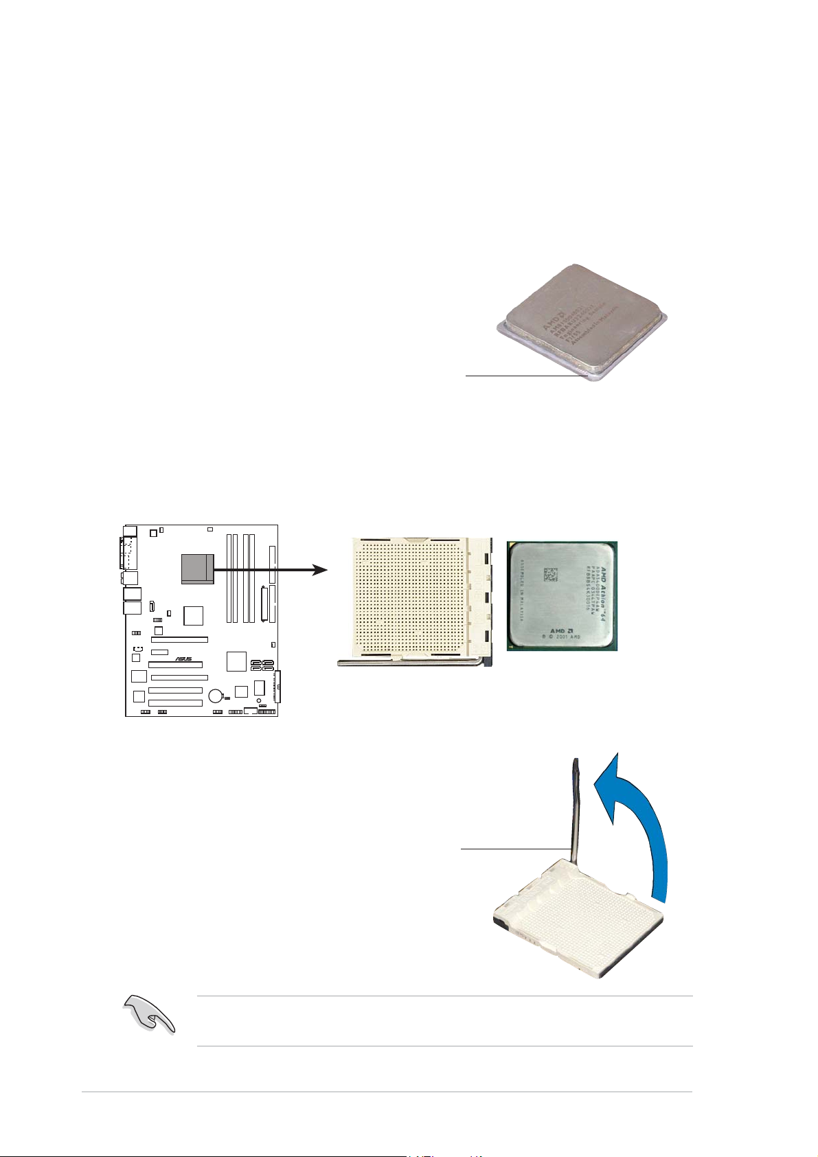
2.3 Central Processing Unit (CPU)
The motherboard comes with a surface mount 939-pin Zero Insertion Force
(ZIF) socket designed for the AMD AMD Opteron™/Athlon™ 64 X2/
Athlon™ 64 FX/Athlon™ 64 processor.
The 128-bit-wide data paths of these processors can run applications
faster than processors with only 32-bit or 64-bit wide data paths.
Take note of the marked corner (with gold
triangle) on the CPU. This mark should match
a specific corner on the socket to ensure
correct installation.
GoldGold
Gold
GoldGold
triangletriangle
triangle
triangletriangle
2.3.12.3.1
2.3.1
2.3.12.3.1
Installing the CPUInstalling the CPU
Installing the CPU
Installing the CPUInstalling the CPU
To install a CPU.
1. Locate the 939-pin ZIF socket on the motherboard.
®
A8R32-MVP DELUXE
A8R32-MVP DELUXE CPU Socket 939
2. Unlock the socket by pressing
the lever sideways, then lift it up
to a 90°-100° angle.
2-62-6
2-6
2-62-6
Socket leverSocket lever
Socket lever
Socket leverSocket lever
Make sure that the socket lever is lifted up to 90°-100° angle, otherwise
the CPU does not fit in completely.
Chapter 2: Hardware informationChapter 2: Hardware information
Chapter 2: Hardware information
Chapter 2: Hardware informationChapter 2: Hardware information
Page 31

3. Position the CPU above the
socket such that the CPU corner
with the gold triangle matches
the socket corner with a small
triangle.
4. Carefully insert the CPU into the
socket until it fits in place.
Small triangleSmall triangle
Small triangle
Small triangleSmall triangle
The CPU fits only in one correct orientation. DO NOT force the CPU into
the socket to prevent bending the pins and damaging the CPU!
5. When the CPU is in place, push
down the socket lever to secure
the CPU. The lever clicks on the
side tab to indicate that it is
locked.
Gold triangleGold triangle
Gold triangle
Gold triangleGold triangle
6. Install a CPU heatsink and fan
following the instructions that
came with the heatsink package.
ASUS A8R32-MVP DELUXEASUS A8R32-MVP DELUXE
ASUS A8R32-MVP DELUXE
ASUS A8R32-MVP DELUXEASUS A8R32-MVP DELUXE
2-72-7
2-7
2-72-7
Page 32

2.3.22.3.2
2.3.2
2.3.22.3.2
Installing the heatsink and fanInstalling the heatsink and fan
Installing the heatsink and fan
Installing the heatsink and fanInstalling the heatsink and fan
The AMD AMD Opteron™/Athlon™ 64 X2/Athlon™ 64 FX/Athlon™ 64
processor requires a specially designed heatsink and fan assembly to
ensure optimum thermal condition and performance.
Make sure that you use only AMD-certified heatsink and fan assembly.
To install the CPU heatsink and fan:
1. Place the heatsink on top of the installed CPU, making sure that the
heatsink fits properly on the retention module base.
•
The retention module base is already installed on the motherboard
upon purchase.
•
You do not have to remove the retention module base when
installing the CPU or installing other motherboard components.
•
If you purchased a separate CPU heatsink and fan assembly, make
sure that a Thermal Interface Material is properly applied to the CPU
heatsink or CPU before you install the heatsink and fan assembly.
CPU fanCPU fan
CPU fan
CPU fanCPU fan
CPU heatsinkCPU heatsink
CPU heatsink
CPU heatsinkCPU heatsink
Retention module baseRetention module base
Retention module base
Retention module baseRetention module base
Your boxed CPU heatsink and fan assembly should come with installation
instructions for the CPU, heatsink, and the retention mechanism. If the
instructions in this section do not match the CPU documentation, follow
the latter.
Retention bracketRetention bracket
Retention bracket
Retention bracketRetention bracket
Retention bracket lockRetention bracket lock
Retention bracket lock
Retention bracket lockRetention bracket lock
2-82-8
2-8
2-82-8
Chapter 2: Hardware informationChapter 2: Hardware information
Chapter 2: Hardware information
Chapter 2: Hardware informationChapter 2: Hardware information
Page 33

2. Attach one end of the retention
bracket to the retention module
base.
3. Align the other end of the
retention bracket (near the
retention bracket lock) to the
retention module base. A clicking
sound denotes that the retention
bracket is in place.
Make sure that the fan and
heatsink assembly perfectly fits
the retention mechanism module
base, otherwise you cannot snap
the retention bracket in place.
4. Push down the retention bracket
lock on the retention mechanism
to secure the heatsink and fan to
the module base.
ASUS A8R32-MVP DELUXEASUS A8R32-MVP DELUXE
ASUS A8R32-MVP DELUXE
ASUS A8R32-MVP DELUXEASUS A8R32-MVP DELUXE
2-92-9
2-9
2-92-9
Page 34

5. When the fan and heatsink assembly is in place, connect the CPU fan
cable to the connector on the motherboard labeled CPU_FAN.
CPU_FAN
GND
+12V
Rotation
®
A8R32-MVP DELUXE
A8R32-MVP DELUXE CPU fan connector
Do not forget to connect the CPU fan connector! Hardware monitoring
errors can occur if you fail to plug this connector.
2-102-10
2-10
2-102-10
Chapter 2: Hardware informationChapter 2: Hardware information
Chapter 2: Hardware information
Chapter 2: Hardware informationChapter 2: Hardware information
Page 35

2.4 System memory
2.4.12.4.1
2.4.1
2.4.12.4.1
OverviewOverview
Overview
OverviewOverview
The motherboard comes with four 184-pin Double Data Rate (DDR) Dual
Inline Memory Modules (DIMM) sockets.
The following figure illustrates the location of the sockets:
DIMM_A2
DIMM_A1
®
A8R32-MVP DELUXE
DIMM_B1
A8R32-MVP DELUXE 184-pin DDR DIMM sockets
DIMM_B2
ChannelChannel
Channel
ChannelChannel
Channel A DIMM_A1 and DIMM_A2
Channel B DIMM_B1 and DIMM_B2
In dual-channel configurations, installing
SocketsSockets
Sockets
SocketsSockets
identical identical
identical (the same type and
identical identical
size) DDR DIMM pairs for each channel provides optimum performance.
ASUS A8R32-MVP DELUXEASUS A8R32-MVP DELUXE
ASUS A8R32-MVP DELUXE
ASUS A8R32-MVP DELUXEASUS A8R32-MVP DELUXE
2-112-11
2-11
2-112-11
Page 36

2.4.22.4.2
2.4.2
2.4.22.4.2
Memory ConfigurationsMemory Configurations
Memory Configurations
Memory ConfigurationsMemory Configurations
You may install 256 MB, 512 MB, and 1 GB unbuffered ECC/non-ECC DDR
DIMMs into the DIMM sockets using the memory configurations in this
section.
•
If you installed four 1 GB memory modules, the system may detect
less than 3 GB of total memory because of address space allocation
for other critical functions. This limitation applies to Windows
32-bit version operating system since it does not support Physical
Address Extension (PAE).
• When using only one DDR DIMM module, install it into slot DIMM_B1
only.
• For single-channel memory configuration, start installing the DDR
DIMMs from slot DIMM_B1 or DMM_B2.
•
For dual-channel memory configuration, install the DIMMs in slots
DIMM_B1 and DIMM_A1 (blue slots); install another pair of DIMMs in
slots DIMM_B2 and DIMM_A2 (black slots).
• Always install DIMMs with the same CAS latency. For optimum
results, we recommend that you obtain memory modules from the
same vendor. Refer to the Qualified Vendors List on the next page
for details.
®
XP
• When you install four double-sided 400 MHz DDR DIMMs, the
frequency of each module downgrades to 333 MHz.
Recommended memory configurationsRecommended memory configurations
Recommended memory configurations
Recommended memory configurationsRecommended memory configurations
SocketsSockets
Sockets
SocketsSockets
ModeMode
Mode
ModeMode
Single-channel (1) – – Populated –
Dual-channel* (1) Populated – Populated –
(2) Populated Populated Populated Populated
* Use only identical DDR DIMM pairs.* Use only identical DDR DIMM pairs.
* Use only identical DDR DIMM pairs.
* Use only identical DDR DIMM pairs.* Use only identical DDR DIMM pairs.
* For dual-channel configuration (2), you may:* For dual-channel configuration (2), you may:
* For dual-channel configuration (2), you may:
* For dual-channel configuration (2), you may:* For dual-channel configuration (2), you may:
install identical DIMMs in all four sockets
•
OROR
OR
OROR
•
install identical DIMM pair in DIMM_A1 and DIMM_B1 (blue sockets)
DIMM_A1DIMM_A1
DIMM_A1
DIMM_A1DIMM_A1
DIMM_A2DIMM_A2
DIMM_A2
DIMM_A2DIMM_A2
DIMM_B1DIMM_B1
DIMM_B1
DIMM_B1DIMM_B1
DIMM_B2DIMM_B2
DIMM_B2
DIMM_B2DIMM_B2
2-122-12
2-12
2-122-12
Chapter 2: Hardware informationChapter 2: Hardware information
Chapter 2: Hardware information
Chapter 2: Hardware informationChapter 2: Hardware information
Page 37

DDR (400 MHz) Qualified Vendors ListDDR (400 MHz) Qualified Vendors List
DDR (400 MHz) Qualified Vendors List
DDR (400 MHz) Qualified Vendors ListDDR (400 MHz) Qualified Vendors List
DIMM supportDIMM support
DIMM support
DIMM supportDIMM support
SizeSize
Size
SizeSize
256 MB TwinMOS TMD7608F8E50D TwinMOS SS M2G9I08AIATT9F081AADT • •
512 MB TwinMOS TMD7608F8E50D TwinMOS DS M2G9J16AJATT9F081AADT • • •
256 MB TwinMOS TMD7608F8E50D TwinMOS DS M2G9I08A8ATT9F081AADT • • •
512 MB TwinMOS TMD7608F8E50D TwinMOS SS M2G9J16AJATT9F081AADT • • •
256 MB TwinMOS TMD7608F8E50I TwinMOS SS M2G9I08A8ATT9F081CADT • •
256 MB V-DATA VDD9616A8A-5C N/A SS MDYVD6F4G2880B1E0H • •
256 MB Winbond W942508CH-5 Winbond DS W9425GCDB-5 • • •
512 MB Winbond W942508CH-5 Winbond DS W9451GCDB-5 • • •
256 MB GEIL GL3LC32G88TG-35 N/A SS GL5123200DC • • •
256 MB GEIL GL3LC32G88TG-5A N/A SS GLX2563200UP • •
256 MB PSC A2S56D30BTP PSC SS AL5D8B53T-5B1K • • •
512 MB PSC A2S56D30BTP PSC DS AL6D8B53T-5B1K • •
256 MB NANYA NT5DS32M8CT-5T N/A DS NT256D64S88C0G-5T • •
512 MB NANYA NT5DS32M8CT-5T N/A DS NT512D64S8HC0G-5T • • •
256 MB NANYA NT5DS32M16BT-5T N/A DS NT256D64SH4B0G-5T • •
512 MB NANYA NT5DS64M8BT-5T N/A SS NT512D64S88B0G-5T • • •
1024 MB NANYA NT5DS64M8BT-5T N/A DS NT1GD64S8HB0G-5T • • •
512 MB NANYA NT5DS64M8CS-5T N/A SS NT512D64S88C0GY-5T • • •
256 MB Novax C2S56D30TP-5 CEON DS 96M425653CE-40TB6 • • •
512 MB Novax C2S56D30TP-5 CEON DS 96M451253CE-40TB6 • • •
256 MB CENTURY K4H560838E-TCCC N/A DS DXV6S8SSCCE3K27E • • •
512 MB CENTURY K4H560838E-TCCC N/A DS DXV2S8SSCCE3K27E •
256 MB CENTURY DD2508AMTA N/A DS DXV6S8EL5BM3T27C • • •
512 MB CENTURY DD2508AMTA N/A DS DXV2S8EL5BM3T27C • • •
256 MB CENTURY DD2508AMTA N/A DS DXV6S8EL5B • • •
256 MB CENTURY HY5DU56822BT-D43 N/A DS DXV6S8HXD43B • • •
256 MB CENTURY HY5DU56822DT-D43 N/A DS DXV6S8HXD43D • • •
512 MB CENTURY DD2508AMTA N/A DS DXV2S8EL5B • •
512 MB CENTURY HY5DU56822BT-D43 N/A DS DXV2S8HXD43B • •
512 MB CENTURY HY5DU56822DT-D43 N/A DS DXV2S8HXD43D • • •
256 MB CENTURY DD2508AKTA-5B-E N/A DS DXV6S8EL5B/HP • • •
512 MB CENTURY DD2508AKTA-5B-E N/A DS DXV2S8EL5B/HP • • •
256 MB CENTURY MT46V32M8TG-5BG N/A DS DXV6S8MC5B • •
512 MB CENTURY HY5DU12822CTP-D43 N/A DS DXV2H8 • • •
1024 MB CENTURY HY5DU12822CTP-D43 N/A DS DXV0H8 • •
256 MB Elixir N2DS25680CT-5T N/A DS M2U25664DS88C3G-5T • • •
512 MB Elixir N2DS25680CT-5T N/A DS M2U51264DS8HC3G-5T • • •
512 MB Elixir N2DS51280BT-5T N/A DS M2U51264DS88B1G-5T • • •
256 MB Kreton VT3225804T-5 VT DS N/A • • •
512 MB Kreton VT3225804T-5 VT DS N/A • •
256 MB Veritech VT56DD32M8PC-5 VM DS VU256FLTM25C • • •
512 MB Veritech VT56DD32M8PC-5 VM DS VU512FLTM25C • •
256 MB Pmi V58C2256804SAT5B MOSEL DS MD44256VIT3208GMHA01 • •
512 MB Pmi V58C2256804SAT5B MOSEL DS MD44512VIT3208GATA03 • • •
VendorVendor
Vendor
VendorVendor
Chip No.Chip No.
Chip No.
Chip No.Chip No.
BrandBrand
Brand
BrandBrand
Side/s*Side/s*
Side/s*
Side/s*Side/s*
Part No.Part No.
Part No.
Part No.Part No.
AA
BB
A
B
AA
BB
CC
C
CC
(Continued on the next page)
ASUS A8R32-MVP DELUXEASUS A8R32-MVP DELUXE
ASUS A8R32-MVP DELUXE
ASUS A8R32-MVP DELUXEASUS A8R32-MVP DELUXE
2-132-13
2-13
2-132-13
Page 38

DDR (400 MHz) Qualified Vendors ListDDR (400 MHz) Qualified Vendors List
DDR (400 MHz) Qualified Vendors List
DDR (400 MHz) Qualified Vendors ListDDR (400 MHz) Qualified Vendors List
DIMM supportDIMM support
DIMM support
DIMM supportDIMM support
SizeSize
Size
SizeSize
256 MB ProMOS V58C2256804SCT5B N/A SS V826632K24SCTG-D0 • • •
512 MB ProMOS V58C2256804SCT5B N/A DS V826664K24SCTG-D0 • •
512 MB Deutron A2S56D30CTP PSC DS AL6D8C53T-5B1T • •
256 MB Aeneon AED83T500 Aeneon SS AED560UD00-500C88Z • • •
512 MB Aeneon AED93T500 Aeneon SS AED560UD00-500B98X • • •
512 MB Aeneon AED83T500 Aeneon DS AED560UD00-500C88X • • •
256 MB SimpleTech 838S032T05A N/A SS SVM-DDR3200/256 • •
512 MB SimpleTech 838S032T05A N/A DS SVM-DDR3200/512 • • •
1024 MB Patriot Heat-Sink Package N/A DS PDC1G3200+XBLK • • •
512 MB MDT 25B25680-50520 N/A DS M512-400-16B • •
Legend:Legend:
Legend:
Legend:Legend:
A A
A - supports one module inserted in DIMM_B1 slot in a Single-channel memory
A A
VendorVendor
Vendor
VendorVendor
Chip No.Chip No.
Chip No.
Chip No.Chip No.
BrandBrand
Brand
BrandBrand
Side/s*Side/s*
Side/s*
Side/s*Side/s*
Part No.Part No.
Part No.
Part No.Part No.
AA
BB
CC
A
B
C
AA
BB
CC
configuration.
BB
B - Supports one pair of modules inserted into either the blue slots or the black
BB
slots as one pair of Dual-channel memory configuration.
C C
C - Supports 3 modules inserted into both the blue and black slots as two pairs of
C C
Dual-channel memory configuration
SSSS
S S - Single-sided
SSSS
DSDS
D S - Double-sided
DSDS
Visit the ASUS website (www.asus.com) for the latest Qualified Vendors
List.
2-142-14
2-14
2-142-14
Chapter 2: Hardware informationChapter 2: Hardware information
Chapter 2: Hardware information
Chapter 2: Hardware informationChapter 2: Hardware information
Page 39

2.4.32.4.3
2.4.3
2.4.32.4.3
Installing a DDR DIMMInstalling a DDR DIMM
Installing a DDR DIMM
Installing a DDR DIMMInstalling a DDR DIMM
Make sure to unplug the power supply before adding or removing DIMMs
or other system components. Failure to do so may cause severe damage
to both the motherboard and the components.
1. Unlock a DIMM socket by
pressing the retaining clips
outward.
2. Align a DIMM on the socket such
that the notch on the DIMM
matches the break on the
socket.
2
DDR DIMM notchDDR DIMM notch
DDR DIMM notch
DDR DIMM notchDDR DIMM notch
1
1
Unlocked retaining clipUnlocked retaining clip
Unlocked retaining clip
Unlocked retaining clipUnlocked retaining clip
A DDR DIMM is keyed with a notch so that it fits in only one direction.
DO NOT force a DIMM into a socket to avoid damaging the DIMM.
3. Firmly insert the DIMM into the
socket until the retaining clips
snap back in place and the DIMM
is properly seated.
2.4.42.4.4
2.4.4
2.4.42.4.4
Removing a DDR DIMMRemoving a DDR DIMM
Removing a DDR DIMM
Removing a DDR DIMMRemoving a DDR DIMM
To remove a DIMM:
1. Simultaneously press the
retaining clips outward to unlock
the DIMM.
Locked Retaining ClipLocked Retaining Clip
Locked Retaining Clip
Locked Retaining ClipLocked Retaining Clip
2
1
1
Support the DIMM lightly with your fingers when pressing the retaining
clips. The DIMM might get damaged when it flips out with extra force.
2. Remove the DIMM from the socket.
ASUS A8R32-MVP DELUXEASUS A8R32-MVP DELUXE
ASUS A8R32-MVP DELUXE
ASUS A8R32-MVP DELUXEASUS A8R32-MVP DELUXE
DDR DIMM notchDDR DIMM notch
DDR DIMM notch
DDR DIMM notchDDR DIMM notch
2-152-15
2-15
2-152-15
Page 40

2.5 Expansion slots
In the future, you may need to install expansion cards. The following
sub-sections describe the slots and the expansion cards that they support.
Make sure to unplug the power cord before adding or removing
expansion cards. Failure to do so may cause you physical injury and
damage motherboard components.
2.5.12.5.1
2.5.1
2.5.12.5.1
To install an expansion card:
1. Before installing the expansion card, read the documentation that
came with it and make the necessary hardware settings for the card.
2. Remove the system unit cover (if your motherboard is already
installed in a chassis).
3. Remove the bracket opposite the slot that you intend to use. Keep
the screw for later use.
4. Align the card connector with the slot and press firmly until the card is
completely seated on the slot.
5. Secure the card to the chassis with the screw you removed earlier.
6. Replace the system cover.
2.5.22.5.2
2.5.2
2.5.22.5.2
After installing the expansion card, configure it by adjusting the software
settings.
Installing an expansion cardInstalling an expansion card
Installing an expansion card
Installing an expansion cardInstalling an expansion card
Configuring an expansion cardConfiguring an expansion card
Configuring an expansion card
Configuring an expansion cardConfiguring an expansion card
1. Turn on the system and change the necessary BIOS settings, if any.
See Chapter 4 for information on BIOS setup.
2. Assign an IRQ to the card. Refer to the tables on the next page.
3. Install the software drivers for the expansion card.
2-162-16
2-16
2-162-16
Chapter 2: Hardware informationChapter 2: Hardware information
Chapter 2: Hardware information
Chapter 2: Hardware informationChapter 2: Hardware information
Page 41

2.5.32.5.3
2.5.3
2.5.32.5.3
Standard interrupt assignmentsStandard interrupt assignments
Standard interrupt assignments
Standard interrupt assignmentsStandard interrupt assignments
Interrupt assignmentsInterrupt assignments
Interrupt assignments
Interrupt assignmentsInterrupt assignments
IRQIRQ
IRQ
IRQIRQ
0 1 System Timer
1 2 Keyboard Controller
2 — Re-direct to IRQ #9
3 11 Reserved
4 12 Communications Port (COM1)*
5 13 IRQ holder for PCI steering*
6 14 Floppy Disk Controller
7 15 Printer Port (LPT1)*
8 3 System CMOS/Real Time Clock
9 4 IRQ holder for PCI steering*
10 5 IRQ holder for PCI steering*
11 6 IRQ holder for PCI steering*
12 7 PS/2 Compatible Mouse Port*
13 8 Numeric Data Processor
14 9 Primary IDE/SATA Channel
15 10 Secondary IDE/SATA Channel
* These IRQs are usually available for ISA or PCI devices.* These IRQs are usually available for ISA or PCI devices.
* These IRQs are usually available for ISA or PCI devices.
* These IRQs are usually available for ISA or PCI devices.* These IRQs are usually available for ISA or PCI devices.
PriorityPriority
Priority
PriorityPriority
Standard FunctionStandard Function
Standard Function
Standard FunctionStandard Function
IRQ assignments for this motherboardIRQ assignments for this motherboard
IRQ assignments for this motherboard
IRQ assignments for this motherboardIRQ assignments for this motherboard
AA
A
AA
PCI slot 1 — shared shared shared shared — — —
PCI slot 2 — — shared shared shared shared — —
PCI slot 3 — — — shared shared shared shared —
IEEE 1394 — — — — shared — — —
PCI Express LAN (88E8053) — — shared — ————
PCI LAN (88E8001) — — — — — shared — —
PCI-E x1 shared shared shared shared ————
PCI-E x16_1 shared shared shared shared ————
PCI-E x16_2 shared shared shared shared ————
Onboard USB controller 1 — shared — — ————
Onboard USB controller 2 — — shared — ————
Onboard USB controller 3 — — — shared ————
Onboard USB 2.0 controller — — — shared ————
HD audio — — — — — — shared —
Serial ATA — — — shared ————
Silicon Image SATA controller — shared — — ————
BB
B
BB
CC
C
CC
DD
D
DD
EE
E
EE
FF
F
FF
GG
G
GG
HH
H
HH
When using PCI cards on shared slots, ensure that the drivers support
“Share IRQ” or that the cards do not need IRQ assignment; otherwise,
conflicts will arise between the two PCI groups, making the system
unstable and the card inoperable.
ASUS A8R32-MVP DELUXEASUS A8R32-MVP DELUXE
ASUS A8R32-MVP DELUXE
ASUS A8R32-MVP DELUXEASUS A8R32-MVP DELUXE
2-172-17
2-17
2-172-17
Page 42

2.5.42.5.4
2.5.4
2.5.42.5.4
The PCI slots support cards such as a
LAN card, SCSI card, USB card, and
other cards that comply with PCI
specifications. The figure shows a
LAN card installed on a PCI slot.
PCI slotsPCI slots
PCI slots
PCI slotsPCI slots
2.5.52.5.5
2.5.5
2.5.52.5.5
This motherboard supports PCI
Express x1 network cards, SCSI cards
and other cards that comply with the
PCI Express specifications. The
following figure shows a network card
installed on the PCI Express x1 slot.
2.5.62.5.6
2.5.6
2.5.62.5.6
This motherboard supports two ATI
CrossFire™ PCI Express x16 graphics
cards that comply with the PCI
Express specifications. The figure
shows two graphics cards installed on
the PCI Express x16 slots.
PCI Express x1 slotPCI Express x1 slot
PCI Express x1 slot
PCI Express x1 slotPCI Express x1 slot
Two PCI Express x16 slotsTwo PCI Express x16 slots
Two PCI Express x16 slots
Two PCI Express x16 slotsTwo PCI Express x16 slots
See Chapter 6 for details on the
CrossFire™ technology feature.
2-182-18
2-18
2-182-18
Chapter 2: Hardware informationChapter 2: Hardware information
Chapter 2: Hardware information
Chapter 2: Hardware informationChapter 2: Hardware information
Page 43
• We recommend that you install a VGA card on the primary (blue) PCI
Express slot and install any other PCI Express device on the
secondary (black) PCI Express slot.
In CrossFire™ mode, install the ATI CrossFire™ EditionIn CrossFire™ mode, install the ATI CrossFire™ Edition
•
In CrossFire™ mode, install the ATI CrossFire™ Edition
In CrossFire™ mode, install the ATI CrossFire™ EditionIn CrossFire™ mode, install the ATI CrossFire™ Edition
(Master) graphics card on the primary (blue) PCI(Master) graphics card on the primary (blue) PCI
(Master) graphics card on the primary (blue) PCI
(Master) graphics card on the primary (blue) PCI(Master) graphics card on the primary (blue) PCI
Express slot; otherwise, the system will not boot.Express slot; otherwise, the system will not boot.
Express slot; otherwise, the system will not boot.
Express slot; otherwise, the system will not boot.Express slot; otherwise, the system will not boot.
• If you do not configure the PCI Express device (s) according to the
table below, the system may have a failed or delayed power-on self
test (POST).
• Refer to the table below for possible PCI Express Card
configurations.
PCI Express x16 slot configurationsPCI Express x16 slot configurations
PCI Express x16 slot configurations
PCI Express x16 slot configurationsPCI Express x16 slot configurations
Single
graphics
card
Dual
graphics
cards in
CrossFire™
mode*
Dual
graphics
cards (Dual
display)
PCIEX16_1 (blue) slotPCIEX16_1 (blue) slot
PCIEX16_1 (blue) slot
PCIEX16_1 (blue) slotPCIEX16_1 (blue) slot
Card TypeCard Type
Card Type
Card TypeCard Type
PCIe x16 graphics card x16
PCIe x16 graphics card x16 PCIe devices (non-VGA) x16
ATI CrossFire Edition x16 ATI CrossFire-ready x16
graphics card graphics card
Graphics card x16 Graphics card x16
SpeedSpeed
Speed
SpeedSpeed
PCIEX16_2 (black) slotPCIEX16_2 (black) slot
PCIEX16_2 (black) slot
PCIEX16_2 (black) slotPCIEX16_2 (black) slot
Card TypeCard Type
Card Type
Card TypeCard Type
SpeedSpeed
Speed
SpeedSpeed
* In CrossFire™ mode, install two ATI graphics cards from the same
GPU family.
ASUS A8R32-MVP DELUXEASUS A8R32-MVP DELUXE
ASUS A8R32-MVP DELUXE
ASUS A8R32-MVP DELUXEASUS A8R32-MVP DELUXE
2-192-19
2-19
2-192-19
Page 44

2.6 Jumper
Clear RTC RAM (CLRTC)Clear RTC RAM (CLRTC)
Clear RTC RAM (CLRTC)
Clear RTC RAM (CLRTC)Clear RTC RAM (CLRTC)
This jumper allows you to clear the Real Time Clock (RTC) RAM in CMOS.
You can clear the CMOS memory of date, time, and system setup
parameters by erasing the CMOS RTC RAM data. The onboard button cell
battery powers the RAM data in CMOS, which include system setup
information such as system passwords.
To erase the RTC RAM:
1. Turn OFF the computer and unplug the power cord.
2. Remove the onboard battery.
3. Move the jumper cap from pins 1-2 (default) to pins 2-3. Keep the
cap on pins 2-3 for about 5~10 seconds, then move the cap back to
pins 1-2.
4. Reinstall the battery.
5. Plug the power cord and turn ON the computer.
6. Hold down the <Del> key during the boot process and enter BIOS
setup to re-enter data.
Except when clearing the RTC RAM, never remove the cap on CLRTC
jumper default position. Removing the cap will cause system boot failure!
CLRTC
®
A8R32-MVP DELUXE
A8R32-MVP DELUXE Clear RTC RAM
You do not need to clear the RTC when the system hangs due to
overclocking. For system failure due to overclocking, use the C.P.R. (CPU
Parameter Recall) feature. Shut down and reboot the system so the BIOS
can automatically reset parameter settings to default values.
12 23
Normal Clear CMOS
(Default)
2-202-20
2-20
2-202-20
Chapter 2: Hardware informationChapter 2: Hardware information
Chapter 2: Hardware information
Chapter 2: Hardware informationChapter 2: Hardware information
Page 45

2.7 Connectors
2.7.12.7.1
2.7.1
2.7.12.7.1
1.1.
PS/2 mouse port (green).PS/2 mouse port (green).
1.
PS/2 mouse port (green). This port is for a PS/2 mouse.
1.1.
PS/2 mouse port (green).PS/2 mouse port (green).
2.2.
Parallel port.Parallel port.
2.
Parallel port. This 25-pin port connects a parallel printer, a scanner,
2.2.
Parallel port.Parallel port.
Rear panel connectorsRear panel connectors
Rear panel connectors
Rear panel connectorsRear panel connectors
1
16
15 14 10
2
13
73 5 6
1112
84
9
or other devices.
3.3.
Side Speaker Out port (black). Side Speaker Out port (black).
3.
Side Speaker Out port (black). This port connects the side
3.3.
Side Speaker Out port (black). Side Speaker Out port (black).
speakers in an 8-channel audio configuration.
4.4.
Center/Subwoofer port (orange). Center/Subwoofer port (orange).
4.
Center/Subwoofer port (orange). This port connects the
4.4.
Center/Subwoofer port (orange). Center/Subwoofer port (orange).
center/subwoofer speakers.
5.5.
Line In port (light blue).Line In port (light blue).
5.
Line In port (light blue). This port connects a tape, CD, DVD
5.5.
Line In port (light blue).Line In port (light blue).
player, or other audio sources.
6.6.
Line Out port (lime).Line Out port (lime).
6.
Line Out port (lime). This port connects a headphone or a
6.6.
Line Out port (lime).Line Out port (lime).
speaker. In 4-channel, 6-channel, and 8-channel configuration, the
function of this port becomes Front Speaker Out.
Refer to the audio configuration table below for the function of the
audio ports in 2, 4, or 6, or 8-channel configuration.
Audio 2, 4, 6, or 8-channel configurationAudio 2, 4, 6, or 8-channel configuration
Audio 2, 4, 6, or 8-channel configuration
Audio 2, 4, 6, or 8-channel configurationAudio 2, 4, 6, or 8-channel configuration
PortPort
Port
PortPort
Light Blue Line In Line In Line In Line In
Lime Line Out Front Speaker Out Front Speaker Out Front Speaker Out
Pink Mic In Mic In Mic In Mic In
Gray • Rear Speaker Out Rear Speaker Out Rear Speaker Out
Black • • • Side Speaker Out
Orange • • Center/Subwoofer Center/Subwoofer
HeadsetHeadset
Headset
HeadsetHeadset
2-channel2-channel
2-channel
2-channel2-channel
4-channel4-channel
4-channel
4-channel4-channel
6-channel6-channel
6-channel
6-channel6-channel
8-channel8-channel
8-channel
8-channel8-channel
ASUS A8R32-MVP DELUXEASUS A8R32-MVP DELUXE
ASUS A8R32-MVP DELUXE
ASUS A8R32-MVP DELUXEASUS A8R32-MVP DELUXE
2-212-21
2-21
2-212-21
Page 46

LAN 1 (RJ-45) port.LAN 1 (RJ-45) port.
7.7.
LAN 1 (RJ-45) port. Supported by Marvell
7.
7.7.
LAN 1 (RJ-45) port.LAN 1 (RJ-45) port.
®
Gigabit LAN controller,
this port allows Gigabit connection to a Local Area Network (LAN)
through a network hub. Refer to the table below for the LAN port LED
indications.
8.8.
LAN 2 (RJ-45) port.LAN 2 (RJ-45) port.
8.
LAN 2 (RJ-45) port. Supported by the Marvell
8.8.
LAN 2 (RJ-45) port.LAN 2 (RJ-45) port.
®
Gigabit LAN
controller, this port allows Gigabit connection to a Local Area Network
(LAN) through a network hub.
32-bit OS LAN port LED indications32-bit OS LAN port LED indications
32-bit OS LAN port LED indications
32-bit OS LAN port LED indications32-bit OS LAN port LED indications
ACTIVITY/
Activity/LinkActivity/Link
Activity/Link
Activity/LinkActivity/Link
OFF OFF Soft-off Mode
YELLOW* OFF During Power ON/OFF
YELLOW* ORANGE 100 Mbps connection
YELLOW* GREEN 1 Gbps connection
* Blinking
9.9.
USB 2.0 ports 3 and 4.USB 2.0 ports 3 and 4.
9.
USB 2.0 ports 3 and 4. These two 4-pin Universal Serial Bus
9.9.
USB 2.0 ports 3 and 4.USB 2.0 ports 3 and 4.
Speed LEDSpeed LED
Speed LED
Speed LEDSpeed LED
DescriptionDescription
Description
DescriptionDescription
LINK LED
SPEED
LED
LAN port
(USB) ports are available for connecting USB 2.0 devices.
10.10.
USB 2.0 ports 1 and 2.USB 2.0 ports 1 and 2.
10.
USB 2.0 ports 1 and 2. These two 4-pin Universal Serial Bus
10.10.
USB 2.0 ports 1 and 2.USB 2.0 ports 1 and 2.
(USB) ports are available for connecting USB 2.0 devices.
11.11.
Microphone port (pink)Microphone port (pink)
11.
Microphone port (pink). This port connects a microphone.
11.11.
Microphone port (pink)Microphone port (pink)
12.12.
Rear Speaker Out port (gray). Rear Speaker Out port (gray).
12.
Rear Speaker Out port (gray). This port connects the rear
12.12.
Rear Speaker Out port (gray). Rear Speaker Out port (gray).
speakers on a 4-channel, 6-channel, or 8-channel audio configuration.
13.13.
External SATA port.External SATA port.
13.
External SATA port. This port connects to an external SATA box
13.13.
External SATA port.External SATA port.
or a Serial ATA port multiplier.
The external SATA port
supports external Serial ATA
1.5 and 3 Gb/s devices. Longer
cables support higher power
requirements to deliver signal
up to two meters away, and
enables improved hot-swap
function.
Do not insert a different
connector to this port.
14.14.
Optical S/PDIF Out port. Optical S/PDIF Out port.
14.
Optical S/PDIF Out port. This port connects an external audio
14.14.
Optical S/PDIF Out port. Optical S/PDIF Out port.
output device via an optical S/PDIF cable.
2-222-22
2-22
2-222-22
15.15.
Coaxial S/PDIF Out port. Coaxial S/PDIF Out port.
15.
Coaxial S/PDIF Out port. This port connects an external audio
15.15.
Coaxial S/PDIF Out port. Coaxial S/PDIF Out port.
output device via a coaxial S/PDIF cable.
16.16.
PS/2 keyboard port (purple).PS/2 keyboard port (purple).
16.
PS/2 keyboard port (purple). This port is for a PS/2 keyboard.
16.16.
PS/2 keyboard port (purple).PS/2 keyboard port (purple).
Chapter 2: Hardware informationChapter 2: Hardware information
Chapter 2: Hardware information
Chapter 2: Hardware informationChapter 2: Hardware information
Page 47

2.7.22.7.2
2.7.2
2.7.22.7.2
1.1.
Floppy disk drive connector (34-1 pin FLOPPY)Floppy disk drive connector (34-1 pin FLOPPY)
1.
Floppy disk drive connector (34-1 pin FLOPPY)
1.1.
Floppy disk drive connector (34-1 pin FLOPPY)Floppy disk drive connector (34-1 pin FLOPPY)
Internal connectorsInternal connectors
Internal connectors
Internal connectorsInternal connectors
This connector is for the provided floppy disk drive (FDD) signal cable.
Insert one end of the cable to this connector, then connect the other
end to the signal connector at the back of the floppy disk drive.
Pin 5 on the connector is removed to prevent incorrect cable connection
when using an FDD cable with a covered Pin 5.
PIN 1
®
A8R32-MVP DELUXE
FLOPPY
NOTE: Orient the red markings on
the floppy ribbon cable to PIN 1.
A8R32-MVP DELUXE Floppy disk drive connector
2.2.
IDE connectors (40-1 pin PRI_IDE; 40-1 pin SEC_IDE)IDE connectors (40-1 pin PRI_IDE; 40-1 pin SEC_IDE)
2.
IDE connectors (40-1 pin PRI_IDE; 40-1 pin SEC_IDE)
2.2.
IDE connectors (40-1 pin PRI_IDE; 40-1 pin SEC_IDE)IDE connectors (40-1 pin PRI_IDE; 40-1 pin SEC_IDE)
The onboard IDE connectors are for Ultra DMA (133/)100/66 signal
cable(s). There are three connectors on each Ultra DMA 133/100/66
signal cable: blue, black, and gray. Connect the blue connector to the
motherboard's IDE connector, then select one of the following modes
to configure your device(s).
Drive jumperDrive jumper
Drive jumper
Drive jumperDrive jumper
settingsetting
setting
settingsetting
Single device Cable-Select or Master - Black
Two devices Cable-Select Master Black
Master Master
Slave Slave
ModeMode
Mode
ModeMode
of device(s)of device(s)
of device(s)
of device(s)of device(s)
Slave Gray
CableCable
Cable
CableCable
connectorconnector
connector
connectorconnector
Black or gray
• Pin 20 on the IDE connector is removed to match the covered hole
on the Ultra DMA cable connector. This prevents incorrect insertion
when you connect the IDE cable.
• Use the 80-conductor IDE cable for Ultra DMA 100/66 IDE devices.
If any device jumper is set as "Cable-Select," make sure all other device
jumpers have the same setting.
ASUS A8R32-MVP DELUXEASUS A8R32-MVP DELUXE
ASUS A8R32-MVP DELUXE
ASUS A8R32-MVP DELUXEASUS A8R32-MVP DELUXE
2-232-23
2-23
2-232-23
Page 48

NOTE: Orient the red markings
(usually zigzag) on the IDE
ribbon cable to PIN 1.
®
A8R32-MVP DELUXE
SEC_IDE
PIN 1
PRI_IDE
PIN 1
A8R32-MVP DELUXE IDE connectors
3.3.
Serial ATA connectorsSerial ATA connectors
3.
Serial ATA connectors
3.3.
Serial ATA connectorsSerial ATA connectors
(7-pin SATA1 [red], SATA2 [red], SATA3 [black],(7-pin SATA1 [red], SATA2 [red], SATA3 [black],
(7-pin SATA1 [red], SATA2 [red], SATA3 [black],
(7-pin SATA1 [red], SATA2 [red], SATA3 [black],(7-pin SATA1 [red], SATA2 [red], SATA3 [black],
SATA4 [black])SATA4 [black])
SATA4 [black])
SATA4 [black])SATA4 [black])
These connectors are for the Serial ATA signal cables for Serial ATA
hard disk drives.
If you installed Serial ATA hard disk drives, you can can create a
RAID 0, RAID 1, RAID 0+1, RAID 5, and JBOD configuration. Refer to
Chapter 5 for information on creating a RAID configuration.
Enable the
Serial ATA Controller Serial ATA Controller
Serial ATA Controller and
Serial ATA Controller Serial ATA Controller
items in the BIOS if you want to use the Serial ATA RAID feature. See
section “4.3.6 Storage Configuration” for details.
Onboard SATA Boot ROMOnboard SATA Boot ROM
Onboard SATA Boot ROM
Onboard SATA Boot ROMOnboard SATA Boot ROM
2-242-24
2-24
2-242-24
RSATA_RXP3
GND
GND
RSATA_TXP3
RSATA_RXN3
RSATA_TXN3
SATA3 SATA4
®
A8R32-MVP DELUXE
GND
RSATA_RXP1
RSATA_RXN1
GND
RSATA_TXP1
RSATA_TXN1
SATA1 SATA2
A8R32-MVP DELUXE SATA connectors
Chapter 2: Hardware informationChapter 2: Hardware information
Chapter 2: Hardware information
Chapter 2: Hardware informationChapter 2: Hardware information
GND
GND
GND
GND
RSATA_RXP4
RSATA_RXN4
RSATA_RXP2
RSATA_RXN2
GND
GND
RSATA_TXP4
RSATA_TXN4
RSATA_TXP2
RSATA_TXN2
GND
GND
Page 49

• Plug your Serial ATA boot disk on the master port (SATA1/2 to
support S3 function).
• Install the Windows
®
2000 Service Pack 4 or the Windows® XP
Service Pack1 or later when using Serial ATA.
• In RAID mode, the system cannot boot from a SATA CD-ROM which
is connected with the ULi M1575 controller.
Serial ATA hard disk drive connectionSerial ATA hard disk drive connection
Serial ATA hard disk drive connection
Serial ATA hard disk drive connectionSerial ATA hard disk drive connection
ConnectorConnector
Connector
ConnectorConnector
ColorColor
Color
ColorColor
SettingSetting
Setting
SettingSetting
UseUse
Use
UseUse
SATA1/SATA2 Red Master Boot disk
SATA3/SATA4 Black Slave Data Disk
ASUS A8R32-MVP DELUXEASUS A8R32-MVP DELUXE
ASUS A8R32-MVP DELUXE
ASUS A8R32-MVP DELUXEASUS A8R32-MVP DELUXE
2-252-25
2-25
2-252-25
Page 50

4.4.
Silicon Image Serial ATA RAID connectorSilicon Image Serial ATA RAID connector
4.
Silicon Image Serial ATA RAID connector
4.4.
Silicon Image Serial ATA RAID connectorSilicon Image Serial ATA RAID connector
(7-pin SATA_RAID2)(7-pin SATA_RAID2)
(7-pin SATA_RAID2)
(7-pin SATA_RAID2)(7-pin SATA_RAID2)
This connector is for a Serial ATA signal cable. It supports a Serial ATA
hard disk drive that you can combine with an external Serial ATA
3 Gb/s device to configure a RAID 0 or RAID 1 set through the
onboard Silicon Image SATA RAID controller.
If you intend to create a RAID configuration using this connector, set the
Silicon 3132 ControllerSilicon 3132 Controller
Silicon 3132 Controller item in the BIOS to [RAID Mode]. See
Silicon 3132 ControllerSilicon 3132 Controller
section “4.4.4 Onboard Devices Configuration” for details.
®
A8R32-MVP DELUXE
GND
RSATA_RXN1
RSATA_RXP1
GND
RSATA_TXN1
RSATA_TXP1
GND
A8R32-MVP DELUXE SATA RAID connector
• Before creating a RAID set using Serial ATA hard disks, make sure
that you have connected the Serial ATA signal cable and installed
Serial ATA hard disk drives; otherwise, you cannot enter the Silicon
Image RAID utility and SATA BIOS setup during POST.
• Use this connector and an external Serial ATA box connected to the
external SATA port, if you want to configure a RAID 0 or RAID 1 set.
• The Serial ATA port multiplier and external Serial ATA box are
purchased separately.
DO NOT unplug the external Serial ATA box when a RAID 0 or RAID 1 is
configured.
SATA_RAID2
2-262-26
2-26
2-262-26
Chapter 2: Hardware informationChapter 2: Hardware information
Chapter 2: Hardware information
Chapter 2: Hardware informationChapter 2: Hardware information
Page 51

5.5.
CPU, Chassis, and Power fan connectorsCPU, Chassis, and Power fan connectors
5.
CPU, Chassis, and Power fan connectors
5.5.
CPU, Chassis, and Power fan connectorsCPU, Chassis, and Power fan connectors
(3-pin CPU_FAN, 3-pin CHA_FAN1, 3-pin CHA_FAN2,(3-pin CPU_FAN, 3-pin CHA_FAN1, 3-pin CHA_FAN2,
(3-pin CPU_FAN, 3-pin CHA_FAN1, 3-pin CHA_FAN2,
(3-pin CPU_FAN, 3-pin CHA_FAN1, 3-pin CHA_FAN2,(3-pin CPU_FAN, 3-pin CHA_FAN1, 3-pin CHA_FAN2,
3-pin PWR_FAN)3-pin PWR_FAN)
3-pin PWR_FAN)
3-pin PWR_FAN)3-pin PWR_FAN)
The fan connectors support cooling fans of 350 mA ~ 2000 mA (24 W
max.) or a total of 1 A ~ 3.48 A (41.76 W max.) at +12 V. Connect
the fan cables to the fan connectors on the motherboard, making sure
that the black wire of each cable matches the ground pin of the
connector.
Do not forget to connect the fan cables to the fan connectors.
Insufficient air flow inside the system may damage the motherboard
components. These are not jumpers! DO NOT place jumper caps on the
fan connectors.
CPU_FAN
PWR_FAN
CHA_FAN1
PWR_FAN
GND
+12V
Rotation
CPU_FAN
GND
+12V
Rotation
CHA_FAN2
®
A8R32-MVP DELUXE
CHA_FAN1
GND
+12V
Rotation
CHA_FAN2
GND
+12V
Rotation
A8R32-MVP DELUXE Fan connectors
Only the CPU_FAN and CHA_FAN1 connectors support the
ASUS Q-Fan 2 feature.
For some chassis models with short 3-pin chassis fan cable, connect the
cable to the PWR_FAN connector.
ASUS A8R32-MVP DELUXEASUS A8R32-MVP DELUXE
ASUS A8R32-MVP DELUXE
ASUS A8R32-MVP DELUXEASUS A8R32-MVP DELUXE
2-272-27
2-27
2-272-27
Page 52

6.6.
USB connectors (10-1 pin USB56, USB78_WFG)USB connectors (10-1 pin USB56, USB78_WFG)
6.
USB connectors (10-1 pin USB56, USB78_WFG)
6.6.
USB connectors (10-1 pin USB56, USB78_WFG)USB connectors (10-1 pin USB56, USB78_WFG)
These connectors are for USB 2.0 ports. Connect the USB/GAME
module cable to any of these connectors, then install the module to a
slot opening at the back of the system chassis. These USB connectors
comply with USB 2.0 specification that supports up to 480 Mbps
connection speed.
USB+5V
USB_P6-
USB_P6+
GND
USB+5V
USB_P5-
USB_P5+
NC
GND
®
A8R32-MVP DELUXE
USB78_WFG
1
A8R32-MVP DELUXE USB 2.0 connectors
USB+5V
USB_P8-
USB_P8+
USB+5V
USB_P7-
USB_P7+
GND
GND
NC
USB56
1
Never connect a
1394 cable1394 cable
1394 cable to the USB connectors. Doing so will
1394 cable1394 cable
damage the motherboard!
7.7.
Power connectors (24-pin EATXPWR, 4-pin ATX12V)Power connectors (24-pin EATXPWR, 4-pin ATX12V)
7.
Power connectors (24-pin EATXPWR, 4-pin ATX12V)
7.7.
Power connectors (24-pin EATXPWR, 4-pin ATX12V)Power connectors (24-pin EATXPWR, 4-pin ATX12V)
These connectors are for an ATX power supply. The plugs from the
power supply are designed to fit these connectors in only one
orientation. Find the proper orientation and push down firmly until the
connectors completely fit.
EATXPWR
ATX12V
GND
+12V DC
®
A8R32-MVP DELUXE
GND
+12V DC
A8R32-MVP DELUXE ATX power connectors
+3 Volts
-12 Volts
Ground
PSON#
Ground
Ground
Ground
-5 Volts
+5 Volts
+5 Volts
+5 Volts
Ground
+3 Volts
+3 Volts
Ground
+5 Volts
Ground
+5 Volts
Ground
Power OK
+5V Standby
+12 Volts
+12 Volts
+3 Volts
2-282-28
2-28
2-282-28
Chapter 2: Hardware informationChapter 2: Hardware information
Chapter 2: Hardware information
Chapter 2: Hardware informationChapter 2: Hardware information
Page 53

•
For a fully-configured system, we recommend that you use a power
supply unit (PSU) that complies with ATX 12 V Specification 2.0 (or
later version) and provides a minimum power of 400 W.
•
Do not forget to connect the 4-pin ATX +12 V power plug;
otherwise, the system will not boot up.
•
The ATX 12 V Specification 2.0 compliant (400 W) PSU has been
tested to support the below configuration:
CPU: AMD FX-57
Memory: 512 MB DDR (x4)
Graphics card: PCI Express x16 ATI X850
Hard disk: SATA HD (x2)
ATAPI: CD-ROM (x1)
• Use of a PSU with a higher power output is recommended when
configuring a system with more power-consuming devices. The
system may become unstable or may not boot up if the power is
inadequate.
•
If you want to use the ATI CrossFire™ Graphics solution, use a PSU
with 500 ~ 600 W power to ensure system stability.
8.8.
GAME/MIDI port connector (16-1 pin GAME)GAME/MIDI port connector (16-1 pin GAME)
8.
GAME/MIDI port connector (16-1 pin GAME)
8.8.
GAME/MIDI port connector (16-1 pin GAME)GAME/MIDI port connector (16-1 pin GAME)
This connector is for a GAME/MIDI port. Connect the USB/GAME
module cable to this connector, then install the module to a slot
opening at the back of the system chassis. The GAME/MIDI port
connects a joystick or game pad for playing games, and MIDI devices
for playing or editing audio files.
GND
GND
®
A8R32-MVP DELUXE
GAME
A8R32-MVP DELUXE Game connector
+5V
J1CY
J1B2
J2B2
J2CY
MIDI_IN
J1CX
J1B1
+5V
+5V
J2B1
J2CX
MIDI_OUT
ASUS A8R32-MVP DELUXEASUS A8R32-MVP DELUXE
ASUS A8R32-MVP DELUXE
ASUS A8R32-MVP DELUXEASUS A8R32-MVP DELUXE
2-292-29
2-29
2-292-29
Page 54

9.9.
Serial port connector (10-1 pin COM1)Serial port connector (10-1 pin COM1)
9.
Serial port connector (10-1 pin COM1)
9.9.
Serial port connector (10-1 pin COM1)Serial port connector (10-1 pin COM1)
This connector is for a serial (COM) port. Connect the serial port
module cable to this connector, then install the module to a slot
opening at the back of the system chassis.
COM1
PIN 1
®
A8R32-MVP DELUXE
A8R32-MVP DELUXE COM port connector
10.10.
IEEE 1394a connector (10-1 pin IE1394_1; 10-1 pinIEEE 1394a connector (10-1 pin IE1394_1; 10-1 pin
10.
IEEE 1394a connector (10-1 pin IE1394_1; 10-1 pin
10.10.
IEEE 1394a connector (10-1 pin IE1394_1; 10-1 pinIEEE 1394a connector (10-1 pin IE1394_1; 10-1 pin
IE1394_2)IE1394_2)
IE1394_2)
IE1394_2)IE1394_2)
These connectors are for IEEE 1394a ports. Connect the IEEE 1394a
module cable to this connector, then install the module to a slot
opening at the back of the system chassis.
TPA2-
GND
TPB2-
+12V
TPA2+
GND
TPB2+
GND
+12V
TPA2-
GND
®
A8R32-MVP DELUXE
IE1394_1
TPB2-
1
GND
TPA2+
TPB2+
A8R32-MVP DELUXE IEEE 1394 connectors
NEVER connect a
USB cable USB cable
USB cable to the IEEE 1394a connector. Doing so
USB cable USB cable
will damage the motherboard!
+12V
GND
IE1394_2
+12V
1
2-302-30
2-30
2-302-30
Chapter 2: Hardware informationChapter 2: Hardware information
Chapter 2: Hardware information
Chapter 2: Hardware informationChapter 2: Hardware information
Page 55

11.11.
Chassis intrusion connector (4-1 pin CHASSIS)Chassis intrusion connector (4-1 pin CHASSIS)
11.
Chassis intrusion connector (4-1 pin CHASSIS)
11.11.
Chassis intrusion connector (4-1 pin CHASSIS)Chassis intrusion connector (4-1 pin CHASSIS)
This connector is for a chassis-mounted intrusion detection sensor or
switch. Connect one end of the chassis intrusion sensor or switch
cable to this connector. The chassis intrusion sensor or switch sends a
high-level signal to this connector when a chassis component is
removed or replaced. The signal is then generated as a chassis
intrusion event.
By default, the pins labeled “Chassis Signal” and “Ground” are shorted
with a jumper cap. Remove the jumper caps only when you intend to
use the chassis intrusion detection feature.
®
+5VSB_MB
Chassis Signal
A8R32-MVP DELUXE
CHASSIS
A8R32-MVP DELUXE Chassis intrusion connector
GND
(Default)
ASUS A8R32-MVP DELUXEASUS A8R32-MVP DELUXE
ASUS A8R32-MVP DELUXE
ASUS A8R32-MVP DELUXEASUS A8R32-MVP DELUXE
2-312-31
2-31
2-312-31
Page 56

12.12.
Front panel audio connector (10-1 pin AAFP)Front panel audio connector (10-1 pin AAFP)
12.
Front panel audio connector (10-1 pin AAFP)
12.12.
Front panel audio connector (10-1 pin AAFP)Front panel audio connector (10-1 pin AAFP)
This connector is for a chassis-mounted front panel audio I/O module
that supports either HD Audio or legacy AC ‘97 audio standard.
Connect one end of the front panel audio I/O module cable to this
connector.
AAFP
Azalia
compliant definition
SENSE2_RETUR
SENSE1_RETUR
PRESENCE#
GND
®
Legacy AC’97
compliant definition
NC
AGND
NC
NC
A8R32-MVP DELUXE
PORT1 L
PORT1 R
PORT2 L
PORT2 R
SENSE_SEND
MIC_L
MIC_R
NC
Line out_L
Line out_R
A8R32-MVP DELUXE Analog front panel connector
•
We recommend that you connect a high-definition front panel audio
module to this connector to avail of the motherboard’s
high-definition audio capability.
•
Make sure the HD Audio item in the BIOS is set to [Enabled] to avail
of the motherboard’s high-definition audio capability. See sectoin
“4.4.4 Onboard Devices Configuration” for details.
13.13.
Audio connector (4-pin CD [black])Audio connector (4-pin CD [black])
13.
Audio connector (4-pin CD [black])
13.13.
Audio connector (4-pin CD [black])Audio connector (4-pin CD [black])
These connector allows you to receive stereo audio input from sound
sources such as a CD-ROM, TV-tuner, or MPEG card.
2-322-32
2-32
2-322-32
CD
(Black)
®
A8R32-MVP DELUXE
Ground
Ground
Left Audio Channel
Right Audio Channel
A8R32-MVP DELUXE Internal audio connector
Chapter 2: Hardware informationChapter 2: Hardware information
Chapter 2: Hardware information
Chapter 2: Hardware informationChapter 2: Hardware information
Page 57

14.14.
System panel connector (20-1 pin PANEL)System panel connector (20-1 pin PANEL)
14.
System panel connector (20-1 pin PANEL)
14.14.
System panel connector (20-1 pin PANEL)System panel connector (20-1 pin PANEL)
This connector supports several chassis-mounted functions.
PLED SPEAKER
Ground
PWR
+5V
Ground
Speaker
Ground
Reset
Ground
RESET
PLED-
PLED+
PANEL
IDE_LED-
®
A8R32-MVP DELUXE
*
IDE_LED+
IDE_LED
PWRSW
Requires an ATX power supply.
A8R32-MVP DELUXE System panel connector
The sytem panel connector is color-coded for easy connection. Refer to
the connector description below for details.
System power LED (Green 3-pin PLED)System power LED (Green 3-pin PLED)
•
System power LED (Green 3-pin PLED)
System power LED (Green 3-pin PLED)System power LED (Green 3-pin PLED)
This 3-pin connector is for the system power LED. Connect the
chassis power LED cable to this connector. The system power LED
lights up when you turn on the system power, and blinks when the
system is in sleep mode.
Hard disk drive activity (Red 2-pin IDE_LED)Hard disk drive activity (Red 2-pin IDE_LED)
•
Hard disk drive activity (Red 2-pin IDE_LED)
Hard disk drive activity (Red 2-pin IDE_LED)Hard disk drive activity (Red 2-pin IDE_LED)
This 2-pin connector is for the HDD Activity LED. Connect the HDD
Activity LED cable to this connector. The IDE LED lights up or flashes
when data is read from or written to the HDD.
System warning speaker (Orange 4-pin SPEAKER)System warning speaker (Orange 4-pin SPEAKER)
•
System warning speaker (Orange 4-pin SPEAKER)
System warning speaker (Orange 4-pin SPEAKER)System warning speaker (Orange 4-pin SPEAKER)
This 4-pin connector is for the chassis-mounted system warning
speaker. The speaker allows you to hear system beeps and warnings.
Power/Soft-off button (Yellow 2-pin PWRSW)Power/Soft-off button (Yellow 2-pin PWRSW)
•
Power/Soft-off button (Yellow 2-pin PWRSW)
Power/Soft-off button (Yellow 2-pin PWRSW)Power/Soft-off button (Yellow 2-pin PWRSW)
This connector is for the system power button. Pressing the power
button turns the system ON or puts the system in SLEEP or SOFT-OFF
mode depending on the BIOS settings. Pressing the power switch for
more than four seconds while the system is ON turns the system OFF.
Reset button (Blue 2-pin RESET)Reset button (Blue 2-pin RESET)
•
Reset button (Blue 2-pin RESET)
Reset button (Blue 2-pin RESET)Reset button (Blue 2-pin RESET)
This 2-pin connector is for the chassis-mounted reset button for
system reboot without turning off the system power.
ASUS A8R32-MVP DELUXEASUS A8R32-MVP DELUXE
ASUS A8R32-MVP DELUXE
ASUS A8R32-MVP DELUXEASUS A8R32-MVP DELUXE
2-332-33
2-33
2-332-33
Page 58

2-342-34
2-34
2-342-34
Chapter 2: Hardware informationChapter 2: Hardware information
Chapter 2: Hardware information
Chapter 2: Hardware informationChapter 2: Hardware information
Page 59

This chapter describes the power up
sequence, the vocal POST messages,
and ways of shutting down the
system.
Powering up
3
Page 60

Chapter summary
3
3.1 Starting up for the first time................................................ 3-1
3.2 Powering off the computer .................................................. 3-2
ASUS A8R32-MVP DELUXEASUS A8R32-MVP DELUXE
ASUS A8R32-MVP DELUXE
ASUS A8R32-MVP DELUXEASUS A8R32-MVP DELUXE
Page 61

3.1 Starting up for the first time
1. After making all the connections, replace the system case cover.
2. Be sure that all switches are off.
3. Connect the power cord to the power connector at the back of the
system chassis.
4. Connect the power cord to a power outlet that is equipped with a
surge protector.
5. Turn on the devices in the following order:
a. Monitor
b. External SCSI devices (starting with the last device on the chain)
c. System power
6. After applying power, the system power LED on the system front
panel case lights up. For systems with ATX power supplies, the system
LED lights up when you press the ATX power button. If your monitor
complies with “green” standards or if it has a “power standby”
feature, the monitor LED may light up or switch between orange and
green after the system LED turns on.
The system then runs the power-on self tests or POST. While the
tests are running, the BIOS beeps (see BIOS beep codes table below)
or additional messages appear on the screen. If you do not see
anything within 30 seconds from the time you turned on the power,
the system may have failed a power-on test. Check the jumper
settings and connections or call your retailer for assistance.
AMI BIOS beep codesAMI BIOS beep codes
AMI BIOS beep codes
AMI BIOS beep codesAMI BIOS beep codes
Beep DescriptionBeep Description
Beep Description
Beep DescriptionBeep Description
One beep Keyboard controller error
Two continuous beeps followed by Floppy controller failure
two short beeps
Two continuous beeps followed by Hardware component failure
four short beeps
ErrorError
Error
ErrorError
Refresh Time error
No master drive detected
7. At power on, hold down the <Delete> key to enter the BIOS Setup.
Follow the instructions in Chapter 4.
ASUS A8R32-MVP DELUXEASUS A8R32-MVP DELUXE
ASUS A8R32-MVP DELUXE
ASUS A8R32-MVP DELUXEASUS A8R32-MVP DELUXE
3-13-1
3-1
3-13-1
Page 62

3.2 Powering off the computer
3.2.13.2.1
3.2.1
3.2.13.2.1
If you are using Windows® 2000:
1. Click the
2. Make sure that the
the
3. The power supply should turn off after Windows
If you are using Windows
1. Click the
2. Click the
3. The power supply should turn off after Windows
3.2.23.2.2
3.2.2
3.2.23.2.2
While the system is ON, pressing the power switch for less than four
seconds puts the system to sleep mode or to soft-off mode, depending on
the BIOS setting. Pressing the power switch for more than four seconds
lets the system enter the soft-off mode regardless of the BIOS setting.
Refer to section “4.5 Power Menu” in Chapter 4 for details.
Using the OS shut down functionUsing the OS shut down function
Using the OS shut down function
Using the OS shut down functionUsing the OS shut down function
Start Start
Start button then click
Start Start
Shut DownShut Down
Shut Down option button is selected, then click
Shut DownShut Down
OK OK
O K button to shut down the computer.
OK OK
®
XP:
Start Start
Start button then select
Start Start
Turn Off Turn Off
Turn Off button to shut down the computer.
Turn Off Turn Off
Using the dual function power switchUsing the dual function power switch
Using the dual function power switch
Using the dual function power switchUsing the dual function power switch
Shut Down...Shut Down...
Shut Down...
Shut Down...Shut Down...
®
shuts down.
Turn Off Computer.Turn Off Computer.
Turn Off Computer.
Turn Off Computer.Turn Off Computer.
®
shuts down.
3-23-2
3-2
3-23-2
Chapter 3: Powering upChapter 3: Powering up
Chapter 3: Powering up
Chapter 3: Powering upChapter 3: Powering up
Page 63

This chapter tells how to change
the system settings through the BIOS
Setup menus. Detailed descriptions
of the BIOS parameters are also
provided.
BIOS setup
4
Page 64

Chapter summary
4
4.1 Managing and updating your BIOS ........................................ 4-1
4.2 BIOS setup program ........................................................... 4-11
4.3 Main menu .......................................................................... 4-14
4.4 Advanced menu .................................................................. 4-18
4.5 Power menu ........................................................................ 4-35
4.6 Boot menu .......................................................................... 4-40
4.7 Exit menu ........................................................................... 4-45
ASUS A8R32-MVP DELUXEASUS A8R32-MVP DELUXE
ASUS A8R32-MVP DELUXE
ASUS A8R32-MVP DELUXEASUS A8R32-MVP DELUXE
Page 65

4.1 Managing and updating your BIOS
The following utilities allow you to manage and update the motherboard
Basic Input/Output System (BIOS) setup.
ASUS Update ASUS Update
1.
ASUS Update (Updates the BIOS in Windows
ASUS Update ASUS Update
ASUS EZ Flash ASUS EZ Flash
2.
ASUS EZ Flash (Updates the BIOS using a floppy disk during POST.)
ASUS EZ Flash ASUS EZ Flash
ASUS AFUDOS ASUS AFUDOS
3.
ASUS AFUDOS (Updates the BIOS in DOS mode using a bootable
ASUS AFUDOS ASUS AFUDOS
floppy disk.)
ASUS CrashFree BIOS 2 ASUS CrashFree BIOS 2
4.
ASUS CrashFree BIOS 2 (Updates the BIOS using a bootable
ASUS CrashFree BIOS 2 ASUS CrashFree BIOS 2
floppy disk or the motherboard support CD when the BIOS file fails or
gets corrupted.)
Refer to the corresponding sections for details on these utilities.
Save a copy of the original motherboard BIOS file to a bootable floppy
disk in case you need to restore the BIOS in the future. Copy the original
motherboard BIOS using the ASUS Update or AFUDOS utilities.
4.1.14.1.1
4.1.1
4.1.14.1.1
The ASUS Update is a utility that allows you to manage, save, and update
the motherboard BIOS in Windows® environment. The ASUS Update utility
allows you to:
ASUS Update utilityASUS Update utility
ASUS Update utility
ASUS Update utilityASUS Update utility
®
environment.)
• Save the current BIOS file
• Download the latest BIOS file from the Internet
• Update the BIOS from an updated BIOS file
• Update the BIOS directly from the Internet, and
• View the BIOS version information.
This utility is available in the support CD that comes with the motherboard
package.
ASUS Update requires an Internet connection either through a network
or an Internet Service Provider (ISP).
Installing ASUS UpdateInstalling ASUS Update
Installing ASUS Update
Installing ASUS UpdateInstalling ASUS Update
To install ASUS Update:
1. Place the support CD in the optical drive. The
2. Click the
VX.XX.XXVX.XX.XX
VX.XX.XX. See page 5-4 for the
VX.XX.XXVX.XX.XX
Utilities Utilities
Utilities tab, then click
Utilities Utilities
Install ASUS UpdateInstall ASUS Update
Install ASUS Update
Install ASUS UpdateInstall ASUS Update
Utilities Utilities
Utilities screen menu.
Utilities Utilities
Drivers Drivers
Drivers menu appears.
Drivers Drivers
3. The ASUS Update utility is copied to your system.
ASUS A8R32-MVP DELUXEASUS A8R32-MVP DELUXE
ASUS A8R32-MVP DELUXE
ASUS A8R32-MVP DELUXEASUS A8R32-MVP DELUXE
4-14-1
4-1
4-14-1
Page 66

Quit all Windows® applications before you update the BIOS using this
utility.
Updating the BIOS through the InternetUpdating the BIOS through the Internet
Updating the BIOS through the Internet
Updating the BIOS through the InternetUpdating the BIOS through the Internet
To update the BIOS through the Internet:
®
1. Launch the ASUS Update utility from the Windows
clicking
ASUSUpdateASUSUpdate
ASUSUpdate. The ASUS Update main window appears.
ASUSUpdateASUSUpdate
Start Start
Start >
Start Start
Programs Programs
Programs >
Programs Programs
ASUS ASUS
ASUS >
ASUS ASUS
ASUSUpdate ASUSUpdate
ASUSUpdate >
ASUSUpdate ASUSUpdate
desktop by
2. Select
4-24-2
4-2
4-24-2
Update BIOS fromUpdate BIOS from
Update BIOS from
Update BIOS fromUpdate BIOS from
the Internet the Internet
the Internet option from the
the Internet the Internet
drop-down menu, then click
NextNext
Next.
NextNext
3. Select the ASUS FTP site
nearest you to avoid network
traffic, or click
NextNext
Click
Next.
NextNext
Chapter 4: BIOS setupChapter 4: BIOS setup
Chapter 4: BIOS setup
Chapter 4: BIOS setupChapter 4: BIOS setup
Auto SelectAuto Select
Auto Select.
Auto SelectAuto Select
Page 67

4. From the FTP site, select the
BIOS version that you wish to
download. Click Next.
5. Follow the screen instructions to
complete the update process.
The ASUS Update utility is
capable of updating itself
through the Internet. Always
update the utility to avail all
its features.
Updating the BIOS through a BIOS fileUpdating the BIOS through a BIOS file
Updating the BIOS through a BIOS file
Updating the BIOS through a BIOS fileUpdating the BIOS through a BIOS file
To update the BIOS through a BIOS file:
®
1. Launch the ASUS Update utility from the Windows
clicking
ASUSUpdateASUSUpdate
ASUSUpdate. The ASUS Update main window appears.
ASUSUpdateASUSUpdate
Start Start
Start >
Start Start
Programs Programs
Programs >
Programs Programs
ASUS ASUS
ASUS >
ASUS ASUS
ASUSUpdate ASUSUpdate
ASUSUpdate >
ASUSUpdate ASUSUpdate
desktop by
2. Select
file file
file option from the drop-down
file file
menu, then click
Update BIOS from aUpdate BIOS from a
Update BIOS from a
Update BIOS from aUpdate BIOS from a
NextNext
Next.
NextNext
3. Locate the BIOS file from the
Open Open
Open window, then click
Open Open
SaveSave
Save.
SaveSave
4. Follow the screen instructions to
complete the update process.
ASUS A8R32-MVP DELUXEASUS A8R32-MVP DELUXE
ASUS A8R32-MVP DELUXE
ASUS A8R32-MVP DELUXEASUS A8R32-MVP DELUXE
4-34-3
4-3
4-34-3
Page 68

4.1.24.1.2
4.1.2
4.1.24.1.2
Creating a bootable floppy diskCreating a bootable floppy disk
Creating a bootable floppy disk
Creating a bootable floppy diskCreating a bootable floppy disk
1. Do either one of the following to create a bootable floppy disk.
DOS environment
a. Insert a 1.44MB floppy disk into the drive.
b. At the DOS prompt, type format A:/S
then press <Enter>.
Windows® XP environment
a. Insert a 1.44 MB floppy disk to the floppy disk drive.
b. Click
ComputerComputer
Computer.
ComputerComputer
Start Start
Start from the Windows
Start Start
®
desktop, then select
MyMy
My
MyMy
c. Select the 3 1/2 Floppy Drive icon.
d. Click
e. Select
options field, then click
File File
File from the menu, then select
File File
Floppy DiskFloppy Disk
Floppy Disk window appears.
Floppy DiskFloppy Disk
Create an MS-DOS startup disk Create an MS-DOS startup disk
Create an MS-DOS startup disk from the format
Create an MS-DOS startup disk Create an MS-DOS startup disk
StartStart
Start.
StartStart
FormatFormat
Format. A
FormatFormat
Format 3 1/2Format 3 1/2
Format 3 1/2
Format 3 1/2Format 3 1/2
Windows® 2000 environment
To create a set of boot disks for Windows
®
2000:
a. Insert a formatted, high density 1.44 MB floppy disk into the drive.
®
b. Insert the Windows
c. Click
StartStart
Start, then select
StartStart
2000 CD to the optical drive.
RunRun
Run.
RunRun
d. From the Open field, type
D:\bootdisk\makeboot a:
assuming that D: is your optical drive.
e. Press <Enter>, then follow screen instructions to continue.
2. Copy the original or the latest motherboard BIOS file to the bootable
floppy disk.
4-44-4
4-4
4-44-4
Chapter 4: BIOS setupChapter 4: BIOS setup
Chapter 4: BIOS setup
Chapter 4: BIOS setupChapter 4: BIOS setup
Page 69

4.1.34.1.3
4.1.3
4.1.34.1.3
ASUS EZ Flash utilityASUS EZ Flash utility
ASUS EZ Flash utility
ASUS EZ Flash utilityASUS EZ Flash utility
The ASUS EZ Flash feature allows you to update the BIOS without having to
go through the long process of booting from a floppy disk and using a
DOS-based utility. The EZ Flash utility is built-in the BIOS chip so it is
accessible by pressing <Alt> + <F2> during the Power-On Self Tests
(POST).
To update the BIOS using EZ Flash:
1. Visit the ASUS website (www.asus.com) to download the latest BIOS
file for the motherboard and rename the same to
A8R32-MVP.ROMA8R32-MVP.ROM
A8R32-MVP.ROM.
A8R32-MVP.ROMA8R32-MVP.ROM
2. Save the BIOS file to a floppy disk, then restart the system.
3. Press <Alt> + <F2> during POST to display the following.
EZFlash starting BIOS update
Checking for floppy...
4. Insert the floppy disk that contains the BIOS file to the floppy disk
drive. When the correct BIOS file is found, EZ Flash performs the BIOS
update process and automatically reboots the system when done.
EZFlash starting BIOS update
Checking for floppy...
Floppy found!
Reading file “A8R32-MVP.ROM”. Completed.
Start erasing.......|
Start programming...|
Flashed successfully. Rebooting.
• Do not shut down or reset the system while updating the BIOS to
prevent system boot failure!
• A “Floppy not found!” error message appears if there is no floppy
disk in the drive. A “A8R32-MVP.ROM not found!” error message
appears if the correct BIOS file is not found in the floppy disk. Make
sure that you rename the BIOS file to A8R32-MVP.ROM.
ASUS A8R32-MVP DELUXEASUS A8R32-MVP DELUXE
ASUS A8R32-MVP DELUXE
ASUS A8R32-MVP DELUXEASUS A8R32-MVP DELUXE
4-54-5
4-5
4-54-5
Page 70

4.1.44.1.4
4.1.4
4.1.44.1.4
AFUDOS utilityAFUDOS utility
AFUDOS utility
AFUDOS utilityAFUDOS utility
The AFUDOS utility allows you to update the BIOS file in DOS environment
using a bootable floppy disk with the updated BIOS file. This utility also
allows you to copy the current BIOS file that you can use as backup when
the BIOS fails or gets corrupted during the updating process.
Copying the current BIOSCopying the current BIOS
Copying the current BIOS
Copying the current BIOSCopying the current BIOS
To copy the current BIOS file using the AFUDOS utility:
• Make sure that the floppy disk is not write-protected and has at
least 600 KB free space to save the file.
• The succeeding BIOS screens are for reference only. The actual BIOS
screen displays may not be exactly the same as shown.
1. Copy the AFUDOS utility (afudos.exe) from the motherboard support
CD to the bootable floppy disk you created earlier.
2. Boot the system in DOS mode, then at the prompt type:
afudos /o[filename]
where the [filename] is any user-assigned filename not more than
eight alphanumeric characters for the main filename and three
alphanumeric characters for the extension name.
A:\>afudos /oOLDBIOS1.ROM
Main filenameMain filename
Main filename
Main filenameMain filename
Extension nameExtension name
Extension name
Extension nameExtension name
3. Press <Enter>. The utility copies the current BIOS file to the floppy
disk.
A:\>afudos /oOLDBIOS1.ROM
AMI Firmware Update Utility - Version 1.10
Copyright (C) 2002 American Megatrends, Inc. All rights reserved.
Reading flash ..... done
A:\>
The utility returns to the DOS prompt after copying the current BIOS
file.
4-64-6
4-6
4-64-6
Chapter 4: BIOS setupChapter 4: BIOS setup
Chapter 4: BIOS setup
Chapter 4: BIOS setupChapter 4: BIOS setup
Page 71

Updating the BIOS fileUpdating the BIOS file
Updating the BIOS file
Updating the BIOS fileUpdating the BIOS file
To update the BIOS file using the AFUDOS utility:
1. Visit the ASUS website (www.asus.com) and download the latest BIOS
file for the motherboard. Save the BIOS file to a bootable floppy disk.
Write the BIOS filename on a piece of paper. You need to type the exact
BIOS filename at the DOS prompt.
2. Copy the AFUDOS utility (afudos.exe) from the motherboard support
CD to the bootable floppy disk you created earlier.
3. Boot the system in DOS mode, then at the prompt type:
afudos /i[filename]
where [filename] is the latest or the original BIOS file on the bootable
floppy disk.
A:\>afudos /iA8R32-MVP.ROM
4. The utility verifies the file and starts updating the BIOS.
A:\>afudos /iA8R32-MVP.ROM
AMI Firmware Update Utility - Version 1.19(ASUS V2.07(03.11.24BB))
Copyright (C) 2003 American Megatrends, Inc. All rights reserved.
WARNING!! Do not turn off power during flash BIOS
Reading file ..... done
Reading flash .... done
Advance Check........
Erasing flash .... done
Writing flash .... 0x0008CC00 (9%)
Do not shut down or reset the system while updating the BIOS to
prevent system boot failure!
ASUS A8R32-MVP DELUXEASUS A8R32-MVP DELUXE
ASUS A8R32-MVP DELUXE
ASUS A8R32-MVP DELUXEASUS A8R32-MVP DELUXE
4-74-7
4-7
4-74-7
Page 72

5. The utility returns to the DOS prompt after the BIOS update process is
completed. Reboot the system from the hard disk drive.
A:\>afudos /iA8R32-MVP.ROM
AMI Firmware Update Utility - Version 1.19(ASUS V2.07(03.11.24BB))
Copyright (C) 2003 American Megatrends, Inc. All rights reserved.
WARNING!! Do not turn off power during flash BIOS
Reading file ..... done
Reading flash .... done
Search bootblock version
Advance Check.........
Erasing flash ..... done
Writing flash ..... done
Verifying flash ... done
Please restart your computer
A:\>
4-84-8
4-8
4-84-8
Chapter 4: BIOS setupChapter 4: BIOS setup
Chapter 4: BIOS setup
Chapter 4: BIOS setupChapter 4: BIOS setup
Page 73

4.1.54.1.5
4.1.5
4.1.54.1.5
ASUS CrashFree BIOS 2 utilityASUS CrashFree BIOS 2 utility
ASUS CrashFree BIOS 2 utility
ASUS CrashFree BIOS 2 utilityASUS CrashFree BIOS 2 utility
The ASUS CrashFree BIOS 2 is an auto recovery tool that allows you to
restore the BIOS file when it fails or gets corrupted during the updating
process. You can update a corrupted BIOS file using the motherboard
support CD or the floppy disk that contains the updated BIOS file.
• Prepare the motherboard support CD or the floppy disk containing
the updated motherboard BIOS before using this utility.
• Make sure that you rename the original or updated BIOS file in the
floppy disk to
Recovering the BIOS from a floppy diskRecovering the BIOS from a floppy disk
Recovering the BIOS from a floppy disk
Recovering the BIOS from a floppy diskRecovering the BIOS from a floppy disk
A8R32-MVP.ROM.A8R32-MVP.ROM.
A8R32-MVP.ROM.
A8R32-MVP.ROM.A8R32-MVP.ROM.
To recover the BIOS from a floppy disk:
1. Turn on the system.
2. Insert the floppy disk with the original or updated BIOS file to the
floppy disk drive.
3. The utility displays the following message and automatically checks
the floppy disk for the original or updated BIOS file.
Bad BIOS checksum. Starting BIOS recovery...
Checking for floppy...
When found, the utility reads the BIOS file and starts flashing the
corrupted BIOS file.
Bad BIOS checksum. Starting BIOS recovery...
Checking for floppy...
Floppy found!
Reading file “A8R32-MVP.ROM”. Completed.
Start flashing...
DO NOT shut down or reset the system while updating the BIOS! Doing
so can cause system boot failure!
4. Restart the system after the utility completes the updating process.
ASUS A8R32-MVP DELUXEASUS A8R32-MVP DELUXE
ASUS A8R32-MVP DELUXE
ASUS A8R32-MVP DELUXEASUS A8R32-MVP DELUXE
4-94-9
4-9
4-94-9
Page 74

Recovering the BIOS from the support CDRecovering the BIOS from the support CD
Recovering the BIOS from the support CD
Recovering the BIOS from the support CDRecovering the BIOS from the support CD
To recover the BIOS from the support CD:
1. Remove any floppy disk from the floppy disk drive, then turn on the
system.
2. Insert the support CD to the optical drive.
3. The utility displays the following message and automatically checks
the floppy disk for the original or updated BIOS file.
Bad BIOS checksum. Starting BIOS recovery...
Checking for floppy...
When no floppy disk is found, the utility automatically checks the
optical drive for the original or updated BIOS file. The utility then
updates the corrupted BIOS file.
Bad BIOS checksum. Starting BIOS recovery...
Checking for floppy...
Floppy not found!
Checking for CD-ROM...
CD-ROM found!
Reading file “A8R32-MVP.ROM”. Completed.
Start flashing...
DO NOT shut down or reset the system while updating the BIOS! Doing
so can cause system boot failure!
4. Restart the system after the utility completes the updating process.
The recovered BIOS may not be the latest BIOS version for this
motherboard. Visit the ASUS website (www.asus.com) to download the
latest BIOS file.
4-104-10
4-10
4-104-10
Chapter 4: BIOS setupChapter 4: BIOS setup
Chapter 4: BIOS setup
Chapter 4: BIOS setupChapter 4: BIOS setup
Page 75

4.2 BIOS setup program
This motherboard supports a programmable firmware chip that you can
update using the provided utility described in section
updating your BIOS.”
Use the BIOS Setup program when you are installing a motherboard,
reconfiguring your system, or prompted to “Run Setup.” This section
explains how to configure your system using this utility.
Even if you are not prompted to use the Setup program, you can change
the configuration of your computer in the future. For example, you can
enable the security password feature or change the power management
settings. This requires you to reconfigure your system using the BIOS
Setup program so that the computer can recognize these changes and
record them in the CMOS RAM or the firmware hub.
The firmware hub on the motherboard stores the Setup utility. When you
start up the computer, the system provides you with the opportunity to
run this program. Press <Del>
during the Power-On-Self-Test (POST) to
enter the Setup utility; otherwise, POST continues with its test routines.
“
4.1 Managing and
If you wish to enter Setup after POST, restart the system by pressing
<Ctrl+Alt+Delete>, or by pressing the reset button on the system chassis.
You can also restart by turning the system off and then back on. Do this
last option only if the first two failed.
The Setup program is designed to make it as easy to use as possible. Being
a menu-driven program, it lets you scroll through the various sub-menus
and make your selections from the available options using the navigation
keys.
• The default BIOS settings for this motherboard apply for most
conditions to ensure optimum performance. If the system becomes
unstable after changing any BIOS settings, load the default settings
to ensure system compatibility and stability. Select the
Default SettingsDefault Settings
Default Settings item under the Exit Menu. See section “4.7 Exit
Default SettingsDefault Settings
Menu.”
• The BIOS setup screens shown in this section are for reference
purposes only, and may not exactly match what you see on your
screen.
• Visit the ASUS website (www.asus.com) to download the latest BIOS
file for this motherboard.
LoadLoad
Load
LoadLoad
ASUS A8R32-MVP DELUXEASUS A8R32-MVP DELUXE
ASUS A8R32-MVP DELUXE
ASUS A8R32-MVP DELUXEASUS A8R32-MVP DELUXE
4-114-11
4-11
4-114-11
Page 76

4.2.14.2.1
4.2.1
4.2.14.2.1
BIOS menu screenBIOS menu screen
BIOS menu screen
BIOS menu screenBIOS menu screen
Menu itemsMenu items
Menu items
Menu itemsMenu items
Main Advanced Power Boot Exit
System Time [10:55:25]
System Date [Thu 12/15/2005]
Legacy Diskette A [1.44M, 3.5 in]
Language [English]
Primary IDE Master [ST320410A]
Primary IDE Slave [ASUS CD-S520/A]
Secondary IDE Master [Not Detected]
Secondary IDE Slave [Not Detected]
Third IDE Master [Not Detected]
Third IDE Slave [Not Detected]
Fourt IDE Master [Not Detected]
Fourth IDE Slave [Not Detected]
Storage Configuration
System Information
Sub-menu itemsSub-menu items
Sub-menu items
Sub-menu itemsSub-menu items
4.2.24.2.2
4.2.2
4.2.24.2.2
Menu barMenu bar
Menu bar
Menu barMenu bar
v02.58 (C)Copyright 1985-2005, American Megatrends, Inc.
Menu barMenu bar
Menu bar
Menu barMenu bar
Configuration fieldsConfiguration fields
Configuration fields
Configuration fieldsConfiguration fields
BIOS SETUP UTILITY
General helpGeneral help
General help
General helpGeneral help
Use [ENTER], [TAB] or
[SHIFT-TAB] to select
a field.
Use [+] or [-] to
configure the System
Time.
Select Screen
Select Item
+- Change Field
Tab Select Field
F1 General Help
F10 Save and Exit
ESC Exit
Navigation keysNavigation keys
Navigation keys
Navigation keysNavigation keys
The menu bar on top of the screen has the following main items:
MainMain
Main For changing the basic system configuration
MainMain
AdvancedAdvanced
Advanced For changing the advanced system settings
AdvancedAdvanced
PowerPower
Power For changing the advanced power management (APM)
PowerPower
configuration
BootBoot
Boot For changing the system boot configuration
BootBoot
ExitExit
Exit For selecting the exit options and loading default
ExitExit
settings
To select an item on the menu bar, press the right or left arrow key on the
keyboard until the desired item is highlighted.
4.2.34.2.3
4.2.3
4.2.34.2.3
Navigation keysNavigation keys
Navigation keys
Navigation keysNavigation keys
At the bottom right corner of a menu screen are the navigation keys for
that particular menu. Use the navigation keys to select items in the menu
and change the settings.
Some of the navigation keys differ from one screen to another.
4-124-12
4-12
4-124-12
Chapter 4: BIOS setupChapter 4: BIOS setup
Chapter 4: BIOS setup
Chapter 4: BIOS setupChapter 4: BIOS setup
Page 77

4.2.44.2.4
4.2.4
4.2.44.2.4
Menu itemsMenu items
Menu items
Menu itemsMenu items
The highlighted item on the menu
bar displays the specific items for
that menu. For example, selecting
Main Main
Main shows the Main menu items.
Main Main
The other items (Advanced,
Power, Boot, and Exit) on the
menu bar have their respective
menu items.
Main Advanced Power Boot Exit
System Time [10:55:25]
System Date [Wed 10/25/2005]
Legacy Diskette A [1.44M, 3.5 in.]
Language [English]
Primary IDE Master [ST320410A]
Primary IDE Slave [ASUS CD-S520/A]
Secondary IDE Master[Not Detected]
Secondary IDE Slave [Not Detected]
Third IDE Master [Not Detected]
Third IDE Slave [Not Detected]
Fourth IDE Master [Not Detected]
Fourth IDE Slave [Not Detected]
Storage Configuration
System Information
v02.5 (C)Copyright 1985-2005,American Megatrends, Inc.
Main menu itemsMain menu items
Main menu items
Main menu itemsMain menu items
BIOS SETUP UTILITY
Use [ENTER], [TAB],
or [SHIFT-TAB] to
select a field.
Use [+] or [-] to
configure system
time.
Select Screen
Select Item
+- Change Field
Tab Select Field
F1 General Help
F10 Save and Exit
ESC Exit
4.2.54.2.5
4.2.5
4.2.54.2.5
Sub-menu itemsSub-menu items
Sub-menu items
Sub-menu itemsSub-menu items
A solid triangle before each item on any menu screen means that the iteam
has a sub-menu. To display the sub-menu, select the item and press
<Enter>.
4.2.64.2.6
4.2.6
4.2.64.2.6
Configuration fieldsConfiguration fields
Configuration fields
Configuration fieldsConfiguration fields
These fields show the values for the menu items. If an item is userconfigurable, you can change the value of the field opposite the item. You
cannot select an item that is not user-configurable.
A configurable field is enclosed in brackets, and is highlighted when
selected. To change the value of a field, select it then press <Enter> to
display a list of options. Refer to “4.2.7 Pop-up window.”
4.2.74.2.7
4.2.7
4.2.74.2.7
Pop-up windowPop-up window
Pop-up window
Pop-up windowPop-up window
Select a menu item then press <Enter> to display a pop-up window with
the configuration options for that item.
4.2.84.2.8
4.2.8
4.2.84.2.8
A scroll bar appears on the right
side of a menu screen when there
are items that do not fit on the
Scroll barScroll bar
Scroll bar
Scroll barScroll bar
Advanced PCI/PnP Settings
WARNING: Setting wrong values in
below sections may cause system to
malfunction.
Plug And Play O/S [No]
PCI Latency Timer [64]
Allocate IRQ to PCI VGA [Yes]
Palette Snooping [Disabled]
PCI IDE BusMaster [Enabled]
screen. Press the
Up/Down arrow keys or <Page
Up> /<Page Down> keys to
display the other items on the
Pop-up windowPop-up window
Pop-up window
Pop-up windowPop-up window
screen.
Scroll barScroll bar
Scroll bar
4.2.94.2.9
4.2.9
4.2.94.2.9
General helpGeneral help
General help
General helpGeneral help
Scroll barScroll bar
At the top right corner of the menu screen is a brief description of the
selected item.
ASUS A8R32-MVP DELUXEASUS A8R32-MVP DELUXE
ASUS A8R32-MVP DELUXE
ASUS A8R32-MVP DELUXEASUS A8R32-MVP DELUXE
4-134-13
4-13
4-134-13
Page 78

4.3 Main menu
When you enter the BIOS Setup program, the
Main Main
Main menu screen appears,
Main Main
giving you an overview of the basic system information.
Refer to section “4.2.1 BIOS menu screen” for information on the menu
screen items and how to navigate through them.
Main Advanced Power Boot Exit
System Time [10:55:25]
System Date [Mon 10/25/2005]
Legacy Diskette A [1.44M, 3.5 in]
Language [English]
Primary IDE Master [ST320410A]
Primary IDE Slave [ASUS CD-S520/A]
Secondary IDE Master [Not Detected]
Secondary IDE Slave [Not Detected]
Third IDE Master [Not Detected]
Third IDE Slave [Not Detected]
Fourth IDE Master [Not Detected]
Fourth IDE Slave [Not Detected]
Storage Configuration
System Information
v02.58 (C)Copyright 1985-2005, American Megatrends, Inc.
BIOS SETUP UTILITY
Use [ENTER], [TAB] or
[SHIFT-TAB] to select
a field.
Use [+] or [-] to
configure the System
Time.
Select Screen
Select Item
+- Change Field
Tab Select Field
F1 General Help
F10 Save and Exit
ESC Exit
4.3.14.3.1
4.3.1
4.3.14.3.1
System Time [xx:xx:xx]System Time [xx:xx:xx]
System Time [xx:xx:xx]
System Time [xx:xx:xx]System Time [xx:xx:xx]
Allows you to set the system time.
4.3.24.3.2
4.3.2
4.3.24.3.2
System Date [Day xx/xx/xxxx]System Date [Day xx/xx/xxxx]
System Date [Day xx/xx/xxxx]
System Date [Day xx/xx/xxxx]System Date [Day xx/xx/xxxx]
Allows you to set the system date.
4.3.34.3.3
4.3.3
4.3.34.3.3
Legacy Diskette A [1.44M, 3.5 in.]Legacy Diskette A [1.44M, 3.5 in.]
Legacy Diskette A [1.44M, 3.5 in.]
Legacy Diskette A [1.44M, 3.5 in.]Legacy Diskette A [1.44M, 3.5 in.]
Sets the type of floppy drive installed. Configuration options: [Disabled]
[360K, 5.25 in.] [1.2M , 5.25 in.] [720K , 3.5 in.] [1.44M, 3.5 in.]
[2.88M, 3.5 in.]
4.3.44.3.4
4.3.4
4.3.44.3.4
Language [English]Language [English]
Language [English]
Language [English]Language [English]
Allows you to choose the BIOS language version from the options.
Configuration options: [Chinese (BIG5)] [Chinese (GB)] [Japanese]
[Français] [German] [English]
4-144-14
4-14
4-144-14
Chapter 4: BIOS setupChapter 4: BIOS setup
Chapter 4: BIOS setup
Chapter 4: BIOS setupChapter 4: BIOS setup
Page 79

4.3.54.3.5
4.3.5
4.3.54.3.5
Primary, Secondary, Third, and FourthPrimary, Secondary, Third, and Fourth
Primary, Secondary, Third, and Fourth
Primary, Secondary, Third, and FourthPrimary, Secondary, Third, and Fourth
IDE Master/SlaveIDE Master/Slave
IDE Master/Slave
IDE Master/SlaveIDE Master/Slave
The BIOS automatically detects the connected IDE devices. There is a
separate sub-menu for each IDE device. Select a device item, then press
<Enter> to display the IDE device information.
Main
Primary IDE Master
Device : Hard Disk
Vendor : ST320413A
Size : 20.0GB
LBA Mode : Supported
Block Mode : 16 Sectors
PIO Mode : 4
Async DMA : MultiWord DMA-2
Ultra DMA : Ultra DMA-6
SMART Monitoring: Supported
Type [Auto]
LBA/Large Mode [Auto]
Block(Multi-sector Transfer) M [Auto]
PIO Mode [Auto]
DMA Mode [Auto]
SMART Monitoring [Auto]
32Bit Data Transfer [Disabled]
v02.58 (C)Copyright 1985-2005, American Megatrends, Inc.
BIOS SETUP UTILITY
Select the type of
device connected to
the system.
Select Screen
Select Item
+- Change Option
F1 General Help
F10 Save and Exit
ESC Exit
The BIOS automatically detects the values opposite the dimmed items
(Device, Vendor, Size, LBA Mode, Block Mode, PIO Mode, Async DMA, Ultra
DMA, and SMART monitoring). These values are not user-configurable.
These items show N/A if no IDE device is installed in the system.
Type [Auto]Type [Auto]
Type [Auto]
Type [Auto]Type [Auto]
Selects the type of IDE drive. Setting to [Auto] allows automatic selection
of the appropriate IDE device type. Select [CDROM] if you are specifically
configuring a CD-ROM drive. Select [ARMD] (ATAPI Removable Media
Device) if your device is either a ZIP, LS-120, or MO drive.
Configuration options: [Not Installed] [Auto] [CDROM] [ARMD]
LBA/Large Mode [Auto]LBA/Large Mode [Auto]
LBA/Large Mode [Auto]
LBA/Large Mode [Auto]LBA/Large Mode [Auto]
Enables or disables the LBA mode. Setting to [Auto] enables the LBA mode
if the device supports this mode, and if the device was not previously
formatted with LBA mode disabled. Configuration options: [Disabled]
[Auto]
Block (Multi-sector Transfer) M [Auto]Block (Multi-sector Transfer) M [Auto]
Block (Multi-sector Transfer) M [Auto]
Block (Multi-sector Transfer) M [Auto]Block (Multi-sector Transfer) M [Auto]
Enables or disables data multi-sectors transfers. When set to [Auto], the
data transfer from and to the device occurs multiple sectors at a time if
the device supports multi-sector transfer feature. When set to [Disabled],
the data transfer from and to the device occurs one sector at a time.
Configuration options: [Disabled] [Auto]
ASUS A8R32-MVP DELUXEASUS A8R32-MVP DELUXE
ASUS A8R32-MVP DELUXE
ASUS A8R32-MVP DELUXEASUS A8R32-MVP DELUXE
4-154-15
4-15
4-154-15
Page 80

PIO Mode [Auto]PIO Mode [Auto]
PIO Mode [Auto]
PIO Mode [Auto]PIO Mode [Auto]
Selects the PIO mode.
Configuration options: [Auto] [0] [1] [2] [3] [4]
DMA Mode [Auto]DMA Mode [Auto]
DMA Mode [Auto]
DMA Mode [Auto]DMA Mode [Auto]
Selects the DMA mode. Configuration options: [Auto] [SWDMA0]
[SWDMA1] [SWDMA2] [MWDMA0] [MWDMA1] [MWDMA2] [UDMA0]
[UDMA1] [UDMA2] [UDMA3] [UDMA4] [UDMA5] [UDMA6]
SMART Monitoring [Auto]SMART Monitoring [Auto]
SMART Monitoring [Auto]
SMART Monitoring [Auto]SMART Monitoring [Auto]
Sets the Smart Monitoring, Analysis, and Reporting Technology.
Configuration options: [Auto] [Disabled] [Enabled]
32Bit Data Transfer [Disabled]32Bit Data Transfer [Disabled]
32Bit Data Transfer [Disabled]
32Bit Data Transfer [Disabled]32Bit Data Transfer [Disabled]
Enables or disables 32-bit data transfer.
Configuration options: [Disabled] [Enabled]
4.3.64.3.6
4.3.6
4.3.64.3.6
Main
Storage Configuration
Serial ATA Controller [Enabled]
RAID Mode Selection [SATA mode]
SATA Mode Selection [Emulated PATA Mode]
Serial ATA ControllerSerial ATA Controller
Serial ATA Controller
Serial ATA ControllerSerial ATA Controller
Storage ConfigurationStorage Configuration
Storage Configuration
Storage ConfigurationStorage Configuration
BIOS SETUP UTILITY
Disabled
Enabled
Select Screen
Select Item
+- Change Option
F1 General Help
F10 Save and Exit
ESC Exit
v02.58 (C)Copyright 1985-2004, American Megatrends, Inc.
[Enabled][Enabled]
[Enabled]
[Enabled][Enabled]
Options
Allows you to enable or disable the Serial ATA controller.
Configuration options: [Disabled] [Enabled]
4-164-16
4-16
4-164-16
Chapter 4: BIOS setupChapter 4: BIOS setup
Chapter 4: BIOS setup
Chapter 4: BIOS setupChapter 4: BIOS setup
Page 81

The succeeding items appear only if the
is set to [Enabled].
Serial ATA Controller Serial ATA Controller
Serial ATA Controller item
Serial ATA Controller Serial ATA Controller
RAID Mode Selection [SATA mode]
Allows you to select the RAID mode.
Configuration options: [SATA mode] [RAID mode]
SATA Mode Selection [Emulated PATA Mode]
Allows you to select the Serial ATA mode.
Configuration options: [Emulated PATA Mode] [AHCI Mode]
4.3.74.3.7
4.3.7
4.3.74.3.7
System InformationSystem Information
System Information
System InformationSystem Information
This menu gives you an overview of the general system specifications. The
BIOS automatically detects the items in this menu.
Main
AMIBIOS
Version : 0111
Build Date : 12/28/05
Processor
Type : AMD Athlon(tm) 64 Processor 3200+
Speed : 2000 MHz
Count : 1
System Memory
Size : 512 MB
v02.58 (C)Copyright 1985-2004, American Megatrends, Inc.
AMI BIOSAMI BIOS
AMI BIOS
AMI BIOSAMI BIOS
BIOS SETUP UTILITY
Select Screen
Select Item
F1 General Help
F10 Save and Exit
ESC Exit
Displays the auto-detected BIOS information.
ProcessorProcessor
Processor
ProcessorProcessor
Displays the auto-detected CPU specification.
System MemorySystem Memory
System Memory
System MemorySystem Memory
Displays the auto-detected system memory.
ASUS A8R32-MVP DELUXEASUS A8R32-MVP DELUXE
ASUS A8R32-MVP DELUXE
ASUS A8R32-MVP DELUXEASUS A8R32-MVP DELUXE
4-174-17
4-17
4-174-17
Page 82

4.4 Advanced menu
The Advanced menu items allow you to change the settings for the CPU
and other system devices.
Take caution when changing the settings of the Advanced menu items.
Incorrect field values can cause the system to malfunction.
Main Advanced Power Boot Exit
Jumperfree Configuration
CPU Configuration
Chipset
Onboard Devices Configuration
PCIPnP
LAN Cable Status
USB Configuration
v02.58 (C)Copyright 1985-2005, American Megatrends, Inc.
4.4.14.4.1
4.4.1
4.4.14.4.1
Configure System Frequency/Voltage
AI Overclocking [Auto]
FID/VID Change [Auto]
DDR Voltage [Auto]
VCORE Over-voltage [Auto]
Northbridge Over-voltage [Auto]
Southbridge Over-voltage [Auto]
PEG Link Mode [Disabled]
PEG Buffer Length [Auto]
AI Clock Skew for Channel A [Auto]
Current Clock Skew Normal
AI Clock Skew for Channel B [Auto]
Current Clock Skew Normal
JumperFree ConfigurationJumperFree Configuration
JumperFree Configuration
JumperFree ConfigurationJumperFree Configuration
Advanced
BIOS SETUP UTILITY
BIOS SETUP UTILITY
Select Screen
Select Item
+- Change option
F1 General Help
F10 Save and Exit
ESC Exit
Select Screen
Select Item
+- Change option
F1 General Help
F10 Save and Exit
ESC Exit
4-184-18
4-18
4-184-18
v02.58 (C)Copyright 1985-2005, American Megatrends, Inc.
Chapter 4: BIOS setupChapter 4: BIOS setup
Chapter 4: BIOS setup
Chapter 4: BIOS setupChapter 4: BIOS setup
Page 83

AI Overclocking [Auto]AI Overclocking [Auto]
AI Overclocking [Auto]
AI Overclocking [Auto]AI Overclocking [Auto]
Allows you to select the overclocking options to achieve the desired CPU
internal frequency. Select either one of the preset overclocking
configiuration options.
SettingSetting
Setting
SettingSetting
ManualManual
Manual allows you to individually set overclocking parameters.
ManualManual
AutoAuto
Auto loads the optimal settings for the system.
AutoAuto
StandardStandard
Standard loads the standard settings for the system.
StandardStandard
Overclock ProfileOverclock Profile
Overclock Profile loads overclocking profiles with optimal
Overclock ProfileOverclock Profile
AI N.O.S.AI N.O.S.
AI N.O.S. the ASUS AI Non-delay Overclocking System feature
AI N.O.S.AI N.O.S.
FID/VID Change [Auto]FID/VID Change [Auto]
FID/VID Change [Auto]
FID/VID Change [Auto]FID/VID Change [Auto]
DescriptionDescription
Description
DescriptionDescription
parameters for stability when overclocking.
intelligently determines the system load and
automatically boost the performance for the most
demanding tasks.
When set to [Auto], FID/VID will be set at the rated frequency/voltage.
When set to [Manual], FID/VID will be set based on the user selection.
The following items appear only when the
set to [Manual].
FID/VID Change item FID/VID Change item
FID/VID Change item is
FID/VID Change item FID/VID Change item
Processor Frequency Multiplier [x4]Processor Frequency Multiplier [x4]
Processor Frequency Multiplier [x4]
Processor Frequency Multiplier [x4]Processor Frequency Multiplier [x4]
Allows you to set the processor frequency multiplier.
Configuration options: [x4] [x4.5] [x5]... [x25.5]
Processor Voltage [1.450 V]Processor Voltage [1.450 V]
Processor Voltage [1.450 V]
Processor Voltage [1.450 V]Processor Voltage [1.450 V]
Allows you to set the processor voltage.
Configuration options: [1.450 V] [1.425 V] [1.400 V]... [0.800 V]
DDR Voltage [Auto]DDR Voltage [Auto]
DDR Voltage [Auto]
DDR Voltage [Auto]DDR Voltage [Auto]
Allows you to set the DDR memory voltage.
Configuration options: [Auto] [2.60 V] [2.65 V]...[3.20 V]
Setting a very high voltage may damage the component permanently.
Setting a very low voltage may cause the system to become unstable.
VCORE Over-voltage [Auto]VCORE Over-voltage [Auto]
VCORE Over-voltage [Auto]
VCORE Over-voltage [Auto]VCORE Over-voltage [Auto]
Allows you to enable or disable VCORE over-voltage.
Configuration options: [Auto] [Disabled] [Enable] [+100mV] [+200mV]
ASUS A8R32-MVP DELUXEASUS A8R32-MVP DELUXE
ASUS A8R32-MVP DELUXE
ASUS A8R32-MVP DELUXEASUS A8R32-MVP DELUXE
4-194-19
4-19
4-194-19
Page 84

Northbridge Over-voltage [Auto]Northbridge Over-voltage [Auto]
Northbridge Over-voltage [Auto]
Northbridge Over-voltage [Auto]Northbridge Over-voltage [Auto]
Configuration options: [Auto] [Disabled] [Enabled]
Southbridge Over-voltage [Auto]Southbridge Over-voltage [Auto]
Southbridge Over-voltage [Auto]
Southbridge Over-voltage [Auto]Southbridge Over-voltage [Auto]
Configuration options: [Auto] [Disabled] [Enabled]
PEG Link Mode [Disabled]PEG Link Mode [Disabled]
PEG Link Mode [Disabled]
PEG Link Mode [Disabled]PEG Link Mode [Disabled]
Sets the PCI Express graphics (PEG) link mode. Setting this item to [Auto]
allows the motherboard to automatically adjust the PCI Express graphics
link mode to the correct frequency based on the system configuration.
Three additional settings are available for overclocking the PEG Link Mode.
Configuration options: [Auto] [Disabled] [Normal] [Fast] [Faster]
PEG Buffer Length [Auto]PEG Buffer Length [Auto]
PEG Buffer Length [Auto]
PEG Buffer Length [Auto]PEG Buffer Length [Auto]
Allows you to set the PEG buffer length.
Configuration options: [Auto] [Short] [Long] [Longer] [Longest]
AI Clock Skew for Channel AAI Clock Skew for Channel A
AI Clock Skew for Channel A
AI Clock Skew for Channel AAI Clock Skew for Channel A
Configuration options: [Auto] [Normal] [Advance 150ps] [Advance 300ps]
...[Advance 900] [Delay 150ps] [Delay 300ps]...[Delay 900]
Current Clock Skew [Normal]
Shows the status of the current clock skew.
AI Clock Skew for Channel B [Auto]AI Clock Skew for Channel B [Auto]
AI Clock Skew for Channel B [Auto]
AI Clock Skew for Channel B [Auto]AI Clock Skew for Channel B [Auto]
Configuration options: [Auto] [Normal] [Advance 150ps] [Advance 300ps]
...[Advance 900] [Delay 150ps] [Delay 300ps]...[Delay 900]
Current Clock Skew [Normal]
Shows the status of the current clock skew.
The following items appear only when you set the
item to [Manual].
CPU Frequency [XXX]CPU Frequency [XXX]
CPU Frequency [XXX]
CPU Frequency [XXX]CPU Frequency [XXX]
Allows you to adjust the CPU frequency. The value of this item is
auto-detected by the BIOS. Use the
FSB frequency. You can also type the desired CPU frequency using the
numeric keypad. The values range from 200 to 400.
[Auto] [Auto]
[Auto]
[Auto] [Auto]
<+><+>
< + > and
<+><+>
AI OverclockingAI Overclocking
AI Overclocking
AI OverclockingAI Overclocking
<-><->
< - > keys to adjust the CPU
<-><->
4-204-20
4-20
4-204-20
Chapter 4: BIOS setupChapter 4: BIOS setup
Chapter 4: BIOS setup
Chapter 4: BIOS setupChapter 4: BIOS setup
Page 85

PCIE Frequency [XXX]PCIE Frequency [XXX]
PCIE Frequency [XXX]
PCIE Frequency [XXX]PCIE Frequency [XXX]
Allows you to adjust the PCIE frequency. The value of this item is
auto-detected by the BIOS. Use the
<+><+>
< + > and
<+><+>
<-><->
< - > keys to adjust the PCIE
<-><->
FSB frequency. You can also type the desired PCIE frequency using the
numeric keypad. The values range from 100 to 150.
The following item appears only when you set the
item to [Ovrerclock Profile].
Overclock Options [Overclock 5%]Overclock Options [Overclock 5%]
Overclock Options [Overclock 5%]
Overclock Options [Overclock 5%]Overclock Options [Overclock 5%]
AI OverclockingAI Overclocking
AI Overclocking
AI OverclockingAI Overclocking
Allows you to overclock the CPU speed through the available preset values.
Configuration options: [Overclock 3%] [Overclock 5%] [Overclock 10%]
[Overclock 15%] [Overclock 20%] [Overclock 30%]
The following item appears only when you set the
item to [AI N.O.S.].
Turbo N.O.S. [Overclock 3%]Turbo N.O.S. [Overclock 3%]
Turbo N.O.S. [Overclock 3%]
Turbo N.O.S. [Overclock 3%]Turbo N.O.S. [Overclock 3%]
AI OverclockingAI Overclocking
AI Overclocking
AI OverclockingAI Overclocking
Configuration options: [Overclock 3%] [Overclock 5%] [Overclock 7%]
[Overclock 10%] [Overclock 15%] [Overclock 20%]
ASUS A8R32-MVP DELUXEASUS A8R32-MVP DELUXE
ASUS A8R32-MVP DELUXE
ASUS A8R32-MVP DELUXEASUS A8R32-MVP DELUXE
4-214-21
4-21
4-214-21
Page 86

4.4.24.4.2
4.4.2
4.4.24.4.2
CPU ConfigurationCPU Configuration
CPU Configuration
CPU ConfigurationCPU Configuration
The items in this menu show the CPU-related information that the BIOS
automatically detects.
Advanced
CPU Configuration
Module Version: 14.08
Physical Count: 1
Logical Count: 1
AMD Athlon(tm) 64 Processor 3200+
Revision: D0
Cache L1: 128KB
Cache L2: 512KB
Speed: 2000 MHz
Current FSB Multiplier: 10x
Maximum FSB Multiplier: 10x
Able to Change Freq: Yes
uCode Patch Level: 0x4D
GART Error Reporting [Disabled]
MTRR Mapping [Continuous]
Cool `n’ Quiet [Disabled]
HT Link Speed [Auto]
Memory Configuration
v02.58 (C)Copyright 1985-2005, American Megatrends, Inc.
BIOS SETUP UTILITY
This option should
remain disabled for
the normal operation.
The driver developer
may enable it for
testing purpose.
Select Screen
Select Item
+- Change Option
F1 General Help
F10 Save and Exit
ESC Exit
GART Error ReportingGART Error Reporting
GART Error Reporting
GART Error ReportingGART Error Reporting
[Disabled][Disabled]
[Disabled]
[Disabled][Disabled]
Allows you to enable or disable GART error checking for testing purposes.
Configuration options: [Disabled] [Enabled]
MTRR Mapping [Continuous]MTRR Mapping [Continuous]
MTRR Mapping [Continuous]
MTRR Mapping [Continuous]MTRR Mapping [Continuous]
Determines the method used for programming processor MTRRs when using
more than 4 GB of system memory. Setting to [Discrete] leaves the PCI
hole below the 4 GB boundary undescribed. [Continuous] explicitly
describes the PCI hole as non-cacheable. Configuration options:
[Continuous] [Discrete]
Cool ‘n’ Quiet [Cool ‘n’ Quiet [
Cool ‘n’ Quiet [
Cool ‘n’ Quiet [Cool ‘n’ Quiet [
DisabledDisabled
Disabled
DisabledDisabled
]]
]
]]
Enables or disables the Cool ‘n’ Quiet™ technology feature.
Configuration options: [Enabled] [Disabled]
HT Link Speed [Auto]HT Link Speed [Auto]
HT Link Speed [Auto]
HT Link Speed [Auto]HT Link Speed [Auto]
Allows you to set the speed at which the HyperTransport link will run if the
speed is lower than or equal to the system clock and if the board is
capable. Configuration options: [Auto] [200 MHz] [400 MHz] [600 MHz]
[800 MHz] [1 GHz]
4-224-22
4-22
4-224-22
Chapter 4: BIOS setupChapter 4: BIOS setup
Chapter 4: BIOS setup
Chapter 4: BIOS setupChapter 4: BIOS setup
Page 87

Memory ConfigurationMemory Configuration
Memory Configuration
Memory ConfigurationMemory Configuration
Advanced
Memory Configuration
Memory Timing Configuration
ECC Configuration
Memory CLK : 166 MHz
CAS Latency (Tcl) : 2.5
RAS/CAS Delay (Trcd) : 3 CLK
Min Active RAS (Tras) : 7 CLK
Row Precharge Time (Trp) : 3 CLK
RAS/RAS Delay (Trrd) : 2 CLK
Row Cycle (Trc) : 10 CLK
Row Refresh Cycle (Trfc) : 12 CLK
Read Write Delay (Trwt) : 4 CLK
Read Preamble : 6.0 ns
Asynchronous Latency : 7 ns
v02.58 (C)Copyright 1985-2005, American Megatrends, Inc.
Memory Timing ConfigurationMemory Timing Configuration
Memory Timing Configuration
Memory Timing ConfigurationMemory Timing Configuration
Advanced
Memory Configuration
Memclock Mode [Auto]
MCT Timing Mode [Auto]
MCT Extra Timing Mode [Auto]
User Config Mode [Auto]
Bank Interleaving [Auto]
Burst Length [4 Beats]
SoftWare Memory Hole [Disabled]
BIOS SETUP UTILITY
BIOS SETUP UTILITY
Select Screen
Select Item
+- Change Option
F1 General Help
F10 Save and Exit
ESC Exit
MEMCLK can be set by
the code using AUTO,
or if you use LIMIT,
you can set one of
the standard values.
Select Screen
Select Item
+- Change Option
F1 General Help
F10 Save and Exit
ESC Exit
v02.58 (C)Copyright 1985-2005, American Megatrends, Inc.
Memclock Mode [Auto]
[Auto] allows the BIOS to set the memclock mode automatically.
[Limit] allows you to select from any of the standard values.
Configuration options: [Auto] [Limit]
The following item appears when the
[Limit].
Memclock Value [200 MHz]Memclock Value [200 MHz]
Memclock Value [200 MHz]
Memclock Value [200 MHz]Memclock Value [200 MHz]
Allows you to set the memclock value.
Configuration options: [100 MHz] [133 MHz] [166 MHz] [183 MHz] [200 MHz] [216
MHz] [233 MHz] [250 MHz]
Memclock Mode Memclock Mode
Memclock Mode item is set to
Memclock Mode Memclock Mode
ASUS A8R32-MVP DELUXEASUS A8R32-MVP DELUXE
ASUS A8R32-MVP DELUXE
ASUS A8R32-MVP DELUXEASUS A8R32-MVP DELUXE
4-234-23
4-23
4-234-23
Page 88

MCT Timing Mode [Auto]
[Auto] allows the BIOS to set the MCT timing mode automatically.
[Manual] allows you to set the values by yourself.
Configuration options: [Auto] [Manual]
The following items appear when the
MCT Timing Mode MCT Timing Mode
MCT Timing Mode item is set
MCT Timing Mode MCT Timing Mode
to [Manual].
CAS Latency (CL) [Auto]CAS Latency (CL) [Auto]
CAS Latency (CL) [Auto]
CAS Latency (CL) [Auto]CAS Latency (CL) [Auto]
Configuration options: [Auto] [2.0] [3.0] [2.5]
TRAS [Auto]TRAS [Auto]
TRAS [Auto]
TRAS [Auto]TRAS [Auto]
Configuration options: [Auto] [5 CLK] [6 CLK]... [15 CLK]
TRP [Auto]TRP [Auto]
TRP [Auto]
TRP [Auto]TRP [Auto]
Configuration options: [Auto] [2 CLK] [3 CLK]... [6 CLK]
TRCD [Auto]TRCD [Auto]
TRCD [Auto]
TRCD [Auto]TRCD [Auto]
Configuration options: [Auto] [2 CLK] [3 CLK]... [6 CLK]
TRRD [Auto]TRRD [Auto]
TRRD [Auto]
TRRD [Auto]TRRD [Auto]
Configuration options: [Auto] [2T] [3T] [4T]
TRC [Auto]TRC [Auto]
TRC [Auto]
TRC [Auto]TRC [Auto]
Configuration options: [Auto] [7T] [8T] [9T]... [22T]
TRFC [Auto]TRFC [Auto]
TRFC [Auto]
TRFC [Auto]TRFC [Auto]
Configuration options: [Auto] [9T] [10T] [11T]... [24T]
TRWT [Auto]TRWT [Auto]
TRWT [Auto]
TRWT [Auto]TRWT [Auto]
Configuration options: [Auto] [1 CLK] [2 CLK]... [6 CLK]
MCT Extra Timing Mode [Auto]
Allows you to manually configure the MCT Timing Mode parameters. .
Configuration options: [Auto] [Manual]
The following items appear when the
is set to [Manual].
TREF [7.8us]TREF [7.8us]
TREF [7.8us]
TREF [7.8us]TREF [7.8us]
MCT Extra Timing ModeMCT Extra Timing Mode
MCT Extra Timing Mode item
MCT Extra Timing ModeMCT Extra Timing Mode
Configuration options: [15.6us] [7.8us] [3.9us]
DDR Input Strobe Skew [Disabled]DDR Input Strobe Skew [Disabled]
DDR Input Strobe Skew [Disabled]
DDR Input Strobe Skew [Disabled]DDR Input Strobe Skew [Disabled]
Configuration options: [Disabled] [Slower] [Faster]
DDR Data Driving StrengthDDR Data Driving Strength
DDR Data Driving Strength
DDR Data Driving StrengthDDR Data Driving Strength
Configuration options: [Disabled] [15% Reduced] [30% Reduced]
[45% Reduced]
Burst20pt [Disabled]Burst20pt [Disabled]
Burst20pt [Disabled]
Burst20pt [Disabled]Burst20pt [Disabled]
Configuration options: [Disabled] [Enabled]
4-244-24
4-24
4-244-24
Chapter 4: BIOS setupChapter 4: BIOS setup
Chapter 4: BIOS setup
Chapter 4: BIOS setupChapter 4: BIOS setup
Page 89

User Config Mode [Auto]
Configuration options: [Auto] [Manual]
The following items appear when the
to [Manual].
Read Preamble [5.5ns]Read Preamble [5.5ns]
Read Preamble [5.5ns]
Read Preamble [5.5ns]Read Preamble [5.5ns]
User Config Mode User Config Mode
User Config Mode item is set
User Config Mode User Config Mode
Configuration options: [2.0ns] [2.5ns] [3.0ns]... [9.5ns]
Asyc Latency [7.0ns]Asyc Latency [7.0ns]
Asyc Latency [7.0ns]
Asyc Latency [7.0ns]Asyc Latency [7.0ns]
Configuration options: [4.0ns] [5.0ns] [6.0ns]... [11.0ns]
CMD-ADDR Timing Mode [1T]CMD-ADDR Timing Mode [1T]
CMD-ADDR Timing Mode [1T]
CMD-ADDR Timing Mode [1T]CMD-ADDR Timing Mode [1T]
Configuration options: [1T] [2T]
Bank Interleaving [Auto]
Sets whether to allow memory accesses to be spread out over BANKS
on the same node or across nodes, decreasing access contention.
Configuration options: [Disabled] [Auto]
Burst length [4 Beats]
Sets the burst length.
Configuration options: [8 Beats] [4 Beats] [2 Beats]
Software Memory Hole [Disabled]
Enables or disables the software memory remapping around the
memory hole. Only REV E0 processors and above support this feature.
Configuration options: [Disabled] [Enabled]
ASUS A8R32-MVP DELUXEASUS A8R32-MVP DELUXE
ASUS A8R32-MVP DELUXE
ASUS A8R32-MVP DELUXEASUS A8R32-MVP DELUXE
4-254-25
4-25
4-254-25
Page 90

ECC ConfigurationECC Configuration
ECC Configuration
ECC ConfigurationECC Configuration
Advanced
ECC Configuration
DRAM ECC Enable [Enabled]
MCA DRAM ECC Logging [Disabled]
ECC Chip Kill [Disabled]
DRAM SCRUB REDIRECT [Disabled]
DRAM BG Scrub [Disabled]
L2 Cache BG Scrub [Disabled]
Data Cache BG Scrub [Disabled]
v02.58 (C)Copyright 1985-2005, American Megatrends, Inc.
BIOS SETUP UTILITY
DRAM ECC allows
hardware to report and
correct memory errors
automatically,
maintaining system
integrity.
Select Screen
Select Item
+- Change Option
F1 General Help
F10 Save and Exit
ESC Exit
DRAM ECC Enable [Enabled]
Allows you to enable or disable DRAM ECC, which allows the hardware
to report and correct memory errors automatically to maintain system
integrity. Configuration options: [Disabled] [Enabled]
MCA DRAM ECC Logging [Disabled]MCA DRAM ECC Logging [Disabled]
MCA DRAM ECC Logging [Disabled]
MCA DRAM ECC Logging [Disabled]MCA DRAM ECC Logging [Disabled]
Allows you to enable or disable MCA DRAM ECC logging/reporting.
Configuration options: [Disabled] [Enabled]
ECC Chip KillECC Chip Kill
ECC Chip Kill
ECC Chip KillECC Chip Kill
Allows you to enable or disable ECC chip kill.
Configuration options: [Disabled] [Enabled]
DRAM SCRUB REDIRECT [Disabled]DRAM SCRUB REDIRECT [Disabled]
DRAM SCRUB REDIRECT [Disabled]
DRAM SCRUB REDIRECT [Disabled]DRAM SCRUB REDIRECT [Disabled]
Allows you to enable or disable DRAM scrub redirect, which allows the system to
correct DRAM ECC errors immediately when they occur, even if background scrubbing is
on. Configuration options: [Disabled] [Enabled]
DRAM BG Scrub [Disabled]DRAM BG Scrub [Disabled]
DRAM BG Scrub [Disabled]
DRAM BG Scrub [Disabled]DRAM BG Scrub [Disabled]
Allows DRAM scrubbing to correct memory errors so later reads are correct. Doing this
while memory is not being used improves performance. Configuration options:
[Disabled] [40ns] [80ns] [160ns] [320ns] [640ns] [1.28us] [2.56us] [5.12us]
[10.2us] [20.5 us] [41.0us] [81.9us] [163.8us] [327.7us] [655.4us] [1.31ms]
[2.62ms] [5.24ms] [10.49ms] [20.97ms] [42.00ms] [84.00ms]
[Disabled][Disabled]
[Disabled]
[Disabled][Disabled]
L2 Cache BG Scrub [Disabled]
Allows the L2 Data Cache RAM to be corrected while idle.
Configuration options: [Disabled] [40ns] [80ns] [160ns] [320ns]
[640ns] [1.28us] [2.56us] [5.12us] [10.2us] [20.5 us] [41.0us]
[81.9us] [163.8us] [327.7us] [655.4us] [1.31ms] [2.62ms]
[5.24ms] [10.49ms] [20.97ms] [42.00ms] [84.00ms]
4-264-26
4-26
4-264-26
Chapter 4: BIOS setupChapter 4: BIOS setup
Chapter 4: BIOS setup
Chapter 4: BIOS setupChapter 4: BIOS setup
Page 91

Data Cache BG Scrub [Disabled]
Allows the L1 Data Cache RAM to be corrected while idle.
Configuration options: [Disabled] [40ns] [80ns] [160ns] [320ns]
[640ns] [1.28us] [2.56us] [5.12us] [10.2us] [20.5 us] [41.0us]
[81.9us] [163.8us] [327.7us] [655.4us] [1.31ms] [2.62ms]
[5.24ms] [10.49ms] [20.97ms] [42.00ms] [84.00ms]
4.4.34.4.3
4.4.3
4.4.34.4.3
Chipset ConfigurationChipset Configuration
Chipset Configuration
Chipset ConfigurationChipset Configuration
The Chipset menu allows you to change the advanced chipset settings.
Select an item then press <Enter> to display the sub-menu.
Advanced
Radeon Xpress Configuration
ATI Northbridge :RD580
ATI Northbridge Rev. : A11
Hyper Transport Configuration
PCI Express Configuration
v02.58 (C)Copyright 1985-2005, American Megatrends, Inc.
Advanced
Hyper Transport Configuration
HT Link Speed [Auto]
CPU:RD580-NB HT Link Width [Auto]
RD580 HT Link Three State [Disabled]
RD580 HT Drive Strength [Auto]
HT Receiver Comp. Ctrl [Auto]
RD580 HT PLL Control [Auto]
BIOS SETUP UTILITY
BIOS SETUP UTILITY
Select Screen
Select Item
Enter Go to Sub Screen
F1 General Help
F10 Save and Exit
ESC Exit
v02.58 (C)Copyright 1985-2005, American Megatrends, Inc.
ASUS A8R32-MVP DELUXEASUS A8R32-MVP DELUXE
ASUS A8R32-MVP DELUXE
ASUS A8R32-MVP DELUXEASUS A8R32-MVP DELUXE
Select Screen
Select Item
Enter Go to Sub Screen
F1 General Help
F10 Save and Exit
ESC Exit
4-274-27
4-27
4-274-27
Page 92

Hyper Transport ConfigurationHyper Transport Configuration
Hyper Transport Configuration
Hyper Transport ConfigurationHyper Transport Configuration
Allows you to configure the HT links.
HT Link Speed [Auto]
The HyperTransport link will run at this speed if it is slower than or
equal to the system clock and the board is capable.
Configuration options: [Auto] [200 MHz] [400 MHz] [600 MHz]
[800 MHz] [1 GHz]
CPU:RD580-NB HT Link Width [Auto]
The HyperTransport link will run at this width.
Configuration options: [Auto] [8 Bit] [16 Bit]
RD580 HT Link Three State [Disabled]
Configuration options: [Disabled] [Enabled]
RD580 HT Drive Strength [Auto]
Configuration options: [Auto] [Manual]
The following items appear when the
item is set to [Manual].
HT Drive Strength Value [Level 0]HT Drive Strength Value [Level 0]
HT Drive Strength Value [Level 0]
HT Drive Strength Value [Level 0]HT Drive Strength Value [Level 0]
Configuration options: [Level 0] [Level 1] [Level 2]... [Level 31]
HT Receiver Comp. CtrlHT Receiver Comp. Ctrl
HT Receiver Comp. Ctrl
HT Receiver Comp. CtrlHT Receiver Comp. Ctrl
Configuration options: [Auto] [Manual]
HT Receiver Comp. Value [Level 0]HT Receiver Comp. Value [Level 0]
HT Receiver Comp. Value [Level 0]
HT Receiver Comp. Value [Level 0]HT Receiver Comp. Value [Level 0]
Configuration options: [Level 0] [Level 1] [Level 2]... [Level 31]
This item appears when the
[Manual].
RD580 HT PLL Control [Auto]RD580 HT PLL Control [Auto]
RD580 HT PLL Control [Auto]
RD580 HT PLL Control [Auto]RD580 HT PLL Control [Auto]
Configuration options: [Auto] [Low Speed] [High Speed]
[Auto] [Auto]
[Auto]
[Auto] [Auto]
HT Receiver Comp. Ctrl HT Receiver Comp. Ctrl
HT Receiver Comp. Ctrl item is set to
HT Receiver Comp. Ctrl HT Receiver Comp. Ctrl
RD580 HT Drive StrengthRD580 HT Drive Strength
RD580 HT Drive Strength
RD580 HT Drive StrengthRD580 HT Drive Strength
4-284-28
4-28
4-284-28
Chapter 4: BIOS setupChapter 4: BIOS setup
Chapter 4: BIOS setup
Chapter 4: BIOS setupChapter 4: BIOS setup
Page 93

Advanced
PCI Express Configuration
PCIE GFX1 Link Width [x16]
PCIE GFX2 Link Width [x16]
P2P Writes Between GFX Ports [Disabled]
10% Extra Current for GPP [Enabled]
10% Extra Current for SB [Enabled]
10% Extra Current for GFX1 [Enabled]
10% Extra Current for GFX2 [Enabled]
v02.58 (C)Copyright 1985-2005, American Megatrends, Inc.
PCI Express ConfigurationPCI Express Configuration
PCI Express Configuration
PCI Express ConfigurationPCI Express Configuration
PCIE GFX1 Link Width [x16]
The PCIE GFX1 link will run at this width.
Configuration options: [x1] [x2] [x4] [x8] [x16]
PCIE GFX2 Link Width [x16]
Options
x1
x2
x4
x8
x16
Select Screen
Select Item
+- Change Option
F1 General Help
F10 Save and Exit
ESC Exit
The PCIE GFX2 link will run at this width.
Configuration options: [x1] [x2] [x4] [x8] [x16]
P2P Writes Between GFX Ports [Disabled]
Configuration options: [Disabled] [Enabled]
10% Extra Current for GPP [Enabled]
Configuration options: [Disabled] [Enabled]
10% Extra Current for SB [Enabled]
Configuration options: [Disabled] [Enabled]
10% Extra Current for GFX1 [Enabled]
Configuration options: [Disabled] [Enabled]
10% Extra Current for GFX2 [Enabled]
Configuration options: [Disabled] [Enabled]
ASUS A8R32-MVP DELUXEASUS A8R32-MVP DELUXE
ASUS A8R32-MVP DELUXE
ASUS A8R32-MVP DELUXEASUS A8R32-MVP DELUXE
4-294-29
4-29
4-294-29
Page 94
4.4.44.4.4
4.4.4
4.4.44.4.4
Onboard Devices ConfigurationOnboard Devices Configuration
Onboard Devices Configuration
Onboard Devices ConfigurationOnboard Devices Configuration
Advanced
Onboard Devices
HD Audio [Enabled]
Onboard LAN [Enabled]
Onboard LAN Boot ROM [Disabled]
Onboard Lan2 [Enabled]
Onboard LAN Boot ROM2 [Disabled]
Onboard IEEE1394 [Enabled]
Silicon Image Mode [SATA mode]
Configure ITE8712 Super IO Chipset
Serial Port1 Address [3F8/IRQ4]
Parallel Port Address [378]
Parallel Port Mode [EPP+ECP]
EPP Version [1.9]
ECP Mode DMA Channel [DMA3]
Parallel Port IRQ [IRQ7]
Onboard Game Port [Enabled]
Onboard MIDI Port [330]
MIDI IRQ Select [IRQ5]
v02.58 (C)Copyright 1985-2005, American Megatrends, Inc.
HD Audio [HD Audio [
HD Audio [
HD Audio [HD Audio [
EnabledEnabled
Enabled
EnabledEnabled
BIOS SETUP UTILITY
]]
]
]]
Select Screen
Select Item
+- Change Option
F1 General Help
F10 Save and Exit
ESC Exit
Allows you to enable or disable the HD Audio feature.
Configuration options: [Disabled] [Enabled]
Onboard LAN [Enabled]Onboard LAN [Enabled]
Onboard LAN [Enabled]
Onboard LAN [Enabled]Onboard LAN [Enabled]
Allows you to enable or disable the onchip MAC LAN.
Configuration options: [Disabled] [Enabled]
Onboard LAN Boot ROM [Disabled]
This item allows you to enable or disable the MAC boot ROM. This item
appears only when the
Onboard LAN Onboard LAN
Onboard LAN item is set to [Enabled].
Onboard LAN Onboard LAN
Configuration options: [Disabled] [Enabled]
Onboard LAN2 [Enabled]Onboard LAN2 [Enabled]
Onboard LAN2 [Enabled]
Onboard LAN2 [Enabled]Onboard LAN2 [Enabled]
Allows you to enable or disable the onchip MAC LAN2.
Configuration options: [Disabled] [Enabled]
Onboard LAN Boot ROM2 [Disabled]
This item allows you to enable or disable the MAC boot ROM2. This
item appears only when the
Onboard LAN2 Onboard LAN2
Onboard LAN2 item is set to
Onboard LAN2 Onboard LAN2
[Enabled]. Configuration options: [Disabled] [Enabled]
Onboard IEEE1394 [Enabled]Onboard IEEE1394 [Enabled]
Onboard IEEE1394 [Enabled]
Onboard IEEE1394 [Enabled]Onboard IEEE1394 [Enabled]
Allows you to enable or disable the onboard IEEE 1394a controller.
Configuration options: [Disabled] [Enabled]
4-304-30
4-30
4-304-30
Chapter 4: BIOS setupChapter 4: BIOS setup
Chapter 4: BIOS setup
Chapter 4: BIOS setupChapter 4: BIOS setup
Page 95

Silicon Image Mode [SATA mode]Silicon Image Mode [SATA mode]
Silicon Image Mode [SATA mode]
Silicon Image Mode [SATA mode]Silicon Image Mode [SATA mode]
Allows you to select the Silicon Image SATA controller mode.
Configuration options: [SATA mode] [RAID mode] [Disabled]
Serial Port1 Address [3F8/IRQ4]Serial Port1 Address [3F8/IRQ4]
Serial Port1 Address [3F8/IRQ4]
Serial Port1 Address [3F8/IRQ4]Serial Port1 Address [3F8/IRQ4]
Allows you to select the Serial Port1 base address.
Configuration options: [Disabled] [3F8/IRQ4] [2F8/IRQ3] [3E8/IRQ4]
[2E8/IRQ3]
Parallel Port Address [378]Parallel Port Address [378]
Parallel Port Address [378]
Parallel Port Address [378]Parallel Port Address [378]
Allows you to select the Parallel Port base addresses.
Configuration options: [Disabled] [378] [278]
Parallel Port Mode [EPP+ECP]Parallel Port Mode [EPP+ECP]
Parallel Port Mode [EPP+ECP]
Parallel Port Mode [EPP+ECP]Parallel Port Mode [EPP+ECP]
Allows you to select the Parallel Port mode.
Configuration options: [Normal] [EPP] [ECP] [EPP+ECP]
EPP Version [1.9]EPP Version [1.9]
EPP Version [1.9]
EPP Version [1.9]EPP Version [1.9]
Appears only when the Parallel Port Mode is set to [EPP] or
[EPP+ECP]. Allows you to select the parallel port EPP version.
Configuration options: [1.9] [1.7]
ECP Mode DMA Channel [DMA3]ECP Mode DMA Channel [DMA3]
ECP Mode DMA Channel [DMA3]
ECP Mode DMA Channel [DMA3]ECP Mode DMA Channel [DMA3]
Appears only when the Parallel Port Mode is set to [EPP+ECP]or
[ECP]. This item allows you to set the Parallel Port ECP DMA.
Configuration options: [DMA0] [DMA1] [DMA3]
Parallel Port IRQ [IRQ7]
Allows you to select the parallel port IRQ.
Configuration options: [IRQ5] [IRQ7]
Onboard Game Port [Enabled]Onboard Game Port [Enabled]
Onboard Game Port [Enabled]
Onboard Game Port [Enabled]Onboard Game Port [Enabled]
Allows you to enable or disable the onboard game port.
Configuration options: [Disabled] [Enabled]
Onboard MIDI Port [330]Onboard MIDI Port [330]
Onboard MIDI Port [330]
Onboard MIDI Port [330]Onboard MIDI Port [330]
Allows you to select the MIDI Port address or to disable the port.
Configuration options: [Disabled] [300] [330]
MIDI IRQ Select [IRQ5]
This item allows the BIOS to select the MIDI port IRQs.
Configuration options: [IRQ5] [IRQ7] [IRQ10] [IRQ11]
ASUS A8R32-MVP DELUXEASUS A8R32-MVP DELUXE
ASUS A8R32-MVP DELUXE
ASUS A8R32-MVP DELUXEASUS A8R32-MVP DELUXE
4-314-31
4-31
4-314-31
Page 96

4.4.54.4.5
4.4.5
4.4.54.4.5
PCI PnPPCI PnP
PCI PnP
PCI PnPPCI PnP
The PCI PnP menu items allow you to change the advanced settings for
PCI/PnP devices. The menu includes setting IRQ and DMA channel resources
for either PCI/PnP or legacy ISA devices, and setting the memory size block
for legacy ISA devices.
Take caution when changing the settings of the PCI PnP menu items.
Incorrect field values can cause the system to malfunction.
Advanced
Advanced PCI/PnP Settings
WARNING: Setting wrong values in below sections
may cause system to malfunction.
Plug And Play O/S [No]
PCI Latency Timer [64]
Allocate IRQ to PCI VGA [Yes]
IRQ-3 assigned to [PCI Device]
IRQ-4 assigned to [PCI Device]
IRQ-5 assigned to [PCI Device]
IRQ-7 assigned to [PCI Device]
IRQ-9 assigned to [PCI Device]
IRQ-10 assigned to [PCI Device]
IRQ-11 assigned to [PCI Device]
IRQ-14 assigned to [PCI Device]
IRQ-15 assigned to [PCI Device]
v02.58 (C)Copyright 1985-2005, American Megatrends, Inc.
Plug And Play O/S [No]Plug And Play O/S [No]
Plug And Play O/S [No]
Plug And Play O/S [No]Plug And Play O/S [No]
BIOS SETUP UTILITY
NO: lets the BIOS
configue all the
devices in the system.
YES: lets the
operating system
configure Plug and
Play (PnP) devices not
required for boot if
your system has a Plug
and Play operating
system.
Select Screen
Select Item
+- Change Option
F1 General Help
F10 Save and Exit
ESC Exit
When set to [No], BIOS configures all the devices in the system. When set
to [Yes] and if you install a Plug and Play operating system, the operating
system configures the Plug and Play devices not required for boot.
Configuration options: [No] [Yes]
PCI Latency Timer [64]PCI Latency Timer [64]
PCI Latency Timer [64]
PCI Latency Timer [64]PCI Latency Timer [64]
Allows you to select the value in units of PCI clocks for the PCI device
latency timer register. Configuration options: [32] [64] [96] [128] [160]
[192] [224] [248]
Allocate IRQ to PCI VGA [Yes]Allocate IRQ to PCI VGA [Yes]
Allocate IRQ to PCI VGA [Yes]
Allocate IRQ to PCI VGA [Yes]Allocate IRQ to PCI VGA [Yes]
When set to [Yes], BIOS assigns an IRQ to PCI VGA card if the card
requests for an IRQ. When set to [No], BIOS does not assign an IRQ to the
PCI VGA card even if requested. Configuration options: [No] [Yes]
IRQ-xx assigned to [PCI Device]IRQ-xx assigned to [PCI Device]
IRQ-xx assigned to [PCI Device]
IRQ-xx assigned to [PCI Device]IRQ-xx assigned to [PCI Device]
When set to [PCI Device], the specific IRQ is free for use of PCI/PnP
devices. When set to [Reserved], the IRQ is reserved for legacy ISA
devices. Configuration options: [PCI Device] [Reserved]
4-324-32
4-32
4-324-32
Chapter 4: BIOS setupChapter 4: BIOS setup
Chapter 4: BIOS setup
Chapter 4: BIOS setupChapter 4: BIOS setup
Page 97

4.4.64.4.6
4.4.6
4.4.64.4.6
LAN Cable StatusLAN Cable Status
LAN Cable Status
LAN Cable StatusLAN Cable Status
This menu displays the status of the Local Area Network (LAN) cable
connected to the LAN (RJ-45) port.
Advanced
POST Check LAN Cable [Disabled]
LAN Cable Status
Pair Status Length
1-2 Open 0.0M
3-6 Open 0.0M
4-5 Open 0.0M
7-8 Open 0.0M
v02.58 (C)Copyright 1985-2005, American Megatrends, Inc.
POST Check LAN Cable [Disabled]POST Check LAN Cable [Disabled]
POST Check LAN Cable [Disabled]
POST Check LAN Cable [Disabled]POST Check LAN Cable [Disabled]
BIOS SETUP UTILITY
Check LAN cable
during POST.
Select Screen
Select Item
+- Change Option
F1 General Help
F10 Save and Exit
ESC Exit
Allows you to enable or disable LAN cable check during POST. When
enabled, the menu reports the cable faults or shorts, and displays the point
(length) where the fault or short is detected. Configuration options:
[Disabled] [Enabled]
4.4.74.4.7
4.4.7
4.4.74.4.7
USB ConfigurationUSB Configuration
USB Configuration
USB ConfigurationUSB Configuration
The items in this menu allows you to change the USB-related features.
Select an item then press <Enter> to display the configuration options.
Advanced
USB Configuration
Module Version - 2.24.0-10.4
USB Devices Enabled:
None
USB Controller [USB1.1+2.0]
Legacy USB Support [Auto]
USB 2.0 Controller Mode [HiSpeed]
BIOS EHCI Hand-off [Enabled]
v02.53 (C)Copyright 1985-2005, American Megatrends, Inc.
Module VersionModule Version
The
Module Version and
Module VersionModule Version
auto-detected values. If no USB device is detected, the item shows
NoneNone
None.
NoneNone
BIOS SETUP UTILITY
USB Devices Enabled USB Devices Enabled
USB Devices Enabled items show the
USB Devices Enabled USB Devices Enabled
Select Screen
Select Item
+- Change Option
F1 General Help
F10 Save and Exit
ESC Exit
ASUS A8R32-MVP DELUXEASUS A8R32-MVP DELUXE
ASUS A8R32-MVP DELUXE
ASUS A8R32-MVP DELUXEASUS A8R32-MVP DELUXE
4-334-33
4-33
4-334-33
Page 98

USB Controller [USB1.1+2.0]USB Controller [USB1.1+2.0]
USB Controller [USB1.1+2.0]
USB Controller [USB1.1+2.0]USB Controller [USB1.1+2.0]
Allows you to disable the USB controllers, or choose which controller to
enable. Configuration options: [Disabled ] [USB1.1 Only] [USB1.1+2.0]
Legacy USB Support [Auto]Legacy USB Support [Auto]
Legacy USB Support [Auto]
Legacy USB Support [Auto]Legacy USB Support [Auto]
Allows you to enable or disable support for legacy USB devices. Setting to
[Auto] allows the system to detect the presence of USB devices at
startup. If detected, the USB controller legacy mode is enabled. If no USB
device is detected, the legacy USB support is disabled.
Configuration options: [Disabled] [Enabled] [Auto]
USB 2.0 Controller Mode [HiSpeed]USB 2.0 Controller Mode [HiSpeed]
USB 2.0 Controller Mode [HiSpeed]
USB 2.0 Controller Mode [HiSpeed]USB 2.0 Controller Mode [HiSpeed]
Allows you to set the USB 2.0 controller mode to HiSpeed (480 Mbps) or
FullSpeed (12 Mbps). Configuration options: [FullSpeed] [HiSpeed]
BIOS EHCI Hand-off [Enabled]BIOS EHCI Hand-off [Enabled]
BIOS EHCI Hand-off [Enabled]
BIOS EHCI Hand-off [Enabled]BIOS EHCI Hand-off [Enabled]
Allows you to enable support for operating systems without an EHCI
hand-off feature. Configuration options: [Disabled] [Enabled]
4-344-34
4-34
4-344-34
Chapter 4: BIOS setupChapter 4: BIOS setup
Chapter 4: BIOS setup
Chapter 4: BIOS setupChapter 4: BIOS setup
Page 99

4.5 Power menu
The Power menu items allow you to change the settings for the ACPI and
Advanced Power Management (APM) features. Select an item then press
<Enter> to display the configuration options.
Main Advanced Power Boot Exit
Suspend Mode [Auto]
Repost Video on S3 Resume [No]
ACPI 2.0 Support [No]
ACPI APIC Support [Enabled]
APM Configuration
Hardware Monitor
v02.58 (C)Copyright 1985-2005, American Megatrends, Inc.
4.5.14.5.1
4.5.1
4.5.14.5.1
Allows you to select the Advanced Configuration and Power Interface (ACPI)
state to be used for system suspend. Setting this item to [Auto] allows the
OS to select the ACPI state. Configuration options: [S1 (POS) Only]
[S3 Only] [Auto]
Suspend Mode [Auto]Suspend Mode [Auto]
Suspend Mode [Auto]
Suspend Mode [Auto]Suspend Mode [Auto]
BIOS SETUP UTILITY
Select Screen
Select Item
+- Change Field
F1 General Help
F10 Save and Exit
ESC Exit
4.5.24.5.2
4.5.2
4.5.24.5.2
Determines whether to invoke VGA BIOS POST on S3/STR resume.
Configuration options: [No] [Yes]
4.5.34.5.3
4.5.3
4.5.34.5.3
Allows you to add more tables for Advanced Configuration and Power
Interface (ACPI) 2.0 specifications. Configuration options: [No] [Yes]
4.5.44.5.4
4.5.4
4.5.44.5.4
Allows you to enable or disable the Advanced Configuration and Power
Interface (ACPI) support in the Advanced Programmable Interrupt
Controller (APIC). When set to Enabled, the ACPI APIC table pointer is
included in the RSDT pointer list. Configuration options: [Disabled]
[Enabled]
Repost Video on S3 Resume [No]Repost Video on S3 Resume [No]
Repost Video on S3 Resume [No]
Repost Video on S3 Resume [No]Repost Video on S3 Resume [No]
ACPI 2.0 Support [No]ACPI 2.0 Support [No]
ACPI 2.0 Support [No]
ACPI 2.0 Support [No]ACPI 2.0 Support [No]
ACPI APIC Support [Enabled]ACPI APIC Support [Enabled]
ACPI APIC Support [Enabled]
ACPI APIC Support [Enabled]ACPI APIC Support [Enabled]
ASUS A8R32-MVP DELUXEASUS A8R32-MVP DELUXE
ASUS A8R32-MVP DELUXE
ASUS A8R32-MVP DELUXEASUS A8R32-MVP DELUXE
4-354-35
4-35
4-354-35
Page 100

4.5.54.5.5
4.5.5
4.5.54.5.5
Power Button Mode [On/Off]
Restore on AC Power Loss [Power Off]
Power On By PS/2 Keyboard [Disabled]
Power On By PS/2 Mouse [Disabled]
Power On By RTC Alarm [Disabled]
Power On By External Modems [Disabled]
Power On By PCI/PCI-Ex Devices [Disabled]
Power Button Mode [On/Off]Power Button Mode [On/Off]
Power Button Mode [On/Off]
Power Button Mode [On/Off]Power Button Mode [On/Off]
APM ConfigurationAPM Configuration
APM Configuration
APM ConfigurationAPM Configuration
BIOS SETUP UTILITY
Power
Select Screen
Select Item
+- Change Option
F1 General Help
F10 Save and Exit
ESC Exit
v02.58 (C)Copyright 1985-2005, American Megatrends, Inc.
Allows the system to go into On/Off mode or suspend mode when the
power button is pressed. Configuration options: [On/Off] [Suspend]
Restore on AC Power Loss [Power Off]Restore on AC Power Loss [Power Off]
Restore on AC Power Loss [Power Off]
Restore on AC Power Loss [Power Off]Restore on AC Power Loss [Power Off]
When set to Power Off, the system goes into off state after an AC power
loss. When set to Power On, the system goes on after an AC power loss.
When set to Last State, the system goes into either off or on state,
whatever the system state was before the AC power loss.
Configuration options: [Power Off] [Power On] [Last State]
Power On By PS/2 Keyboard [Disabled]Power On By PS/2 Keyboard [Disabled]
Power On By PS/2 Keyboard [Disabled]
Power On By PS/2 Keyboard [Disabled]Power On By PS/2 Keyboard [Disabled]
Allows you to use specific keys on the keyboard to turn on the system.
This feature requires an ATX power supply that provides at least 1A on the
+5VSB lead. Configuration options: [Disabled] [Enabled]
Power On By PS/2 Mouse [Disabled]Power On By PS/2 Mouse [Disabled]
Power On By PS/2 Mouse [Disabled]
Power On By PS/2 Mouse [Disabled]Power On By PS/2 Mouse [Disabled]
When set to [Enabled], this parameter allows you to use the PS/2 mouse
to turn on the system. This feature requires an ATX power supply that
provides at least 1A on the +5VSB lead. Configuration options: [Disabled]
[Enabled]
Power On By RTC Alarm [Disabled]Power On By RTC Alarm [Disabled]
Power On By RTC Alarm [Disabled]
Power On By RTC Alarm [Disabled]Power On By RTC Alarm [Disabled]
Allows you to enable or disable RTC to generate a wake event.
Configuration options: [Disabled] [Enabled]
4-364-36
4-36
4-364-36
Chapter 4: BIOS setupChapter 4: BIOS setup
Chapter 4: BIOS setup
Chapter 4: BIOS setupChapter 4: BIOS setup
 Loading...